1
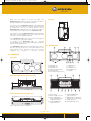
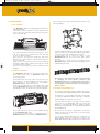
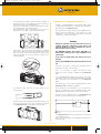
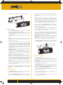
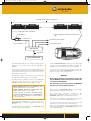
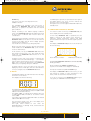
Moduled_150_manual_UK.qxd
ENGLISH
7/04/08
10:58
Page 1
MODULED 150 - MANUAL UK1
p
j
g
g
g
g
User’s manual
w w w. a y r t o n . e u
Moduled_150_manual_UK.qxd
7/04/08
10:58
Page 2
SUMMARY
01. INTRODUCTION . . . . . . . . . . . . . . . . . . . . . . . . . . . . . . . . 3
01. SERIAL NUMBER
02. SAFETY INSTRUCTIONS . . . . . . . . . . . . . . . . . . . . . . . . . 3
02. SOFTWARE VERSION
.............................
...........................
03. TEMPERATURE . . . . . . . . . . . . . . . . . . . . . . . . . . . . . . .
04. SCHEDULE COUNTER . . . . . . . . . . . . . . . . . . . . . . . . . .
05. LEDS COLOURS PRE-SET . . . . . . . . . . . . . . . . . . . . . . . .
03. USE AND APPLICATIONS . . . . . . . . . . . . . . . . . . . . . . . . 4
04. DIMENSIONS . . . . . . . . . . . . . . . . . . . . . . . . . . . . . . . . . . 5
05. DESCRIPTION . . . . . . . . . . . . . . . . . . . . . . . . . . . . . . . . . . 5
10. SETTING THE MODULED 150 VIA COUGAR 2 . . . . . . 17
06. INSTALLATION . . . . . . . . . . . . . . . . . . . . . . . . . . . . . . . . . 6
01. YOKE ASSEMBLY . . . . . . . . . . . . . . . . . . . . . . . . . . . . . . . 6
02. FLANK SIDES ASSEMBLY . . . . . . . . . . . . . . . . . . . . . . . . . 6
03. OPTIONAL FILTER HOLDER SETUP . . . . . . . . . . . . . . . . . . . 6
04. INTERNAL FILTER HOLDER SETUP . . . . . . . . . . . . . . . . . . 7
05. PROJECTOR RIGGING . . . . . . . . . . . . . . . . . . . . . . . . . . . . 8
06. PROJECTOR CONNECTION . . . . . . . . . . . . . . . . . . . . . . . . 8
07. DMX 512 CONNECTIONS . . . . . . . . . . . . . . . . . . . . . . . . . 10
11.TECHNICAL SPECIFICATIONS . . . . . . . . . . . . . . . . . . . 17
07. PROTOCOL . . . . . . . . . . . . . . . . . . . . . . . . . . . . . . . . . . . .
01. MODULED 150 RGB DMX PROTOCOL . . . . . . . . . . . . . . .
02. MODULED 150 AWW DMX PROTOCOL . . . . . . . . . . . . . . .
03. MODULED 150 AWB DMX PROTOCOL . . . . . . . . . . . . . . .
11
11
11
12
08. CONTROL . . . . . . . . . . . . . . . . . . . . . . . . . . . . . . . . . . . . .
01. INFRA-RED KEYS . . . . . . . . . . . . . . . . . . . . . . . . . . . . . .
02. DISPLAY . . . . . . . . . . . . . . . . . . . . . . . . . . . . . . . . . . . .
03. STAND BY MODE : MODULED 150 UNLOCKING . . . . . . .
12
12
13
13
09. MODULED 150 MENU . . . . . . . . . . . . . . . . . . . . . . . . . .
01. MODULED 150 MENU CHART . . . . . . . . . . . . . . . . . . . . .
02. DMX ADRESS MENU . . . . . . . . . . . . . . . . . . . . . . . . . . .
03. DMX MODE MENU . . . . . . . . . . . . . . . . . . . . . . . . . . . . .
04. OPTIONS MENU . . . . . . . . . . . . . . . . . . . . . . . . . . . . . . .
01. DIMMER . . . . . . . . . . . . . . . . . . . . . . . . . . . . . . . . . . .
02. DEFAULT VALUES . . . . . . . . . . . . . . . . . . . . . . . . . . . . .
03. BRIGHTNESS . . . . . . . . . . . . . . . . . . . . . . . . . . . . . . . .
14
14
14
14
15
15
15
15
01. OPTICS . . . . . . . . . . . . . . . . . . . . . . . . . . . . . . . . . . . . . . . . . . . . . . 17
02. SOURCE . . . . . . . . . . . . . . . . . . . . . . . . . . . . . . . . . . . . . . . . . . . . . . 17
03. COLOURS . . . . . . . . . . . . . . . . . . . . . . . . . . . . . . . . . . . . . . . . . . . . 17
04. FROST, DIFFUSION . . . . . . . . . . . . . . . . . . . . . . . . . . . . . . . . . . . . 17
05. DIMMER, STROBE . . . . . . . . . . . . . . . . . . . . . . . . . . . . . . . . . . . . . 17
06. SOFTWARE FACILITIES . . . . . . . . . . . . . . . . . . . . . . . . . . . . . . . . 17
07. CONTROL . . . . . . . . . . . . . . . . . . . . . . . . . . . . . . . . . . . . . . . . . . . . 17
08. POWER SUPPLY . . . . . . . . . . . . . . . . . . . . . . . . . . . . . . . . . . . . . . . 18
09. COOLING . . . . . . . . . . . . . . . . . . . . . . . . . . . . . . . . . . . . . . . . . . . . . 18
10. CONSTRUCTION . . . . . . . . . . . . . . . . . . . . . . . . . . . . . . . . . . . . . . 18
11. INSTALLATION . . . . . . . . . . . . . . . . . . . . . . . . . . . . . . . . . . . . . . . . 18
12. UTILIZATION SETTINGS . . . . . . . . . . . . . . . . . . . . . . . . . . . . . . . . 18
13. CONFORMITY . . . . . . . . . . . . . . . . . . . . . . . . . . . . . . . . . . . . . . . . . 18
14. WEIGHT . . . . . . . . . . . . . . . . . . . . . . . . . . . . . . . . . . . . . . . . . . . . . . 18
15. PRODUCTS CODES . . . . . . . . . . . . . . . . . . . . . . . . . . . . . . . . . . . . 18
16. ACCESSORIES . . . . . . . . . . . . . . . . . . . . . . . . . . . . . . . . . . . . . . . . 18
12. MAINTENANCE . . . . . . . . . . . . . . . . . . . . . . . . . . . . . . . 18
01. CLEANING . . . . . . . . . . . . . . . . . . . . . . . . . . . . . . . . . . . 18
02. SUPERVISION . . . . . . . . . . . . . . . . . . . . . . . . . . . . . . . . 18
13. SOFTWARE UPDATE . . . . . . . . . . . . . . . . . . . . . . . . . . . 18
14. WARRANTY . . . . . . . . . . . . . . . . . . . . . . . . . . . . . . . . . . . 19
05. INFORMATION MENU . . . . . . . . . . . . . . . . . . . . . . . . . . . . . . . . . 16
SUMMARY
2
16
16
16
16
17
www.ayrton.eu
Reproduction of this document, entirely or in part, is strictly prohibited unless otherwised authorized. All rights reserved.
Moduled_150_manual_UK.qxd
7/04/08
10:58
Page 3
01. INTRODUCTION
02. SAFETY INSTRUCTIONS
Thank you for choosing AYRTON’s products and for your trust
in MODULED 150.
Before installing and using your MODULED 150, carefully
read the instructions and safety precautions of use listed
below.
Your MODULED 150 needs other AYRTON accessories
for use. These accessories, not supplied with your
MODULED 150, are :
WARNING!
RISK OF ELECTRIC SHOCK
Be careful when handling, this device
requires a high voltage which may cause
a risk of electric shock.
› Connection box EASYBOX HD
› AYRTON Multifunction hybrid connection cables (these
cables merge power and command DMX signals)
› Other accessories needed according to application
requirements (Filter holders and diffusion filters,…)
Your MODULED 150 left our factory in perfect working order.
However, if you notice a defect, you should immediately
contact your AYRTON dealer before use.
WARNING !
This product is not suitable for home use.
You are in possession of a professional product with
many applications. Before installation, make sure your
MODULED 150 has not suffered damage during transport. If
it is damaged in anyway, do not use this product and contact
your AYRTON dealer immediately.
If you would like additional information, or to get the latest
software update for your MODULED 150, please visit our
website www.ayrton.eu.
The manufacturer cannot be held liable for damages caused
by failure to follow safety instructions, installation or
assembly, mentioned in this manual, or any change in your
MODULED 150.
Failure to comply with the safety instructions, installation or
assembly and editing your MODULED 150 lead to the
nullification of the warranty.
Check that the Mains voltage does not exceed the maximum
allowable voltage.
Make sure your electric installation is up to standard rules.
For your own safety and that of others, please read this
manual before the first operation of this device.
Any person involved in the installation, use or maintenance of
your MODULED 150 must:
For reliable and safe operation, your MODULED 150 requires
the use of a power cable hybrid type, specifically designed
and marketed by AYRTON. This cable, not included with the
product, is available as an option in a wide variety of lengths.
You should use only the power cables original designed and
manufactured by AYRTON with your MODULED 150.
› Be qualified for this type of operation
› Strictly respect the instructions mentioned in this manual
Please take the time to fully and carefully read the manual
before installing and using your MODULED 150, in order to
gain a thorough knowledge of the conditions of use, safety
instructions and all information concerning this product.
Once you have become familiar with the Moduled 150, we
recommend you keep a copy of these instructions for
reference.
Always check the cables for physical damage such as gashes,
splices or breakages.
Handle these power cables with extreme caution if they are
connected to the mains.
Always remember to check your MODULED 150 and the
power cables you use together before each use.
All information contained in this manual are subject to change
without notice.
Your MODULED 150 complies with the safety standards of
Class 1.
Earth to the unit is supplied through the multifunction cable
and EASYBOX HD, The EASYBOX HD must always be
connected to earth.
AYRTON reserves the right to change and improve all the
products in its range over time, without having to incorporate
the changes in the products previously sold.
The installation and electrical connections must be performed
by a certified installer. AYRTON declines liability for any
installation of your MODULED 150 by an unqualified person.
01. INTRODUCTION
Reproduction of this document, entirely or in part, is strictly prohibited unless otherwised authorized. All rights reserved.
www.ayrton.eu
3
Moduled_150_manual_UK.qxd
7/04/08
10:58
Page 4
WARNING !
Never move your MODULED 150 by the power cable. Use
the handle of the fixture’s body.
Never connect or disconnect the power hybrid cable
from your MODULED 150 when power is connected.
This may damage the internal electronics
of your MODULED 150 and require repair.
Always cut power to your MODULED 150 by removing
the power of connection box EASYBOX
HD before connection or disconnection
of your MODULED 150.
To disconnect your MODULED 150, do not pull on the power
cable! Unscrew the blue ring connector of the power cable
(not supplied) until its full disengagement, and then gently pull
the connector to unplug the cable.
Do not connect or disconnect the power cable from your
MODULED 150 with wet hands.
Be careful to never leave objects or liquid inside your
MODULED 150 during operations set up filters dissemination
within the device.
On first use, smells may come from your MODULED 150. It
is a normal phenomenon that will fade after a few minutes of
use.
03. USE AND APPLICATIONS
Your MODULED 150 is a fixture with multiple LED light
sources (Light Emitting Diode) for professional use (Show
Events, Clubs, Architectural lighting, Exhibitions, Museums,
TV stages, Theatres…).
It was designed to be used indoors or outdoors.
Its index of protection is IP66.
Your MODULED 150 may in no case be partly or fully
submerged, even temporarily.
Condensation may form on your MODULED 150 in the
following cases:
› Immediately after having lit the device.
› In a steamed or very wet room or environment.
› When the MODULED 150 is brought from a cold
environment in a warm environment.
In these cases, you must wait for the fixture to be returned to
the ambient temperature of the room where it is placed
before use.
If you open your MODULED 150 (for an introduction of a
diffusion filter, for example), moisture from the air trapped in
the device can cause the formation of condensation inside
the fixture the next time it is used. This condensation will
quickly fade as the MODULED 150 has an exhaust system
humidity and pressure compensation valve fitted.
Do not shake your MODULED 150 at its setup or its
manipulation.
The choice of installation/location of your MODULED 150 is
very important:
› You must not expose it to a heat source.
› You should not install it near flammable materials.
› You must ensure that dust and debris will not form on the
housing and remain in the cooling fins of the body of
MODULED 150, which may alter its optimal cooling and
impair its operation.
› The MODULED 150 must be installed away from the public
and all persons who are not empowered to maintain on the
fixture.
You must comply with a minimum distance of 0.5 m between
the surface output of the light beam and object to be
illuminated.
By the nature of its principle of cooling (natural convection),
you should never impede free air to circulate around the body
of the fixture. You must provide a minimum clearance of 0.5
m around your MODULED 150 to promote cooling.
The installation of a MODULED 150 in a pit of soil or other
confined enclosure can be done only under certain conditions.
The MODULED 150 ensures its natural convection cooling, it
is appropriate in this case installation to establish a forced
ventilation system suitable for the air to circulate around the
device.
The air must be constantly renewed, it can not be operated in
a closed circuit. Failure to comply with these constraints
could result in the destruction or premature wear out of
MODULED 150, in which AYRTON could not be held
responsible. Please consult your AYRTON dealer for more
information on this type of facility.
No load can be applied on MODULED 150. It should never
been installed into a recess. where objects may be placed on
it or allow the passage of a person or vehicle or other object
on the MODULED 150.
Never project or drop your MODULED 150 upon hard
surfaces and all objects made of glass or porcelain (bottles,
crockery, marbles,…). The MODULED 150 consists of
aluminium smelting and glass, which makes it highly resistant
but not unbreakable.
Falling objects made of hard materials such as steel or glass
on the device may cause breakage of the glass or body
thereof. AYRTON can not be held responsible for the
breakage of the glass or the body of the fixture, which is
excluded from the guarantee.
Warning: The temperature of the glass surface of your
MODULED 150 is likely to reach 45°C, depending on its use.
The body temperature of the aluminium device is however
expected to reach 70°C. Verify that the application you
intended to install your MODULED 150 is compatible with
these informations.
03. USE AND APPLICATIONS
4
www.ayrton.eu
Reproduction of this document, entirely or in part, is strictly prohibited unless otherwised authorized. All rights reserved.
Moduled_150_manual_UK.qxd
7/04/08
10:58
Page 5
Make sure the support on which you hang your
MODULED 150 can safely accept the weight of this device,
6.4 Kg, including all the safety factors required.
SIDE VIEW :
91.5
59.8
27
You must secure your MODULED 150 grip to the load-bearing
structure with a safety bond or strap. The safety bond must
be attached to the ring of security present on the
MODULED 150, dedicated to that use. This ring of security is
not provided for the suspension of your MODULED 150.
You should not use your MODULED 150 before being familiar
with these recommendations, and you should not allow
intervention on it by unqualified persons.
If your MODULED 150 should not be used for a long period,
you must disconnect the power supply.
To transport your MODULED 150, it is strongly
recommended to use its full original packaging, including 2
thermoformed shell protection.
141.7
150
Ø35
61
95.7
05 – DESCRIPTION
Your MODULED 150 should not be discarded in the trash, it
must be recycled, as the logo on the label affixed to the
fixture. Please refer to the laws in force in your country
regarding
the
recycling
of
electronic
devices.
1
2
11
3
4
04 - DIMENSIONS
FRONT VIEW:
207.5
150
181.4
6
476
7
18
20
10
9
5
7. « MODE » Key
8. « UP » Key
9. « DOWN » Key
10. « ENTER » Key
11. Display
1. LED Matrix n°1
2. LED Matrix n°2
3. LED Matrix n°3
4. Tempered glass window
5. Aluminium front
6. Front window fixing screws
VIEW FROM ABOVE (WITHOUT THE FLANKS SIDE):
8
19
18
20
267.8
207.5
150
238
75
3 HOLESØ10.5
18
15
12
14
13
16
17
18
VIEW FROM ABOVE (WITH THE FLANKS SIDE):
468
16
92
76.5
2 HOLES M10
12. Fixture body
13. Power supply unit cover
14. Fixture Identification
sticker bearing the serial
number and model
15. 7-Core-HD-Multifonction
input Connector
17. 7-Core-HD-Multifonction
output Connector
18. Tapped holes for fastening
flanges Sides or safety ring
19. Suspension yoke
20. Yoke tightening wheel
note : all dimension are in millimeters.
04 - DIMENSIONS
Reproduction of this document, entirely or in part, is strictly prohibited unless otherwised authorized. All rights reserved.
www.ayrton.eu
5
Moduled_150_manual_UK.qxd
7/04/08
10:58
Page 6
06. INSTALLATION
The assembly of the 2 sides made within the timeline of the
following diagram :
01. YOKE ASSEMBLY
Your MODULED 150 comes partially disassembled in its
original packaging.
If you want to use the suspension yoke provided with the
device, you need to mount the various elements as shown
on the following chart :
First the 4 pillars should be screwed (16mm) to the flanks,
then screw the 8 screws TFHC M5 x 10mm (4 per side) to
ensure the flanks have solidarity between them.
It will remain only to screw the sides on each
MODULED 150 with the screws CHC M5 x 22mm
provided.
This produces a linear projector including several
MODULED 150, as shown in the following diagram where
3 MODULED are linked :
You must first install on the body of the fixture, on either
side of the PSU cover, 2 brackets with the CHC M5
screws 2 x 16mm provided.
Next, place the yoke between media lyre and insert
between these parts washers notched 27mm diameter
(one on each side).
Finally, screw on each side of the yoke wheel clamping
head M8 x 20mm plastic, passing it through the media
yoke and the puck serrated.
Check the correct setting of the various elements of this
package.
02. FLANK SIDES ASSEMBLY
The MODULED 150 also comes with 2 lateral sides,
which allow other types of MODULED 150 to be
connected together.
These flanks allow to fix the fixture from the rear on an
adjusted baking, using the M10 fixing inserts located in
these flanks, for the realization of “CLUSTERS”
MODULED 150 to a chassis for example .
In this case, the sides are to be mounted directly onto the
body of MODULED 150, using the 4 x 22mm screw M5
provided (2 per side), as shown in the following diagram :
This system is only designed to offer a convenient way
of matching the pixel distance between each
MODULED 150 to offer excellent matrix characteristics
it must not be moved or carried thus formed, to do so
risks breakage of various elements on this assembly or
fixture colapse.
03. OPTIONAL FILTER HOLDER SETUP :
An optional external filter holder is available as an option
for your MODULED 150 (AYRTON product code: 025392).
This allows you to insert a filter especially for beam angle
increasing of MODULED 150. A wide range of diffusion
filters is available as an option for such use.
The filter holder also allows mounting of various optional
accessories on your MODULED 150, such as Cap (Full
Barndoor), Semi-cap (Half Barndoor), Matrix horizontal
masking (Horizontal Barndoor) or Vertical masking Matrix
(Vertical Barndoor).
These sides can also be used to ensure solidarity among
several MODULED 150 online.
In this case the flanks must be solidified between 2
MODULED 150 before assembling on MODULED 150.
All references and specific characteristics of all these
optional accessories can be found in the Accessories
section of this manual.
The optional external holder filter kit is composed of 3
parts, 2 plastic clips to be installed on the front of the
MODULED 150, and holder filter allowing to drop the filter
06. INSTALLATION
6
www.ayrton.eu
Reproduction of this document, entirely or in part, is strictly prohibited unless otherwised authorized. All rights reserved.
Moduled_150_manual_UK.qxd
7/04/08
10:58
Page 7
in and maintain the diffusion filter (this filter, available in
different versions, is not supplied in the kit external filter
holder and must be ordered separately).
The various components of this kit external filter holders
are represented on the following basis :
(The MODULED 150 is represented here only for
illustration, it is not part of Kit external filter holder)
04. MOUNTING THE FILTER WITHIN THE MODULED 150
As part of a fixed installation, it is possible under certain
conditions described below to install an optional diffusion
filter directly in the MODULED 150.
This requires the opening of the unit, the establishment of
a filter previously designed for this specific use, and
replacement of the front panel respecting the special
constraints of compression gasket.
WARNING:
During that operation, you will have direct access to
sensitive electronic components of the device, and
improper handling can cause a malfunction or even a
defect in fixture water resistance.
Caring in the Side 2 clips set up, according to the drawing
above. The 2 clips side of this kit can be fastened on either
side of the device and are held in place by locking in the
wings at the back of the fixture body, as shown in the
following diagram :
The AYRTON guarantee will not be applicable if a
malfunction or leakage occurs after installation of an
interior filter.
If you have any doubt about this feature, don’t do it
yourself!
Contact your AYRTON dealer, they will be able to do it for
you.
However, if you want to continue this operation, here in
detail the procedure to be followed.
First, it is necessary to adjust the diffusion filter
dimensions to be correctly installed in the MODULED
150.
Use only AYRTON filters inside the fixture, the use of any
other type of filter non marketed by AYRTON is excluded
and could result in the deterioration of your MODULED
150.
The dimensions of the special AYRTON diffusion filter
MODULED 150 are 440 mm x 100 mm.
The diffusion filter slips into the filter holder in the
following way:
These dimensions are provided for use of this filter kit
with the external filter holder (AYRTON product code:
025392) detailed in a previous section of this manual.
This filter to be installed directly in the MODULED 150,
shall be cut in the following sizes (in millimeters) :
430
64 ±1
99 ±1
99
41 ±1
Once the filter holder equipped with its diffusion filter, you
can now drag into one of the grooves clips, the mounted
kit of MODULED 150 corresponds to the following :
10 at 45˚
The MODULED 150 may now be opened for the insertion
of the diffusion filter.
A few tools are needed, as a 3mm BTR key and a game of
thickness hold.
06. INSTALLATION
Reproduction of this document, entirely or in part, is strictly prohibited unless otherwised authorized. All rights reserved.
www.ayrton.eu
7
Moduled_150_manual_UK.qxd
7/04/08
10:58
Page 8
licensed and able to withstand a load 10 times greater
than the weight of the projector for 1 hour and without any
distortion.
The operation is illustrated on the following chart :
Attach the necklace suspension on the central hole of the
fixture’s yoke with a M10 screw and a nut (these
elements make screws should be a minimum 8.8 grade).
Use washers M10 between the different elements, and
make sure the fixing once tightened will not go loose. The
use of star washers or Nyloc Nut is recommended.
Before hanging your MODULED 150 to the structure,
make sure that the associated accessories (filter holder,
for example) are properly set.
Hang your MODULED 150 on the structure by placing the
front of the base to the area to be illuminated. Make sure
you are locking collars suspension.
Operation details :
› Put your MODULED 150 on a work surface adapted and
free from dirt, dust and various liquids.
› With a BTR 3mm key, loosen the 4 front fixture screws, and
then conclude with the 4 screws located at the corner of
the front panel.
› Gently remove the front, and then remove the silicone seal
also.
You must install an independent safety sling to
supplement the failure of the main suspension. This sling
security shall be capable of withstanding a load 10 times
greater than the weight of the projector.
The safety bond must be set at the ring of security
MODULED 150. This ring of security, supplied with the
unit should be screwed into the body of the fixture as
described in the Description section of this manual.
Warning, from that moment, you have access to the
electronic system of the MODULED 150, work with
concentration and care.
› Put down the fixture front cover upon your work area taking
care not to place the moduled on any objects that may
damage the device, screen down and seal housing upwards.
› Set up the diffusion filter (previously cut) in the space
available inside the front, caring to place the portion of the
filter holes dedicated to infrared keys of the fixture in front
of those holes.
› Place the joint in the slot provided on the front panel of
MODULED 150.
› Gently remove the body of MODULED 150, keeping special
attention to correctly placing the seal on the entire periphery
of the device.
› Keep your hands between the front and the body of the
fixture, then return it, front upwards.
Replace the 8 screws on the front panel in place by
screwing on a few turns only, leave the screws loose.
› Tighten the 4 first central screws, in order to leave a gap
of 2 mm between the front and the body of the fixture, and
make sure the gasket stays in place during this phase.
› Repeat this process for the 4 corner screws of the front
panel.
› With a the game shims installed, tighten the screws one
by one, leaving a distance between the front and the body
of the device of 1.5 mm.
The following diagram illustrates the correctness hanging
of a MODULED 150 on a support-type tubular structure
06. MODULED 150 CONNECTION
The operation is now over, it remains to verify the correct
operating of your MODULED 150 before it is permanently
installed.
05. PROJECTOR RIGGING
Your MODULED 150 can not work alone.
Its use requires the use of a connection box EASYBOX HD
(AYRTON Code: 075130) and specific AYRTON cables of
various length.
The use of an external controller issuing a command signal
format DMX512 is also required.
The MODULED 150 can be connected in series with each
other through the use of specific AYRTON cables, the exit
of previous MODULED 150 being connected to the
entrance to the following MODULED 150.
The power supply for the fixtures passes through the box
connection EASYBOX HD.
Your MODULED 150 can mounted on a structure in any
position without affecting its operation.
The command signal DMX 512 also passes by the
connection box EASYBOX HD.
To install your MODULED 150, you must use suspension
collars with thread M10 (not supplied). They must be
The following diagram illustrates the connection of a
series of MODULED 150 :
06. INSTALLATION
8
www.ayrton.eu
Reproduction of this document, entirely or in part, is strictly prohibited unless otherwised authorized. All rights reserved.
Moduled_150_manual_UK.qxd
7/04/08
10:58
Page 9
MAX. MODULED 150 QUANTITY : SEE MANUAL
CABLE MAX. LENGTH : SEE MANUAL
EASYBOX HD
120
DMX TERMINATOR CONNECTOR FOR MODULED 150
MAIN SUPPLY
TO OTHER MODULED 150 CHAINS
TO OTHER DMX FIXTURES
XLR 3 PIN DMX CABLE
DMX SPLITER
DMX SIGNAL
DMX LIGHTING DESK
THE MODULED 150 has an internal universal power
supply, so
so ititcan
canwork
workin in
either
either
110110
AC,VAC,
AC 208V
208 or
VAC
230V
or
AC. VAC.
230
On the last MODULED 150 of the line, it is recommended
to place a specific AYRTON cap DMX line ending. The
AYRTON code of this optional accessory is: 025398.
However, the currents vary for each mains voltage level. It
is necessary to adjust the amount of MODULED 150 that
can be connected in series in a row in terms of the sector
and lengths of cable used.
If you
IF
you do
do not
not use
use this
this accessory,
accessory, be
be sure to set up on the
output connector of the last MODULED 150 of the line the
cap seal of origin, came with the device.
WARNING:
The Maximum current consumption of the line composed
of MODULED 150 should never exceed 10A.
The table below will indicate the amount of MODULED
150 which can be connected on a single connection box
EASYBOX HD depending on the conditions of use :
Never perform connection or disconnection of any cable
from the MODULED 150 line without power off before the
connection box EASYBOX HD.
This Golden
The
Golden Rule
Rule is
is particularly important for MODULED
150, unless you risk to damage the products.
Voltage 230V
230 VAC:
AC: Maximum 10 MODULED 150
Connected in series in a sector line.
Voltage 110
110 VVAC:
AC: Maximum
Maximum 55 MODULED
MODULED 150
Connected in series in a sector line.
In any case, do not exceed a 50 meters length
between EASYBOX HD and the last MODULED
150 of the line, consisting in several devices
connected in series.
The connection of 2 MODULED 150 side by side needs a
hybrid multifunction 0.28 m cable length.
The multifunction connectors installed on the
multipurpose AYRTON cables for connecting the
MODULED 150 are elements watertight locking.
Their correct use requires an understanding of the method
of connection or disconnection appropriate to use.
Connecting the EASYBOX HD, and therefore your
MODULED 150, on a dimmer highly deteriorates these
devices!
The EASYBOX HD (and therefore your MODULED 150)
must be connected to the Earth.
You must not turn the body connectors, but act on the
locking ring for their connection or disconnection.
Failure to comply with this rule can cause damage to the
cables and risk breaking your MODULED 150 when used
with a damaged
cable.
cable.
06. INSTALLATION
Reproduction of this document, entirely or in part, is strictly prohibited unless otherwised authorized. All rights reserved.
www.ayrton.eu
9
Moduled_150_manual_UK.qxd
7/04/08
10:58
Page 10
To put power up your MODULED 150, it must first have
been connected as described above. Then turn to the right
description of the PowerCON EASYBOX HD enclosure to
feed your MODULED 150.
The charts below show you how :
Connect
To cut off power to your MODULED 150, you pull the tab
to unlock position in the PowerCON, then turn this
portfolio to the left, then finally remove this portfolio
Enclosure this connection EAXYBOX HD. Your MODULED
is now powered off.
1
2
07. DMX 512 CONNECTIONS
The cables used for routing the DMX512 signal command
until EASYBOX HD connection box that powers your
MODULED 150 must conform to the standards EIA 422A
& EIA 485. Make sure to use the shielded cable to twisted
pair. Never use a microphone cable, it does not permit
reliable transmission over long distances. For lengths in
excess of 300 meters, it is advisable to use an amplifier
line.
Disconnect
1
Connect the cable from your DMX controller on the
EASYBOX HD base DMX IN connection that feeds your
MODULED 150.
2
The base DMX IN Enclosure of the EASYBOX HD is the
3-pin XLR.
The pin wiring is as follows:
1. DMX GND
2. DATA (-)
3. DATA (+)
The connection box EASYBOX HD has no DMX exit, as
the DMX 512 standard prohibits the DMX signal 512
wiring in star, only the wiring in series of different DMX
receptors (including MODULED 150).
If you need to use more than one line consisting of one or
more MODULED 150, or other devices controlled by DMX
with your DMX controller, it is necessary to use a DMX
Splitter allowing you from a line of DMX512 to obtain
several DMX512 lines identical but separate.
The connection box EASYBOX HD comes without power
cable.
A detailed lockable and removable type PowerCON
(Model filed NEUTRIK) is provided with the EASYBOX HD,
for the purpose of adapting a power cord with a Male plug
corresponding to the standard of your country.
Depending on the country, the identification of cables
sector is different.
You are reminded below, in order to achieve a cable line.
Connections
Wire
Contact
Brown
Phase
Blue
Neutre
Yellow/Green
Earth
Marks
International
UK
L
Red
N
black
EARTH
Green
The use of this device offers the advantage of protecting
the different lines DMX obtained by an electrically
insulating, sharply limiting the damage that can occur in
the event of damage to one of the devices in the DMX
channel.
This type of device is offered by a wide variety of
specialized manufacturers in DMX signal 512 management.
To ensure reliable transmission of DMX information, it is
imperative to complete the DMX 512 line with a DMX
terminating cap specific to AYRTON. This is to be put in
place on the last MODULED 150 of the line.
The Code AYRTON this optional accessory is: 025398.
If you do not use this accessory, be sure to set up on the
output connector of the last MODULED 150 of the line,
cap seal of origin, came with the device.
06. INSTALLATION
10
www.ayrton.eu
Reproduction of this document, entirely or in part, is strictly prohibited unless otherwised authorized. All rights reserved.
Moduled_150_manual_UK.qxd
7/04/08
10:58
Page 11
07. PROTOCOL
The MODULED 150 is available in several versions of LED
light sources.
5.
6.
7.
8.
9.
GREEN
BLUE
RED
GREEN
BLUE
(For
(For
(For
(For
(For
18
18
18
18
18
LEDS
LEDS
LEDS
LEDS
LEDS
Matrix
Matrix
Matrix
Matrix
Matrix
n°2)
n°2)
n°3)
n°3)
n°3)
The different versions offered are:
› MODULED 150 RGB
This projector combines LED sources such as RED, GREEN
and BLUE, which provides a palette of 16.7 million colours,
colours additive.
› MODULED 150 AWW
This projector combines LED sources of WHITE and AMBER,
which provides a white light color temperature varies.
› AWB MODULED 150
This projector combines LED sources such as WHITE, BLUE
and AMBER, which provides a white light variable color
temperature larger than the model version AWW.
Depending on the type of MODULED 150 used, the DMX of
these devices is different, the number of channels required
for DMX control varies.
In addition, these modes have several DMX settings, which
provide extensive opportunities, you can actually adjust the
number of channels DMX necessary for the operation of the
fixture.
A flexible control by the user according to its specific needs is
then proposed.
› MODE 10 channels DMX (10cH)
1. RED
(For 18 LEDS Matrix n°1)
2. GREEN
(For 18 LEDS Matrix n°1)
3. BLUE
(For 18 LEDS Matrix n°1)
4. RED
(For 18 LEDS Matrix n°2)
5. GREEN
(For 18 LEDS Matrix n°2)
6. BLUE
(For 18 LEDS Matrix n°2)
7. RED
(For 18 LEDS Matrix n°3)
8. GREEN
(For 18LEDS Matrix n°3)
9. BLUE
(For 18LEDS Matrix n°3)
10. DIMMER (0 : dimmer closed > 255 : dimmer opened)
› MODE 12 channels DMX (12cH)
1. RED
(For 18LEDS Matrix n°1)
2. GREEN
(For 18LEDS Matrix n°1)
3. BLUE
(For 18LEDS Matrix n°1)
4. RED
(For 18LEDS Matrix n°2)
5. GREEN
(For 18LEDS Matrix n°2)
6. BLUE
(For 18LEDS Matrix n°2)
7. RED
(For 18LEDS Matrix n°3)
8. GREEN
(For 18LEDS Matrix n°3)
9. BLUE
(For 18LEDS Matrix n°3)
10. STROBE (0 : no strobe > to 255 :
extensive strobe effect)
11. COLOR 0 : Slow colour variation > 255 :
MACRO fast colour variation)
12. DIMMER (0 : dimmer closed > 255 : dimmer opened)
01. MODULED 150 RGB DMX PROTOCOL
The MODULED 150 RGB can be configured in different
6 DMX MODES.
The DMX mode that suits best the user is selected via the
MODE menu of the fixture.
› MODE 3 channels DMX (03cH)
1. RED
(For all 18 LEDS Matrix)
2. GREEN
(For all 18 LEDS Matrix)
3. BLUE
(For all 18 LEDS Matrix)
› MODE 3 channels DMX (03cH)
1. AMBER
(For all 18 LEDS Matrix)
2. WHITE
(For all 18 LEDS Matrix)
3. DIMMER (0 : dimmer closed > 255 : dimmer opened)
› MODE 6 channels DMX (06cH)
1. RED
(For all 18 LEDS Matrix)
2. GREEN
(For all 18 LEDS Matrix)
3. BLUE
(For all 18 LEDS Matrix)
4. STROBE (0 : no strobe > to 255 :
extensive strobe effect)
5. COLOR
(0 : Slow colour variation > 255 :
MACRO fast colour variation)
6. DIMMER (0 : dimmer closed > 255 : dimmer opened)
n°1)
n°1)
n°1)
n°2)
The MODULED 150 RGB can be configured in different
6 DMX MODES.
The DMX mode that suits best the user is selected via the
MODE menu of the fixture.
› MODE 2 channels DMX (02cH)
1. AMBER
(For all 18 LEDS Matrix)
2. WHITE
(For all 18 LEDS Matrix)
› MODE 4 channels DMX (04cH)
1. RED
(For all 18 LEDS Matrix)
2. GREEN
(For all 18 LEDS Matrix)
3. BLUE
(For all 18 LEDS Matrix)
4. DIMMER (0 : dimmer closed => 255 :
dimmer opened)
› MODE 9 channels DMX (09cH)
1. RED
(For 18 LEDS Matrix
2. GREEN
(For 18 LEDS Matrix
3. BLUE
(For 18 LEDS Matrix
4. RED
(For 18 LEDS Matrix
02. MODULED 150 AWW DMX PROTOCOL
› MODE 5 channels DMX (05cH)
1. AMBER
(For all 18 LEDS Matrix)
2. WHITE
(For all 18 LEDS Matrix)
3. STROBE (0 : no strobe > to 255 : fast strobe effect)
4. COLOR
(0 : AMBER > 128 : AMBER + WHITE
TEMP.
> 255 : WHITE)
5. DIMMER (0 : dimmer closed > 255 : dimmer opened)
› MODE 6 channels DMX (06cH)
1. AMBER
(For 18LEDS Matrix n°1)
2. WHITE
(For 18LEDS Matrix n°1)
3. AMBER
(For 18LEDS Matrix n°2)
4. WHITE
(For 18LEDS Matrix n°2)
5. AMBER
(For 18LEDS Matrix n°3)
6. WHITE
(For 18LEDS Matrix n°3)
07. PROTOCOL :
Reproduction of this document, entirely or in part, is strictly prohibited unless otherwised authorized. All rights reserved.
www.ayrton.eu
11
Moduled_150_manual_UK.qxd
7/04/08
10:58
Page 12
3. BLUE
4. AMBER
5. WHITE
6. BLUE
7. AMBER
8. WHITE
9. BLUE
10. DIMMER
› MODE 7 channels DMX (07cH)
1. AMBER
(For 18LEDS Matrix n°1)
2. WHITE
(For 18LEDS Matrix n°1)
3. AMBER
(For 18LEDS Matrix n°2)
4. WHITE
(For 18LEDS Matrix n°2)
5. AMBER
(For 18LEDS Matrix n°3)
6. WHITE
(For 18LEDS Matrix n°3)
7. DIMMER (0 : dimmer closed => 255 : dimmer opened)
› MODE 9 channels DMX (09cH)
1. AMBER
(For 18LEDS Matrix n°1)
2. WHITE
(For 18LEDS Matrix n°1)
3. AMBER
(For 18LEDS Matrix n°2)
4. WHITE
(For 18LEDS Matrix n°2)
5. AMBER
(For 18LEDS Matrix n°3)
6. WHITE
(For 18LEDS Matrix n°3)
7. STROBE (0 : no strobe > to 255 :
TEMP.
fast strobe effect)
8. COLOR
(0 : AMBER > 128 : AMBER + WHITE
> 255 : WHITE)
9. DIMMER (0 : dimmer closed > 255 : dimmer opened)
(For 18 LEDS Matrix n°1)
(For 18 LEDS Matrix n°2)
(For 18 LEDS Matrix n°2)
(For 18 LEDS Matrix n°2)
(For 18 LEDS Matrix n°3)
(For 18 LEDS Matrix n°3)
(For 18 LEDS Matrix n°3)
(0 : dimmer closed => 255 : dimmer opened)
› MODE 12 channels DMX (12cH)
1. AMBER
(For 18 LEDS Matrix n°1)
2. WHITE
(For 18 LEDS Matrix n°1)
3. BLUE
(For 18 LEDS Matrix n°1)
4. AMBER
(For 18 LEDS Matrix n°2)
5. WHITE
(For 18 LEDS Matrix n°2)
6. BLUE
(For 18 LEDS Matrix n°2)
7. AMBER
(For 18 LEDS Matrix n°3)
8. WHITE
(For 18 LEDS Matrix n°3)
9. BLUE
(For 18 LEDS Matrix n°3)
10. STROBE 0 : no strobe > to 255 : fast strobe effect )
11. COLOR (0 : AMBER > 64 : AMBER + WHITE
TEMP.
> 128 : WHITE >192 : WHITE + BLUE
> 255 : BLUE)
12. DIMMER (0 : dimmer closed > 255 : dimmer opened)
03. MODULED 150 AWB DMX PROTOCOL
The MODULED 150 RGB can be configured in different
6 DMX MODES.
08. CONTROL
The DMX mode that suits best the user is selected via the
MODE menu of the fixture.
› MODE 3 channels DMX (03cH)
1. AMBER
(For all 18 LEDS Matrix)
2. WHITE
(For all 18 LEDS Matrix)
3. BLUE
(For all 18 LEDS Matrix)
The MODULED 150 has an integrated user interface,
composed of a 4-digit LED display and 4 buttons located on
the fixture’s front.
These elements provide access to the drop-down menu
MODULED 150 authorizing the consultation or change its
parameters, such as:
› DMX Address
› MODE 4 channels DMX (04cH)
1. AMBER
(For all 18 LEDS Matrix)
2. WHITE
(For all 18 LEDS Matrix)
3. BLUE
(For all 18 LEDS Matrix)
4. DIMMER (0 : dimmer closed > 255 : dimmer opened)
› Modes of operation ( DMX channels figure )
› Hour Count Schedule
› Internal Temperature
› MODE 6 channels DMX (06cH)
1. AMBER
(For all 18 LEDS Matrix)
2. WHITE
(For all 18 LEDS Matrix)
3. BLUE
(For all 18 LEDS Matrix)
4. STROBE (0 : no strobe => to 255 : fast strobe effect )
5. COLOR
(0 : AMBER => 64 : AMBER + WHITE
TEMP.
> 128 : WHITE >192 : WHITE + BLUE
> 255 : BLUE)
6. DIMMER (0 : dimmer closed => 255 : dimmer opened)
› MODE 9 channels DMX (09cH)
1. AMBER
(For 18 LEDS Matrix
2. WHITE
(For 18 LEDS Matrix
3. BLUE
(For 18 LEDS Matrix
4. AMBER
(For 18 LEDS Matrix
5. WHITE
(For 18 LEDS Matrix
6. BLUE
(For 18 LEDS Matrix
7. AMBER
(For 18 LEDS Matrix
8. WHITE
(For 18 LEDS Matrix
9. BLUE
(For 18 LEDS Matrix
› Software version
› And many more…
01. INFRA-REDS KEYS
n°1)
n°1)
n°1)
n°2)
n°2)
n°2)
n°3)
n°3)
n°3)
Searching in the drop-down menu MODULED 150 is
effected by means of 4 infra- RED keys located on the
front of the fixture.
The functionality of these keys which described below.
MODE Key
Performs a step backwards in the tree of dropdown
Allows you to return to your base display
UP Key
Go to the next section of the menu
Allows a selected value increment
› MODE 10 channels DMX (10cH
1. AMBER
(For 18 LEDS Matrix n°1)
2. WHITE
(For 18 LEDS Matrix n°1)
DOWN Key
Scrolls to the previous menu item
Allows a decrement selected value
08. CONTROL
12
www.ayrton.eu
Reproduction of this document, entirely or in part, is strictly prohibited unless otherwised authorized. All rights reserved.
Moduled_150_manual_UK.qxd
7/04/08
10:58
Page 13
If a DMX signal is present, the point at the bottom right of
the display flickers once every second to indicate the
presence of the command signal.
This light is active even though the MODULED 150 is into
standby mode.
ENTER Key
Lets go into a section of the drop-down menu
Validates selection
The infra-REDs keys self-adjust every time power is
applied to the MODULED 150, and then continuously
during use, to operate in accordance with the external
light conditions.
03. STAND BY MODE : MODULED 150 UNLOCKING
Indeed, according to the ambient lighting conditions
where is the MODULED 150, infrared radiation perceived
by these keys is different and must be taken into
consideration.
During this Power On phase, which lasts a few seconds,
MODULED 150 does not take into account the orders it
receives from DMX, and the device display presents
4 points from the bottom lit.
You should not touch these keys during this phase.
If no action is taken on the keys of MODULED 150, the
device rapidly turns into Stand-by mode.
In this mode, MODULED 150 is operational, but the
display is turned off, only remain on the presence of
witnesses Voltage (permanent ignition) and DMX
presence (flashes once per second if the signal is present
DMX).
The display of MODULED 150 present in this mode look
like the following :
Please note that when using the optional external filter
holder installed on the MODULED 150, you do not have
access to infra-red keys.
In this scenario, set up your MODULED 150 without the
filter holder, and then put it off. Then install the filter
holder, put your MODULED 150 switched on. It will
function properly.
Power Presence indicator
A lighting sources with a big amount of infra-red rays
(sunlight, fluorescent tubes based light, …) can interfere
with the proper functionning of the keys of the device.
Make sure to reduce the illumination of the MODULED
150 keys by such lighting during the calibration.
A simple method is to put one hand on the top of the
display/keys area to mask light, while the other hand acts
on keys to navigate into the MODULED 150 menu.
02. DISPLAY
A 4-digit LEDS display can read information from the dropdown menu on the device.
This display looks like the following:
DMX Presence indicator
To unlock the MODULED 150 when it is in the Standby
mode, you must :
Press simultaneously MODE and ENTER keys.
(2 points in the middle of the display are illuminated)
Then press simultaneously UP and DOWN keys.
The display of MODULED 150 becomes active, you can
then change its settings or review information for the
fixture, which are stored in its internal memory.
If you do not touch its keys, MODULED 150 then goes
very quickly on STANDBY mode automatically.
The MODULED 150 default display (when it is unlocked)
corresponds to the DMX address settled on it (001 in DMX
address in the illustration above).
The display “A001” for example shows that the unit is set
to DMX address 001, and that its 1st channel control
reacts at 001.
It should be noted that the MODULED 150 is set default
address DMX 001 from factory.
The fixed point turned to the left of the display is an
indicator of the voltage presence.
This light, which remains lit even when the
MODULED 150 is in Stand-by mode, ensured that the
device is powered.
08. CONTROL
Reproduction of this document, entirely or in part, is strictly prohibited unless otherwised authorized. All rights reserved.
www.ayrton.eu
13
Moduled_150_manual_UK.qxd
7/04/08
10:58
Page 14
09. MODULED 150 MENU
9-1- MODULED 150 MENU CHART
The drop-down MODULED 150 menu is organized as
follows :
.
Unlock menu by pressing :
Mode + Enter (simultaneously)
then
Up + Down (simultaneously)
Stand By Mode (Unlock to access menu)
.
Basic Display
Axxx
Addr
Axxx
Axxx
ModE
xxCH
xxCH
OPT
DIMM
d.inv
dFLt
InFo
DMX Mode Set up
or
d.nor
Reverse Dimmer
Restore Default Parameters
or
LUMI
ArcH
Sn
xxxxxxx
Curr
AWW
Entr
Lighting Power limitation
Serial Number Display
or
HuSr
Hour
View Led type intalled
RGB
Utilization counter (Reset possible by long pressure on Enter key )
Total time counter
Htot
temP
tuSr
SoFt
Vx.x.x
t mA
Resetable Max Temperature
Non Resetable Max Temperature
Actual Temperature
tcur
Software version
03. DMX MODE MENU
02. DMX ADRESS MENU
ADDR
This menu lets
MODULED 150.
Key functions :
Mode = back
Enter = save
Up = next
Down = Previous
DMX address Set Up
MODE
you
adjust
the
DMX
address
of
Press the Enter key.
A flashes on the display.
Using the Up and Down keys to settle DMX desired address
for the device.
Press the Enter key to validate your selection, or the Mode
key to emerge from this menu without applying your changes
of address DMX.
This menu allows you to set the modes of operation of
MODULED 150.
This mode of operation determines the number of DMX
channels required for the control of MODULED 150.
The number of channels of DMX control available differs
depending on the nature of your MODULED 150.
If your MODULED 150 version is RGB (combination of LEDs
RED / GREEN / BLUE), or versions AWB (combination of
LEDs AMBER / WHITE / BLUE), the number of control
channels available is user selectable :
09. MODULED 150 MENU
14
www.ayrton.eu
Reproduction of this document, entirely or in part, is strictly prohibited unless otherwised authorized. All rights reserved.
Moduled_150_manual_UK.qxd
7/04/08
10:58
Page 15
› 3 channels DMX (03cH)
Press the Enter key.
d. Flashes on the display.
Using the Up and Down keys to adjust the control
Dimmer wanted for the unit.
Press the Enter key to validate your selection, or the
Mode key to emerge from this menu without applying
your changes to the Dimmer.
› 4 channels DMX (04cH)
› 6 channels DMX (06cH)
› 9 channels DMX (09cH)
› 10 channels DMX (10cH)
02. DEFAULT VALUES
› 12 channels DMX (12cH)
If your MODULED 150 version is AWW (combination of
LEDs and AMBER WHITE), the number of control
channels available is user selectable :
DFLT
› 2 channels DMX (02cH)
This menu allows you to restore the default values paid
in the MODULED 150 factory output, namely:
› 3 channels DMX (03cH)
› DMX Address: 001
› 5 channels DMX (05cH)
› DMX Mode: 12-channel DMX (RGB version)
9-channel DMX (AWW and AWB version)
› 6 channels DMX (06cH)
In this menu, press Enter : 4 points of the display is lit
one by one, then the display back on the display (dFLt).
The MODULED 150 took over the original factory
settings. Push Mode to break this menu.
› 7 channels DMX (07cH)
› 9 channels DMX (09cH)
Press the Enter key.
cH flashes on the display.
Using the Up and Down keys to adjust the DMX mode
desired for the fixture.
Press the Enter key to validate your selection, or the
Mode button to emerge from this menu without apply
your changes to the number of DMX channels exploited.
03. BRIGHTNESS
LUMI
This menu allows you to set the fixture’s brightness.
There are 2 distinct modes in MODULED 150 :
04. OPTIONS MENU
oPt
This menu provides access to MODULED 150 options.
This menu is divided into 3 sections: DIMMER /
DEFAULT / BRIGHTNESS, by pressing Up and Down
on the fixture.
01. DIMMER
dimm
This menu is used to determine the meaning of variation
of dimmer (dimmer).
› Dimmer reversed (d.inv)
The operation of the dimmer is inversely proportional to
the change in command DMX.
If the value of orders DMX is 0%, Dimmer is open.
If the value of DMX command is 100%, Dimmer is
closed.
› Dimmer normal (d.nor)
The operation of the dimmer is proportional to the
change in command DMX.
If the value of orders DMX is 0%, Dimmer is closed.
If the value of DMX command is 100%, Dimmer is
open.
› Mode “Entertainment” (Entr), which allows you to
maximize the power of the device, depending on
temperature conditions outside. When the MODULED150
is cold, the available power is maximum. If the
temperature rises too, MODULED 150 will reduce its
power to secure its temperature. This mode is
recommended for ephemeral events where lighting of
MODULED 150 must be optimal.
› The “Architectural Style” (ArcH), which guarantees a
stable luminous flux of the fixture, in return for a light
output lower than for the way “Entertainment”. This mode
is called for as part of the fixed installations MODULED
150 where the constant flux is important. It is also
recommended to use this mode where the MODULED
150 is often asked to values close to 100% of its power.
In this menu, press the Enter key.
The mode Entertainment (Entr) or Architectural (ArcH)
appears as appropriate.
Press again the Enter key is flashing selection.
Acting on the keys Up or Down to change the selection.
Press the Enter key to validate your selection, or the
Mode key to emerge from this menu without apply your
changes.
09. MODULED 150 MENU
Reproduction of this document, entirely or in part, is strictly prohibited unless otherwised authorized. All rights reserved.
www.ayrton.eu
15
Moduled_150_manual_UK.qxd
7/04/08
10:58
Page 16
recorded by the fixture since the last reset of this
parameter.
Maintaining the Enter key pressed for 3 seconds to
deliver this value to zero if necessary, and if not then
press the mode button to exit.
05. INFORMATIONS MENU
info
This menu gives access to certain information available
on the MODULED 150.
MAXIMUM TEMPERATURE
This menu offers 5 topics, Serial Number / Release
Software / temperature / Counter Schedule / Setting
versions of LEDs, by pressing Up and Down the
fixture.
01. SERIAL NUMBER
Sn
This menu lets you see the MODULED 150 number (ID
number). It is this issue which is recognized by the
interface settings of optional external COUGAR 2.
T ma
Press the Enter key.
The display shows information on the type t XX where
XX is the value of the maximum internal temperature
recorded since the beginning of the existence of
MODULED 150. (Also value expressed in Celsius).
This value can not be rewound.
Press the Mode key to exit.
ACTUAL TEMPERATURE
This number is also reported on a label (ID. Number)
affixed to the hood power of the device.
TCUR
Press Enter, the number of the fixture on display scrolls.
Press the Mode key to emerge from this menu.
02. SOTWARE VERSION
Press the Enter key.
The display shows information on the type tXX, where
XX is the value of instant the internal temperature of the
MODULED 150, expressed in degrees Celsius.
Press the Mode key to exit.
Soft
04. SCHEDULE COMPTER
This menu allows you to view the software version
installed in the MODULED 150.
Press the Enter key.
The software version appears on the display, type
vX.X.X
Press the Mode key to emerge from this menu.
03. TEMPERATURE
Hour
In this menu you can see the age of the fixture,
expressed in hours.
This menu offers 2 topics accessible by the Up and
Down keys to the device:
› Count Schedule user (HuSr), which can be reset.
› Count Hours Total (Htot), which can not be reset.
TEMP
COUNT USER SCHEDULE
This menu allows you to view the internal temperature
of the device.
This menu offers 3 topics accessible by the Up and
Down keys to the fixture :
› User Temperature (tuSr), which can be rewound.
› Maximum temperature (tmA), which can not be
rewound.
› Current Temperature (tcur)
USER TEMPERATURE
HuSr
Press the Enter key.
The display shows information on the type H XX.X,
XX.X which is the number of hours of use
MODULED 150 since the last reset of this parameter.
When the number of hours above a specific level on 3
displayable characters, this value becomes scrolling on
the display.
Maintaining the Enter key pressed for 3 seconds to
deliver this value to zero if necessary, and if not then
press the Mode button to exit.
TUSR
Press the Enter key.
The display shows information on the type t XX where
XX is the maximum temperature in Celsius (°C)
09. MODULED 150 MENU
16
www.ayrton.eu
Reproduction of this document, entirely or in part, is strictly prohibited unless otherwised authorized. All rights reserved.
Moduled_150_manual_UK.qxd
7/04/08
10:58
Page 17
11. TECHNICAL SPECIFICATIONS
TOTAL COUNT SCHEDULE
HTOT
Press the Enter key.
The display shows information on the type H XX.X,
XX.X which is the total hours of operation of
MODULED 150.
This value can not be rewound.
Press the Mode key to exit.
05. LEDS COLOURS PRE-SET
curr
This menu shows for what kind of combination of LED
light sources the electronics of MODULED 150 is
optimized.
01. OPTICS
› Optics secondary high efficiency PMMA
› Open angle of the beam: 11 °
› Filters broadcasters optional
02. SOURCE
› High Power LEDs
› No light source to replace
› Model RGB: 18 LEDs REDs, 18 LEDs GREEN, BLUE 18
LEDs
› Model AWW: 18 LEDs AMBERs, 36 LEDs WHITE
› Model AWB: 18 LED AMBERs, 18 LEDs WHITE, BLUE 18
LEDs
› Total luminous flux: up to 3600 Lumen (RGB model)
up to 3000 Lumen (model AWW), up to 2400 Lumen (model
AWB)
› LEDs Lifetime estimated: 50,000 hours
03. COLOURS
Indeed, the control of LEDs different nature imposes an
adaptation of the internal parameters of command, and
the number of DMX channels required by the apparatus
varies depending on LEDs located in the latter.
This concept is not helpful to users of the device, it has
to be verifiable by the technician responsible for
maintaining the MODULED 150.
Press Enter.
The display indicates (rgB), (Auu) or (AuB) depending on
the model MODULED 150.
Press the Mode key to exit.
› System mixing colors RED, GREEN and BLUE design RGB
› System AMBER mix of colors and design WHITE AWW
› System AMBER mix of colors, and WHITE BLUE design
AWB
› 16.7 million colors and RGB models on AWB
› 65536 colour shades on model AWW
› The variation effect of colour automatic variable speed design
RGB
› Canal colour temperature change of models on proportional
AWW and AWB
04. FROST, DIFFUSION
› Filters broadcasters 13 °, 24 °, 33 ° or 42 ° available as an
option (Beam type Spot)
› Filters broadcasters 33 ° x13 ° or 62 ° x16 ° Horizontal vertical
or available as an option (Beam type Ellipse)
10. SETTING THE MODULED 150 VIA COUGAR 2
The MODULED 150 can be set remotely with the interface
AYRTON COUGAR 2 via wired DMX512 connection.
The COUGAR 2 connects directly DMX base present on the
connection box EASYBOX HD that feeds the MODULED 150
you want to set.
The COUGAR 2 has the advantage that it can be used as a
deported assignment device, but it is also possible to use
USB interface for a computer-type PC.
A software AYRTON, COUGAR 2 MANAGER, lets you
modify settings on MODULED 150 but also other luminaries
of the AYRTON range quickly and simply, without having to
intervene locally on each appliance.
Please consult the user manual COUGAR 2 for a detailed
functionality offered by this system.
05. DIMMER, STROBE
› Electronic Dimmer for a perfect adjustment of the light from
0 to 100% with no variation in color
› WHITE strobe effect or color with adjustable speed of 1 to
25 flashes per second
06. SOFTWARE FACILITIES
› Addressing the projector and its parameters via integrated
control panel
› Hours integrated
› Temperature Display
› Display abnormalities
› Setting remotely possible via the control box optional
COUGAR 2
› Updating the software via the internal control box optional
COUGAR 2
09. MODULED 150 MENU
Reproduction of this document, entirely or in part, is strictly prohibited unless otherwised authorized. All rights reserved.
www.ayrton.eu
17
Moduled_150_manual_UK.qxd
7/04/08
10:58
Page 18
16. ACCESSORIES
07. CONTROL
› Controlling performance via DMX 512
› Input / Output DMX 512 connector via Hybrid 7 core multifunctions
› 3, 4, 6, 9, 10 or 12 channels to choose DMX 512 models
on RGB and AWB
› 2, 3, 5, 6, 7 or 9 DMX 512 channels to choose and RGB
models on AWB
08. POWER SUPPLY
› Active PFC Power Supply
› 90 to 250 Volts - 50-60Hz
› Power 150 Watts
› Input / Output power via multi-Hybrid 7 Core connector
functions
09. COOLING
› Natural convection with control parameters
› Protection against excessive temperature
10. CONSTRUCTION
› Front side in tempered glass
› Body in Cast aluminium
› Suspension yoke and stainless steel fasteners
› LED separate compartment to facilitate maintenance
operations
› Protection index IP66
› Exterior: black (Carbon) or gray (Platinum)
› 025392 : Filter Holder
› 025393 : Full Barndoor
› 025394 : Half Barndoor
› 025395 : Horizontal Barndoor
› 025396 : Vertical Barndoor
› 053313 : Diffusion Filter 13°
› 053324 : Diffusion Filter 24°
› 053333 : Diffusion Filter 33°
› 053342 : Diffusion Filter 42°
› 053372 : Diffusion Filter 33° x 13° Horizontal
› 053373 : Diffusion Filter 33° x 13° Vertical
› 053382 : Diffusion Filter 62° x 16° Horizontal
› 053383 : Diffusion Filter 62° x 16° Vertical
› 077203 : Hybrid 7 Core multi-function cable , Length 0,28m
› 077207 : Hybrid 7 Core multi-function cable , Length 0,70m
› 077210 : Hybrid 7 Core multi-function cable , Length 1m
› 077220 : Hybrid 7 Core multi-function cable , Length 2m
› 077250 : Hybrid 7 Core multi-function cable , Length 5m
› 077260 : Hybrid 7 Core multi-function cable , Length 10m
› 077270 : Hybrid 7 Core multi-function cable , Length 25m
› 077280 : Hybrid 7 Core multi-function cable , Length 50m
› 075130 : EASYBOX HD Connection box
› 025398 : Terminal DMX Connector 120 Ohms,
waterproof, 7 core
› 045330 : COUGAR 2
12. MAINTENANCE
The upkeep and maintenance of your MODULED 150 must
be performed by a qualified person for this type of
intervention.
11. INSTALLATION
Your MODULED 150 requests a regular maintenance whose
frequency depends crucially on the environment and
conditions of use.
› Removable suspension yoke
› Mounting system for assembling luminaries
› Attachment points for security cable
12. UTILIZATION SETTINGS
› Operation Positions : all
› Maximum ambient temperature (Ta): 40°C (104 °F)
› Use Minimum Distance: 0.5 m (20in)
An intensive use in a dusty area or absence of airflow around
the device can cause operational disruptions that may result
from overheat and cause damage that are not taken into the
damaged covered by the warranty.
WARNING !
13. CONFORMITY
When servicing / maintaining / cleaning,
Moduled 150 power must be completely
turned OFF from Mains.
› UE (EMC) : EN 50081-1, EN 50082-1
› UE (Electric Security) : EN 60598-1, 60598-2-17
14. WEIGHT
01. CLEANING
› 6,4 Kg
15. PRODUCTS CODES
› 025200 : MODULED 150 RGB Carbon
› 025207 : MODULED 150 RGB Platinium
› 025210 : MODULED 150 AWB Carbon
› 025217 : MODULED 150 AWB Platinium
› 025220 : MODULED 150 AWW Carbon
› 025227 : MODULED 150 AWW Platinium
MODULED 150 must be regulary serviced and maintained.
Presence of durst / impurity on any part of the unit can reduce
lighting brightness, making MODULED 150 not working
correctly.
› Power of the projector must be completely turned OFF from
Mains.
› Durst can form on or in between the rear side of the
projector (heatshink area). Gently blow to remove durst /
impurity.
› Clean glass surface with a light-dump cloth. Soft Glass
Detergent can also be used. Do not use aggressive product
that can damage the glass or the paint. Avoid the use of any
silicon-based products.
12. MAINTENANCE
18
www.ayrton.eu
Reproduction of this document, entirely or in part, is strictly prohibited unless otherwised authorized. All rights reserved.
Moduled_150_manual_UK.qxd
7/04/08
10:58
Page 19
02. SURPERVISION
Your plant must be subject to regular review by an
approved organization. In addition, you must check each
year following points by a qualified person :
› The fastening system of the projector must be installed
properly and not with present evidence of corrosion.
› The medium on which the projector is installed must have
no trace of distortion or corrosion.
› Sling security must be attached to the slot.
› The mechanical parts shall not exhibit any signs of wear.
› The electrical cables must not have any signs of wear, cuts
or splice.
13. SOFTWARE UPDATE
Your MODULED 150 is planned for future developments.
The software can be updated and you may benefit from
the latest developments without having to open it.
The operation, which is carried out via DMX cable, using
the COUGAR 2, requires only a few minutes and several
projectors can be updated simultaneously.
System Requirements :
To update the software on your MODULED 150, you
must have the following :
› Central Command COUGAR 2.
› PC (configuration: Windows 2000 or XP).
› The COUGAR MANAGER 2 PC software
› The file for updating the software version of MODULED 150
you want to install.
Please consult the user manual for COUGAR 2 details of
this intervention.
14. WARRANTY
This product is guaranteed against any manufacturing defect
during the period of one (1) year from the date of purchase of
the fixture.
This guarantee does not support the footsteps of shock or
damage to the device by a misuse of it, or use outside the
conditions of use in this manual.
Similarly, the blemishes due to normal wear and tear of the
device can not be properly managed by the warranty.
Any modification of the fixture will invalidate the warranty.
AYRTON can in no way be held responsible for the quality and
consistency of the installation of this product, which is the
responsibility of the installer.
The breakage of the window of the fixture is excluded from
the guarantee.
Only potential blemishes, provided that they are reported to
the dealer from the AYRTON unpacking of the fixture and
before any use of it, may be subject to assumption by the
guarantee of this device.
13. SOFTWARE UPDATE
Reproduction of this document, entirely or in part, is strictly prohibited unless otherwised authorized. All rights reserved.
www.ayrton.eu
19
7/04/08
10:58
Page 20
Specifications subject to change without notice. AYRTON & MODULED are AYRTON S.A.R.L. registered trademarks. MODULED is a registered model. All rights reserved.
Moduled_150_manual_UK.qxd
Le parc de l’Événement
1, allée d’Effiat
F91160 - Longjumeau
France
Tél.: 33 (0) 1 69 10 33 90
Fax: 33 (0) 1 69 10 33 91
[email protected]
www.ayrton.eu