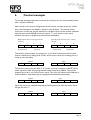
1
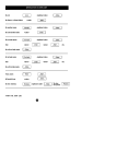
User Guide NFO Sinus fieldbus supplement Profibus, Devicenet & Modbus RTU NFO Drives AB Box 35, SE-376 23 Svängsta, Sweden Tel: +46 (0)454-370 29 Fax: +46 (0)454-32 24 14 Email: [email protected] Internet: www.nfodrives.se Contents 1 Preface..........................................................................................................................................3 2 Introduction ................................................................................................................................3 3 Inverter settings .........................................................................................................................4 3.1 General settings..............................................................................................................4 3.2 Fieldbus specific settings...............................................................................................4 3.2.1 Profibus...............................................................................................................5 3.2.1.1 Fieldbus connector .....................................................................5 3.2.1.2 Termination of fieldbus............................................................5 3.2.1.3 LED indication ..............................................................................5 3.2.1.4 Setting address.............................................................................6 3.2.2 DeviceNet..........................................................................................................6 3.2.2.1 Fieldbus connector .....................................................................6 3.2.2.2 Termination of fieldbus............................................................6 3.2.2.3 LED indication ..............................................................................7 3.2.2.4 DIP switches ..................................................................................7 3.2.3 Modbus RTU .....................................................................................................8 3.2.3.1 Specifications.................................................................................8 3.2.3.2 Fieldbus connector .....................................................................8 3.2.3.3 Termination of fieldbus............................................................8 3.2.3.4 LED indication ..............................................................................8 3.2.3.5 DIP switches ..................................................................................9 4 Configuration of control system ..........................................................................................10 5 Cyclic data.................................................................................................................................10 5.1 Process Data .................................................................................................................10 4.1.1 Control word..................................................................................................10 4.1.2 Status word .....................................................................................................11 4.1.3 Set-point value/Actual value.........................................................................12 6 Control example......................................................................................................................13 NFO Drives AB 2008 Version 1.1 Page 2 1 Preface The data and illustrations found in this document are not binding. We reserve the right to modify our products in line with our policy of continuous product development. The information in this document is subject to change without notice and should not be considered, as a commitment by NFO Drives AB. NFO Drives AB assumes no responsibility for any errors that may appear in this document. 2 Introduction This user guide is a supplement to the regular user and installation manual for the inverter NFO Sinus. It deals with the installation, configuration and management of the inverters delivered with fieldbus option. Communication over the fieldbus in NFO Sinus is solved by using different Fieldbus modules of type AnyBus DataTransfer from HMS Fieldbus Systems. Some information in this guide, Ch. 3.2, is taken from documentation from HMS. Regardless of the Fieldbus selected, NFO Sinus control works in the same way. It follows the "PROFIBUS Profile for variable speed drives”, PROFIDRIVE. The profile describes the various types PPO (Parameter Process Data Object), which indicates different levels of control complexity. At present, NFO Sinus only supports the simplest type PPO, PPO 3, which merely describes the transfer of command, status data, actual values and set-points for speed. NFO Drives AB 2008 Version 1.1 Page 3 3 Inverter settings 3.1 General settings The following parameters affect the functionality of the fieldbus connection. • The parameter "OpMode" should have the value "AnyBus" to allow the inverter to be controlled from the fieldbus. • Choose the PPO type to be used with the parameter "AnyBus". At present only PPO3 is supported. With the right adjustment of these parameters, the inverter will, when restarted, automatically go into the mode of control from the fieldbus. Inverters equipped with fieldbus option will on delivery have such a configuration. The display showing the inverters status is, when controlled via the fieldbus, "Bus Run" or "Bus Stby" depending on whether motor run is activated or not. The display also shows the current motor frequency. Fieldbus control can be cancelled by pressing <STOP> on the keypad, this will immediately release the motor, where after "Stop" shows on the display. Return to fieldbus control by pressing <SHIFT> + <STOP>. Please note that signal RUN must be active and connected to make control through the fieldbus possible. Information on how to set the parameters and activate the RUN signal is given in the ordinary user's guide. 3.2 Fieldbus specific settings The bus connection of the fieldbus module is located on the left side of the inverter (seen from the front). Next to the bus connection are switches for setting the address etc. and LEDs for status indication. This is specific for each fieldbus system. NFO Drives AB 2008 Version 1.1 Page 4 3.2.1 Profibus 3.2.1.1 Fieldbus connector The fieldBus connector consists of a 9-pole female DSUB linked according to Table 1. Contact pin nr 3 4 5 6 8 Contact shield Signal name B-Line RTS GND Vcc A-Line SHIELD Description Data line Request To Send Supply voltage, ground Supply voltage Data line Screen connection Table 1 Fieldbus connector 3.2.1.2 Termination of fieldbus Fieldbus should be terminated at both ends. If the actual inverter is placed in one end point of the bus, put the switch between fieldbus connection and light-emitting diodes(LEDs) in the ON position, otherwise leave it in OFF position. 3.2.1.3 LED indication Three LEDs are stacked in vertical order to the right of the fieldbus connector according to the following table. See function list in Table 2. ERROR DIA POWER LED POWER DIA (Data exchange) ERROR COLOUR Turned off Green Turned Off Green Turned Off Red FUNCTION Power is off Power is on No communication Data Exchange Normal operation Bus off/error Table 2 LED description NFO Drives AB 2008 Version 1.1 Page 5 3.2.1.4 Setting address Two turn switches, located to the right of the LEDs set the unit’s node address. The address may be set in the range 1-99 with steps of ten (10) on the left switch and one (1) on the right switch. 3.2.2 DeviceNet 3.2.2.1 Fieldbus connector The fieldbus connector consists of a terminal with five connections numbered from left to right according to Table 3. Terminal nr 1 2 3 4 5 Signal name VCAN_L SHIELD CAN_H V+ Description Supply 0V Data line , low Screen connection Data line , high Supply +24V DC Table 3 Fieldbus connector 3.2.2.2 Termination of fieldbus Fieldbus should be terminated at both ends. If the actual inverter is placed in one endpoint of the bus, mount a termination resistor in the fieldbus contact between connector 2 and 4, with the value of 120 Ohm. NFO Drives AB 2008 Version 1.1 Page 6 3.2.2.3 LED indication Three square LEDs are vertically aligned to the right of the fieldbus connector according to the following table. See function list in Table 4. NETWORK MODULE POWER LED POWER MODULE STATUS NETWORK STATUS COLOUR Turned off Green Red, flashing Red, solid Green, flashing Green, solid Red, flashing Red, solid Green, flashing Green, solid FUNCTION Power is off Power is on Recoverable fault Critical module fault Configuring Configured and NO module Errors Recoverable fault Critical module fault On-line but not connected On-line, link OK, connected Table 4 LED description 3.2.2.4 DIP switches • Baudrate is set by DIP switch 1 and 2 according to Table 5. • Address is set by DIP switch 3 to 8 according to Table 5. Baudrate bit/s 125k 250k 500k Reserved DIP 1-2 00 01 10 11 Adress 0 1 2 61 63 63 DIP 3-8 000000 000001 000010 111101 111110 111111 Table 5 DIP switch settings (ON = 1) NFO Drives AB 2008 Version 1.1 Page 7 3.2.3 Modbus RTU Modbus RTU is a fieldbus system from the company Modicon, a part of the Schneider Automation. 3.2.3.1 Specifications The media for the fieldbus is a copper cable composed of one twisted pair. The baudrate is as standard 19200 Bit/s but can be modified on the card between 1200 Bit/s to 50 000 Bit/s. The Modbus RTU network can consist of 247 slaves but only one Master. The master always initiates the communication with a question (called a query) and the slave with the right slave address answers the question with a response. 3.2.3.2 Fieldbus connector The fieldbus connector consists of a 9-pole female DSUB linked according to Table 6. Dsub: 1 2 3 4 5 6 7 8 9 PE Function: DE [RS485] RS232 – RX RS232 – TX + 5V Bus Ground Bus RS485 A-line RS485 B-line Not used Not used Shield Table 6 Fieldbus connector 3.2.3.3 Termination of fieldbus When terminating RS485 you have to set the switch located to the right of the fieldbus connector to ON. This is only required when the slave acts as the last slave on the bus and this will prevent an echo of the signal to propagate back on the bus. 3.2.3.4 LED indication Three square LEDs are vertically aligned to the right of the termination switch according to the following table. See function list in Table 7. NFO Drives AB 2008 Version 1.1 Page 8 BUS ERROR BUS ACTIVE POWER Red Green Green Table 7 LED description 3.2.3.5 DIP switches Figur 1 The figure above shows the dip switches on the ModBus RTU module. Table 8 describes the function (‘ON’ is ‘logic zero’ and ‘OFF’ is ‘logic one’). Switch no Function: 0 Electrical communication mode 1-8 Slave address 9 - 11 Baudrate 12 - 13 Parity mode Set value: 0 1 MSB - LSB 000 001 010 011 100 101 110 111 00 01 10 11 Function of set value: RS485 RS232 Valid slave addresses are1 – 247. Addresses outside this range should not be used 1200 2400 4800 9600 19200 38400 50000 Not supported None Odd Even Not used Table 8 DIP switch settings NFO Drives AB 2008 Version 1.1 Page 9 4 Configuration of control system A configuration file is included for the control system, for fieldbus systems which support this. The bus node is to be configured to support the installed PPO-type, see chap. 2. At this time, there is only support for PPO 3 which corresponds to 2 word (4 bytes) cyclical output data and 2 word (4 bytes) cyclical input data. 5 Cyclic data The inverter only supports cyclic data transfer. Data quantity varies after installation of PPO-type and is always of the same size in both output direction (from control system to Inverter) as in input direction (from Inverter to control system). The transferred data quantity consists of parameter data and process data, of which the PPO-type describes the composition. For PPO 3 exsists only process data. 5.1 Process Data Process data is transferred per byte, which are set in pairs to a number of 16-bit words, where the first byte is the most significant (big endian). The first word out, from control system to inverter, is always a so-called “control word” and the next word indicates the set-point value. The first word, from Inverter to control system, describes actual inverter status and the next word is the actual value. 4.1.1 Control word The control word consist of 16 bits in which bit 0 is the least significant, and bit 15 is the most significant bit. See Table 9. NFO Drives AB 2008 Version 1.1 Page 10 Control word Bit Function 0 Run signal 1. A positive edge (0 to 1), provided that bit 1, 2 & 10 are 1-set, and possible errors are cleared, sets the inverter from STOP to RUN mode. If bit 0 is reset while running, the motor will BRAKE, according to the ramp, and after stop, release motor, inverter then goes from RUN to STOP mode. 1 Run signal 2. Must be 1 to enable inverter to go into RUN mode. If bit 1 is reset while in RUN mode, the motor will be RELEASED, and inverter goes from RUN to STOP mode. Then a positive edge (0 to 1) on bit 0 is required to bring the inverter into RUN mode again. 2 Run signal 3. Must be 1 to enable inverter to go into the run mode. If bit 2 is reset while in RUN mode, the motor will BRAKE, and inverter goes from RUN to STOP mode. Then a positive edge (0 to 1) on bit 0 is required to bring the inverter into RUN mode again. 3 Motor output active. Provided that the inverter is in RUN mode, “1” will activate the inverter output, the motor will start running with set-point determined by bit 4-6. If bit 3 is reset while running, motor will be RELEASED. The motor is controlled from ramp generators output. If bit is 1, the set-point of the ramp 4 generators output is used for speed regulation. If bit 4 is reset while running, the motor will decelerate to stop. 5 Ramp generator active. If the bit is 1, the ramp generators output will go towards the value of its input at a rate similar to that of the inverters ramp. If bit 5 is reset while running, the setpoint is frozen, ongoing acceleration or deceleration is stopped and the motor continues to run at current speed. 6 The given set point value linked to ramp generator. If the bit is 1, the programmed set-point value is used as a start value for the ramp generator. If bit 6 is reset while running, the motor will decelerate to stop. 7 Acknowledge of error. If the inverter is blocked due to an error a positive edge (0 to 1) for this bit will acknowledge the error. Provided that the cause of the error is corrected the inverter will then be receptive again for control from the fieldbus. 8-9 8-9 Reserved. Currently not used. Fieldbus control active, process data valid. This bit must be 1 when going from STOP to RUN 10 mode, see bit 0. If the bit is reset during operation, any changes of other process data will be ignored, i.e. the motor continues to run according to previous settings. 11-15 Reserved. Currently not used. Table 9 Control word 4.1.2 Status word The status word consists of 16 bits in which bit 0 is the least significant, and bit 15 is the most significant bit. See Table 10. NFO Drives AB 2008 Version 1.1 Page 11 Status word Bit Value 0 0 1 1 0 2 1 0 3 4 5 6 7-8 9 10 1 0 1 0 1 0 1 0 1 0 1 0 1 11-15 Function The inverter is in stop mode, not ready for run mode. Due to one of the following reasons: 1. The inverter is blocked due to error or is waiting for an error acknowledge, status bit 3 has value 1. 2. Run signal 2 not active; status bit 4 has value 0. 3. Run signal 3 not active; status bit 5 has value 0. 4. The inverter has stopped due to reason 1, 2 or 3 and run signal 1 has not been reset (control bit 0). The inverter is in run mode, or is ready for run mode on positive rise (0 to 1) on run signal 1 (control bit 0). The inverter is not in run mode. If status bit 0 has value 1, then the inverter will go to run mode on positive rise on run signal 1. The inverter is in run mode. The motor output is not activated. If status bit 1 has value 1 then the motor output will be activated by setting control bit 3 to value 1. The motor output is activated. No errors. The inverter is blocked due to error or is waiting for an error acknowledge. Run signal 2 is not active; control bit 1 has value 0. Run signal 2 is active; control bit 1 has value 1. Run signal 3 is not active; control bit 2 has value 0. Run signal 3 is active; control bit 2 has value 1. Run mode allowed. The inverter is stopped and is waiting for run signal 1 to be restored to 0 before the inverter can return to run mode. Reserved, currently not used. The inverter is not available for fieldbus control due to one of the following reasons: 1. Signal RUN on inverter terminal is not activated. 2. The inveter is stopped by pressing the button <STOP>. 3. The inverter is not configured for fieldbus control. The inverter is controlled from fieldbus. Set-point not reached. Actual value and set-point coincide within some tolerance. Reserved, currently not used. Table 10 Status word 4.1.3 Set-point value/Actual value Set-point and actual value is set as an integer in the range –32768 to +32767 which corresponds to –200% to +200% of the inverters maximum frequency, parameter ”Max-fr”. NFO Drives AB 2008 Version 1.1 Page 12 6 Control example This simple example shows how to control the inverter to start the connected motor with a set-point of 50 Hz. After startup and a correct configuration of the inverter and control system, cyclical data are exchanged on the fieldbus, 4 bytes in each direction. The control system sends zeros in both the control word and as set-point value and the inverter responds with the status word 0x0200 and actual value 0. “1” in bit 9 of the status word indicates that input is receptive to control from the fieldbus. Output (from the control system to the inverter) 1 2 3 4 00 00 00 00 MSB LSB MSB LSB Control word Set point Input (from the inverter to the control system) 1 2 3 4 02 00 00 00 MSB LSB MSB LSB Status word Actual value The control system accepts by setting bit 1, 2 and 10 of the control word and the inverter responses by setting bit 0, 4 and 5 of the status word, thus showing that it is ready to start the motor. Output 04 06 Input 00 00 02 31 00 00 The control system now sets bit 0, 3, 4, 5 and 6 and enter set-point as 0x1FFF (8191) which represents 50% of the programmed maximal frequency, 100Hz. The inverter responds to set bit 1 and 2 of the status word. This starts the motor and accelerates it towards 50Hz in accordance with the programmed acceleration parameter. Output 04 7F 1F FF 02 Input 37 00 00 When the motor has reached the programmed frequency, bit 10 in the status word will get the value ”1”. Output 04 NFO Drives AB 2008 7F Input 1F FF 06 37 1F FF Version 1.1 Page 13