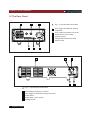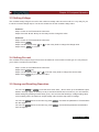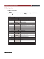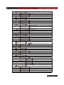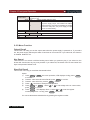
1
USER’S GUIDE
High Resolution and High Speed
Programmable Power Supply
Models IT6100 Series
This user manual is applicable to:
Model: IT6121/IT6122/IT6123
IT6151/IT6152/IT6153/IT6154
Copyright 2009 All Rights Reserved
Ver2.0/Oct, 2009/ IT6100-527
I n t r o d u c t i o n
Chapter1 Quick Reference
...................................................................
5
1.1 The Front Panel
···················································································· 5
1.2 The Rear Panel
···················································································· 6
1.3 Preliminary Checkout
···················································································· 7
1. Check the list of supplied items
··································································· 7
7
2. Connect the power cord and turn on the power supply ··································
3. Checkout Procedure
···················································································· 7
1.4 Output Checkout
···················································································· 8
9
1.5 If the power Supply Does Not Turn On
······························································
1.6 To Adjust the Carrying Handle ···················································································· 10
1.7 To Rack Mount the Instrument ···················································································· 11
1.8 Optional accessory
···················································································· 12
Chapter 2 Specifications
...................................................................... 13
2.1 Specifications
····················································································
IT6120 Series DC Power Supply
······························································
IT6150 Series High Resolution Power Supply
·················································
2.2 Supplemental Characteristics ····················································································
Chapter 3 Front-panel Operation
13
13
14
14
..................................................... 17
3.1Keyboard Disposal
····················································································
Multiple Key Instruction
····················································································
Function Key Instruction ····················································································
3.2 Front-panel Operation Overview ····················································································
3.3 Setting Voltage
·····················································································
3.4 Setting Current
····················································································
3.5 Saving and Recalling Operation
·······························································
3.6 Menu Operation
····················································································
3.6.1 Menu Description
····················································································
3.6.2 Menu Function
····················································································
3.7 Output Operation
····················································································
3.8 Remote Sense
····················································································
3.9 Milliohm Meter
····················································································
3.10 Voltage Meter
····················································································
17
17
18
18
19
19
19
20
20
22
27
27
28
29
Chapter 4 Remote Operation Mode ......................................................... 30
4.1 Communication cable
····················································································
IT-E131 RS232 Communication Cable
······························································
IT-E132 USB Communication Cable
······························································
IT-E135 GPIB Communication Cable
······························································
4.2 Communication between Power Supply and Computer ············································
2
USER’S GUIDE
30
30
30
31
32
About your safety
Please review the following safety precautions before operating our equipment.
General information
The following safety precautions should be observed before using this product and any
associated instrumentations. Although some instruments and accessories would be used
with non-hazardous voltages, there are situations where hazardous conditions may be
present.
This product is intended for use by qualified personnel who recognize shock hazards and
are familiar with the safety precautions required to avoid possible injury. Read and follow
all installation, operation, and maintenance information carefully before using the product.
Refer to this manual for complete product specifications.
If the product is used in a manner not specified, the protection provided by the product may
be impaired.
Before performing any maintenance, disconnect the line cord and all test cables.
Protection from electric shock
Operators of this instrument must be protected from electric shock at all times. The
responsible body must ensure that operators are prevented access and/or insulated from
every connection point. In some cases, connections must be exposed to potential human
contact. Product operators in these circumstances must be trained to protect themselves
from the risk of electric shock. If the circuit is capable of operating at or above 1000 volts, no
conductive part of the circuit may be exposed.
Definition of users
Responsible body is the individual or group responsible for the use and maintenance of
equipment is operated within its specifications and operating limits, and for ensuring that
operators are adequately trained.
Operators use the product for its intended function. They must be trained in electrical safety
procedures and proper use of the instrument. They must be protected from electric shock
and contact with hazardous live circuits.
Service is only to be performed by qualified service personnel.
Safety symbols and terms.
Connect it to safety earth ground using the wire recommended in the user manual.
The symbol on an instrument indicates that the user should refer to the operating
instructions located in the manual.
High voltage danger.
USER’S GUIDE
3
Certification and Warranty
Certification
We certify that this product met its published specifications at time of shipment from the
factory.
Warranty
This instrument product is warranted against defects in material and workmanship for a
period of one year from date of delivery. During the warranty period we will, at its option,
either repair or replace products which prove to be defective. For warranty service, with the
exception of warranty options, this product must be returned to a service facility designated
by us. Customer shall prepay shipping charges by (and shall pay all duty and taxes) for
products returned to the supplier for warranty service. Except for products returned to
customer from another country, supplier shall pay for return of products to customer.
Limitation of Warranty
The foregoing warranty shall not apply to defects resulting from improper or inadequate
maintenance by the Customer, Customer-supplied software or interfacing, unauthorized
modification or misuse, operation outside of the environmental specifications for the product,
or improper site preparation and maintenance. Product number or serial number has been
altered deleted, removed or were unable to identify. Damage from the accident, including but
not limited to lightning, water, fire, abuse or negligence.
Introduction
IT6100 Series power supplies are high resolution and high speed programmable DC power
supplies. This series have very small size of 2U, and they are equipped with 5 12 digital voltage
meter and mΩmeter. That means you don’t need to invest extra money to purchase digital
meter. This series offer flexible solution to general laboratory and workshop requirement.
Convenient bench-top features:
• VFD display
• Liner programmable power supply with low ripple and noise
• Very high accuracy and resolution of 0.1mV/0.1mA
• High rise speed ﹤30mS
• Equipped with 5 12 digital voltage meter and mΩmeter
• Small size can be installed in standard 19’’ rack or bench top
• Remote control via USB/RS232/GPIB
• Limit voltage protection
• Over current/temperature protection
• Free software for remote control the machine on computer
4
USER’S GUIDE
Chapter1 Quick Reference
Chapter1 Quick Reference
1.1 The Front Panel
1
Fig 1.1 IT6120 series’ front panel
1
2
3
4
5
6
7
2
VFD display
Rotary knob
Power switch
Numeric keys and ESC key
Function keys
Up , down key and ENTER key
Output terminals
3
1
3
4
5
4
5
6
7
2
6
7
8
Fig 1.2 IT6150 series’s front panel
1
2
3
4
VFD display
Rotary knob
Power switch
Numeric keys and ESC key
5
6
7
8
Function keys
Up, down key and ENTER key
Voltage measurement terminals
Output terminals
USER’S GUIDE
5
Chapter1 Quick Reference
1.2 The Rear Panel
4
5
Fig 1.3 IT6120 Series’ Rear Panel
6
1
2
3
4
5
6
1
2
8-Pin Trigger and Remote sensing
connectors
9-Pin COM port interface connector
Power switch (110V / 220V)
Cooling window
voltage measurement terminals
Power socket
3
5
4
3
1
Fig 1.3 IT6150 Series’ Rear Panel
1
2
3
4
5
6
USER’S GUIDE
9-Pin COM port interface connector
4-Pin Trigger and Remote sensing connectors
Power socket
Power switch (110V / 220V)
Cooling window
2
Chapter1 Quick Reference
1.3 Preliminary Checkout
The following steps help you to verify that the power supply ready for use.
1. Check the list of supplied items
Verify that you have received the following items with your power supply. If anything is missing,
contact your nearest Sales Office.
□
□
□
□
□
One power cord for your location
One user’s manual
Calibration Report
CD-Rom
Communication cable (optional)
2. Connect the power cord and turn on the power supply
When you turn on the power supply, the front-panel display will light up briefly while the power supply
performs its power-on self-test.
3. Checkout Procedure
If the EEPROM was damaged or the latest
operation data in EEPROM is lost, the VFD
will display as follows:
EEPROM Error
If the calibration data in EEPROM is lost, the
VFD will display as follows:
Error Config Data
If the latest state of the power supply in
EEPROM is lost, the VFD will display as
follows:
Error Calibration Data
If the factory calibration data that saved in
the EEPROM is lost, the VFD will display as
follows:
Error Factory Cal.Data
USER’S GUIDE
7
Chapter1 Quick Reference
If you press the “shift” button when power on
the power supply, the VFD will display the
information of the machine, version of the
firmware and the series number.
Press “Esc” to exit, VFD displays as follows:
The first line is the actual voltage value and
current value, the state of the power supply.
The second line is the voltage value tested by
voltage meter and the setting voltage of the
power supply.
Sourc: XXV XA Meas: XXV
Ver: 1.72 SN:5975002002
0.000V 0.00000A OFF
0.000V 3.000V
Warning: The power supply is shipped from the factory with a power-line cord
that has a plug appropriate for your location. Your power supply is equipped with a
3-wire grounding type power cord; the third conductor being the ground. The power
supply is grounded only when the power-line cord is plugged into an appropriate
receptacle. Do not operate your power supply without adequate cabinet ground
connection.
1.4 Output Checkout
The following procedures check to ensure that the power supply develops its rated outputs and properly
responds to operation from the front panel.
Voltage Output Checkout
The following steps verify basic voltage functions without load.
1)
2)
8
Turn on the power supply.
Enable the outputs.
Press Out On/Off key to let the CV annunciator turn on to light.
USER’S GUIDE
Chapter1 Quick Reference
3)
4)
Set the voltage value.
Set some different voltage values, then wait till the Meter mode to check if the VFD
displayed voltage value is the same as the set voltage value, and to check if the VFD displayed
current value is nearly zero.
Ensure that the voltage can be adjusted from zero to the full rated value.
Current Output Checkout
The following steps check basic current functions with a short across the power supply’s output.
1)
2)
3)
4)
5)
6)
7)
8)
Turn on the power supply.
Disable the output.
Press On/Off key to ensure that the output is disabled.
Connect a short across (+) and (-) output terminals with an insulated test lead.
Use a wire size sufficient to handle the maximum current.
Enable the output.
Adjust the voltage value to 1.0 Volt.
Adjust the voltage to 1.0 Volt to ensure the power supply is in CC operation
mode. The CC annunciator will turn on.
Adjust the current value.
Set some different voltage values, then wait till the Meter mode to check if the VFD
displayed current value is the same as the set voltage value, and to check if the VFD displayed
voltage value is nearly zero.
Ensure that the current can be adjusted from zero to the full rated value.
Turn off the power supply and remove the short wire from the output terminals.
1.5 If the power Supply Does Not Turn On
Use the following steps to help solve problems you might encounter when turning on the instrument. If you
need more help, refer to chapter 6 for instructions on returning the instrument to the supplier for service.
1. Verify that there is AC power to the power supply.
First, verify that the power cord is firmly plugged into the power receptacle on the rear panel of the
power supply. You should also make sure that the power source you plugged the power supply into
is energized. Then, verify that the power supply is turned on.
2. Verify the power-line voltage setting.
The line voltage is set to the proper value for your country (110VAC or 220VAC) when the power
supply is shipped from the factory. Change the voltage setting if it’s not correct.
USER’S GUIDE
9
Chapter1 Quick Reference
3. Verify that the correct power-line fuse is installed.
If the fuse was damaged, please see the table below to replace the fuse for your power supply.
Model
IT6121
IT6122
IT6123
IT6151
IT6152
IT6153
IT6154
Fuse Description(110VAC)
T2.5A 250V
T2.5A 250V
T2.5A 250V
T10A 250V
T10A 250V
T10A 250V
T10A 250V
Fuse Description(220VAC)
T1.25A 250V
T1.25A 250V
T1.25A 250V
T5A 250V
T5A 250V
T5A 250V
T5A 250V
1.6 To Adjust the Carrying Handle
To adjust the position, grasp the handle by the sides and pull outward. Then, rotate the handle to the desired
position.
Bench-top viewing positions
Carrying position
10 USER’S GUIDE
Chapter1 Quick Reference
1.7 To Rack Mount the Instrument
You can mount the power supply in a standard 19-inch rack cabinet using the IT-E151 rack mount kit.
Note: Remove the carrying handle and the two plastic ears before rack-mounting the
instrument. To remove the handle, grasp the handle by sides and pull outwards and rotate
it to a special position to let the arrow on the handle and the arrow on the plastic ears be in
opposite directions, then pull the handle outward. After removing the handle, you can use a
screwdriver to remove the two plastic ears
To rack mount a single instrument, order rack mount kit IT-E151.
To rack mount two instruments side-by-side, order rack mount kit
IT-E151, you needn’t to use the front cover panel.
USER’S GUIDE 11
Chapter1 Quick Reference
IT6150 series power supply rack mount:
IT6150 series’ power supply installation:
IT6150 series power supply can be mounted in standard 19 inch rack, IT-E151 is the accessory we
prepared for customer.
Remove the right and left plastic ears on the power supply , and then put it in the IT-E151,and then
tighten the screws.
Steps:
Step 1
Step 2
the front picture when install IT6150 power supply in IT-E151
101.60
128
465.50
482.60
Unit: milimeter(mm)
1.8 Optional accessory
IT-E151: 19 inch rack mount
IT-E131: RS232 communication cable
12 USER’S GUIDE
IT-E132: USB communication cable
IT-E135: GPIB connector
Chapter 2 Specificationse
Chapter 2 Specifications
2.1 Specifications
IT6120 Series DC Power Supply
Parameter
Output Ratings
( 0 °C~40 °C)
Load Regulation
±(%of output+offset)
Line Regulation
±(%of output+offset)
Programming resolution
Readback resolution
Programming
accuracy, 12months,
(25 °C ± 5 °C)
±(%of output+offset)
Readback accuracy
12months,
(25 °C ± 5 °C)
±(%of output+offset)
Ripple
(20Hz ~20MHz)
Temperature coefficient,
(0 °C~40 °C)
±(%of output+offset)
Readback temperature,
coefficient,
±(%of output+offset)
Dimension(mm)
Weight
IT6121
IT6122
IT6123
Voltage
Current
LVP
Voltage
Current
Voltage
Current
Voltage
Current
Voltage
Current
0 ~20V
0~5A
0 ~21V
<0.01%+2mV
<0.05%+1mA
<0.01%+1mV
<0.05%+0.1mA
0.5mV
0.1mA
0.1mV
0.05mA
0 ~32V
0~3A
0 ~33V
<0.01%+2mV
<0.05%+0.3mA
<0.01%+1mV
≤0.05%+0.05mA
0.5mV
0.02mA
0.5mV
0.01mA
0~72V
0~1.2A
0 ~73V
≤0.01%+2mV
≤0.05%+0.3mA
≤0.01%+2mV
≤0.05%+0.05mA
0.5mV
0.02mA
0.5mV
0.01mA
Voltage
<0.03%+3mV
≤0.03%+6mV
≤0.03%+6mV
Current
<0.05%+2mA
≤0.05%+1mA
≤0.05%+1mA
Voltage
<0.02%+3mV
≤0.02%+5mV
≤0.02%+5mV
Current
<0.05%+2mA
≤0.05%+1mA
≤0.05%+1mA
Voltage
3mVp-p
4mVp-p
5mVp-p
Current
3mArms
3mArms
3mArms
Voltage
<0.02%+3mV
≤0.02%+5mV
≤0.02%+5mV
Current
<0.05%+2mA
<0.05%+0.5mA
≤0.05%+0.5mA
Voltage
<0.02%+3mV
≤0.02%+5mV
≤0.02%+5mV
Current
<0.05%+2mA
≤0.05%+0.5mA
≤0.05%+0.5mA
214.5mmW×88.2mmH×354.6mmD
8 kg
USER’S GUIDE 13
Chapter 2 Specificationse
IT6150 Series High Resolution Power Supply
Parameter
Voltage
Current
LVP
Voltage
Current
IT6151
0~5.2V
0~60A
0~5.5V
<0.01%+0.5mV
<0.1%+10mA
IT6152 IT6153
Line Regulation
±(%of output+offset)
Voltage
<0.02%+0.1mV
<0.02%+1mV
<0.02%+1mV
Curren
<0.1%+1mA
<0.01%+1mA
<0.01%+0.1mA
Programming
resolution
Voltage
0.1mV
1mV
1mV
Current
1mA
1mA
0.1mA
Resdback
resolution
Voltage
0.02%+2mV
<0.02%+6mV
≤0.02%+12mV
Current
<0.1%+30mA
<0.1%+15mA
<0.05%+10mA
Programming accuracy,
12 months
±(%of output+offset)
Readback accuracy
±(%of output+offset)
Ripple
(20Hz~20MHz)
Temperature Coefficient
( 0 °C~40 °C)
±(%of output+offset)
Readback
temperature coefficient
±(%of output+offset)
Dimension(mm)
Voltage
0.02%+1.5mV
0.02%+3mV
0.02%+6mV
Current
<0.05%+15mA
<0.05%+10mA
<0.05%+5mA
Voltage
Current
Voltage
Current
Voltage
4mVp-p
15mArms
0.02%+2mV
<0.1%+30mA
0.02%+2mV
4mVp-p
5mArms
0.02%+5mV
<0.1%+15mA
0.02%+5mV
5mVp-p
3mArms
0.02%+10mV
<0.05%+5mA
0.02%+10mV
Current
<0.1%+30mA
<0.1%+15mA
<0.05%+5mA
Voltage
0.02%+2mV
0.02%+5mV
0.02%+10mV
Current
<0.1%+20mA
≤0.05%+10mA
≤0.05%+5mA
Output Ratings
( 0 °C~40 °C)
The model of remotsense
±(%ofoutput+offset)
0~20V 0~30V
0~27A 0~18A
0~21V 0~31V
<0.01%+1mV
<0.1%+5mA
429mmW×88.2mmH×354.6mmD
Weight
29kg
2.2 Supplemental Characteristics
State Storage Memory
Fifty (50) user-configurable stored states
Recommended Calibration Interval
Once a year
AC Input Ratings (selectable via switch on the rear panel)
Option Opt.01: 220VAC ± 10%, 47 to 63 Hz
Option Opt.02: 110 VAC ± 10%, 47 to 63 Hz
14 USER’S GUIDE
IT6154
0~60V
0~9A
0~61V
<0.01%+1mV
<0.1%+2mA
Chapter 2 Specificationse
IT6121
100W
IT6122
100W
IT6123
100W
IT6151
540W
IT6152
540W
IT6153
540W
IT6154
540W
Cooling
Fan cooled
Operating Temperature
0 to 40 °C
Storage Temperature
-20 to 70 °C.
Environmental Conditions
Designed for indoor use in an installation category II, pollution degree 2 environment. Designed to
operate at maximum relative humidity of 95% and at altitudes of up to 2000 meters.
Dimensions of IT6120 Series: 214.5mmW x 88.2mmH x 354.6mmD
(Unit: mm)
USER’S GUIDE 15
2.2 Specificationse
Dimensions of IT6150 Series: 429mmW×88.2mmH×354.6mmD
434.8
88.2
34.1
455.1
429.1
(Unit: mm)
16 USER’S GUIDE
Chapter 3 Front-panel Operation
Chapter 3 Front-panel Operation
So far you have learned how to install your power supply and do quick start. During the quick start, you were
briefly introduced to operating from the front panel as you learned how to check basic voltage and current
functions. This chapter describes in detail the use of the front-panel keys and shows how they are used to
accomplish power supply operation.
This chapter is divided into the following sections:
Front-Panel Operation Overview,
Setting Voltage
Setting Current
Storing Operation
Menu Operation
On/Off Operation
Remote Sense Function
mΩMeter
5
1
2
Digital Voltage Meter
3.1Keyboard Disposal
11
22
33
Menu
List
Trigger
44
55
66
V/m Ω
0.1W
77
88
Esc
Esc
V-set
V-set
l-set
I-set
00
Save
Save
Recall
Recall
Shift
Shift
On/Off
On/Off
1W
10W
99
·
·
Enter
Enter
Local
Multiple Key
Function Key
Multiple Key Instruction
1
V/mΩ: 5 2 Digital Voltage Meter / mΩ Meter
0.1W: The range of m Meter is 0.1W
1W: The range of mΩ Meter is 1W
10W: The range of mΩ Meter is 10W
USER’S GUIDE 17
3.8 面板操作
Chapter
3 Front-panel Operation
Function Key Instruction
V-set
Set the voltage value
l-set
Set the current value
Save
Save the currently data of the power supply to
internal register
Recall
Recall the data from the internal register
Menu
Set the parameter of power supply
On/Off
Set the output state of power supply
Shift
Use it with multiple key
Up key
Down key
Enter
Press it to confirm
3.2 Front-panel Operation Overview
The following section describes an overview of the front-panel keys before operating your power supply.
1. The power supply is shipped from the factory configured in the front-panel operation mode. At
power-on, the power supply is automatically set to operate in the front-panel operation mode. When
in this mode, the front panel keys can be used.
2. When the power supply is in remote operation mode, you cannot use the front-panel. A change
between front-panel and remote operation modes will not result in any change in the output
parameters. You can change the front-panel and remote operation modes by computer.
3. The output of the power supply can be enabled or disabled from the front panel by pressing
On/Off key.
4. The VFD display shows the present operating status of the power supply with annunciators. Turn
on the power supply, VFD displays two lines data. The first line shows the actual output voltage
value, current value and the state of the power supply. The second line shows the voltage value
tested by the voltage meter and the output value of the power supply.
18 USER’S GUIDE
Chapter 3 Front-panel Operation
3.3 Setting Voltage
The constant voltage range is from 0V to the maximum voltage value of each model. It is very easy for you
to set the constant voltage output. You have 2 solutions to set the constant voltage value.
Solution1:
Step1: Power on the IT6100 series instrument
Step2: Press the ▲ and ▼ keys or the rotary knob to change the value
Solution2:
Step1: Power on the IT6100 series instrument
Step2: Press V-set
Step3: Use the numeric keys 0 to 9 or the rotary knob to change the voltage value.
Step4: Press Enter to confirm.
3.4 Setting Current
The constant current output range is from 0A to the maximum current value of each type. It is very easy for
you to set the constant current output.
Step1. Power on the IT6800 series instrument
Step2. Press l-set key
Step3. Use the numeric keys 0 to 9 or use the rotary knob to change the current value
Step4. Press Enter key to confirm the value
3.5 Saving and Recalling Operation
You can use Save or Recall or use the SCPI order *SAV、*RCL to store up to 50 different output
states in storage register locations(1 to 50). If the fast recall function is turned on, you can recall the
saved settings by pressing numerical key (0~9). You can store the followings: voltage setting value,
current setting value, the maximum output voltage value, and the step value of voltage.
You can use Save and 0~50 numeric key,press
into the register.
You can use Recall and 0~50 numeric key, press
from the register.
Enter
, and store the parameter of IT6100 series
Enter
, and recall the parameter stored before
USER’S GUIDE 19
3.8 面板操作
Chapter
3 Front-panel Operation
3.6 Menu Operation
3.6.1 Menu Description
Press Menu to indicate operation mode. View the menu in VFD, and use ▲ and ▼to scroll
through the complete menu list as following. If press Enter , you could get the selected menu
function. Press Esc back to the previous menu selection page.
MENU
Config
Config Init.
Out Recall
Return to the factory default setup value.
Setting Power-on state of power supply.
When users turn on the power supply; its setup
On
value will keep the state of last time as users turned
off the power supply.
Off<Default>
Disable this function.
PWR-ON Recall
Setting power-on parameter of power supply
When users turn on the power supply; its setup
On
value will keep the state of last time as users turned
off the power supply.
Off<Default>
Disable this function.
Key Sound Set
Keypad sound setting.
On<Default>
Enable key sound.
Off
Disable key sound
Knob Lock Set
Setup Rotary knob lock state.
On
Lock Rotary knob.
Off< Default >
Unlock Rotary knob.
Remote Sense
Setup voltage measurement Mode.
The power supply will measure output voltage from
On
the remote sense connector.
The power supply will measure output value from
Off< Default >
the front panel connector.
ShortCut Recall
Quickly recall the data stored before
On
Enable this function
Off<Default>
Disable this function
Baudrate set
Setting baud rate
Baudrate 4800 <
Default >
Baudrate 9600
Baudrate 19200
Baudrate 38400
20 USER’S GUIDE
Chapter 3 Front-panel Operation
Comm. Parity
Communication parity bit set
None< Default >
Even
Odd
Address Set
Setting communication address(range from 0to 254)
Address= ﹡﹡
Port Mode
Select function of port
Trigger< Def >
RI/DIF
DIGITAL I/O
Trig Source
Setting trigger mode
Immediat<Def>
Trigger signals from Shift
+ Trigger
key
Trigger signals from the TRIG connector in the rear
External
panel.
Bus
Communication command trigger mode.
RI Mode
Control the output mode
Off< Default >
Disable this function
Latching
Live
DFI Source
Discrete Fault Indicator
Off< Default >
QUES
Question Bit
OPER
Operation Bit
ESB
Event State Bit
RQS
Require Bit
Setting keypad password.
Key Lock Set
Press Enter directly to disable the key lock function.
Password= ﹡﹡﹡﹡
Exit
System Set
Max Volt. set
Setup the Maximum Voltage.
Max= ﹡﹡﹡﹡
Step Volt Set
Set voltage step
Step=﹡﹡﹡﹡
Exit
List Set
Call ListFile
Recall list operation file.
Edit ListFile
Edit list operation file.
Continuous
Once
Repeat
Step
Once
Repeat
Users can choose 4 kinds of memory space to save the list
Save Mode Set
file.
8 X 25 Steps
4 X 50 Steps
2 X 100 Steps
1 X200 Steps
Exit
USER’S GUIDE 21
3.8 面板操作
Chapter
3 Front-panel Operation
Output timer,if you start this function, the power supply will turnoff after
the time you set.
Timer State
Setting POWER ON timer state
When users choose the timer state ON, then turn on
the power supply output, the POWER ON TIMER
On
will start working, and when the POWER ON TIMER
is reach the setup time, the power supply's output
will turn off automatically,.
Off< Default >
Timer Set
Setting time of POWER ON timer.
Timer= ﹡﹡S
Exit
Out On Timer
Exit
3.6.2 Menu Function
Output Recall
This function can help you set the output state when the power supply is powered on. If you select
On, the power supply will keep the state of last time as it is turned off. If you select Off, this function
is disabled. Default is On.
Key Sound
This instruction can switch on/off the buzzing sound when you press any key, if you select On, the
buzzer will sound when any key was pressed. If you select Off, the buzzer will not sound when the
keys were pressed. Default is On.
ShortCut Recall
This function can help you recall the data stored before.
Option:
Enter
1) Press Shift + Menu into menu operation, VFD displays Config, press
to confirm.
2) Press▲、▼to select ShortCut Recall, press Enter to confirm.
3) Press▲、▼to select On, press to Enter confirm.
4) Press Esc two times to escape menu operation.
l-set
5) Press V-set or
, select 0 to 9 to set voltage value or current value,
press Enter to confirm.
6) Press Save , VFD displays Store 1, select 0 to 9 to set the register
number(range from 1 to 50), press Enter
to confirm.
You can recall the data stored before by pressing the register number.
22 USER’S GUIDE
Chapter 3 Front-panel Operation
Setting Communication Baud Rate (>BAUDRATE)
This function can help you set communication baud rate. There are 4 kinds of baud rate, 4800HZ,
9600HZ, 19200HZ and 38400HZ. Make sure that power’s baud rate is as the same as your
computer before communication. Default baud rate is 4800HZ.
Setting Address (>ADDRESS)
This instruction can set the communication address for each power supply. The address range is
from 0 to 30. Before the communication, you must make sure that there is same address between
the power supply and the computer. Default address is 0.
Option:
1)
Press Shift + Menu into menu operation, VFD displays Config, press
to confirm.
2)
Press▲、▼to select Address Set, press Enter to confirm.
3)
VFD displays Address=﹡﹡, select 0 to 9 and set address, press Enter
to confirm.
4)
Press Esc two times to escape menu operation.
Enter
Port Mode
The level of the port on the rear panel is TTL, and the port has 3 kinds of function as follows:
TRIGGER: pin1 and pin 2 can be used as the external trigger source for power supply,
and can control the list operation.
RI/DFI: Inhibit Input can control the output state of power supply, Fault Output can find
fault of power supply.
DIGITAL I/O: It can read and control output and input state.
USER’S GUIDE 23
3.8 面板操作
Chapter
3 Front-panel Operation
Pinmode
1
2
3
4
Trigger
RI/DFI
Digital I/O
Trigger in
GND
No Use
No Use
Inhibit Input
GND
Fault Output
GND
Digital Input
GND
Digital Output
GND
Trigger Operation (Shift+Trigger)
The power supply has 3 kinds of trigger mode. You must choose trigger source before trigger
operating.
Trigger Key: If this function is enabled, press Shift
+ Trigger , the power supply will
start trigger operation once.
External trigger signal(TTL): There is a trigger input port on the rear panel. When this
function is enabled, please give this trigger input port a pulse about 5 mS, and the power
supply will start trigger operation once.
Bus: When this function is enabled, and the power supply receives order*TRG or
TRIgger, the power supply will start trigger operation once.
Remote Inhibit
RI input has 3 modes: LATCHING,LIVE,OFF
LATCHING: When the level of RI port changes from high to low, the output of power
supply is off.
LIVE: The output state of power supply changes along with the level of RI port. If the
level of RI is
high, the output is on; and the level of RI is low, the output of power supply is off.
OFF: The level state of RI do not affect the output state of power supply.
Discrete Fault Indicator
DFI source contains QUES,OPER ,ESB,RQS,OFF.
QUES: The output level of DFI changes along with the state of QUES bit. When QUES
bit is 1, DFI
outputs low level. When QUES bit is 0, DFI outputs high level.
OPER: The output level of DFI changes along with the state of OPER bit.
ESB: The output level of DFI changes along with the state of ESB bit.
RQS: The output level of DFI changes along with the state of RQS bit.
OFF: The output level of DFI remains high.
24 USER’S GUIDE
Chapter 3 Front-panel Operation
KEY LOCK
This instruction can set a password (1 through 4 digits) to lock the function keys operation. After
setting the password, all the function keys on the front panel will be locked except the OUT on/off
key. You must enter the correct password to unlock them, then you can continue to do the function
key operation. If you don’t want to lock the function keys, please don’t press any number key when
you enter the >KEY LOCK instruction, just press ENTER key to unlock it.
Note: When shipped from factory, there is no password and function keys are unlocked.
The start bit of your desired password shouldn’t be 0.
List Set
Before you edit the list file, please set trigger source as “immediate” in the menu.
Action:
1)
Press Shift + Menu into the menu.
2)
Press up or down key to select “Config”, press to confirm.
3)
Press up or down key to select “Trig Source”, press to confirm.
4)
Press up or down key to select “Immediat”, press to confirm.
You can make the input change order by editing every step value of list operation. The parameter
of list operation includes the name of list file, input step (no more than 200 steps), step time (the
minimum is 1mS) and every step value. The list file can be stored in ROM whose capacity is 4K, and
it can be fast recalled. This store area is divided into A, B, C and D four areas. In area A, there is
only 1 group whose capacity is 4Kb. In area B, there are 2 groups and each group’s capacity is 2Kb.
In area C, there 4 groups and each group’s capacity is 1Kb. In area D, there are 8 groups and each
group’s capacity is 512b.
Operation:
1)
Press Shift + Menu into menu operation.
2)
VFD displays Config, press▼to select List Set, press Enter to confirm.
3)
VFD displays Call ListFile, press▼to select Edit ListFile, press Enter to confirm.
4)
VFD displays Continuous, press Enter to confirm.
5)
VFD displays Once, press▼to select Repeat, press Enter to confirm, select
circle operation.
6)
VFD displays Second, press▼to select MilliSecond, press Enter to confirm,
select time unit.
7)
VFD displays List Count= _, press numeric key or use the rotary knob, set
circle times( in this example, count is 2), press Enter to confirm.
USER’S GUIDE 25
3.8 面板操作
Chapter
3 Front-panel Operation
8)
9)
10)
11)
12)
13)
14)
15)
16)
VFD displays1th=﹡.﹡﹡﹡﹡V, press numeric key or move the rotary knob, set the
maximum voltage, press Enter to confirm.
VFD displays 1th=﹡.﹡﹡﹡﹡A, press numeric key or move the rotary knob, set the
maximum current, press Enter to confirm.
VFD displays 1th=﹡mS, press numeric key or move the rotary knob, set delay
time, press Enter to confirm.
VFD displays 2th=﹡.﹡﹡﹡﹡V, press numeric key or move the rotary knob, set the
maximum voltage, press
to confirm.
Enter
VFD displays 2th=﹡.﹡﹡﹡﹡A, press numeric key or move the rotary knob, set the
maximum current, press Enter to confirm.
VFD displays 2th=﹡mS, press numeric key or move the rotary knob, set delay
Enter
time, press
to confirm.
VFD display Store File_, press numeric key or move the rotary knob, set the
register number(1 to 8), press Enter to confirm.
Press Esc two times to escape menu operation.
Shift
List
Press
+
to set the list file, then press Shift + Trigger to run
List
Shift
the list file. Press
+
to stop.
If the list operation mode is
CONTINIOUS, when you receiving
a trigger signal, the power supply
will start list operation until the list
operation is over or a trigger is
received again.
Trigger
Trigger
Trigger
Trigger
When the list operation mode is
STEP, the power supply will go
to the next step when receive a
trigger signal.
Trigger
Trigger
Trigger
Trigger
Trigger
Trigger
Digital I/O
Trigger
Trigger
Trigger
Trigger
Trigger
Trigger
Trigger
Trigger
Trigger
Trigger
When the digital port of the power supply mode is DIGITALI/O and power supply is under remote
sense, you could send SCPI order (DIGital:INPut[:STATe?] and DIGital:OUTPut[:STATe?])to read and
set the state of output and input port.
26 USER’S GUIDE
Chapter 3 Front-panel Operation
3.7 Output Operation
If you control the power supply by front panel, you can press and switch the state of output. If power supply
is under remote sense, you can send SCPI order (OUTPut ON|OFF) to change the state of output.
3.8 Remote Sense
The wire connected the power supply and electronic load will produce voltage difference when the current
of the power supply is so big. In order to make the measurement accuracy much accurate, there are 4 pin
trigger and remote sensing connectors on the rear panel and you can use it to measure the output voltage of
the tested instrument. You must set remote sense mode before you start remote test function.
IT6120 8 pin connector on rear panel
+
-
+S
-S
INH GND FLT GND
+,-: Output port, they are as the same as the output in front panel
+S,-S: Sense port
INH: this port has multiple function
When “Port Mode” in the menu is set with “Trigger”, INH is trigger port.
When “Port Mode” in the menu is set with “RI/DIF”, INH can set the output status on/off. Here INH
port has 3 working mode to choose.
LATCHING: When the level of INH port changes from high to low, the output of power supply is off.
LIVE: The output state of power supply changes along with the level of INH port. If the level of INH is
1, the output is on; and the level of INH is 0, the output of power supply is off.
OFF: The level state of INH do not affect the output state of power supply.
When “Port Mode” in the menu is set with “DIGITAL I/O”, INH port becomes the digital input port to
read input status by communication order.
FLT: this port hat multiple function
When “Port Mode” in the menu is set with “Trigger”, FLT is an invalid port.
When “Port Mode” in the menu is set with “RI/DIF”, FLT port can find fault of power supply.
FLT source contains QUES, OPER, ESB, RQS, OFF.
QUES: The output level of FLT changes along with the state of QUES bit. When QUES bit is 1, FLT
outputs low level. When QUES bit is 0, FLT outputs high level.
OPER: The output level of FLT changes along with the state of OPER bit.
ESB: The output level of FLT changes along with the state of ESB bit.
RQS: The output level of FLT changes along with the state of RQS bit.
OFF: The output level of FLT remains high.
When “Port Mode” in menu is set with “DIGITAL I/O”, FLT port becomes output port to control the
output status by communication order.
USER’S GUIDE 27
3.8 面板操作
Chapter
3 Front-panel Operation
IT6150 4 pin connector on rear panel
GND TRIN
-
+
GND,TRIN: Trigger port
-,+: Remote sense port
3.9 Milliohm Meter
SOURCE METER can measure resistant value accurately and the biggest resistance it can measure is 1kΩ.
In order to protect the resistor, please select the power range of the resistor before you measure it. Wiring
diagram as follows:
There are 3 ranges to be chosen: 0.1W、1W、10W.
The accuracy of the measurement is <1%, the higher range you select, the more accurate result you
can get.
Option:
1)
Press Shift +V/m ( if VFD displays﹡﹡.﹡﹡V, press Shift +V/m ), set m:﹡﹡, you can measure
resistance value.
2)
Press Shift +0.1W /1W /10W, you can set different range of milliohm meter.
28 USER’S GUIDE
Chapter 3 Front-panel Operation
3.10 Voltage Meter
Wiring diagram as follows:
5 ½ DVM
+
LOAD
-
+
-
Press +V/m (if VFD displays Range: ﹡﹡,please press +V/m ), VFD displays﹡﹡.﹡﹡V, you can begin to
test the voltage value.
The accuracy is <0.1%.
USER’S GUIDE 29
Chapter 4 Remote Operation Mode
Chapter 4 Remote Operation Mode
The DB9 interface connector on the rear panel of the power supply can be transferred to RS-232 interface,
the following information will tell you how to use the computer to control the output of the power supply.
4.1 Communication cable
IT-E131 RS232 Communication Cable
The DB9 interface connector on the rear panel of power supply is TTL voltage level; you can use the
communication cable (IT-E131) to connect the DB9 interface connector of the power supply and the
RS-232 interface connector of computer for the communication.
Computer side
TTL→RS232 Cable (IT-E131)
PS side
IT-E131
IT-E131communication
communicationcable
cable
PC
PC
COMPUTER
IT
RS232
IT-E131 ISOLATED
COMMUNICATION CABLE
ISOLATION
TTL(5V)
859666668889942311
RX
TX
INSTRUMENT
PC
Power
Power
supply
Load
supply
IT-E132 USB Communication Cable
The DB9 interface connector on the rear panel of power supply is TTL voltage level; you can use the
communication cable (IT-E132) to connect the DB9 interface connector of the power supply and the
USB interface connector of computer for the communication.
30 USER’S GUIDE
Chapter 4 Remote Operation Mode
IT-E131
IT-E132communication
communicationcable
cable
PC
PC
COMPUTER
IT
RS232
IT-E131 ISOLATED
COMMUNICATION CABLE
ISOLATION
TTL(5V)
859666668889942311
RX
TX
INSTRUMENT
PC
Power
Power
supply
Load
supply
IT-E135 GPIB Communication Cable
The DB9 interface connector on the rear panel of power supply is TTL voltage level; you can use the
GPIB communication cable (IT-E135) to connect the DB9 interface connector of the power supply,
and then connect the GPIB interface of the IT-E135 and computer with GPIB/IEEE 488 line for the
communication.
IT-E135 outer communication adapter
IT-E135 outer communication adapter
COM
of
COM interface
interface of
Power
supply
Power supply
GPIB
line
GPIB line
IT-E135 ISOLATED
ISOLATED
IT-E135
Serial
/IEEE
Serial /IEEE 488
488 Controller
Controller
Note: Forbidden to connect DB9 connector in power supply directly with PC or other
RS232 port.
USER’S GUIDE 31
Chapter 4 Remote Operation Mode
4.2 Communication between Power Supply and Computer
Before using the remote operation mode, please make sure that the baud rate and communication address
in power supply are the same as in the computer software, otherwise, the communication will fail, you can
change the baud rate and communication address from the front panel or from computer.
1.
2.
3.
4.
5.
Address: the range is from 0 to 254, default setting is 0
Baud rate: 4800,9600,19200 and 38400 are selectable, default setting is 4800
Data bit: 8 bit
Stop bit: 1
Parity: None
Parity=None
1.
2.
Start Bit
8 Data Bits
Stop Bit
Stop Bit
End of String is ’\n’(0x0a)
DB9 Interface Details
DB9 in the rear panel of power supply is TTL level signal. It can be connecting with standard PC
interface through the isolated communication cable.
32 USER’S GUIDE
ITECH Electronic Co.,Ltd
China
Tel : 025-52415098
Fax: 025-52415268
310# Ning Nan Da Dao,
NanJing City, 210012, Jiangsu
Province,China
Europe
Tel : 477-590101
Fax: 477-572323
32, rue Edouard Martel
42100 - St Etienne France
USA
Tel : 714-9219095
Fax: 714-9216422
22820 Savi Ranch Parkway
Yorba Linda, CA 92887 U.S.A.
South Korea
Tel : 285-20680
Fax: 285-20684
#153-783,Rm601,ByuckSan,
GaSan-Dong, Seoul, Korea