1
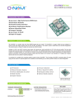
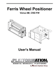
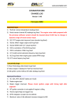
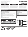
Guardmaster Safety Relay GLP
10000335607 ver 00, Dwg. No: 95302416, Issue 1, EO: 0412, August 2012
Quick Start Guide - Troubleshooting
Schnellstart - Diagnosehilfe
Inicio rápido - Ayuda de diagnóstico
English
GENERAL NOTES
The illustrations, charts, sample programs and layout
examples shown in this guideline are intended solely for
purposes of example. Since there are many variables and
requirements associated with any particular installation,
Rockwell Automation does not assume responsibility or
liability including intellectual property liability, for actual
use based upon the examples shown in this publication.
Deutsch (original)
Español
ALLGEMEINE HINWEISE
Die Abbildungen, Diagramme und Aufbaubeispiele in dieser Richtlinie dienen ausschließlich zur Veranschaulichung.
Aufgrund der vielfältigen Anforderungen der jeweiligen
Applikation kann Rockwell Automation keine Verantwortung oder Haftung (einschließlich Haftung für geistiges
Eigentum) für tatsächlichen Einsatz auf der Grundlage
dieser Beispiele übernehmen.
INDICACIONES GENERALES
Las ilustraciones, diagramas y ejemplos de estructuración
en esta directiva sirve exclusivamente para demostración.
En función de la multiplicidad de requerimientos de las
correspondientes aplicaciones Rockwell Automation
no puede asumir ninguna responsabilidad o garantía
(incluyendo garantía de propiedad intelectual) para la
aplicación efectiva sobre la base de estos ejemplos.
Drawings / Zeichnungen / Gráficos
Connections / Anschlüsse / Conexiones
LED Indication / LED Anzeigen / Indicadores LED
A1, A2
S12, S22
X14, X24
PWR/FAULT
Status and Diagnostics / Status und Fehleranzeige / Estado e indicador
de fallos
IN1
Status of safety output IN1 / Status des Sicherheitseingangs IN1 / Estado de
la entrada de seguridad IN1
LOCK
Lock Status / Status Verriegelung / Estado bloqueo
LOGIC IN
Status of dynamic input / Status des dynamischen Sicherheitseingangs /
Estado de la entrada de seguridad dinámica
OUT
Status of safety outputs L11, X14, X24 / Status der Sicherheitsausgänge L11,
X14, X24 / Estado de las salidas de seguridad L11, X14, X24
AP
P12, P22
S44
S54
Y32
L12
L11
L61
51
Power / Spannungsversorgung / Alimentación
IN1: Safety input / Sicherheitseingang / Entrada de seguridad
Test outputs for safety inputs or safety outputs / Eingangsseitige Testausgänge oder Sicherheitsausgänge / Salidas de
prueba para entradas de seguridad o Salida de seguridad
Power Supply for Speed sensors (Proxes) / Versorgungsspannung Geschwindigkeitssensoren / Tensión de alimentación
Sensores de velocidad
Speed sensor inputs (Prox) / Eingang Geschwindigkeitssensoren (PNP) / Entrada sensores de velocidad (PNP)
Monitoring feedback loop incorporating reset button and lock request / Rückführkreis inkl. Rücksetzeneingang und
Verriegelungssignal / Circuito de realimentación incluida entrada de reinicio y señal de bloqueo
Unlock request / Freigabeanforderung / Requerimiento de desbloqueo
Auxiliary PNP semiconductor output / PNP-Halbleiterhilfsausgang / Salida de semiconductor PNP auxiliar
Single wire safety input / Dynamischer Sicherheitseingang (Einzeldraht) / Entrada de seguridad de un solo cable
Single wire safety output / Dynamischer Sicherheitsausgang (Einzeldraht) / Salida de seguridad de un solo cable
Single wire safety output, Lock / Dynamischer Sicherheitsausgang (Einzeldraht), Freigabe / Salida de seguridad de un solo
cable, Desbloque
Lock Output / Freigabe-Ausgang / Salida de desbloque
Circuit Diagram / Anschlussdiagramm / Diagrama de circuitos
Dimensions / Abmessungen / Dimensiones
mm (in)
Installation / Installation / Instalación
Mount in enclosure to a min of IP54.
Einbau in Gehäuse nach mind. IP54.
Montar en envolvente a un mínimo de IP54.
Removable terminals To remove, insert screwdriver and slowly move as shown.
Abnehmbare Klemmen Zum Abnehmen der Klemmen, Schraubendreher langsam, wie dargestellt,
einsetzen.
Terminales extraíbles Para retirar, coloque un destornillador y muévalo lentamente como se indica.
Diagnostics
Diagnose
Diagnósticos
The LED indicators on the front face provide diagnositic
information. In some cases, the PWR/Fault indicator blinks
only red
. In some cases, the PWR/Fault indicator is
green
and flashes red
. The flash sequence pauses
2 sec before repeating.
Die LEDs auf der Front zeigen den Gerätezustand an. Zur
Fehlerdiagnose werden Blinkfrequenzen angezeigt. Je
nach Fehlerart blinkt die PWR/Fault LED nur rot
oder
abwechselnd rot
und grün
. Die Blinksequenz wird
nach 2 Sekunden Pause wiederholt.
Las LED frontales indican el estado del dispositivo. Para
el diagnóstico de los errores se indican frecuencias de
parpadeo. Según el tipo de error parpadea la LED PWR/
Fault solo en rojo
o alternativamente en rojo
y en
verde
. La secuencia de parpadeo se repite después de
2 segundos de pausa.
PWR / FAULT
2x
3x
4x
5x
PWR / FAULT
STATUS / STATUS / E STADO
RESET / RÜCKSTELLUNG / RESET
Normal Operation, no fault
Cycle power
The actual configuration, rotary switches and jumpers do not match the EEPROM. Relay will function normally.
Configuration has been changed during operation:
Adjust rotary switch back to target position and reconfigure
jumpers
Close safety circuit and Reset again
-
Lock command/Reset has been initated while safety input circuit S12, S22 open
-
Speed exceeded maximum speed limit SL2
Slow down speed below, speed limit SL2 and sequentially
press S54 and S44
Slow down speed below, speed limit SL2 and sequentially
press S54 and S44
Speed exceed maximum speed limit SL1
FAULT MODE / FEHLERMODI / MODO DE ERRORES
RESET / RÜCKSTELLUNG / RESET
Non-recoverable fault.
A) If unit comes back healthy: check potential sources for EMC distrubance in the related system around GLP
B) If unit remains in same fault state: Potential internal fault.
Cycle power
Speed monitoring fault. Both Proximity inputs are LOW simultaneously: Potential missalignment of Proximity Sensors e.g. exceeding max.
sensing distance, both sensors facing a space
Align Proximity Sesnors and cyle power
1x
2x
3x
Remove fault and cycle power
4x
5x
6x
Self test of single wire safety outputs L11, L61 failed: Check connections of L11 and L61 against shorts to 24V or 0V and cross loop shorts.
If unit remains in same fault state: Potential internal fault.
Self test of X14, X24 failed: Check connections of X14 and X24 against shorts to 24V or 0V and cross loop shorts.
If unit remains in same fault state: Potential internal fault.
Remove fault and cycle power
Remove fault and cycle power
Remove fault and cycle power
7x
8x
Proximity Input fault, stuck at LOW or HIGH: Potential damage or missalignment of Proximity Sensors e.g. exceeding max. sensing distance,
both sensors facing a space
Remove fault and cycle power
9x
Self test of 51, L61 failed: Check guard locking connections of 51 and L61 against shorts to 24V or 0V and cross loop shorts.
If unit remains in same fault state: Potential internal fault.
Remove fault and cycle power
Over voltage
Remove fault and cycle power
10x
10000335607 ver 00, Dwg. No: 95302416, Issue 1, EO: 0412, August 2012
Copyright ©2012 Rockwell Automation, Inc. All Rights Reserved. Printed in Germany.