1
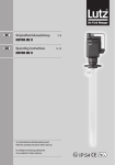
D GB Betriebsanleitung Druckluftmotore MD-1 / MD-2 / MD-3 Operating Instructions Compressed air motor MD-1 / MD-2 / MD-3 Vor Inbetriebnahme Betriebsanleitung lesen! Read this operating instructions before start up! Für künftige Verwendung aufbewahren. To be retained for future reference. 3–8 9–14 Bild/Fig. 1 (MD-1) Bild/Fig. 2 (MD-2) Bild/Fig. 3 (MD-3) Bild/Fig. 4 Bild/Fig. 5 Bild/Fig. 6 Bild/Fig. 7 D Inhalt 1. Allgemeines������������������������������������������������������������������������������������������������������������������������������4 1.1 Lieferumfang��������������������������������������������������������������������������������������������������������������������4 2. Motorvarianten�������������������������������������������������������������������������������������������������������������������������4 3. Inbetriebnahme������������������������������������������������������������������������������������������������������������������������5 3.1 Druckluftanschluss�����������������������������������������������������������������������������������������������������������5 3.2 Montage am Pumpwerk���������������������������������������������������������������������������������������������������6 3.3 Prüfen des Ex-Schutzes����������������������������������������������������������������������������������������������������6 4. Bedienung��������������������������������������������������������������������������������������������������������������������������������6 4.1 Druckluftmotor MD-1 starten�������������������������������������������������������������������������������������������6 4.2 Druckluftmotor MD-2 starten�������������������������������������������������������������������������������������������6 4.3 Druckluftmotor MD-3 starten�������������������������������������������������������������������������������������������6 5. Reparaturen������������������������������������������������������������������������������������������������������������������������������6 6. Einsatz im explosionsgefährdeten Bereich�������������������������������������������������������������������������������7 6.1 Potentialausgleich und Erdung�����������������������������������������������������������������������������������������7 6.2 Vorschriften zum Explosionsschutz����������������������������������������������������������������������������������7 6.3 Zoneneinteilung für explosionsgefährdete Bereiche���������������������������������������������������������8 6.4 Erläuterung der Zoneneinteilung bei der Anwendung von Fasspumpen für brennbare Flüssigkeiten������������������������������������������������������������������8 6.5 Rückverfolgbarkeit�����������������������������������������������������������������������������������������������������������8 Konformitätserklärung.....................................................................................................15 D Allgemeine Sicherheitshinweise 1. 2. 3. 4. 5. 6. 7. Die Betriebsanleitung ist vor Inbetriebnahme vom Bediener des Motors zu lesen und die Hinweise sind während des Betriebs einzuhalten. Die bestimmungsgerechte Gebrauchslage des Motors ist senkrecht. Prüfen Sie ob der Motor ausgeschaltet ist, bevor Sie die Druckluft anschließen. Beachten Sie, dass alle Anschlüsse und Verbindungen richtig befestigt sind. Motor nicht ohne Pumpwerk betreiben. Der Motor darf nicht in die Förderflüssigkeit getaucht werden. Je nach Einsatzbedingungen kann der Schalldruckpegel 85 dB(A) überschreiten. Ab diesem Wert muss Gehörschutz getragen werden. Instandsetzung nur durch den Hersteller. Die Einstufung brennbarer Flüssigkeiten erfolgt nach Richtlinie 67/548/EWG. Beim Fördern brennbarer Flüssigkeiten sind die Betriebssicherheitsverordnung und die nachfolgenden Punkte zu beachten: 1. Druckluftmotore sind nichtelektrische Betriebsmittel und unterliegen beim Einsatz in Zone 1 keiner Zulassungspflicht. 2. Die Druckluftmotore MD1, MD2, und MD3 entsprechen der Richtlinie 94/9/EG ( Gruppe II, Kategorie 2 für Gase). 3. Die Motore sind damit geeignet zum Antrieb von Lutz Fass- und Behälterpumpen der Gerätekategorie 1/2. 4. Die Beschränkungen des Einsatzes werden durch das Pumpwerk (s. Betriebsanleitung) vorgegeben. 5. Nur ortsveränderlicher Einsatz zugelassen. 6. Motor nur mit explosionsgeschütztem Pumpwerk betreiben. 7. Potentialausgleich herstellen. 8. Nur leitfähige Druckschläuche verwenden. 9. Pumpenmotor muss außerhalb des ortsveränderlichen Gefäßes sein. 10.Betriebsdruck nicht überschreiten. 11.Der Betrieb von Motor und Pumpe ist zu überwachen. 12.Motor zu Pumpwerk nur im Stillstand kuppeln. 13.Motor nicht mit brennbaren Gasen betreiben. 14.Vorgeschriebenes Wartungsintervall: Rillenkugel lager und Schieber sind spätestens nach 2.000 Betriebsstunden gemeinsam zu wechseln. Die Unfallverhütungsvorschriften des jeweiligen Landes sind unbedingt einzuhalten. 1. Allgemeines Eine Fass- und Behälterpumpe mit Druckluftantrieb besteht aus dem Motor und einem je nach dem Einsatzfall passenden Pumpwerk. Der Einsatz der Druckluftmotoren MD-1, MD-2 und MD-3 in explosionsgefährdeten Bereichen oder zum Fördern brennbarer Flüssigkeiten ist nur in Verbindung mit einem Pumpwerk erlaubt, das für Kategorie 1/2 G zugelassen ist. Dies sind die Lutz-Pumpwerke aus Edelstahl (Niro 1.4571) und Hastelloy C (HC). 1.1 Lieferumfang Prüfen Sie die Lieferung mit Hilfe Ihrer Bestellung auf Vollständigkeit. 2. Motorvarianten Druckluftmotoren sind nichtelektrische Betriebsmittel und unterliegen beim Einsatz in Zone 1 keiner Zulassungspflicht. Die Druckluftmotoren MD-1 (Bild 1) und MD-2 (Bild 2) sind in Anlehnung an EN 50014 (für elektrische Betriebsmittel) gebaut und können zum Fördern brennbarer Flüssigkeiten, die zu den Explosionsgruppen IIA und IIB und zu den Temperaturklassen T1 bis T4 gehören, aus ortsbeweglichen Behältern1 verwendet werden. Der Druckluftmotor MD-3 (Bild 3) ist zusätzlich druckfest gekapselt und entspricht in Anlehnung an EN 50014 der Kennzeichnung Ex d IIC T6. Auch dieser Motor darf nur zum Fördern brennbarer Flüssigkeiten aus ortsbeweglichen Gefäßen verwendet werden. Typ MD-1 MD-2 Abgabeleistung MD-3 400 W Max. Betriebsdruck 6 bar Luftverbrauch2) 0,88 Nm³/min Explosionsgruppe1) IIA, IIB Temperaturklasse1) T4 T6 Schalldruckpegel3) 85 dB(A) 78 dB(A) Gewicht Bestell-Nr. IIA, IIB, IIC 1,1 kg 1,5 kg 2,1 kg 0004-087 0004-088 0004-090 1) Fasspumpen sind für Explosionsgruppen IIA und IIB sowie Temperaturklasse T4 zugelassen. Somit ist auch die Kombination Motor/Pumpwerk nur für Stoffe (Fördermedium und/oder Umgebung) dieser Einteilung zugelassen. 2) Im Normzustand 3) Gemessen bei Betriebsdruck 6 bar mit voll gedrosseltem Pumpwerk Der Bediener ist Vibrationen ausgesetzt, wenn er den Motor während des Betriebs in der Hand hält. Die Beschleunigung, der die oberen Körpergliedmaßen ausgesetzt sind liegt unter 2,5 m/s². D 3. Inbetriebnahme 3.1 Druckluftanschluss Die Funktion und Lebensdauer hängen weitgehend von der Beschaffenheit und dem Druck der zugeführten Druckluft ab. Überhöhte Feuchtigkeit oder Schmutzpartikel in der Druckluft zerstören den Motor. Ein hoher Kondensatanteil in der Druckluft verursacht Rostansatz im Motor und der Schalldämpfer vereist bei der Luftexpansion. Daher sind bei der Inbetriebnahme des Druckluftmotors folgende Punkte zu beachten: • Luft-Hauptleitungen (6) benötigen ein leichtes Gefälle von mindestens 1% in Strömungsrichtung, damit Kondenswasser an der tiefsten Stelle durch ein Ventil (7) (manuell oder automatisch) abgelassen werden kann. • Schließen Sie Abzweigungen bei horizontaler Hauptleitung (6) nach oben (5) - und bei vertikaler Hauptleitung (4) nicht an der tiefsten Stelle - an. Dadurch wird verhindert, dass in der Hauptleitung stehendes Kondenswasser in den Abzweig fließt. • Benutzen Sie Wartungseinheiten (3) die aus Luftfilter (3a) und Öler (3b) bestehen. Installieren Sie die Wartungseinheit mit mindestens G 1/4 Luftanschluss in unmittelbarer Nähe des Druckluftmotors (1). Verwenden Sie im Öler (3b) ein Hochleistungsmaschinenöl mit einer Viskosität von 20 bis 30 mm²/s. Der Ölverbrauch soll mindestens 1 Tropfen pro Minute betragen. • Der Luftfilter (3a) bedarf einer regelmäßigen Wartung, wobei das gespeicherte Kondenswasser abgelassen und der Filter gereinigt wird. • Der Druckluftmotor erzielt bei 6 bar (85 psi) seine optimale Leistung. Beträgt der Druck im Druckluftnetz mehr als 6 bar, dann müssen Sie einen Druckregler (3c) einsetzen. Die Einregulierung des Druckreglers (3c) muss bei laufendem Motor erfolgen. • Verwenden Sie zwischen Wartungseinheit und Druckluftmotor einen Luftschlauch (2) von 8 bis 9 mm lichtem Durchmesser, um die Druckverluste gering zu halten. D 3.2 Montage am Pumpwerk 5. Reparaturen Der Pumpenmotor wird auf das Pumpwerk aufgesetzt. Hierbei greift der Mitnehmer (Bild 4 - Pos.1) am Motor in die Kupplung (Bild 4 - Pos.2) am Pumpwerk ein. Nun werden mit dem Handrad (Rechtsgewinde) Motor und Pumpwerk fest miteinander verbunden. Bringt der Druckluftmotor nicht die erforderliche Leistung, so überprüfen Sie folgende Punkte: 3.3 Prüfen des Ex-Schutzes d) Arbeitet der Öler einwandfrei? Vor dem Fördern brennbarer Flüssigkeiten oder vor Inbetriebnahme einer Pumpe in explosionsgefährdeten Räumen ist zu prüfen (Bild 5): e) Sind Leckverluste zwischen Wartungseinheit und Druckluftmotor vorhanden? 1. 2. 3. 4. Pumpenmotor explosionsgeschützt? Pumpwerk explosionsgeschützt? Potentialausgleich hergestellt? Leitfähige Schläuche/Schlauchverbindungen verwendet? 4. Bedienung Beim Einsatz im explosionsgefährdeten Bereich dürfen Sie den Motor nur beaufsichtigt betreiben! 4.1 Druckluftmotor MD-1 starten Zum Ein- und Ausschalten des Druckluftmotors sollte stets ein Absperrventil in der Druckluftleitung oder am Motor eingesetzt werden. Verwenden Sie zum handbetätigten Schalten einen Kugelhahn (Lutz-Zubehör). Damit können Sie die Drehzahl des Motors durch Drehen am Hahn stufenlos regulieren. 4.2 Druckluftmotor MD-2 starten Durch Anheben des Druckbügels (Bild 6, Pos. 1) wird der Motor gestartet. Mit der Position des Druckbügels zwischen Ruhestellung und Anschlag bestimmen Sie die Drehzahl. Sie können den Druckbügel im Endanschlag festhalten, indem Sie den Federbügel (Bild 6, Pos. 2) über den Druckbügel schieben. 4.3 Druckluftmotor MD-3 starten Der Motor wird durch Eindrücken des Knopfes gestartet (Bild 7). a) Ist der Luftdruck ausreichend (6 bar / 85 psi)? b) Ist der Luftdruck konstant oder schwankend? c) Ist der Luftfilter an der Wartungseinheit sauber? f) Ist der Schalldämpfer verschmutzt, so dass die Luft aus dem Motor nicht exakt entweichen kann? Liegt keiner der genannten Fehler vor, dann muss der Druckluftmotor zur Reparatur. Reparaturen bitte nur vom Hersteller oder autorisierten Vertragswerkstätten ausführen lassen. Nur Lutz-Ersatzteile verwenden. D 6. Einsatz im explosionsgefährdeten Bereich 6.2 Vorschriften zum Explosionsschutz 6.1 Potentialausgleich und Erdung Für Betriebsmittel in explosionsgefährdeten Bereichen sind vom Betreiber eine Reihe von Vorschriften zu beachten. Die folgende Auflistung gibt einen Überblick der wesentlichen Vorschriften. Vor Inbetriebnahme der Pumpe ist unbedingt der Potentialausgleich im System Pumpe - zu entleerendes Behältnis - zu befüllendes Behältnis - herzustellen. Gleiches Potential zwischen Pumpe und zu entleerendem Behältnis erreicht man durch Anklemmen des Potentialausgleichskabels (Bestell-Nr. 0204-994). Zur besseren Leitfähigkeit sind Farbe und Schmutz an den Klemmstellen zu entfernen. Eine leitfähige Verbindung zwischen zu entleerendem und zu befüllendem Behältnis muss entweder durch ein Potentialausgleichskabel, oder einen leitfähigen Untergrund (z.B. leitfähige Roste) hergestellt werden. Bei Verwendung des Potentialausgleichskabels müssen Fass und Behälter mit dem Erdpotential verbunden werden. Bei Verwendung eines Rostes muss ein gut leitfähiger Übergang zwischen Behältnis und Untergrund vorhanden sein. Innerhalb der Europäischen Union gelten: - Richtlinie 1999/92/EG über Mindestvorschriften zur Verbesserung des Gesundheitsschutzes und der Sicherheit der Arbeitnehmer, die durch explosionsfähige Atmosphären gefährdet werden können. - EN 50014 Elektrische Betriebsmittel für explosionsgefährdete Bereiche - Allgemeine Bestimmungen - EN 60079-14 (IEC 60079-14) Elektrische Betriebsmittel für gasexplosionsgefährdete Bereiche - Teil 14: Elektrische Anlagen in explosionsgefährdeten Bereichen - EN 60079-10 (IEC 60079-10) Elektrische Betriebsmittel für gasexplosionsgefährdete Bereiche - Teil 10: Einteilung der explosionsgefährdeten Bereiche - DIN EN 1127-1 Explosionsfähige Atmosphären - Explosionsschutz - Teil 1: Grundlagen und Methodik - Richtlinie 67/548/EWG (Stoffrichtlinie) Weiterhin können zusätzlich nationale Vorschriften und Richtlinien gelten. Erklärung: À Potentialausgleichskabel,  leitfähiger Schlauch, à leitfähige Einbindung von Schlauch zu Schlauchstecker, Ä Pumpwerk für Zone 0, Å explosionsgeschützter Druckluftmotor für Zone 1, Æ Zapfpistole, Ç Wartungseinheit, È Erdpotential D 6.3 Zoneneinteilung für explosionsgefährdete Bereiche Explosionsgefährdete Bereiche sind Bereiche, in denen aufgrund der örtlichen und betrieblichen Verhältnisse explosionsfähige Atmosphäre in gefahrdrohender Menge auftreten kann. Sie werden in mehrere Zonen unterteilt. Für explosionsgefährdete Bereiche durch brennbare Gase, Dämpfe oder Nebel gilt: a) Zone 0 umfasst Bereiche, in denen gefährliche explosionsfähige Atmosphäre ständig oder langzeitig vorhanden ist. b) Zone 1 umfasst die Bereiche, in denen damit zu rechnen ist, dass gefährliche explosionsfähige Atmosphäre gelegentlich auftritt. c) Zone 2 umfasst Bereiche, in denen damit zu rechnen ist, dass gefährliche explosionsfähige Atmosphäre nur selten und dann auch nur kurzzeitig auftritt. 6.4 Erläuterung der Zoneneinteilung bei der Anwendung von Fasspumpen für brennbare Flüssigkeiten - Im Inneren eines Fasses oder Behältnisses herrscht generell Zone 0. - Die Trennstelle zwischen Zone 0 und Zone 1 wird durch das Fass-Spundloch bzw. die Oberkante des Behältnisses festgelegt. - Räume, in denen um- oder abgefüllt wird, fallen grundsätzlich unter Zone 1. - Für Fass- und Behälterpumpen folgt daraus: 1. Zum Fördern brennbarer Flüssigkeiten dürfen nur Pumpwerke der Gerätegruppe II, Kategorie 1/2 G verwendet werden. Diese erfüllen die Vorschriften für den Einsatz in Zone 0. 2. Der Einsatz von explosionsgeschützten Motoren, gleich welcher Schutzart, in Zone 0 ist nicht zulässig. Ausnahmen können nur die örtlichen Überwachungsbehörden machen. 3. Lutz-Motoren der Baureihe MD sind für die Verwendung in Zone 1 geeignet. 6.5 Rückverfolgbarkeit Geräte der Firma Lutz-Pumpen für explosionsgefährdete Bereiche sind an Hand einer individuellen Seriennummer gekennzeichnet, die der Rückverfolgbarkeit dient. Aus dieser Zahl können Baujahr und Geräteausführung bestimmt werden. Bei diesem Produkt handelt es sich um ein Gerät für explosionsgefährdete Bereiche. Diesbezüglich und unter Berücksichtigung der ATEX-Richtlinie 94/9/EG sind spezifische Vorkehrungen zu treffen, um die Rückverfolgbarkeit des Gerätes im vor- und nachgeschalteten Bereich sicherzustellen. Unser mit ATEX-Bescheid zertifiziertes QM-System gewährleistet diese Rückverfolgbarkeit bis zum Ort der ersten Auslieferung. Ausgenommen im Falle gegenteilig lautender vertraglicher Bestimmungen sind alle Personen, die diese Geräte weiterliefern, dazu verpflichtet, ein System einzuführen, das eine eventuell erforderliche Rückrufaktion für fehlerhafte Geräte ermöglicht. GB Inhalt 1. General��������������������������������������������������������������������������������������������������������������������������������������������������������������10 1.1 Scope of supply�����������������������������������������������������������������������������������������������������������������������������������������10 2. Motor types�������������������������������������������������������������������������������������������������������������������������������������������������������10 3. Starting up��������������������������������������������������������������������������������������������������������������������������������������������������������11 3.1 Compressed air connection�����������������������������������������������������������������������������������������������������������������������11 3.2 Connection to the pump tube��������������������������������������������������������������������������������������������������������������������12 3.3 Checking the explosion protection�������������������������������������������������������������������������������������������������������������12 4. Operation�����������������������������������������������������������������������������������������������������������������������������������������������������������12 4.1 Starting the compressed air motor MD-1��������������������������������������������������������������������������������������������������12 4.2 Starting the compressed air motor MD-2��������������������������������������������������������������������������������������������������12 4.3 Starting the compressed air motor MD-3��������������������������������������������������������������������������������������������������12 5. Repairs��������������������������������������������������������������������������������������������������������������������������������������������������������������12 6. Application in explosion hazard areas���������������������������������������������������������������������������������������������������������������13 6.1 Equipotential bonding and earthing�����������������������������������������������������������������������������������������������������������13 6.2 Explosion protection regulations���������������������������������������������������������������������������������������������������������������13 6.3 Classification of zones for explosion hazard areas�������������������������������������������������������������������������������������14 6.4 Explanation of the zone classification when using drum pumps for flammable liquids�����������������������������14 6.5 Traceability������������������������������������������������������������������������������������������������������������������������������������������������14 Declaration of Conformity��������������������������������������������������������������������������������������������������������������������������15 GB General safety information 1. 2. 3. 4. 5. 6. 7. The operator must read and follow the operating instructions before starting the motor. The motor may only be operated in an upright position. Ensure that the motor is switched off before connecting the compressed air. Ensure that all connections and fittings are properly tightened. Do not operate motor without pump tube. The motor must not be immersed in the liquid being pumped. Depending on the operating conditions the sound pressure level may exceed 85 dB(A). If this value is exceeded ear protection must be worn. Repairs may only be carried out by the manufacturer. The classification of flammable liquids is made according to directive 67/548/EEC. When pumping flammable liquids the operational safety regulation and the following points have to be observed: 1. Compressed air motors are non-electrical operating appliances not requiring official approval when used in zone 1. 2. The compressed air motors MD1, MD2, and MD3 correspond to the directive 94/9/EC (group II, category 2 for gases). 3. The motors are therefore suitable for driving Lutz drum- and container pumps of category 1/2. 4. Application restrictions are depending on the respective pump tube (see operating instructions). 5. Only authorized for mobile use. 6. The motor may only be operated with an explosion proof pump tube. 7. Connect equipotential bonding. 8. Use conductive pressure hoses only. 9. The pump motor must remain outside the drum or container. 10.Do not exceed operating pressure. 11.Motor and pump operation must be controlled. 12.Connection of motor and pump tube only when motor does not rotate. 13.Do not operate the motor with flammable gases. 14.Prescribed period for maintenance: Grooved ball bearing and vane both have to be exchanged after 2.000 operating hours at latest. The national accident prevention regulations must be observed without fail. 10 1. General A compressed air driven drum and container pump comprises motor and pump tube to suit the particular application. Application of the compressed air motors MD-1, MD-2 and MD-3 in explosive hazard areas or for pumping flammable liquids is only allowed in combination with a category 1/2 approved pump tube. This applies for the Lutz pump tube from stainless steel (SS 1.4571) and Hastelloy C (HC). 1.1 Scope of supply Check that the consignment is complete as ordered. 2. Motor types Compressed air motors are non-electrical operating appliances not requiring official approval when used in zone 1. The compressed air motors MD-1 (Fig. 1) and MD-2 (Fig. 2) are built in line with EN 50014 (for electrical operating appliances) and may be used for pumping flammable liquids which belong to explosion groups IIA and IIB and temperature classes T1 to T4, from movable containers1. In addition, the compressed air motor MD-3 (Fig. 3) has a flame-proof enclosure and in line with EN 50014, corresponds to the certification Ex d IIC T6. This motor, too, may only be used for pumping flammable liquids from movable containers. Type MD-1 MD-2 Power output Max. Operating pressure 6 bar Air consumption2) Explosion group1) 0,88 Nm³/min IIA, IIB Temperature class1) Sound pressure level3) Weight Order No. MD-3 400 W IIA, IIB, IIC T4 T6 85 dB(A) 78 dB(A) 1.1 kg 1.5 kg 0004-087 0004-088 2.1 kg 0004-090 1) Drum pumps are approved for explosion groups IIA and IIB and temperature class T4. As a result hereof, the combination motor/pump tube is also approved only for matters (liquid to be pumped and/or environment) of this classification. 2) Standard conditions 3) Measured at 6 bar operating pressure with fully throttled pump tube Vibrations are transmitted to the operator as he holds the motor in his hand during operation. The upper limbs are exposed to an acceleration of less than 2.5 m/s². GB 3. Starting up 3.1 Compressed air connection Function and service life largely depend on the condition and pressure of the compressed air supplied. Excessive moisture or dirt particles in the compressed air will destroy the motor. A high percentage of condensate in the compressed air will cause a slight rust deposit in the motor and the air outlet muffler will get covered by ice during air expansion. Therefore, when starting the compressed air motor, observe the following items: • Main air lines (6) require a slight inclination of at least 1% in the direction of flow so that condensation water may be drained through a valve (7) at the lowest point (manually or automatically). • Branch pipes should be connected pointing upwards (5) in the case of a horizontal main line (6) - and in the case of a vertical main line (4) not at the lowest point. Thus, any condensation water collected in the main line will be prevented from flowing into the branch. • Use maintenance units (3) consisting of air filter (3a) and oiler (3b). Install the maintenance unit with an air connection of at least G 1/4 in the immediate vicinity of the compressed air motor (1). Use a high-performance machine oil with a viscosity of 20 to 30 mm²/s in the oiler (3b). The oil consumption should be 1 drop per minute as a minimum. • The air filter (3a) requires regular maintenance during which the trapped condensation water is drained and the filter cleaned. • The compressed air motor will achieve maximum performance at 6 bar (85 psi). The pressure in the pneumatic system exceeding 6 bar, a pressure regulator (3c) must be installed. Adjustment of the pressure regulator (3c) must be effected with the motor running. • Install an air hose (2) of 8 to 9 mm inside diameter between maintenance unit and compressed air motor so as to minimize the pressure losses. 11 GB 3.2 Connection to the pump tube 5. Repairs The motor is mounted on the pump tube. The upper coupling (Fig. 4 – Pos. 1) on the motor engaging in the coupling (Fig. 4 – Pos. 2) of the pump tube. The motor and pump tube are then firmly connected by means of the handwheel (right-hand thread). If the compressed air motor fails to reach its rated output, check the following possible causes: 3.3 Checking the explosion protection d) Does the oiler work properly? The following points must be checked before pumping flammable liquids and before starting up the pump in explosion hazard areas (Fig. 5): 1. Pump motor explosion proof? 2. Pump tube explosion proof? 3. Equipotential bonding connected? 4. Conductive hoses/hose connectors used? e) Are there any leaks between the maintenance unit and compressed air motor? 4. Operation When working in explosion hazard area, operate motor only under control! 4.1 Starting the compressed air motor MD-1 For starting and stopping the compressed air motor, a stop valve should always be installed in the compressed air line or at the motor. Use a ball valve (Lutz accessory) for manual control. Thus, the motor speed can be infinitely varied by turning the tap. 4.2 Starting the compressed air motor MD-2 The motor is started by lifting the trigger (Fig. 6, Pos.1). The speed is determined by means of the trigger position between neutral position and stop. The trigger can be secured in the final stopping position by pushing the trigger slide (Fig. 6, Pos. 2) over the trigger. 4.3 Starting the compressed air motor MD-3 The motor is started by depressing the button (Fig. 7). 12 a) Is sufficient air pressure available (6 bar / 85 psi)? b) Is the air pressure constant or does it fluctuate? c) Is the air filter at the maintenance unit clean? f) Is the air outlet muffler blocked so that the air cannot properly escape from the motor? If none of the above defects is detected, the compressed air motor must be repaired. Repairs may only be carried out by the manufacturer or authorized repair shops. Only use genuine Lutz spare parts. GB 6. Application in explosion hazard areas 6.2 Explosion protection regulations 6.1 Equipotential bonding and earthing A number of regulations have to be observed by the operator for use of equipment in hazardous areas. The following list renders an overview of the significant regulations. Before starting up the pump, an equipotential bonding must be established between the pump, the container to be emptied and the container to be filled. The potential between the pump and the container to be emptied is equalized by connecting the equipotential bonding cable (order no. 0204-994). Paint and dirt should be removed from the connecting points in order to improve the conductivity. The conductive connection between the full and empty containers must either be achieved by an equipotential bonding cable or by means of a conductive substrate (e.g. conductive gratings). Using the equipotential bonding cable drum and container must be connected with the earth potential. Using a grating the transition between container and substrate must also be conductive. Within the EU are valid: - DIRECTIVE 1999/92/EC on minimum requirements for improving the safety and health protection of workers potentially at risk from explosive atmospheres - EN 50014 Electrical appartus for potentially explosive atmospheres - general requirements - EN 60079-14 (IEC 60079-14) Electrical appartus for potentially explosive atmospheres - part 14 electrical installations in hazardous areas (other than mines) - EN 60079-10 (IEC 60079-10) Electrical appartus for potentially explosive atmospheres - part 10: classification of hazardous areas - DIN EN 1127-1 Explosive atmospheres - explosion preventation and protection - part 1: basic concepts and methodology - Directive 67/548/EEC (directive on substance) National rules and regulations have to be observed. Legend: À Equipotential bonding cable,  conductive hose, à conductive connector from hose to hose connection, Ä pump tube for zone 0, Å explosion proof compressed air motor for zone 1, Æ nozzle, Ç maintenance unit, È earth potential 13 GB 6.3 Classification of zones for explosion hazard areas Explosion hazard areas are defined as areas in which explosive atmospheres may occur in potentially dangerous volumes on account of local and operational conditions. Such areas are subdivided into a number of zones. Areas in which explosions may occur on account of flammable gases, vapours or mists are classified as follows: a) Zone 0 encompasses areas in which a dangerous explosive atmosphere persists constantly or for a long time. b) Zone 1 encompasses areas in which a dangerous explosive atmosphere must be expected occasionally. c) Zone 2 encompasses areas in which a dangerous explosive atmosphere is expected only rarely and briefly. 6.4 Explanation of the zone classification when using drum pumps for flammable liquids - Zone 0 generally prevails inside the drum or container. - The boundary between zone 0 and zone 1 is determined by the bunghole of the drum or the upper edge of the container. - Rooms in which media are transferred from one drum or container to another are always classified as zone 1. - For drum and container pumps this means that: 1.Only pump tubes of unit group II, category 1/2 G may be used to pump flammable liquids. They comply with the regulations for use in zone 0. 2.Regardless of their type of protection, explosion proof motors may not be used in zone 0. Exceptions may only be made by the local supervisory authorities. 3.Lutz motors of range MD are suitable for application in zone 1. 14 6.5 Traceability Products manufactured by Lutz-Pumpen for potentially explosives atmospheres are identified by an individual batch number which allows them to be traced. This number provides the year of construction and the design of the equipment. This product is an appliance for potentially explosive atmospheres. In this regard and in compliance with the EC ATEX 94/9 Directive, provisions must be made to ensure ascending and descending traceability. Our ATEX notified quality system ensures this traceability up to the initial point of delivery. Except as otherwise agreed in writing, anyone that guarantees to redeliver said equipment undertakes to put in place a system that allows for equipment that is not conform to be recalled if necessary. Lutz - Pumpen GmbH Erlenstraße 5-7 • D-97877 Wertheim EG-Konformitätserklärung Declaration of Conformity Hiermit erklären wir, dass die nachfolgend bezeichnete Maschine aufgrund ihrer Konzipierung und Bauart sowie in der von uns in Verkehr gebrachten Ausführung den einschlägigen grundlegenden Sicherheits- und Gesundheitsanforderungen der aufgeführten EG-Richtlinien entspricht. Bei einer nicht mit uns abgestimmten Änderung der Maschine verliert diese Erklärung ihre Gültigkeit. Die Inbetriebnahme dieser Maschine ist so lange untersagt, bis festgestellt wurde, dass die vervollständigte Maschine (Pumpe) den Bestimmungen der EG-Maschinenrichtlinie und den angewandten Normen entspricht. Bei Verwendung von Pumpwerken der Firma Lutz - Pumpen GmbH erfüllt die vollständige Maschine die EG-Maschinenrichtlinie. We herewith declare that the design and construction of the following machine in the versions marketed by us fully comply with the relevant basic safety and health requirements specified by the EC Directives listed. This declaration ceases to be valid if the machine is modified in any way without prior consultation with us. The machine may not be taken into service until it has been established that the machine as a whole (pump) complies with the provisions of the EC Directive on machinery safety and with the applicable standards. The complete machine complies with the provisions of the EC Directive on machinery safety when pump tubes made by Lutz-Pumpen GmbH are used. Geräteart: Motor zum Antrieb von Fass- und Behälterpumpen Type of device: Motor for driving drum and container pumps Typen: MD-1 MD-2 MD-3 Models: MD-1 MD-2 MD-3 EG-Richtlinien: EG-Richtlinie für Geräte und Schutzsysteme zur bestimmungsgemäßen Verwendung in explosionsgefährdeten Bereichen (94/9/EG) EG-Maschinenrichtlinie (98/37/EG) EC Directives: Equipment and protective systems intended for use in potentially explosive atmospheres (94/9/EC) EC Directive on machinery safety (98/37/EG) PTB-Registriernummer: Physikalisch-Technische Bundesanstalt 0102, Bundesallee 100, 38116 Braunschweig, PTB 03 ATEX D039 Kennzeichnung: II 2G PTB-registered number: Physikalisch-Technische Bundesanstalt 0102, Bundesallee 100, 38116 Braunschweig, PTB 03 ATEX D039 Identification: II 2G Angewandte harmonisierte Normen, insbesondere Applicable harmonized standards, in particular: EN ISO 12100-1 EN ISO 12100-2 EN 1127-1 EN 13463-5 EN 983 EN ISO 12100-1 EN ISO 12100-2 EN 1127-1 EN 13463-5 EN 983 Wertheim. 19.10.2005 Jürgen Lutz, Geschäftsführer, Managing Director 15 D Lutz - Pumpen GmbH Erlenstraße 5-7 D-97877 Wertheim Tel. (0 93 42) 8 79-0 Fax (0 93 42) 87 94 04 e-mail: [email protected] http://www.lutz-pumpen.de Technische Änderungen vorbehalten. 05/07 Subject to technical changes. 16 Best.-Nr. 0698-060 Printed in Germany Mt. 1.000/05.07