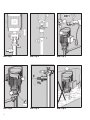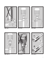
1
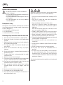
DE Originalbetriebsanleitung 3–12 Exzenterschnecken-fassPumpen GB Operating Instructions 13–20 eccentric screw drum Pumps Typ/Type B70V-HD-D B70V-HD-SR Vor Inbetriebnahme Betriebsanleitung lesen! Read this operating instructions before start up! Für künftige Verwendung aufbewahren. To be retained for future reference. Bild / Fig. 1 Bild / Fig. 2 Bild / Fig. 3 Bild / Fig. 4 Bild / Fig. 5 Bild / Fig. 6 Bild / Fig. 7 Bild / Fig. 8 Bild / Fig. 9 Bild / Fig. 10 Bild / Fig. 11 Bild / Fig. 12 DE DE Inhaltsverzeichnis 1. Allgemeines............................................................................................................7 1.1 Lieferumfang..................................................................................................7 1.2 Baujahr..........................................................................................................7 2. Motorvarianten........................................................................................................7 2.1 Drehstromantrieb für Typ B70V-HD...................................................................7 2.2 Druckluftantrieb für Typ B70V-HD....................................................................7 2.3 Antrieb für Typ B70V-HD-SR...........................................................................7 3. Bestimmungsgemäße Verwendung...........................................................................7 3.1 Einsatz im explosionsgefährdeten Bereich oder Fördern brennbarer Flüssigkeiten.............................................................7 3.2 Beständigkeit...................................................................................................8 3.3 Einsatztemperatur............................................................................................8 4. Inbetriebnahme.......................................................................................................8 4.1 Montage B70V-HD.........................................................................................8 4.2 Montage B70V-HD-SR....................................................................................8 4.3 Elektrischer Anschluss von Drehstrommotoren.................................................8 4.4 Drehrichtung..................................................................................................8 4.5 Mechanische Belastung des Pumpwerks.........................................................8 4.6 Maximale Eintauchtiefe...................................................................................8 5. Bedienung..............................................................................................................9 5.1 Trockenlauf....................................................................................................9 5.2 Saugtrichter...................................................................................................9 5.3 Betrieb bei geschlossenem Auslass.................................................................9 5.4 Betrieb mit Zirkulationsleitung.........................................................................9 6. Wartung.................................................................................................................9 6.1 Reinigung......................................................................................................9 6.2 Schmierung.................................................................................................10 6.3 Statorwechsel..............................................................................................10 7. Reparaturen..........................................................................................................10 8. Besondere Bedingungen zum Explosionsschutz.......................................................11 8.1 Potentialausgleich und Erdung......................................................................11 8.2 Leitfähige Schläuche/Schlaucheinbindungen..................................................11 8.3 Erläuterung der Zoneneinteilung bei der Anwendung von Exzenterschneckenpumpen für brennbare Flüssigkeiten...........................12 8.4 Rückverfolgbarkeit........................................................................................12 Konformitätserklärung...............................................................................................23 DE Allgemeine Sicherheitshinweise Die Betriebsanleitung ist: •als Bestandteil des Produkts zu betrachten. •vor Inbetriebnahme vom Bediener zu lesen und während des Betriebs einzuhalten. •an jeden nachfolgenden Besitzer oder Benutzer des Produkts weiterzugeben. •um jede zusätzlich erhaltene Ergänzung durch den Benutzer zu erweitern. Grundsätze zur Sicherheit Das Gerät ist nach dem Stand der Technik und den anerkannten sicherheitstechnischen Regeln gebaut. Dennoch können bei der Verwendung Gefahren entstehen wenn es: • von nicht geschultem oder nicht eingewiesenem Personal bedient wird, • nicht bestimmungsgemäß eingesetzt wird, ·•unsachgemäß instand gehalten oder gewartet wird. Folgende Sicherheitshinweise sind zu beachten: 1. Die bestimmungsgerechte Gebrauchslage der Pumpe ist senkrecht. 2. Prüfen Sie die Beständigkeit der Pumpe gegen das Fördermedium. 3. Beachten Sie die Grenzwerte für Temperatur, Viskosität und Dichte der Förderflüssigkeit. 4. Drehrichtung muss mit Pfeilrichtung übereinstimmen (B70V). 5. Beachten Sie, dass alle Anschlüsse und Verbindungen richtig befestigt sind. 6. Prüfen Sie ob der Motor ausgeschaltet ist, bevor Sie die elektrische Verbindung herstellen. 7. Der Antriebsmotor muss sich außerhalb des ortsbeweglichen Gefäßes bzw. Behälters befinden. 8. Beachten Sie die maximale Eintauchtiefe. 9. Betreiben Sie die Pumpe bei geschlossenem Auslass nicht ohne Bypassventil mit Rückströmleitung. 10.Die Pumpe darf nicht trockenlaufen. Schalten Sie die Pumpe bei leerem Behälter ab. 11.Tragen Sie beim Fördern gefährlicher Flüssigkeiten passende Schutzkleidung: Gesichtsmaske oder Schutzbrille, Schürze und Handschuhe. 12.Fassen Sie nicht in die Ansaugöffnung der Pumpe. 13.Kontrollieren Sie die Leckageöffnung auf auslaufende Flüssigkeit. 14.Instandsetzung nur durch den Hersteller oder autorisierte Vertragswerkstätten. Beim Einsatz in explosionsgefährdeter Umgebung, oder beim Fördern brennbarer Flüssigkeiten ist zusätzlich zu beachten: 1. Verwenden Sie nur Pumpwerke mit Kennzeichnung nach ATEX-Richtlinie. 2. Verwenden Sie für brennbare Flüssigkeiten nur mit PTB-Nr. gekennzeichnete PTFE-Statoren und Statorhülsen. 3. Setzen Sie nur folgende explosionsgeschützte Antriebsmotoren ein: B70V-HD-D: Drehstrom- und Druckluftmotoren mit einer Leistung bis zu 1 kW und einer maximalen Drehzahl von 900 1/min. B70V-HD-SR: Universalmotoren mit einer Leistung bis zu 1 kW und einer maximalen Drehzahl von 14400 1/min. 4. Sehen Sie eine Motorschutzeinrichtung und einen EinAusschalter vor, um einen automatischen Anlauf durch Einschalten der Pumpe mittels Stecker auszuschließen. 5. Der elektrischer Anschluss im explosionsgefährdeten Bereich darf nur mit explosionsgeschütztem Stecker oder explosionsgeschütztem Klemmenkasten erfolgen. 6. Stellen Sie vor Pumpbeginn den Potentialausgleich zwischen Pumpwerk und Behältnis her. 7. Verwenden Sie leitfähige Druckschläuche und leitfähige Schlaucheinbindungen. 8. Pumpen Sie keine Flüssigkeiten mit geringer Leitfähigkeit, da sich diese elektrostatisch aufladen können. 9. Setzen Sie die Fasspumpe nicht ortsfest ein. 10.Überwachen Sie den Betrieb der Pumpe während des Pumpvorganges. 11.Instandsetzung nur durch den Hersteller oder autorisierte Vertragswerkstätten und nur mit Originalersatzteilen. Die Einstellwerte der Gleitringdichtung sind zwingend einzuhalten, da es ansonsten zu unzulässigen Erwärmungen kommen kann. Halten Sie die Unfallverhütungsvorschriften des jeweiligen Landes unbedingt ein. DE 1. Allgemeines 2.3 Antrieb für Typ B70V-HD-SR Eine Lutz Exzenterschnecken-Fasspumpe der Baureihe B70VHD besteht aus einem Universal-, Drehstrom- oder Druckluftmotor und einem Pumpwerk. Fördermenge und Förderhöhe sind durch verschiedene Baugrößen wählbar. Dadurch kann die Pumpe für den jeweiligen Einsatzfall passend ausgesucht werden. Es stehen Universalmotoren und Druckluftmotoren zur Wahl: - Universalmotor MA II und MI 4 - Universalmotor ME II - explosionsgeschützt - Druckluftmotoren MD-1, 2 und 3 1.1 Lieferumfang Motor und Pumpwerk der Baureihe B70V-HD werden, wenn keine besonderen Kundenwünsche vorliegen, in zwei separaten Kartons ausgeliefert. Die Verpackung kann ebenfalls bestellte Zubehörteile enthalten. Prüfen Sie deshalb die Lieferung mit Hilfe der Bestellung auf Vollständigkeit. 1.2 Baujahr Das Baujahr des Gerätes ist aus dem Feld für die Seriennummer ersichtlich. Dort sind mit einem Bindestrich die letzten beiden Stellen des Baujahrs an die Seriennummer angehängt (z.B. -10 für das Jahr 2010). 2. Motorvarianten Die Lutz Exzenterschnecken-Fasspumpe der Baureihe B70V-HD ist in drei Varianten erhältlich. 2.1 Drehstromantrieb für Typ B70V-HD Die Pumpen der Baureihe B70V-HD werden von Drehstrommotoren angetrieben. Folgende Drehstrommotoren stehen zur Auswahl: 0,37, 0,55, 0,75 und 1,1 kW, 700 oder 900 1/min. 230/400 V, 50 Hz, Schutzart IP 54. Andere Schutzarten, Spannungen und Leistungen und Drehzahlen auf Anfrage. Weitere Informationen entnehmen Sie bitte der Anleitung des Drehstrommotors. Weitere Informationen entnehmen Sie bitte der jeweiligen Betriebsanleitung. 3. Bestimmungsgemäße Verwendung Die Exzenterschneckenpumpe der Baureihe B70V-HD ist in unterschiedlichen Baugrößen lieferbar. Sie dient zum Fördern von viskosen, klebenden, auskristallisierenden, verschmutzten oder aushärtenden Flüssigkeiten wie z.B. Farben und Lacke aus ortsbeweglichen Gefäßen. Die Pumpwerke sind nur für den senkrechten Einsatz bestimmt. Das Gerät ist nur für den Einsatz im gewerblichen Bereich vorgesehen. Jeder darüber hinausgehende Gebrauch sowie Veränderungen an dem Produkt gelten als nicht bestimmungsgemäß. Für hieraus resultierende Schäden haftet der Hersteller nicht, das Risiko hierfür trägt allein der Betreiber. 3.1 Einsatz im explosionsgefährdeten Bereich oder Fördern brennbarer Flüssigkeiten Die Exzenterschneckenpumpen der Baureihe B70V-HD sind gemäß II 1/2 G c IIB T4 nach ATEX zugelassen. Innerhalb der Behälter bzw. der Pumpe gelten die Anforderungen der Kategorie 1. Alle angebauten Teile, wie Kupplung, Getriebe und Antriebsmotor gelten die Anforderungen der Kategorie 2. 2.2 Druckluftantrieb für Typ B70V-HD Druckluftmotoren Typ 4 DA, 6 DA oder 8 DA mit den Leistungen 0,45, 1,0, 1,7 kW bei 6 bar und 900 1/min. Betriebsdruck max. 7 bar, empfohlene Drehzahl 200-900 1/min., Luftverbrauch 55, 80 bzw. 130 Nm³/h, Luftanschlussgewinde 1/4“ NPT bzw. 1/2“ NPT. Weitere Informationen entnehmen Sie bitte der Anleitung des Druckluftmotors. DE 3.2 Beständigkeit Prüfen Sie anhand einer Beständigkeitstabelle (z.B. Lutz-Beständigkeitstabelle) und der nachfolgenden Werkstoffauflistung, ob das Pumpwerk für die Förderflüssigkeit geeignet ist: Teil Tauchrohr, Rotor, Gelenkwelle und Pumpenfuß Gelenkdichtung Gleitringdichtung Stator Pumpenwerkstoff Edelstahl Niro 1.4571 Vitonh Hartmetall / Hartmetall / Vitonh alternativ: Hartmetall / Hartmetall / EPDM PTFE Vitonh ist ein eingetragenes Warenzeichen von Du Pont Performance Elastomers. Achten Sie beim Reinigen der Pumpe darauf, dass alle benetzten Teile gegen das Reinigungsmittel beständig sind! 3.3 Einsatztemperatur Förderflüssigkeit max. Umgebungstemperatur 100°C -20°C bis +40°C 4. Inbetriebnahme 4.1 Montage B70V-HD Schrauben Sie den Pumpenmotor mit passendem Kupplungsstück auf die Laterne des Pumpwerks auf (Bild 1). Stellen Sie bei nicht vormontiertem Kupplungsteil auf der Motorwelle das vollständige Eingreifen der beiden Kupplungsteile (MotorPumpe) sicher. Anschließend befestigen Sie den Motor mit 4 Schrauben. 4.2 Montage B70V-HD-SR Setzen Sie den Pumpenmotor auf das Pumpwerk (Bild 2). Drehen Sie dabei den Motor leicht, dass der Mitnehmer richtig in die Kupplung eingreift. Verbinden Sie nun mit dem Handrad (Rechtsgewinde) den Motor und das Pumpwerk fest miteinander. Achten Sie auf richtigen und festen Sitz! 4.3 Elektrischer Anschluss von Drehstrommotoren Der elektrische Anschluss darf nur durch geschultes Fachpersonal erfolgen. Dabei sind folgende Bedingungen einzuhalten: - Nehmen Sie alle Arbeiten im spannungslosen Zustand des Motors vor. Bringen Sie den Schutzschalter in Aus-Stellung. - Netzspannung und Frequenz müssen mit den Angaben auf dem Typenschild übereinstimmen (Bild 3). - Die Abmessung des Anschlusskabels muss dem Nennstrom angepasst sein. - Die Isolierung des Anschlusskabels muss den Umgebungsbedingungen angepasst sein. 4.4 Drehrichtung Die Drehrichtung des Motors muss mit dem Drehrichtungspfeil auf dem Zwischenstück übereinstimmen (Bild 4). Klemmen Sie den Motor ggf. um. 4.5 Mechanische Belastung des Pumpwerks Ein Verbiegen des Pumpwerks durch mechanische Belastung schränkt die Funktion und die Lebensdauer ein. Vermeiden Sie deshalb Druck und Zugkräfte am Auslaufstück. Begrenzen Sie das Biegemoment MB auf 50 Nm (Bild 5). 4.6 Maximale Eintauchtiefe Stellen Sie sicher, dass die Pumpe nicht tiefer als bis zum Auslaufstutzen eintaucht (Bild 6). DE 5. Bedienung 6. Wartung 5.1 Trockenlauf 6.1 Reinigung Man spricht von Trockenlauf, wenn die Pumpe absolut keine Flüssigkeit fördert (Bild 7). Trockenlauf muss ausgeschlossen werden. Stellen Sie dies durch Beaufsichtigung oder technische Hilfsmittel wie z.B. Strömungswächter sicher. Nach dem Fördern von aggressiven, klebenden, auskristallisierenden oder verschmutzten Flüssigkeiten ist die Pumpe besonders vor längeren Stillstandzeiten zu entleeren, zu spülen und gegebenenfalls zu reinigen. Dabei ist die Funktion der Gleitringdichtung und der Gelenklabdichtungen zu kontrollieren. 5.2 Saugtrichter Um beim Fördern das Eintreten von Luft zu verhindern, muss mindestens der Ansaugstutzen vom Fördermedium vollständig bedeckt sein. Beachten Sie bei hochviskosen Produkten außerdem, dass die Bildung von Saugtrichtern verhindert wird. 5.3 Betrieb bei geschlossenem Auslass Die Exzenterschneckenpumpe B70V-HD ist eine positive Verdrängerpumpe. Sie darf nicht gegen geschlossene Absperrorgane wie Zapfpistole, Ventil usw. betrieben werden. Der zu große Druckaufbau kann zu Schäden führen. Beachten Sie, dass folgender Maximaldruck nicht überschritten werden darf: Pumpwerk Maximaldruck B70V-HD 12.1 B70V-HD 25.1 B70V-HD 25.2 B70V-HD 50.1 6 bar 8 bar 10 bar 8 bar 5.4 Betrieb mit Zirkulationsleitung Um das Aushärten an der Gleitringdichtung zu verhindern empfiehlt es sich, die Förderflüssigkeit in Zirkulation zu halten. Entfernen Sie hierzu die Verschlussschraube und schließen Sie eine Zirkulationsleitung mit Absperrhahn am Zirkulationsanschluss (Bild 8) an. Stellen Sie über den Absperrhahn den erforderlichen Zirkulationsstrom ein. Gehen Sie dazu folgendermaßen vor: • Verschließen Sie den Pumpenauslass und die Zirkulationsleitung mit einem Kugelhahn oder einem Ventil. • Beim Pumpentyp B70V-HD können Sie die Pumpe durch Umkehr der Drehrichtung entleeren. • Stellen Sie die Pumpe in einen Behälter mit Reinigungsflüssigkeit. • Öffnen Sie die Zirkulationsleitung. • Schalten Sie die Pumpe in der zum Förderbetrieb notwendigen Drehrichtung ein und lassen Sie Reinigungsflüssigkeit zirkulieren (Bild 9). Diese Maßnahmen sind ausreichend, um die Funktion der Pumpe aufrecht zu erhalten. Wenn sie in einem anderen Fordermedium eingesetzt werden soll, empfehlen wir die Pumpe wie nachfolgend beschrieben zu öffnen und zu reinigen:. • Lösen Sie die Überwurfmutter über dem Pumpenauslass (Bild 10 – Pos. 1). • Ziehen Sie das Pumpenrohr nach unten ab, bis die Gleitringdichtung (Bild 10 – Pos. 2) zugänglich ist. • Sind noch Rückstände der Förderflüssigkeit sichtbar, dann können Sie diese nun entfernen. • Prüfen Sie die Gleitringdichtung (Bild 10 – Pos.2) und die Gelenkabdichtungen (Bild 10 – Pos.3) auf Beschädigungen (z.B. abgebrochene Teile, Risse oder Riefen) und Dichtheit. • Für den weiteren Einsatz können Sie die Pumpe nun wieder zusammenbauen. DE 6.2 Schmierung 7. Reparaturen Die Lutz-Exzenterschneckenpumpe hat keine in kurzen Abständen zu schmierenden Stellen. Die angeflanschten Antriebsaggregate sind wie folgt zu warten: Wenn unterhalb des Pumpenmotors Leckflüssigkeit austritt (Bild 11), dann müssen Sie die Pumpe umgehend abschalten und instand setzen. B70V-HD-D Ersetzen Sie alle 8000 Betriebsstunden oder nach 2 Jahren Betriebszeit die Wälzlager des Motors und der Pumpe. Sie dürfen Reparaturen nur vom Hersteller oder autorisierten Vertragswerkstätten ausführen lassen. Es dürfen nur OriginalErsatzteile von Lutz Pumpen verwendet werden. B70V-HD-SR Planetengetriebe Siehe Betriebsanleitung des Getriebes. Universalmotoren Siehe Betriebsanleitung des Motors. Druckluftmotoren Siehe Betriebsanleitung des Motors Vor der Rücksendung des Gerätes müssen Sie folgendes beachten: •Rückstände im Gerät können die Umwelt und die menschliche Gesundheit gefährden. Entleeren Sie das Gerät vollständig, spülen und reinigen Sie es danach. •Teilen Sie uns mit, welche Flüssigkeit gefördert wurde. Fügen Sie der Lieferung ein entsprechendes Sicherheitsdatenblatt bei. 6.3 Statorwechsel Für brennbare Flüssigkeiten nur mit PTB-Nr. gekennzeichnete PTFE-Statoren und Statorhülsen verwenden. Stator und Rotor sind Verschleißteile. Ihre Lebensdauer ist stark von den Einsatzbedingungen abhängig. • Entleeren Sie vor dem Zerlegen die Restflüssigkeit im Pumpwerk über das Auslaufstück. • Zur Demontage lösen Sie die Klemmschraube an der Statorhülse. • Schrauben Sie den Pumpenfuß los und ziehen Sie ihn mit Kraft ab. • Drücken Sie den Stator aus dem Pumpenfuß (Statorhülse) heraus. • Säubern Sie verschmutzte Gewinde am Pumpenrohr und Statorhülse und fetten Sie diese leicht ein. • Legen Sie zur Montage den ersten Druckring in die Statorhülse ein • Drücken Sie den neuen Stator in die Statorhülse ein. • Legen Sie den zweiten Druckring auf den Stator. Beachten Sie bei Feststoffstatoren die Nase und die Kerbe an der Hülse und dem Stator. • Schrauben Sie die Statorhülse auf das Pumpenrohr. • Ziehen Sie die Statorhülse handfest an und klemmen Sie diese mit der Klemmschraube. 10 DE 8. Besondere Bedingungen zum Explosionsschutz 8.1 Potentialausgleich und Erdung Stellen Sie vor Inbetriebnahme der Pumpe unbedingt den Potentialausgleich im System Pumpe - zu entleerendes Behältnis - zu befüllendes Behältnis - her. Gleiches Potential zwischen Pumpe und zu entleerendem Behältnis erreichen Sie durch Anklemmen des Potentialausgleichskabels (Bestell-Nr. 0204-994). Entfernen Sie zur besseren Leitfähigkeit Farbe und Schmutz an den Klemmstellen. Eine leitfähige Verbindung zwischen zu entleerendem und zu füllendem Behältnis wird durch einen leitfähigen Untergrund (z.B. leitfähige Roste) sichergestellt. Dann muss ein gut leitfähiger Übergang zwischen Behältnis und Untergrund vorhanden sein. 8.2 Leitfähige Schläuche/Schlaucheinbindungen In jedem Fall muss der an dem Druckstutzen der Fasspumpe angeschlossene Schlauch - hinsichtlich elektrostatischer Aufladungen - ausreichend elektrisch leitfähig sein. Der ohmsche Widerstand zwischen den Armaturen – in diesem Fall zwischen Pumpwerk und Zapfpistole - darf je nach Schlauchtype einen Grenzwert nicht überschreiten. 1.Kennzeichnung des Schlauches mit dem Symbol „M“ Grenzwert ≤ 102 W (Bild 12 - À) 2.Kennzeichnung des Schlauches mit dem Symbol „W“ Grenzwert ≤ 106 W (Bild 12 - ) Die Schlaucheinbindung muss einen gut leitfähigen Übergang zwischen Schlauch und Pumpwerk sowie Schlauch und Zapfpistole sicherstellen. Ist dies ausnahmsweise nicht der Fall, so ist die separate Erdung aller leitfähigen Teile (z.B. metallenes Mundstück am Schlauchende) unbedingt erforderlich. Das Einbinden von leitfähigen Schläuchen mit Armaturen zu Schlauchleitungen verlangt die Kennzeichnung und Prüfung nach DIN EN 12 115. Erklärung: (1) Potentialausgleichskabel, (2a) leitfähiger Untergrund oder Anschluss eines Potentialausgleichskabels an beiden Fässern, (2b) galvanische Verbindung (geringer Übergangswiderstand zur Erde), (3) leitfähiger Schlauch, (4) leitfähige Verbindung von Schlauch und Schlauchstecker, (5) Pumpwerk Kategorie 1/2, (6) Explosionsgeschützter Motor 11 DE 8.3 Erläuterung der Zoneneinteilung bei der Anwendung von Exzenterschneckenpumpen für brennbare Flüssigkeiten - Im Inneren eines Fasses oder Behältnisses herrscht generell Zone 0. - Die Trennstelle zwischen Zone 0 und Zone 1 wird durch das Fass-Spundloch bzw. die Oberkante des Behältnisses festgelegt. - Räume, in denen um- oder abgefüllt wird fallen grundsätzlich unter Zone 1. - Für Fass- und Behälterpumpen folgt daraus: 1. Verwenden Sie zum Fördern brennbarer Flüssigkeiten nur Pumpwerke der Gerätegruppe II, Kategorie 1/2 G. Diese erfüllen die Vorschriften für den Einsatz in Zone 0. 2. Der Einsatz von explosionsgeschützten Motoren, gleich welcher Schutzart, in Zone 0 ist nicht zulässig. Ausnahmen können nur die örtlichen Überwachungsbehörden machen. 3. Lutz-Motoren der Baureihe ME in der Ausführung „Druckfeste Kapselung - Erhöhte Sicherheit“ erfüllen die Vorschriften für die Gerätegruppe II, Kategorie 2 G. Sie dürfen in Zone 1 eingesetzt werden. 12 8.4 Rückverfolgbarkeit Geräte der Firma Lutz Pumpen für explosionsgefährdete Bereiche sind an Hand einer individuellen Seriennummer gekennzeichnet, die der Rückverfolgbarkeit dient. Aus dieser Zahl können Baujahr und Geräteausführung bestimmt werden. Bei diesem Produkt handelt es sich um ein Gerät für explosionsgefährdete Bereiche. Diesbezüglich und unter Berücksichtigung der ATEX-Richtlinie 94/9/EG sind spezifische Vorkehrungen zu treffen, um die Rückverfolgbarkeit des Gerätes im vor- und nachgeschalteten Bereich sicherzustellen. Unser mit ATEX-Bescheid zertifiziertes QM-System gewährleistet diese Rückverfolgbarkeit bis zum Ort der ersten Auslieferung. Ausgenommen im Falle gegenteilig lautender vertraglicher Bestimmungen sind alle Personen, die diese Geräte weiterliefern, dazu verpflichtet, ein System einzuführen, das eine eventuell erforderliche Rückrufaktion für fehlerhafte Geräte ermöglicht. GB Table of Contents 1. General................................................................................................................14 1.1 Scope of supply............................................................................................14 1.2 Year of construction......................................................................................14 2. Motor types..........................................................................................................14 2.1 Three-phase drive for type B70V-HD...............................................................14 2.2 Compressed air drive for type B70V-HD.........................................................14 2.3 Drive for type B70V-HD-SR...........................................................................14 3. Proper use............................................................................................................14 3.1 Operation in hazardous location or pumping flammable liquids.......................................................................14 3.2 Resistance....................................................................................................15 3.3 Operating temperature...................................................................................15 4. Starting up............................................................................................................15 4.1 Installation of the B70V-HD...........................................................................15 4.2 Installation of the B70V-HD-SR......................................................................15 4.3 Electrical connection of three-phase motors...................................................15 4.4 Direction of rotation......................................................................................15 4.5 Mechanical loads on the pump tube..............................................................15 4.6 Maximum immersion depth...........................................................................15 5. Operation.............................................................................................................16 5.1 Dry running..................................................................................................16 5.2 Suction funnel..............................................................................................16 5.3 Operation with closed discharge....................................................................16 5.4 Operation with circulation line.......................................................................16 6. Maintenance . ......................................................................................................16 6.1 Cleaning......................................................................................................16 6.2 Lubrication...................................................................................................17 6.3 Changing the stator......................................................................................17 7. Repairs.................................................................................................................17 8. Special regulations for the explosion protection.......................................................18 8.1 Equipotential bonding and earthing................................................................18 8.2 Conductive hoses / hose connections............................................................18 8.3 Explanation of the zone classification when using eccentric screw pumps for flammable liquids.................................................19 8.4 Traceability...................................................................................................19 Declaration of Conformity..........................................................................................23 13 GB General safety information The operating instruction has to be considered as: •part of the product. •must be read by the operator before starting and must be followed during operation. •must be handed over to any following owners or users of the product. •must be completed by the user for any additional received addendum. Principles of safety The apparatus is constructed in conformity with the state of the art and approved safety-related standards. Danger however can occur during use if: • it is operated by unskilled personnel • it is used improperly • maintenance or service is incorrectly. Following safety information must be observed: 1. The pump may only be operated in an upright position. 2. Ensure that the pump is resistant to the medium being pumped. 3. Note the limit values for temperature, viscosity and density of the medium being pumped. 4. The motor must rotate in the direction indicated by the arrow (B70V). 5. Ensure that all connections and fittings are properly tightened. 6. Ensure that the motor is switched off before connecting to the electricity supply. 7. The drive motor must be located outside the mobile container or drum. 8. Note the maximum immersion depth. 9. The pump may only be operated with the discharge closed if a bypass valve with return line has been installed. 10.The pump must not be allowed to run dry. Pump must be switched off when the container is empty. 11.Wear appropriate protective clothing when handling hazardous liquids. Face mask or goggles, apron and gloves. 12.Do not reach into the intake port of the pump. 13.The leakage port must be checked for leaks. 14.The pump may only be repaired by the manufacturer or a duly authorized repair shop. 14 Application in explosion hazard areas or pumping flammable liquids the following points must be noted additionally: 1. Only use pump tubes with identification according to ATEX directive. 2. Only use PTFE stators and stator sleeves marked with PTB-No. for flammable liquids. 3. Only use following explosion proof drive motors: B70V-HD-D: Three-phase motors and compressed air motors with a power of up to 1 kW and a max. speed of 900 1/min. B70V-HD-SR: Universal motors with a power of up to 1 kW and a max. speed of 14400 1/min. 4. Provide a motor protection and an on/off switch against automatically starting the pump when inserting the plug. 5. Electric connection in explosion hazard areas only with explosion proof plug or explosion proof terminal box. 6. Connect the equipotential bonding between pump tube and container before starting operation. 7. Use conductive pressure hoses and conductive hose connections. 8. Do not pump low conductive liquids. Electrostatic danger may occur. 9. Do not use the drum pump for stationary operation. 10.The pump must not be left unattended while in operation. 11.The pump may only be repaired by the manufacturer or a duly authorized repair shop. Only use genuine Lutz replacement parts. The setting values of the mechanical seal must be observed without fail. Otherwise inadmissible warming up will occur. The national accident prevention regulations must be observed without fail. GB 1. General 2.3 Drive for type B70V-HD-SR Each Lutz eccentric screw drum pump of series B70V-HD comprises an universal-, a 3-phase- or a compressed air motor and a pump tube. The flow rate and delivery head depend on the selected pump size. This means that the most appropriate pump can be chosen for each individual application. The following universal motors and compressed air motors are available for this type: - Universal motor MA II and MI 4 - Universal motor ME II - explosion proof - Compressed air motors MD-1, 2 and 3 1.1 Scope of supply Further information can be found in the respective operating instructions. The motor and pump tube of series B70V-HD are packed in two separate cartons unless specified otherwise by the customer. The packaging may also contain any accessories ordered. It is therefore important to check that the consignment is complete as ordered. 3. Proper use 1.2 Year of construction The year of construction of the appliance can be seen on the field for the serial number. Here are attached to the serial number the both last digits of the year of construction, e.g. (-10 for the year 2010). 2. Motor types The Lutz eccentric screw drum pump of series B70V-HD is available in three different versions. 2.1 Three-phase drive for type B70V-HD The pumps of series B70V-HD are driven by three-phase motors. The following three-phase motors are available: 0.37, 0.55, 0.75 and 1.1 kW, 700 or 900 1/min., 230/400 V, 50 Hz, type of protection IP 54. Other types of protection, voltages, motor ratings and speeds are available on request. Further information can be found in the operating instructions for three-phase motors. The eccentric screw pump of series B70V-HD is available in different sizes. The pump is used for pumping viscous, adhesive, crystallizing, dirty or hardening fluids, e.g. paints and lacquers, from mobile vessels. The pump tubes may only be installed in an upright position. The apparatus is provided for commercial use only. Any other use as well as any modifications of the product have to be considered as improper use. The manufacturer will not be held responsable for any damages resulting from such improper use, the risk lies solely with the user. 3.1 Operation in hazardous location or pumping flammable liquids The eccentric screw pumps of series B70V-HD are ATEXapproved according to II 1/2 G c IIB T4. Inside of the container and the pump, requirements of category 1 are valid. For all attached parts, e.g. coupling, gear and drive motor, requirements of category 2 are valid. 2.2 Compressed air drive for type B70V-HD Compressed air motors of type 4 DA, 6 DA or 8 DA rated at 0.45, 1.0 or 1.7 kW for 6 bar and 900 1/min. Operating pressure max. 7 bar, recommended speed 200-900 1/min., air consumption 55, 80 or 130 Nm³/h, air connection thread 1/4" NPT or 1/2" NPT. Further information can be found in the operating instructions for compressed air motors. 15 GB 3.2 Resistance 4.3 Electrical connection of three-phase motors The compatibility of the pump tube for the medium in question must be checked with the aid of a resistance table (e.g. Lutz resistance table) and the table of materials. Part Immersion tube, rotor, universal joint shaft and pump foot Joint gasket Mechanical seal Stator Pump material - stainless steel SS 1.4571 Vitonh Hard metal / Hard metal / Vitonh alternatively: Hard metal / Hard metal / EPDM PTFE The electrical connection may only be carried out by trained qualified personnel. Following regulations must be observed: - All works must only be carried out in voltage-free condition of the motor. Protection switch must be set to OFF-position. - Mains voltage and frequency are as specified on the rating plate (Fig. 3). - Dimension of the connecting cable must be adjusted to the nominal current. - The insulation of the connecting cable must be adjusted to the environmental conditions. 4.4 Direction of rotation Vitonh is a registered trademark of Du Pont Performance Elastomers. The motor must rotate in the direction indicated by the arrow on the adapter (Fig. 4). Reconnect the motor as necessary. When cleaning the pump, ensure that all parts in contact with the cleaning agent are also compatible with it! 4.5 Mechanical loads on the pump tube 3.3 Operating temperature The pump tube’s functioning and service life are impaired when deformed by mechanical loads. For this reason, the outlet must not be subjected to compressive or tensile forces. The bending moment MB at the outlet must not exceed 50 Nm (Fig. 5). Liquid max. Ambient temperature 100°C -20°C up to +40°C 4.6 Maximum immersion depth 4. Starting up 4.1 Installation of the B70V-HD Screw the pump motor and matching coupling piece onto the lantern of the pump tube (Fig. 1). If the coupling part has not been fitted on the motor shaft beforehand, care must be taken to ensure that both coupling parts (motor and pump) engage completely. Afterwards fix the motor with 4 screws. 4.2 Installation of the B70V-HD-SR Attach the pump motor onto the pump tube (Fig. 2). The motor must be turned slightly to ensure that the driver engages correctly in the coupling of the pump tube. Connect the motor and the pump tube with the hand wheel (right-hand thread). Ensure that the pump is fitted correctly and securely. 16 Make sure that the pump is not submerged further than its discharge port (Fig. 6). GB 5. Operation 6. Maintenance 5.1 Dry running 6.1 Cleaning The pump is said to run dry if it continues to operate without pumping any liquid (Fig. 7). Dry running must be avoided. This can be ensured by remaining in attendance or with the aid of such technical means as a flow monitor, etc. The pump must be emptied, flushed and if necessary cleaned after pumping adhesive, crystallizing or contaminated liquids especially before longer downtimes. Function of mechanical seal and joint seals must be controlled. 5.2 Suction funnel Proceed as follows: At least the intake port must be completely covered with medium in order to prevent the infiltration of air while pumping. When pumping highly viscous products, care must also be taken to prevent the formation of suction funnels. • Close the pump discharge and the circulation pipeline by means of a valve. • Position the pump into a container with cleaning agent. 5.3 Operation with closed discharge • Open the circulation line. The eccentric screw pump B70V-HD is a positive displacement pump and must not be operated with closed shutoff elements, such as the nozzle, valves, etc. An excessive pressure build-up may result in damage. Make sure that following max. pressure must not be exceeded: Pump tube Max. pressure • The B70V-HD pump can be emptied by changing the direction of rotation. B70V-HD 12.1 B70V-HD 25.1 B70V-HD 25.2 B70V-HD 50.1 6 bar 8 bar 10 bar 8 bar 5.4 Operation with circulation line It is recommended to keep the liquid being pumped in circulation in order to prevent hardening at the mechanical seal. Remove the locking screw and connect a circulation line with shutoff valve at the circulation connector (Fig. 8). Adjust the requested circulation flow via the shutoff valve. • Start the pump with the direction of rotation necessary for operation and let the cleaning agent circulate (Fig. 9). These steps are sufficient to guarantee operational reliability of the pump. If the pump shall be used for another liquid, we recommend to open and to clean the pump as follows: • Remove the wing nut above the pump discharge (Fig. 10 – Item 1). • Remove the pump tube downwards until the mechanical seal is accessible (Fig. 10 – Item 2). • Any residues of the liquid being pumped now can be removed. • Inspect the mechanical seal (Fig. 10 – Item 2) and the hinge seals (Fig. 10 – Item 3) for damage and leak tightness (e.g. broken parts, cracks or grooves). • The pump now can be reassembled for further use. 17 GB 6.2 Lubrication 7. Repairs No parts of the Lutz eccentric screw pump need be lubricated at short intervals. The flanged-on drive units should be serviced as follows: The pump must be switched off and repaired immediately if liquid leaks out below the pump motor (Fig. 11). B70V-HD-D The rolling bearings of the motor and the pump should be replaced after 8000 hours or 2 years of operation. B70V-HD-SR Planetary gears Refer to the operating instructions for the gear. Universal motors Refer to the operating instructions for the motor. Compressed air motors Refer to the operating instructions for the motor 6.3 Changing the stator Only use PTFE stators and stator sleeves marked with PTB-No. for flammable liquids. Stator and rotor are wear parts. Their service life largely depends on the prevailing conditions. • The residual liquid in the pump tube must be emptied through the outrun piece before disassembly. • Release the clamp screw at the stator sleeve for disassembly. • Release and remove the pump foot. • Force the stator out of the pump foot (stator sleeve). • Soiled threads on the pump tube and the stator sleeve must be cleaned and lightly lubricated. • For assembly insert the first thrust ring into the stator sleeve. • Press the new stator into the stator sleeve. • Put the second thrust ring onto the stator. Note the nose and notch on the sleeve and stator when replacing solid stators. • Screw the stator sleeve onto the pump tube. • Fasten the stator sleeve hand-tight and clamp with the clamp screw. 18 Repairs should only be made by the manufacturer or authorized Lutz-dealers. Only use original Lutz spare parts. Before sending back the appliance, following must be observed: •Residuals in the appliance can cause danger to the environment and human health. The appliance must be completely emptied, rinsed and cleaned. •Please advise which liquid has been pumped. A respective safety data sheet must be attached to the return consignment. GB 8. Special regulations for the explosion protection 8.1 Equipotential bonding and earthing Before starting up the pump, it is essential to establish an equipotential bonding between the pump, the container to be emptied and the container to be filled. The potential between the pump and the container to be emptied is equalized by connecting the equipotential bonding cable (Ref.-No. 0204-994). Paint and dirt should be removed from the connecting points in order to improve the conductivity. The conductive connection between the full and empty containers is achieved by means of a conductive substrate (e.g. conductive gratings). A conductive transition between container and subsurface must be guaranteed. 8.2 Conductive hoses / hose connections Anyway the hose connected to the pressure joint of the drum pump must be sufficiently electrically conductive – with respect to electrostatic charges. The ohmic resistance between the fittings – in this case between the pump tube and the nozzle – may not exceed a limited value depending on the respective hose type. 1.Identification of the hose with the symbol „M“ limited value ≤ 102 W (Fig. 12 - À) 2.Identification of the hose with the symbol „W“ limited value ≤ 106 W (Fig. 12 - ) The hose connection must ensure a highly conductive transition between hose and pump tube, as well as between hose and nozzle. If this is not the case, all conducting parts (such as the metal mouth piece at the end of the hose) shall have to be earthed separately. Connecting of conductive hoses with armatures to the hose lines requires the identification and examination to DIN EN 12 115. Legend: (1) Equipotential bonding cable, (2a) Conductive substrate or connection of an equipotential bonding cable to each of the two drums, (2b) Galvanic connection (low contact resistance towards earth), (3) Conductive hose, (4) Conductive connection between hose and hose connector, (5) Pump tube category 1/2, (6) Explosion proof motor 19 GB 8.3 Explanation of the zone classification when using eccentric screw pumps for flammable liquids - Zone 0 generally prevails inside the drum or container. - The boundary between zone 0 and zone 1 is determined by the bunghole of the drum or the upper edge of the container. - Rooms in which media are transferred from one drum or container to another are always classified as zone 1. - For drum and container pumps this means that: 1. Only pump tubes of unit group II, category 1/2 G may be used to pump flammable liquids. They comply with the regulations for use in zone 0. 2. Regardless of their type of protection, explosion proof motors may not be used in zone 0. Exceptions may only be made by the local supervisory authorities. 3. Lutz motors of series ME of type "explosion proof enclosure - increased-safety" comply with the regulations for unit group II, category 2 G. They are allowed for use in zone 1. 20 8.4 Traceability Products manufactured by Lutz Pumpen for potentially explosive atmospheres are identified by an individual batch number which allows them to be traced. This number provides the year of construction and the design of the equipment. This product is an appliance for potentially explosive atmospheres. In this regard and in compliance with the EC ATEX 94/9 Directive, provisions must be made to ensure ascending and desccending traceability. Our ATEX notified quality system ensures this traceability up to the initial point of delivery. Except as otherwise agreed in writing, anyone that guarantees to redeliver said equipment undertakes to put in place a system that allows for equipment that is not conform to be recalled if necessary. DE GB 21 DE 22 GB Lutz Pumpen GmbH Erlenstraße 5-7 D-97877 Wertheim Lutz Pumpen GmbH Erlenstraße 5-7 D-97877 Wertheim EG-Konformitätserklärung Declaration of Conformity Wir erklären, dass folgendes Produkt den Anforderungen der aufgeführten EG-Richtlinien entspricht. Die Inbetriebnahme dieses Produkts ist so lange untersagt, bis festgestellt wurde, dass auch der Antriebsmotor für die Fasspumpe den Bestimmungen aller relevanten Richtlinien entspricht. Bei Verwendung von Antriebsmotoren der Firma Lutz Pumpen GmbH erfüllt das vollständige Produkt die EG-Maschinenrichtlinie. We declare that the following product complies with the provisions of the EC Directives. The product may not be taken into service until it has been established that the drive motor for the drum pump complies with the provisions of all relevant EC-Directives. The complete product complies with the provisions of the EC Directive on machines when driving motors made by Lutz Pumpen GmbH are used. Bei einer nicht mit uns abgestimmten Änderung am Produkt verliert diese Erklärung ihre Gültigkeit. This declaration ceases to be valid if the product is modified in any way without prior consultation with us. Geräteart: Exzenterschnecken-Fasspumpe Type of device: Eccentric screw drum pump Typen: B70V-HD-D B70V-HD-SR Models: B70V-HD-D B70V-HD-SR EG-Richtlinien: EG-Richtlinie für Geräte und Schutzsysteme zur bestimmungsgemäßen Verwendung in explosionsgefährdeten Bereichen (94/9/EG) EG-Maschinenrichtlinie (2006/42/EG) EC Directives: Equipment and protective systems intended for use in potentially explosive atmospheres (94/9/EC) EC Directive on machinery safety (2006/42/EC) EG-Baumusterprüfbescheinigung: Physikalisch-Technische Bundesanstalt 0102, Bundesallee 100, 38116 Braunschweig, PTB 07 ATEX 5001 X EC-Type examination: Physikalisch-Technische Bundesanstalt 0102, Bundesallee 100, 38116 Braunschweig, PTB 07 ATEX 5001 X Angewandte harmonisierte Normen, insbesondere EN ISO 12100-1 EN 13463-1 EN ISO 12100-2 EN 13463-5 Applicable harmonized standards, in particular: EN ISO 12100-1 EN 13463-1 EN ISO 12100-2 EN 13463-5 EN 809 EN 809 Dokumentationsbevollmächtigter: Herr Volker Fertig, Lutz Pumpen GmbH, Erlenstraße 5-7, D-97877 Wertheim Person authorised to compile the technical file: Mr. Volker Fertig, Lutz Pumpen GmbH, Erlenstraße 5-7, D-97877 Wertheim Wertheim, 03.02.2010 Wertheim, 03.02.2010 Jürgen Lutz, Geschäftsführer Jürgen Lutz, Managing Director 23 Lutz Pumpen GmbH Erlenstraße 5-7 D-97877 Wertheim Tel. (0 93 42) 8 79-0 Fax (0 93 42) 87 94 04 e-mail: [email protected] http://www.lutz-pumpen.de Technische Änderungen vorbehalten. 02/10 Subject to technical changes. Best.-Nr. 0698-140 Printed in Germany / Dru.