1
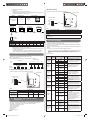
INSTALLATION MANUAL INDOOR UNIT (Wall Mounted Type: EEV internal) English TM INSTALLATIONSANLEITUNG INNENGERÄT (wandmontierter Typ: EEV intern) Deutsch For authorized service personnel only. APPAREIL INTÉRIEUR (Type montage mural : interne EEV) Pour le personnel agréé uniquement. MANUAL DE INSTALACIÓN UNIDAD INTERIOR (Tipo montado en pared: EEV interna) Únicamente para personal de servicio autorizado. MANUALE DI INSTALLAZIONE UNITÀ INTERNA (tipo montato a parete: EEV interno) Español MANUEL D’INSTALLATION Italiano ASYA07GACH/ASHA07GACH ASYA09GACH/ASHA09GACH ASYA12GACH/ASHA12GACH ASYA14GACH/ASHA14GACH Français Nur für autorisiertes Fachpersonal. MANUAL DE INSTALAÇÃO UNIDADE INTERIOR (Tipo mural: modelo interno com EEV) Apenas para técnicos autorizados. РУКОВОДСТВО ПО УСТАНОВКЕ ВНУТРЕННИЙ МОДУЛЬ (настенного типа: внутренний электронный расширительный клапан) Только для авторизованного обслуживающего персонала. MONTAJ KILAVUZU İÇ ÜNİTE (Duvara Monteli Tip: EEV dahili) Português Μόνο για εξουσιοδοτημένο τεχνικό προσωπικό. Русский ΕΣΩΤΕΡΙΚΗ ΜΟΝΑΔΑ (Επιτοίχιος Τύπος: ΗΕΒ εσωτερικά) Türkçe ΕΓΧΕΙΡΙΔΙΟ ΕΓΚΑΤΑΣΤΑΣΗΣ Ελληνικά A uso esclusivo del personale tecnico autorizzato. Yalnızca yetkili servis personeli için. PART NO. 9373370130-02 9373370130-02_IM.indb 1 2013-2-16 11:10:56 INSTALLATION MANUAL CAUTION PART NO. 9373370130-02 VRF system indoor unit (Wall mounted type: EEV internal) This mark indicates procedures which, if improperly performed, might possibly result in personal harm to the user, or damage to property. Read carefully all security information before use or install the air conditioner. CONTENTS Do not attempt to install the air conditioner or a part of the air conditioner by yourself. 1. SAFETY PRECAUTIONS ............................................................................................ 1 This unit must be installed by qualified personnel with a capacity certificate for handling refrigerant fluids. Refer to regulation and laws in use on installation place. 2. ABOUT THE UNIT ....................................................................................................... 1 2.1. Precautions for using the R410A refrigerant ......................................................... 1 2.2. Special tool for R410A .......................................................................................... 1 2.3. Accessories .......................................................................................................... 2 2.4. Optional parts ....................................................................................................... 2 3. PIPE INSTALLATION .................................................................................................. 4 4.1. Selecting the pipe material ................................................................................... 4 4.2. Pipe requirement .................................................................................................. 4 4.3. Flare connection (pipe connection) ...................................................................... 5 5. ELECTRICAL WIRING ................................................................................................ 6 5.1. Electrical requirement ........................................................................................... 6 5.2. Wiring method ...................................................................................................... 6 5.3. Unit wiring ............................................................................................................. 7 Always use a separate power supply line protected by a circuit breaker operating on all wires with a distance between contact of 3mm for this unit. The unit must be correctly earthed (grounded) and the supply line must be equipped with a differential breaker in order to protect the persons. The units are not explosion proof and therefore should not be installed in explosive atmosphere. Never touch electrical components immediately after the power supply has been turned off. Electric shock may occur. After turning off the power, always wait 5 minutes before touching electrical components. This unit contains no user-serviceable parts. Always consult authorized service personnel to repairs. FIELD SETTING .......................................................................................................... 8 6.1. Setting the address ............................................................................................... 8 6.2. Custom code setting ............................................................................................. 9 6.3. Switching the upper limit of cooling temperature .................................................. 9 6.4. Function Setting .................................................................................................... 9 6.5. Connecting the wired remote controller (If necessary) ....................................... 10 6.6. External input and external output (Optional parts) ............................................ 11 6.7. Installing the control unit ..................................................................................... 12 7. FINISHING................................................................................................................. 13 8. TEST RUN ................................................................................................................. 14 8.1. Test run using Outdoor unit (PCB) ...................................................................... 14 8.2. Test run using Remote Controller ....................................................................... 14 9. This unit is part of a set constituting an air conditioner. It must not be installed alone or with non-authorized by the manufacturer. INSTALLATION WORK ............................................................................................... 2 3.1. Selecting an installation location .......................................................................... 2 3.2. Installation dimensions ......................................................................................... 2 3.3. Installing the unit ................................................................................................... 3 4. 6. The installation must be carried out in compliance with regulations in force in the place of installation and the installation instructions of the manufacturer. CHECK LIST.............................................................................................................. 14 10. ERROR CODES ........................................................................................................ 14 When moving, consult authorized service personnel for disconnection and installation of the unit. 2. ABOUT THE UNIT 2.1. Precautions for using the R410A refrigerant 1 WARNING Do not introduce any substance other than the prescribed refrigerant into the refrigeration cycle. If air enters the refrigeration cycle, the pressure in the refrigeration cycle will become abnormally high and cause the piping to rupture. If there is a refrigerant leakage, make sure that it does not exceed the concentration limit. If a refrigerant leakage exceeds the concentration limit, it can lead to accidents such as oxygen starvation. Do not touch refrigerant that has leaked from the refrigerant pipe connections or other area. Touching the refrigerant directly can cause frostbite. 1. SAFETY PRECAUTIONS If a refrigerant leakage occurs during operation, immediately vacate the premises and thoroughly ventilate the area. If the refrigerant comes in contact with a flame, it produces a toxic gas. Be sure to read this Manual thoroughly before installation. The warnings and precautions indicated in this Manual contain important information pertaining to your safety. Be sure to observe them. 2.2. Special tool for R410A Hand this Manual, together with the Operating Manual to the customer. Request the customer to keep them on hand for future use, such as for relocating or repairing the unit. WARNING This mark indicates procedures which, if improperly performed, might lead to the death or serious injury of the user. Request your dealer or a professional installer to install the unit in accordance with this Manual. An improperly installed unit can cause serious accidents such as water leakage, electric shock, or fire. If the unit is installed in disregard of the instructions in the Installation Manual, it will void the manufacturer’s warranty. WARNING To install a unit that uses the R410A refrigerant, use dedicated tools and piping materials that have been manufactured specifically for R410A use. Because the pressure of the R410A refrigerant is approximately 1.6 times higher than the R22, failure to use dedicated piping material or improper installation can cause rupture or injury. Furthermore, it can cause serious accidents such as water leakage, electric shock, or fire. Tool name Do not turn ON the power until all work has been completed. Turning ON the power before the work is completed can cause serious accidents such as electric shock or fire. If refrigerant leaks while work is being carried out, ventilate the area. If the refrigerant comes in contact with a flame, it produces a toxic gas. Installation work must be performed in accordance with national wiring standards by authorized personnel only. Except for EMERGENCY, never turn off main as well as sub breaker of the indoor units during operation. It will cause compressor failure as well as water leakage. First, stop the indoor unit by operating the control unit, converter or external input device and then cut the breaker. Make sure to operate through the control unit, converter or external input device. When the breaker is designed, locate it at a place where the users cannot start and stop in the daily work. Contents of change Gauge manifold Pressure is huge and cannot be measured with a conventional (R22) gauge. To prevent erroneous mixing of other refrigerants, the diameter of each port has been changed. It is recommended to use a gauge manifold with a high pressure display range –0.1 to 5.3 MPa and a low pressure display range –0.1 to 3.8 MPa. Charging hose To increase pressure resistance, the hose material and base size were changed. Vacuum pump A conventional (R22) vacuum pump can be used by installing a vacuum pump adapter. Be sure that the pump oil does not backflow into the system. Use one capable for vacuum suction of –100.7 kPa (5 Torr, –755 mmHg). Gas leakage detector Special gas leakage detector for HFC refrigerant R410A. En-1 9373370130-02_IM.indb Sec1:1 2013-2-16 11:11:05 3. INSTALLATION WORK 2.3. Accessories Correct initial installation location is important because it is difficult to move unit after it is installed. WARNING For installation purposes, be sure to use the parts supplied by the manufacturer or other prescribed parts. The use of non-prescribed parts can cause serious accidents such as the unit to fall, water leakage, electric shock, or fire. 3.1. Selecting an installation location WARNING The following installation parts are furnished. Use them as required. Keep the Installation Manual in a safe place and do not discard any other accessories until the installation work has been completed. Select installation locations that can properly support the weight of the indoor. Install the units securely so that they do not topple or fall. Do not discard any accessories needed for installation until the installation work has been completed. Name and Shape Q’ty Application Operating Manual 1 Installation Manual (This book) 1 For indoor unit installation Wall hook bracket 1 CAUTION Do not install the unit in the following areas: • Area with high salt content, such as at the seaside. It will deteriorate metal parts, causing the parts to fail or the unit to leak water. • Area filled with mineral oil or containing a large amount of splashed oil or steam, such as a kitchen. It will deteriorate plastic parts, causing the parts to fail or the unit to leak water. • Area that generates substances that adversely affect the equipment, such as sulfuric gas, chlorine gas, acid, or alkali. It will cause the copper pipes and brazed joints to corrode, which can cause refrigerant leakage. • Area that can cause combustible gas to leak, contains suspended carbon fibers or flammable dust, or volatile inflammables such as paint thinner or gasoline. If gas leaks and settles around the unit, it can cause a fire. • Area where animals may urinate on the unit or ammonia may be generated. Do not use the unit for special purposes, such as storing food, raising animals, growing plants, or preserving precision devices or art objects. It can degrade the quality of the preserved or stored objects. Do not install where there is the danger of combustible gas leakage. Do not install the unit near a source of heat, steam, or flammable gas. Cable tie For remote controller cable binding 1 Cloth tape For indoor unit installation 1 Tapping screw (M4×25mm) Install the unit where drainage does not cause any trouble. Install the indoor unit, power supply cable, transmission cable, and remote controller cable at least 1 m away from a television or radio receivers. The purpose of this is to prevent TV reception interference or radio noise. (Even if they are installed more than 1 m apart, you could still receive noise under some signal conditions.) If children under 10 years old may approach the unit, take preventive measures so that they cannot reach the unit. For wall hook bracket installation Decide the mounting position with the customer as follows: (1) Install the indoor unit on a place having a sufficient strength so that it withstands against the weight of the indoor unit. 8 (2) The inlet and outlet ports should not be obstructed; the air should be able to blow all over the room. Connecting cable For wired remote controller installation 1 (3) Leave the space required to service the air conditioner. (4) A place from where the air can be distributed evenly throughout the room by the unit. (5) Install the unit where connection to the outdoor unit (or RB unit) is easy. Air cleaning filter 2 For installation, refer to the “CLEANING AND CARE” in the operating manual. (6) Install the unit where the connection pipe can be easily installed. (7) Install the unit where the drain pipe can be easily installed. (8) Install the unit where noise and vibrations are not amplified. (9) Take servicing, etc., into consideration and leave the spaces. Also install the unit where the filter can be removed. Air cleaning filter frame 3.2. Installation dimensions 2 For indoor unit installation Seal A 1 Provide a service space for inspection purposes. Do not place any wiring or illumination in the service space, as they will impede service. 60 mm or over Wall hook bracket 50 mm or over 90 mm or over 2.4. Optional parts Description Part No. Application External output wire B 9379529013 For output port External input wire D 9368779016 For control input port (Apply voltage terminal) External input wire F 9368779023 For control input port (Dry contact terminal) External input wire B 9368778002 For forced thermostat off port (Apply voltage terminal) 9368778019 For forced thermostat off port (Dry contact terminal) External input wire E 1,500 mm or over 1,800 mm or over (Wall cap) Drain hose O.D 15.8 to 16.7 mm I.D 13.8 mm En-2 9373370130-02_IM.indb Sec1:2 2013-2-16 11:11:05 Fig. B 3.3. Installing the unit Wall hook bracket Center mark WARNING Install the air conditioner in a location which can withstand a load of at least 5 times the weight of the main unit and which will not amplify sound or vibration. If the installation location is not strong enough, the indoor unit may fall and cause injuries. Lower Lower If the job is done with the panel frame only, there is a risk that the unit will come loose. Please take care. 80 mm dia. hole 3.3.1. Determining the piping direction The piping can be connected in the 5 directions indicated by 1, 2, 3, 4, and 5 in (Fig. A). When the piping is connected in direction 2 or 5, cut along the piping groove in the side of the front cover with a hacksaw. When connecting the piping in direction 3, cut a notch in the thin wall at the front bottom of the front cover. 5 to 10 mm low 10 mm or over 80 mm dia. hole Fasten with vinyl tape Fig. A (Rear) Wall cap* 5 Left outlet Wall pipe* (Inside) 3.3.4. Forming the drain hose and pipe 1 Rear outlet 2 Right outlet 3 Bottom outlet (Outside) *Field supply Wall 4 Left rear outlet CAUTION In order to align the drain hose and drain cap, be sure to insert securely and vertically. Incline insertion will cause water leakage. 3.3.2. Installing the wall hook bracket CAUTION Install the wall hook bracket level, both horizontally and vertically. When inserting, be sure not to attach any material besides water. If any other material is attached, it will cause deterioration and water leakage. After removing drain hose, be sure not to forget mounting drain cap. Be sure to fix the drain hose with tape to the bottom of piping. (1) Install the wall hook bracket so that it is correctly positioned horizontally and vertically. If the wall hook bracket is tiled, water will drip to the floor. (2) Install the wall hook bracket so that it is strong enough to withstand the weight of an adult. [Rear piping, Right piping, Bottom piping] (1) Install the indoor unit piping in the direction of the wall hole and bind the drain hose and pipe together with vinyl tape. • Fasten the wall hook bracket to the wall with 6 or more screws through the holes near the outer edge of the bracket. • Check that there is no rattle at the wall hook bracket. Wall hook bracket Bind with vinyl tape Right piping Pipe (top) Rear piping Bottom piping Indoor unit drain hose (bottom) Tapping screw (2) Install the piping so that the drain hose is at the bottom. 3.3.3. Cutting the hole in the wall for the connecting piping (3) Wrap the pipes of the indoor unit that are visible from the outside with decorative tape. [For Left rear piping, Left piping] (1) Interchange the drain cap, insulation and the drain hose. WARNING For left outlet piping, cut off the piping outlet cutting groove with a hacksaw. If the wall pipe is not used, the cable interconnecting the indoor and outdoor units may touch metal and cause electric leakage. (1) Cut a 80 mm diameter hole in the wall at the position shown in Fig. B. (2) When cutting the wall hole at the inside of the wall hook bracket, cut the hole within the range of the left and right center marks 40 mm below the wall hook bracket. When cutting the wall hole at the outside of the wall hook bracket, cut the hole at least 10 mm below over. (3) Cut the hole so that the outside end is lower (5 to 10 mm) than the inside end. (4) Always align the center of the wall hole. If misaligned, water leakage will occur. Insulation Indoor unit Drain cap drain hose Remove the drain cap by pulling at the projection at the end of the cap with pliers, etc. And remove the insulation. (2) Align the marks on the wall hook bracket and shape the connection pipe. (5) Cut the wall pipe to match the wall thickness, stick it into the wall cap, fasten the cap with vinyl tape, and stick the pipe through the hole. (The connection pipe is supplied in the installation set.) (Fig. B) Connection pipe (Liquid pipe) (6) For left piping and right piping, cut the hole a little lower so that drain water will flow freely. (Fig. B) Bend (R70) with a pipe bender Align the marks. Connection pipe (Gas pipe) (3) Bend the connection piping at the bend radius of 70 mm or more and install no more than 35 mm from the wall. En-3 9373370130-02_IM.indb Sec1:3 2013-2-16 11:11:06 Installation method of Drain cap Screws (4 position) ● Please put the heat insulation inside all along. ● Use a hexagonal wrench (4mm at opposite side) to insert the drain cap, till the drain cap contacts the tip of drain cock. No gap No gap Push [▲] mark Push Drain Cock Hexagonal wrench Front panel Wall hook bracket 3 The front panel is pulled to the front, raising the upper surface, and a front panel is removed. Insulation Drain cap Front panel [Removal method of drain hose] Remove the screw at the left of drain hose and pull out drain hose. Drain hose Screw (4) Insert the spacer, etc. between the indoor unit and the wall hook bracket and separate the bottom of the indoor unit from the wall. Indoor unit Drain fixture (blue) [Installation method of drain hose] Spacer Vertically insert the drain hose toward the inside, so that the drain fixture (blue) can accurately align with the screw hole around the drain cock. After inserting and before replacing, please reinstall and fix the removed screws. Drain fixture (blue) Screw Screw hole Wall hook bracket Drain hose 4. PIPE INSTALLATION Drain cock Be sure to install around the drain hose connector. As the screw is inside, be sure to use screwdriver treated with magnet. 3.3.5. Installing the indoor unit CAUTION Be more careful that foreign matter (oil, water, etc.) does not enter the piping than with refrigerant R410A models. Also, when storing the piping, securely seal the openings by pinching, taping, etc. While welding the pipes, be sure to blow dry nitrogen gas through them. (1) After passing the indoor piping and drain hose through the wall hole, hang the indoor unit on the hooks at the top and bottom of the wall hook bracket. Connection pipe Top hooks (2 mm dia.) 4.1. Selecting the pipe material CAUTION Do not use existing pipes from another refrigeration system or refrigerant. Wall hook bracket Indoor unit (Fitting) Bottom hooks Use pipes that have clean external and internal sides without any contamination which may cause trouble during use, such as sulfur, oxide, dust, cutting waste, oil, or water. It is necessary to use seamless copper pipes. Material : Phosphor deoxidized seamless copper pipes It is desirable that the amount of residual oil is less than 40 mg/10 m. (2) Remove the intake grille. 1 Open the intake grille. Intake grille Do not use copper pipes that have a collapsed, deformed, or discolored portion (especially on the interior surface). Otherwise, the expansion valve or capillary tube may become blocked with contaminants. 2 2 1 1 Improper pipe selection will degrade performance. As an air conditioner using R410A incurs pressure higher than when using conventional (R22) refrigerant, it is necessary to choose adequate materials. • Thicknesses of copper pipes used with R410A are as shown in the table. • Never use copper pipes thinner than those indicated in the table even if they are 2 Pull down the knob. available on the market. Intake grille Knob 3 Lift the intake grille upward, until the axle at the top of the intake grille is removed. (3) Remove the front panel. 1 The thumb is hung on the lower part as shown in the figure, and it pulls to the front, pushing [▲] mark, and bottom hooks (2 position) is removed from wall hook bracket. 2 The front panel bottom is pulled to the front, and bottom hooks is removed indoor unit. Thicknesses of Annealed Copper Pipes (R410A) Pipe outside diameter [mm (in.)] Thickness [mm] 6.35 (1/4) 0.80 9.52 (3/8) 0.80 12.70 (1/2) 0.80 15.88 (5/8) 1.00 19.05 (3/4) 1.20 4.2. Pipe requirement CAUTION Refer to the installation manual for the outdoor unit for description of allowable pipe length and height difference. Use pipe with water-resistant heat insulation. En-4 9373370130-02_IM.indb Sec1:4 2013-2-16 11:11:06 4.3.3. Pipe connection CAUTION Install heat insulation around both the gas and liquid pipes. Failure to do so may cause water leaks. Use heat insulation with heat resistance above 120 °C. (Reverse cycle model only) In addition, if the humidity level at the installation location of the refrigerant piping is expected to exceed 70 %, install heat insulation around the refrigerant piping. If the expected humidity level is 70 to 80 %, use heat insulation that is 15 mm or thicker and if the expected humidity exceeds 80 %, use heat insulation that is 20 mm or thicker. If heat insulation is used that is not as thick as specified, condensation may form on the surface of the insulation. In addition, use heat insulation with heat conductivity of 0.045 W/(m·K) or less (at 20 °C). CAUTION Be sure to install the pipe against the port on the indoor unit correctly. If the centering is improper, the flare nut cannot tighten smoothly. If the flare nut is forced to turn, the threads will be damaged. Do not remove the flare nut from the indoor unit pipe until immediately before connecting the connection pipe. Hold the torque wrench at its grip, keeping it at a right angle with the pipe, in order to tighten the flare nut correctly. 4.3. Flare connection (pipe connection) When the flare nut is tightened properly by your hand, hold the body side coupling with a separate spanner, then tighten with a torque wrench. WARNING Tighten with 2 wrenches. Tighten the flare nuts with a torque wrench using the specified tightening method. Otherwise, the flare nuts could break after a prolonged period, causing refrigerant to leak and generate hazardous gas if the refrigerant comes into contact with a flame. Holding wrench Torque wrench Flare nut 4.3.1. Flaring Use special flare tool exclusive for R410A. (1) Cut the connection pipe to the necessary length with a pipe cutter. (2) Hold the pipe downward so that cuttings will not enter the pipe and remove any burrs. (3) Insert the flare nut (always use the flare nut attached to the indoor and outdoor units (or RB unit) respectively) onto the pipe and perform the flare processing with a flare tool. Use the special R410A flare tool. Leakage of refrigerant may result if other flare nuts are used. (4) Protect the pipes by pinching them or with tape to prevent dust, dirt, or water from entering the pipes. Check if [L] is flared uniformly and is not cracked or scratched. B Indoor unit pipe (Body side) Connection pipe Flare nut [mm (in.)] Tightening torque [N·m (kgf·cm)] 6.35 (1/4) dia. 16 to 18 (160 to 180) 9.52 (3/8) dia. 32 to 42 (320 to 420) 12.70 (1/2) dia. 49 to 61 (490 to 610) 15.88 (5/8) dia. 63 to 75 (630 to 750) 19.05 (3/4) dia. 90 to 110 (900 to 1,100) Die A Pipe Pipe outside diameter [mm (in.)] Dimension A [mm] Flare tool for R410A, clutch type 0 Dimension B-0.4 [mm] 6.35 (1/4) 9.1 9.52 (3/8) 13.2 12.70 (1/2) 0 to 0.5 16.6 15.88 (5/8) 19.7 19.05 (3/4) 24.0 When using conventional (R22) flare tools to flare R410A pipes, the dimension A should be approximately 0.5 mm more than indicated in the table (for flaring with R410A flare tools) to achieve the specified flaring. Use a thickness gauge to measure the dimension A. It is recommended that a R410A flaring tool is used. Widh across falts Pipe outside diameter [mm (in.)] Width across flats of Flare nut [mm] 6.35 (1/4) 17 9.52 (3/8) 22 12.70 (1/2) 26 15.88 (5/8) 29 19.05 (3/4) 36 4.3.2. Bending pipes If pipes are shaped by hand, be careful not to collapse them. Do not bend the pipes in an angle more than 90°. When pipes are repeatedly bend or stretched, the material will harden, making it difficult to bend or stretch them any more. Do not bend or stretch the pipes more than 3 times. CAUTION To prevent breaking of the pipe, avoid sharp bends. If the pipe is bent repeatedly at the same place, it will break. En-5 9373370130-02_IM.indb Sec1:5 2013-2-16 11:11:06 Refer to the table for the breaker specifications of each installation condition. Perform the power crossover wiring within the range of the same refrigerant system. When the crossover wiring is done, make a connection for indoor units to satisfy conditions A and B below. A. Current breaker requirements 5. ELECTRICAL WIRING WARNING Electrical work must be performed in accordance with this Manual by a person certified under the national or regional regulations. Be sure to use a dedicated circuit for the unit. An insufficient power supply circuit or improperly performed electrical work can cause serious accidents such as electric shock or fire. Before starting work, check that power is not being supplied to the all units. For wiring, use the prescribed type of wires, connect them securely, making sure that there are no external forces of the wires applied to the terminal connections. Improperly connected or secured wires can cause serious accidents such as overheating the terminals, electric shock, or fire. Securely install the electrical box cover on the unit. An improperly installed electrical box cover can cause serious accidents such as electric shock or fire through exposure to dust or water. Install sleeves into any holes made in the walls for wiring. Otherwise, a short circuit could result. Use the included connection cables and power cables or ones specified by the manufacturer. Improper connections, insufficient insulation, or exceeding the allowable current can cause electric shock or fire. Do not modify the power cables, use extension cables, or use any branches in the wiring. Improper connections, insufficient insulation, or exceeding the allowable current can cause electric shock or fire. Match the terminal block numbers and connection cable colors with those of the outdoor unit (or RB unit). Erroneous wiring may cause burning of the electric parts. Model MCA AS A07GACH 0.21 A AS A09GACH 0.22 A AS A12GACH 0.24 A AS A14GACH 0.36 A Install an earth leakage breaker. In addition, install the earth leakage breaker so that the entire AC main power supply is cut off at the same time. Otherwise, electric shock or fire could result. Always connect the earth (ground) cable. Improper earthing (grounding) work can cause electric shocks. Install the remote controller cables so as not to be direct touched with your hand. Perform wiring work in accordance with standards so that the air conditioner can be operated safely and positively. Connect the connection cable firmly to the terminal board. Imperfect installation may cause a fire. If the supply cable is damaged, it must be replaced by the manufacturer, its service agent or similarly qualified persons in order to avoid a hazard. 20 A MCA: Minimum Circuit Ampacity MFA: Maximum Fuse Ampacity When the power crossover wiring is done, make it so that the total of the MCA of the connected RB units and indoor units does not exceed the 15 A. For RB unit MCA, refer to the RB unit installation manual. If the capacity of connected RB units and indoor units exceeds the upper limit, either add breakers or use a breaker with a greater capacity. B. Earth leakage breaker requirements Breaker capacity * Maximum connectable “indoor units” or “indoor units + RB units” 30 mA, 0.1 sec or less 44 or less ** 100 mA, 0.1 sec or less 45 to 128 * Heat pump type: indoor units, Heat recovery type: indoor units and RB units. ** If the total number of units connected to the breaker exceeds 44, either add a 30mA breaker, or use breakers with a greater capacity. 5.1.1. Cable specifications Securely connect the connection cables to the terminal board. In addition, secure the cables with wiring holders. Improper connections, either in the wiring or at the ends of the wiring, can cause a malfunction, electric shock, or fire. Always fasten the outside covering of the connection cable with the cable clamp. (If the insulator is chafed, electric discharge may occur.) MFA Recommended cable size (mm2) Cable type Power supply cable 2.5 Type245 IEC57 or equivalent Transmission cable 0.33 LONWORKS compatible cable Remote controller cable (2-wire type) Remote controller cable (3-wire type) Remark 1ø 50 Hz 198 to 264 V 2 Cable + earth (ground) 22 AWG LEVEL 4 (NEMA) non-polar 2 core, twisted pair solid core diameter 0.65 mm Sheathed PVC cable* Sheathed PVC cable* 0.33 to 1.25 0.33 Non polar 2 core Polar 3 core *: Use shielded cable in accordance with local rules for remote controller cable. 5.2. Wiring method (EXAMPLE) Outdoor unit or RB unit *1 Transmission CAUTION Earth (Ground) the unit. Do not connect the earth (ground) cable to a gas pipe, water pipe, lightning rod, or a telephone earth (ground) cable. Improper earthing (grounding) may cause electric shock. Do not connect power supply cables to the transmission or remote controller terminals, as this will damage the product. Never bundle the power supply cable and transmission cable, remote control cable together. Separate these cable by 50 mm or more. Bundling these cables together will cause miss operation or breakdown. Indoor unit Transmission Power supply *2 Indoor unit Remote control *2 Indoor unit Remote control *2 *3 *3 *3 Breaker Breaker Breaker When handling PCB, static electricity charged in the body may cause malfunction of the PCB. Follow the cautions below: • Establish an earth (ground) for the indoor and outdoor units and peripheral devices. • Cut power (breaker) off. • Touch metal part of the indoor units for more than 10 seconds to discharge static electricity charged in the body. • Do not touch terminals of parts and patterns implemented on PCB. 5.1. Electrical requirement Power supply Remote controller (Master) Remote controller *1: When connecting to the Heat Recovery System, refer to the installation manual of the RB unit. *2: Earth (Ground) the remote controller if it has an earth (ground) cable. *3: When connecting the 2-wire type remote controller, Y3 is not used. (Crossover wiring of power supply) Indoor unit Voltage rating Operating range Remote controller (Slave) 230 V 198 to 264 V • Select the power cable type and size in accordance with relevant local and national regulations. • Specifications for local wiring power cord and branch wiring are in compliance with local code. • Max. wire length: Set a length so that the voltage drop is less than 2%. Increase the wire diameter when the wire length is long. Power supply Indoor unit Power supply Indoor unit Power supply Pull box Breaker Pull box Power supply En-6 9373370130-02_IM.indb Sec1:6 2013-2-16 11:11:06 WARNING 5.3. Unit wiring Use ring terminals and tighten the terminal screws to the specified torques, otherwise, abnormal overheating may be produced and possibly cause heavy damage inside the unit. • Before attaching the cable to terminal block. 5.3.1. Power supply cable Tightening torque M4 screw (Power supply /L, N, GND) 200 mm Earth (ground) cable 1.2 to 1.8 N·m (12 to 18 kgf·cm) 5.3.2. Transmission cable 220 mm 40 mm A. For solid core wiring (1) To connect the electrical terminal, follow the below diagram and connect after looping it around the end of the cable. (2) Use the specified wires, connect them securely, and fasten them so that there is no stress placed on the terminals. (3) Use an appropriate screwdriver to tighten the terminal screws. Do not use a screwdriver that is too small, otherwise, the screw heads may be damaged and prevent the screws from being properly tightened. (4) Do not tighten the terminal screws too much, otherwise, the screws may break. (5) See the table for the terminal screw tightening torques. (6) Please do not fix 2 power supply cables with 1 screw. Shielded cable (no film) 75 mm • Connect transmission cables as shown in Fig. C. Fig. C GOOD PROHIBITED Strip 25 mm Loop Cable Screw with special washer Screw with special washer Cable end (Loop) Different diameter Connect to 1 side WARNING Tighten the terminal screws to the specified torques, otherwise, abnormal overheating may be produced and possibly cause heavy damage inside the unit. Cable end (Loop) Tightening torque Terminal block Cable WARNING When using solid core cables, do not use the attached ring terminal. If you use the solid core cables with the ring terminal, the ring terminal's pressure bonding may malfunction and cause the cables to abnormally heat up. B. For strand wiring (1) Use ring terminals with insulating sleeves as shown in the figure below to connect to the terminal block. (2) Securely clamp the ring terminals to the cables using an appropriate tool so that the cables do not come loose. (3) Use the specified cables, connect them securely, and fasten them so that there is no stress placed on the terminals. (4) Use an appropriate screwdriver to tighten the terminal screws. Do not use a screwdriver that is too small, otherwise, the screw heads may be damaged and prevent the screws from being properly tightened. (5) Do not tighten the terminal screws too much, otherwise, the screws may break. (6) See the table for the terminal screw tightening torques. (7) Please do not fix 2 power supply cables with 1 screw. M4 screw (Transmission /X1, X2) 0.8 to 1.2 N·m (8 to 12 kgf·cm) CAUTION To peel the film from the lead cable, use a dedicated tool that will not damage the conductor cable. When installing a screw on the terminal block, do not cut the cable by overtightening the screw. On the other hand, an undertightened screw can cause faulty contact, which will lead to a communication failure. Ring terminal Strip 10 mm Sleeve Cable Screw with special washer Screw with special washer Ring terminal Ring terminal Terminal block Cable En-7 9373370130-02_IM.indb Sec1:7 2013-2-16 11:11:07 (6) Set the switches on the PCB. 6. FIELD SETTING There are 3 methods for address setting by FIELD SETTING as follows. Set by either of the methods. Each setting method is described (1) to (3) below. (1) IU AD, REF AD SW settings ...... This section (6.1. Setting the address) (2) Remote controller settings .. Refer to the wired or wireless remote controller manual for detailed setting information. (Set IU AD, REF AD SW to 0) (3) Automatic address settings ....... Refer to the outdoor unit manual for detailed setting information. (Set IU AD, REF AD SW to 0) 6.1. Setting the address 1 Indoor unit address Rotary switch (IU AD × 1)...Factory setting “0” Rotary switch (IU AD × 10)...Factory setting “0” When connecting multiple indoor units to 1 refrigerant system, set the address at IU AD SW as shown in the Table A. 2 Refrigerant circuit address Rotary switch (REF AD × 1)...Factory setting “0” Rotary switch (REF AD × 10)...Factory setting “0” In the case of multiple refrigerant systems, set REF AD SW as shown in the Table A for each refrigerant system. Set to the same refrigerant circuit address as the outdoor unit. Rotary switch (Example: “0”) Manual address setting method Controller PCB IU AD ×10 IU AD ×1 CAUTION REF AD ×10 When setting the DIP switch, use an insulated screw driver. When handling the PCB, static electricity charged in the body may cause malfunction of the PCB. Follow the cautions below: • Touch metal part of the indoor and outdoor units for more than 10 seconds to discharge static electricity charged in the body. • Do not touch terminals of parts and patterns implemented on the PCB. REF AD ×1 Rotary switch (Example: “0”) RC AD ×1 (1) Remove the cable clamp and the piping cover. Piping cover Screw Table A Setting Setting range Indoor unit address 0 to 63 Type of switch Setting example 2 IU AD × 10 IU AD × 1 REF AD × 10 REF AD × 1 Cable clamp Screw (2) Remove screws of the heat exchanger, and then remove earthing (grounding) wire. (3) Remove the shield and the connector cover. • If working in an environment where the wireless remote controller can be used, the addresses can also be set using the remote controller. Address Connector cover Screw Connectors Screw (5) Remove screws, then remove the control unit. Control unit Screws Setting example 63 Connector Shield Earthing (Grounding) wire 0 to 99 • If setting the addresses using the wireless remote controller, set the indoor unit address and refrigerant circuit address to “00”. (4) Remove 3 thermistors and 4 connectors. Thermistors Refrigerant circuit address Rotary Switch Setting REF AD SW Address Rotary Switch Setting IU AD SW Refrigerant circuit × 10 ×1 × 10 ×1 0 1 2 3 4 5 6 7 8 9 10 11 12 . . . 0 0 0 0 0 0 0 0 0 0 1 1 1 . . . 0 1 2 3 4 5 6 7 8 9 0 1 2 . . . 0 1 2 3 4 5 6 7 8 9 10 11 12 . . . 0 0 0 0 0 0 0 0 0 0 0 1 1 . . . 0 1 2 3 4 5 6 7 8 9 0 1 2 . . . 99 9 9 63 6 3 Indoor unit Do not set the indoor unit address (IU AD SW) at 64 to 99. It may result in failure. En-8 9373370130-02_IM.indb Sec1:8 2013-2-16 11:11:07 3 Remote controller address DIP switch setting i) Set the DIP switch SET 4 SW3 referring to the Table C. 3-wire type Rotary switch (RC AD SW)...Factory setting “0” When connecting multiple indoor units to 1 standard wired remote controller, set the address at RC AD SW in sequence from 0. Setting Setting range Controller PCB Type of switch DIP switch (SET 4) Remote controller address Setting example 0 0 to 15 OFF SW1 SW2 RC-AD Example ON SET 4 SW3 If 4 indoor units are connected. SW4 Indoor unit Indoor unit Indoor unit Indoor unit RC AD SW 0 RC AD SW 1 RC AD SW 2 RC AD SW 3 Table C DIP switch SET 4 SW3 OFF (Factory setting) ON Cooling temperature setting range Standard (18 to 30 °C) Extension (18 to 32 °C) NOTE: Please do not make a standard setup and an extension setup intermingled in remote controller group. Remote controller RC AD SW Address 0 0 1 1 2 2 3 3 4 4 5 5 6 6 7 7 RC AD SW Address 8 8 9 9 A 10 B 11 C 12 D 13 E 14 F 15 ii) 2-wire type Rotary switch (RC AD SW)...Factory setting “0” Since the remote controller address settings are automatically configured, you do not need to configure them. If configuring manually, it is necessary to configure both the indoor unit and the remote controller. For details, please refer to the remote controller manual. 6.2. Custom code setting • FUNCTION SETTING can be performed with the wired or wireless remote controller. (The remote controller is optional equipment) • Refer to the wired or wireless remote controller manual for detailed setting information. (Set IU AD, REF AD SW to 0) • Refer to “6.1. Setting the address.” for indoor unit address and refrigerant circuit address settings. • Turn the power of the indoor unit ON before starting the setting. * Turning on the power to the indoor units initializes EEV, so make sure the piping air tight test and vacuuming have been conducted before turning on the power. * Also check again to make sure no wiring mistakes were made before turning on the power. Function details Selecting the custom code prevents the indoor unit mix-up. (Up to 4 codes can be set.) Perform the setting for both the indoor unit and the remote controller. Code change Confusion Indoor unit 6.4. Function Setting A Remote controller A B C B D C D Function Function number Filter indicator interval 11 Filter indicator action 13 Cool air temperature trigger 30 Custom code setting for indoor unit Set the DIP switch SET 3 SW1, SW2 referring to the Table B. Controller PCB DIP switch (SET 3) OFF Heat air temperature trigger ON SW1 SW2 SW3 31 SET 3 SW4 Auto restart 40 Cool Air Prevention 43 Table B DIP switch SET 3 SW1 DIP switch SET 3 SW2 A (Factory setting) Custom code B C D OFF ON OFF ON OFF OFF ON ON External control This setting can be raised the upper limit of the cooling temperature setting range. This setting can be used when connecting to the following controllers. • • • • • • Wired remote controller (2-wire type) Central remote controller Touch panel controller System controller Service tool Web monitoring tool Fan setting when cooling thermostat OFF 00 Default 01 Longer 02 Shorter 00 Enable 01 Disable 02 Display only on central remote controller 00 Default 01 Adjust (1) 02 Adjust (2) 00 Default 01 Adjust (1) 02 Adjust (2) 03 Adjust (3) 00 Enable 01 Disable 00 Super low 01 Follow the setting on the remote controller 00 Start/Stop 01 Emergency stop 02 Forced stop 00 All 01 Display only on central remote controller 00 Follow the setting on the remote controller 01 Stop 46 6.3. Switching the upper limit of cooling temperature Error report target Setting number 47 49 Default ○ ○ ○ ○ ○ ○ ○ ○ ○ Details Adjust the filter cleaning interval notification. If the notification is too early, change to setting 01. If the notification is too late, change to setting 02. Enable or disable the filter indicator. Setting 02 is for use with a central remote controller. Adjust the cool air trigger temperature. To lower the trigger temperature, use setting 01. To raise the trigger temperature, use setting 02. Adjust the heat air trigger temperature. To lower the trigger temperature by 6 degrees C, use setting 01. To lower the trigger temperature by 4 degrees C, use setting 02. To raise the trigger temperature, use setting 03. Enable or disable automatic system restart after a power outage. Restrain the cold airflow with making the airflow lower when starting heating operation. To correspond to the ventilation, set to 01. Allow an external controller to start or stop the system, or to perform an emergency stop. * If an emergency stop is performed from an external controller, all refrigerant systems will be disabled. * If forced stop is set, indoor unit stops by the input to the external input terminals, and Start/Stop by a remote controller is restricted. Change the target for reporting errors. Errors can either be reported in all locations, or only on the wired remote. When set to 01, the fan stops when the thermostat is OFF in cooling operation. Connection of the wired remote controller (2-wire type or 3-wire type) and switching its thermistor are necessary. En-9 9373370130-02_IM.indb Sec1:9 2013-2-16 11:11:07 6.4.1. Button name and function (2) Others Indication pattern Indicator Name OPERATION indicator lamp (Green) TIMER indicator lamp (Orange) FILTER indicator lamp (Red) Indication pattern Function number; tens place (0.5s ON/0.5s OFF) Function number; ones place (0.5s ON/0.5s OFF) Setting number: (0 to 9) (0.5s ON/0.5s OFF) (Example) Function : 31, Setting number : 2 1 cycle 12 sec OPERATION ON indicator lamp (Green) OFF ON TIMER indicator lamp (Orange) OFF FILTER indica- ON tor lamp OFF (Red) FILTER indicator lamp (Red) TIMER indicator lamp (Orange) 0.5s 0.5s 0.5s 0.5s 0.5s 0.5s 9 sec 0.5s 0.5s 11 sec 0.5s 0.5s 0.5s 0.5s 10 sec 6.5. Connecting the wired remote controller (If necessary) In order to connect the wired/simple remote controller to the external switch controller, the wire assembly (Accessories) which is attached to the indoor unit needs be connected to the end of remote controller cable. OPERATION indicator lamp (Green) (1) Use a tool to cut off the terminal on the end of the remote controller cable, and then remove the insulation from the cut end of the cable. 6.4.2. Checking the function settings For 2-wire type 20 mm 20 mm For 3-wire type Press and hold the “MANUAL AUTO” button on the indoor unit for 3 seconds to check the function settings. It is necessary to disconnect the power in order to return to normal operation mode. (1) Indoor unit and refrigerant address indication Indication pattern Indication pattern Indoor unit address Refrigerant address Flash ON (1.0s ON/1.0s OFF) Indicator name OPERATION indicator lamp (Green) TIMER indicator lamp (Orange) FILTER indicator lamp (Red) (2) Connect the remote controller cable with connecting cable with solder. IMPORTANT: Be sure to insulate the connection between the cables. For 2-wire type Cut and insulate For 3-wire type Remote controller cable 0.5s 0.5s 0.5s 0.5s 0.5s 0.5s 0.5s 0.5s 0.5s 0.5s 0.5s 0.5s OFF ON White Black Connecting cable (Accessories) 8 sec (3) Connect the cable of wired remote controller unit to the PCB of Control unit, and set the DIP switch (SW1). Fasten the remote controller cable to the cable tie as shown below. CAUTION 1 cycle 12 sec OFF ON Black Red 10 sec (Example) ADDRESS : 30 ON White ON • Refrigerant address example OPERATION indicator lamp (Green) TIMER indicator lamp (Orange) FILTER indicator lamp (Red) Connecting cable (Accessories) For dual control or group control ON OFF Black Solder and insulate the connected parts. Red 1 cycle 12 sec OFF ON White Address: ones place (0.5s ON/0.5s OFF) (Example) ADDRESS : 24 OFF ON Red Address: tens place (0.5s ON/0.5s OFF) • Indoor unit address example OPERATION indicator lamp (Green) TIMER indicator lamp (Orange) FILTER indicator lamp (Red) Solder and insulate the connected parts. Remote controller cable (non polar) 1.0s 1.0s 1.0s 1.0s 0.5s 0.5s 0.5s 0.5s 0.5s 0.5s 1.0s 1.0s When switching the DIP switch (SW1), be sure to turn off the power supply to the indoor unit. Otherwise, the PC board of the indoor unit may be damaged. 1.0s 9 sec Set the DIP switch (SW1) For 2-wire type 2WIRE (Factory setting) For 3-wire type 3WIRE OFF OFF DIP switch (SW1) • Setting details Setting number 01 Indoor unit address 00 to 63 02 Refrigeration address 00 to 99 For use with a remote controller, set all rotary switches to 0, and refer to “6.1. Setting the address” for details. All switches are set to 0 at the factory. 3WIRE Item 2WIRE Function number SW1 Connector (CNC01) Cable tie (Accessories) Connecting cable (Accessories) Wired remote controller cable En-10 9373370130-02_IM.indb Sec1:10 2013-2-16 11:11:08 ● Dry contact terminal ([CNA02], [CNA04]) 6.6. External input and external output (Optional parts) When a power supply is unnecessary at the input device you want to connect, use the Dry contact terminal ([CNA02], [CNA04]). P.C.B Controller PCB Dry contact terminal DIP switch (SET 2) *c Ch 1 Ch 2 CNA02 GND (CNA04) *d connected unit (CNA02) SW4 SW3 SW2 SW1 *c Select very low current use contacts (usable at DC12V, DC1mA or less). *d The wiring is different from Apply voltage terminals. Be sufficiently careful when wiring. When connected to Dry contact terminals of multiple indoor units with a connected unit, insulate each indoor unit with relay, etc. as shown on below example. ON Output terminal (CNB01) P.C.B K1 Indoor unit OFF *c K4 CNA02 (CNA03) (CNA01) K5 K6 Input device 2 Use either one of these types of terminal according to the application. (Both types of terminals cannot be used simultaneously.) K1 - K6: Relay (Device for DC Current) ● Apply voltage terminal ([CNA01], [CNA03]) When a power supply must be provided at the input device you want to connect, use the Apply voltage terminal ([CNA01], [CNA03]). Input device 1 P.C.B Input device 2 Input device 3 When connected to multiple indoor units directly, it will cause breakdown. Operation behavior Edge The input signal type can be selected. It is switched by DIP switch on the indoor unit PCB. CNA01 DIP switch [Set 2 SW2] OFF (Factory setting) ON *b Load resistance *a NOTE : ● Input signal type Load resistance *a Load resistance *a Input signal type Edge Pulse ● When function setting is “Operation/Stop” mode. CNA03 The width of pulse must be longer than 200msec. Input signal Command OFF → ON Operation ON → OFF Stop Ch1 of CNA01 or CNA02 connected unit [In the case of “Pulse” input] *1 Make the power supply DC12 to 24V. Select a power supply capacity with an ample surplus for the connected load. Do not impress a voltage exceeding 24V across pins 1-2, and 1-3. *a The allowable current is DC 5mA to 10mA. (Recommended: DC5mA) Provide a load resistance such that the current becomes DC10mA or less. Select very low current use contacts (usable at DC12V, DC1mA or less). *b The polarity is [+] for pin 1 and [-] for pin 2 and 3. Connect correctly. Connector P.C.B CNA01 connected unit P.C.B CNA01 Indoor unit CNA01 Indoor unit Load resistance Load resistance Command OFF → ON Operation Ch2 OFF → ON Stop * The last command has priority. * The indoor units within the same remote controller group operates in the same mode. ● When function setting is “Emergency stop” mode. [In the case of “Edge” input] P.C.B Indoor unit DC power supply 12 to 24V Input signal Ch1 CNA01 or CNA02 When connected to Apply voltage terminals of multiple indoor units with a connected unit, be sure to make a branch outside the indoor unit using a pull box, etc. as shown on below example. Input device 1 Pulse [In the case of “Edge” input] Connector Input device 2 P.C.B CNA02 Input select DC power supply *1 12 to 24V CNA02 K3 Input device 1 Indoor unit • Indoor unit can be Operation/Stop, Emergency stop or Forced stop by using indoor unit PCB CNA01 or CNA02. • “Operation/Stop” mode, “Emergency stop” mode or “Forced stop” mode can be selected with function setting of indoor unit. • Indoor unit can be Forced thermostat off by using indoor unit PCB CNA03 or CNA04. • A twisted pair cable (22 AWG) should be used. Maximum length of cable is 150 m. • Use an external input and output cable with appropriate external dimension, depending on the number of cables to be installed. • The wire connection should be separate from the power cable line. P.C.B K2 Indoor unit (1) External input Power supply for relay Apply voltage terminal Connector Input signal Command OFF → ON Emergency stop ON → OFF Normal Ch1 of CNA01 or CNA02 [In the case of “Pulse” input] Connector Input signal Command Ch1 OFF → ON Emergency stop Ch2 OFF → ON Normal CNA01 or CNA02 * All indoor units of same refrigerant system stops when Emergency stop operates. En-11 9373370130-02_IM.indb Sec1:11 2013-2-16 11:11:08 (3) Connection methods ● When function setting is “Forced stop” mode. [In the case of “Edge” input] Connector Input signal Command OFF → ON Forced stop ON → OFF Normal Ch1 of CNA01 or CNA02 • Wire modification Remove insulation from wire attached to wire kit connector. Remove insulation from field supplied cable. Use crimp type insulated butt connector to join field cable and wire kit wire. Connect the wire with connecting wire with solder. IMPORTANT: Be sure to insulate the connection between the wires. Option parts: External input /output wire [In the case of “Pulse” input] Connector Input signal Command Ch1 OFF → ON Forced stop Ch2 OFF → ON Normal Field supply CNA01 or CNA02 * When the forced stop is triggered, indoor unit stops and Operation/Stop operation by a remote controller is restricted. * When forced stop function is used with forming a remote controller group, connect the same equipment to each indoor unit within the group. • Selection method of functions “Operation/Stop” mode or “Emergency stop” mode, “Forced stop” mode can be selected with function setting of indoor unit. Solder and insulate the connected parts. • Connection terminals and wiring arrangement In following figure, all the possible connectors are connected for description. In actual installation, you cannot connect all the connectors at once. CNA01 CNA02 CNB01 ● Forced thermostat off function [“Edge” input only] CNA04 Connector Input signal Command OFF → ON Thermostat off ON → OFF Normal CNA03 Ch3 of CNA03 or CNA04 Cable tie (Field supply) (2) External output • A twisted pair cable (22AWG) should be used. Maximum length of cable is 25m. • Use an external input and output cable with appropriate external dimension, depending on the number of cables to be installed. • Output voltage: Hi DC12V±2V, Lo 0V. • Permissible current: 50mA Output select ● When indicator etc. are connected directly 6.7. Installing the control unit • Refer to 6.1 (1) to (5) to install the control unit, thermistor, and earthing (grounding) wire. (1) Connect the connection cable. P.C.B Operation indicator Error indicator CNB 01 Indoor unit Fan status indicator connected unit ● When connecting with unit equipped with a power supply L, N: Power supply cable P.C.B Connected device 1 Connected device 2 CNB 01 Connected device 3 connected unit X1, X2: Transmission cable Power supply earth (ground) cable Earth (ground) terminal for wired remote controller (if necessary) Relay (Field supply) Operation behavior Connector External output1 Pins 1-2 CNB01 External output2 Pins 1-3 External output3 Pins 1-4 Output voltage Status 0V Stop DC 12 V Operation 0V Normal DC 12 V Error 0V Indoor unit fan stop DC 12 V Indoor unit fan operation Do not route the cables over the screw hole. GOOD Cable PROHIBITED Screw hole Cable Screw hole When you attach the cable clamp, make sure that the cables are not jutting out from the clamp or being pinched by the clamp. En-12 9373370130-02_IM.indb Sec1:12 2013-2-16 11:11:08 (2) Install the cable clamp and piping cover. Piping cover (2) Temporarily fasten the connection cable along the connection pipe with vinyl tape. (Wrap to about 1/3 the width of the tape from the bottom of the pipe so that water does not enter.) Power supply cable Connection cable – Transmission cable Screw Wall pipe Connection pipe Drain hose (3) Fasten the connection pipe to the outside wall with saddles, etc. Cable clamp Outside wall cap* Saddle* Sealer putty* Screw Wall Piping cover (Outdoors) Pipe *Field supply (4) Fill the gap between the outside wall pipe hole and the pipe with sealer so that rain water and wind cannot blow in. (5) Install the front panel. • First, fit the lower part of the front panel, and insert top and bottom hooks. (3 top sides, 6 bottom sides) Bottom hooks (6 position) Screw Indoor unit Front panel Bottom hole (6 position) 7. FINISHING Top holes (2 sides) CAUTION Top hook (Center) Front panel Top hole (Center) After checking for gas leaks (refer to the Installation Manual of the outdoor unit), perform this section. Install heat insulation around both the large (gas) and small (liquid) pipes. Failure to do so may cause water leaks. (1) Insulate between pipes. • For rear, right, and bottom piping, overlap the connection pipe heat insulation and indoor unit pipe heat insulation and bind them with vinyl tape so that there is no gap. • For left and left rear piping, butt the connection pipe heat insulation and indoor unit pipe heat insulation together and bind them with and vinyl tape so that there is no gap. Overlap the insulation Top hooks (2 sides) Indoor unit • Attach the 4 screws. (6) Install the intake grille. • The fixing axle of the intake grille is installed on the Panel. • Lay down the intake grille. (7) Fasten the drain hose to the outside wall, etc. Check the condition of the drain hose and make sure that it is routed correctly. GOOD Connection pipe (Heat insulation) Indoor unit pipe (Heat insulation) Bind the pipes together so that there is no gap. Vinyl tape PROHIBITED Drain hose Saddle Lifted up Wave End in water CAUTION Seal A is used when the diameter of gas pipe is 1/2 inch or more. Make sure the drain water is properly drained. Butt connection pipe (heat insulation) against the indoor unit pipe (heat insulation) and wrap with seal A so that there is no gap. • For left and left rear piping, wrap the area which accommodates the rear piping housing section with cloth tape. Pipe Wrap with cloth tape Drain hose Cloth tape • For left and left rear piping, bind the connection cable to the top of the pipe with vinyl tape. • For left and left rear piping, bundle the piping and drain hose together by wrapping them with cloth tape over the range within which they fit into the rear piping housing section. En-13 9373370130-02_IM.indb Sec1:13 2013-2-16 11:11:09 8. TEST RUN 10. ERROR CODES 8.1. Test run using Outdoor unit (PCB) • Refer to the Installation Manual for the outdoor unit if the PCB for the outdoor unit is to be used for the test run. If you use a wired type remote controller, error codes will appear on the remote controller display. If you use a wireless remote controller, the lamp on the photodetector unit will output error codes by way of blinking patterns. See the lamp blinking patterns and error codes in the table below. Error indications OPERATION lamp (green) 8.2. Test run using Remote Controller • Refer to the Installation Manual for the remote controller to perform the test run using the remote controller. TIMER lamp (orange) Wired Remote FILTER lamp Controller Error CODE (red) (1) (2) Remote controller communication error (1) (4) Network communication error (1) (6) Peripheral unit communication error (2) (6) Indoor unit address setting error (2) (9) Connection unit number error in wired remote controller system (3) (1) Indoor unit power supply abnormal (3) (2) Indoor unit main PCB error (3) (10) Indoor unit communication circuit (wired remote controller) error (4) (1) Indoor unit room temp. thermistor error (4) (2) Indoor unit heat ex. temp. thermistor error (5) (1) Indoor unit fan motor 1 error (5) (2) Indoor unit coil (expansion valve) error (5) (3) Indoor unit water drain abnormal (9) (15) Outdoor unit miscellaneous error (13) (1) RB unit error • When the air conditioner is being test run, the OPERATION and TIMER indicators lamps flash slowly at the same time. 9. CHECK LIST Pay special attention to the check items below when installing the indoor unit(s). After installation is complete, be sure to check the following check items again. CHECK ITEMS If not performed correctly Has the indoor unit been installed correctly? Has there been a check for gas leaks (refrigerant pipes)? Has heat insulation work been completed? Does water drain easily from the indoor units? Is the voltage of the power source the same as that indicated on the label on the indoor unit? Are the wires and pipes all connected completely? Is the indoor unit earthed (grounded)? Is the connection cable the specified thickness? Are the inlets and outlets free of any obstacles? Does start and stop air conditioner operation by remote control unit or external device? After installation is completed, has the proper operation and handling been explained to the user? Vibration, noise, indoor unit may drop CHECK BOX Error contents No cooling, No heating Water leakage Water leakage No operation, heat or burn damage No operation, heat or burn damage Short circuit No operation, heat or burn damage No cooling, No heating No operation Display mode : 0.5s ON / 0.5s OFF : 0.1s ON / 0.1s OFF ( ) : Number of flashing Wired Remote Controller Display UTY-RNKY / UTY-RNKG / UTY-RNKYT (3-wire type) Error code URY-RNRY / UTY-RNRG (2-wire type) Error icon Touch the [Status]. Touch the [Next Page] (or [previous page]) to switch to other indoor unit information. Touch the [Error Information]. 2-digit numbers are corresponding to the error code in the preceding table. For more information, refer to the installation manual of the remote controller. En-14 9373370130-02_IM.indb Sec1:14 2013-2-16 11:11:09