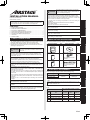
1
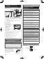
This mark indicates procedures which, if improperly
TM
CAUTION performed, might possibly result in personal harm to
• The “SAFETY PRECAUTIONS” indicated in the manual contain important
information pertaining to your safety. Be sure to observe them.
• For details of the operation method, refer to the operating manual.
• Request the user to keep the manual on hand for future use, such as for
relocating or repairing the unit.
Deutsch
Do not expose this unit directly to water. Doing so will cause trouble,
electric shock, or heating.
Do not set vessels containing a liquid on this unit. Doing so will cause
heating, fire, or electric shock.
Do not insert articles into the slit parts of this unit. Doing so will cause
trouble, heating, or electric shock.
Français
1. SAFETY PRECAUTIONS
Do not touch the switches with sharp objects. Doing so will cause injury,
trouble, or electric shock.
2. MAIN UNIT AND ACCESSORIES
The following installation parts are supplied. Use them as required.
Name and Shape
Q’ty
Name and Shape
This mark indicates procedures which, if improperly
Q’ty
CD-ROM
Wired remote controller
1
WARNING performed, might lead to the death or serious injury
1
of the user.
Perform installation work in accordance with the installation manual.
Request an authorized service personnel to perform installation work.
Do not install this unit by yourself. Improper installation will cause injury,
electric shock, fire, etc.
Perform electrical work by an authorized service personnel in accordance
with the installation manual and the electrical wiring regulations or
implementation regulations of the country. Also do not install this unit by
yourself. Improper electric work will cause electric shock or a fire.
Installation manual
(This manual)
Do not operate this unit when your hands are wet. Touching the unit with
wet hands will cause an electric shock.
When children can approach the unit or touch the unit, take preventive
measures.
Dispose of the packing materials safely. Tear and dispose of the plastic
packing bags so that children cannot play with them. There is the danger
of suffocation if children play with the original plastic bags.
Screw (M4 × 16mm)
2
1
For installing the remote
controller
Operating manual
Cable tie
In the event of a malfunction (burning smell, etc.), immediately stop
operation, turn off the electrical breaker, and consult authorized service
personnel.
Do not install the unit in the following areas:
• Do not install the unit near a source of heat, steam, or flammable gas.
Otherwise, fire could result.
• Area filled with mineral oil or containing a large amount of splashed oil
or steam, such as a kitchen. It will deteriorate plastic parts, causing the
parts to fall.
• Area containing equipment that generates electromagnetic interference.
It will cause the control system to malfunction, and cause erroneous
operation.
• Install the unit in a well-ventilated place avoiding rains and direct
sunlight.
Español
SAFETY PRECAUTIONS .......................................................................1
MAIN UNIT AND ACCESSORIES ...........................................................1
ELECTRICAL REQUIREMENT...............................................................1
SELECTING AN INSTALLATION LOCATION .........................................2
INSTALLING THE REMOTE CONTROLLER .........................................2
SETTING THE REMOTE CONTROLLER...............................................4
TEST RUN ..............................................................................................8
ERROR CODES .....................................................................................8
Italiano
1.
2.
3.
4.
5.
6.
7.
8.
1
1
For remote controller and
remote controller cable
binding
EλληvIkά
CONTENTS
3. ELECTRICAL REQUIREMENT
When connecting the remote controller use the following wiring.
Cable type
Size
Remarks
Sheathed cable
0.33 to
1.25 mm²
Non polar 2 core,
Twisted pair
Shielded cable*
* Use shielded cable in accordance with local rules for remote controller
cable.
Select a flexible cable that can be bound using cable ties from over the
cable sheath inside this unit.
Português
Installation by endusers or not qualified persons can cause harm to
personal safety, can cause severe damage to building and product, can
lead to improper function or reduced lifetime of the equipment.
Русский
PART No. 9373328193-03
Wired Remote Controller
Maximum connectable number of remote controllers by cable size and the
length.
Cable size
AWG
mm²
Max. connectable number of remote
controllers
L* ≤ 100 m
101 m < L*
≤ 250 m
251 m < L*
≤ 500 m
16
1.25
4
4
4
18
0.75 (1.25 > S* ≥ 0.75)
4
4
2
20
0.5 (0.75 > S* ≥ 0.5)
4
2
2
22
0.3 (0.5 > S* ≥ 0.3)
4
1
1
*L: Total cable length, *S: Cable size
En-1
Türkçe
INSTALLATION MANUAL
English
the user, or damage to property.
When detecting the room temperature using the remote controller, please
set up the remote controller according to the following conditions. If the
remote controller is not well set, the correct room temperature will not be
detected, and thus the abnormal conditions like “not cool” or “not heat” will
occur even if the air-conditioner is running normally. :
• A location with an average temperature for the room being air
conditioned.
• Not directly exposed to the outlet air from the air conditioner.
• Out of direct sunlight.
• Away from the influence of other heat sources.
4. SELECTING AN INSTALLATION
LOCATION
If using the remote control sensor, setting is required. Refer to 6.3.5. RC
(Remote Controller) Thermistor Setting.
4. 1. Dimensions and Name of parts
Remote controller unit
(a) (b) (c) (d)
(a)
23
(29/32)
45.3 (1-25/32)
63.5 (2-1/2)
20.4 (13/16)
120 (4-23/32)
120 (4-23/32)
30 (1-3/16) 33 (1-5/16)
83.5 (3-9/32)
Hole: 9 × 4.5
(11/32 × 3/16)
15.3 (19/32)
Unit: mm (in.)
Hole: 12.5 × 4.5
(1/2 × 3/16)
Hole: 6 × 4.5
(1/4 × 3/16)
Room temperature sensor (inside)
(b) On/Off button:
It is possible to operate only while displaying the Monitor Mode screen.
(c)
LED lamp (Operation indicator)
(d) Touch panel display
Monitor mode screen
The home screen of this unit.
Except for in the following
cases, the screen will go back
to the main screen if there is
no operation for over 10 min.
(Unsaved settings will be
cancelled.)
• In Emergency Stop.
• In Transferring data.
• In checking the indoor unit
position
• In Function Setting
(a)
(a)
(b)
Office
(d)
(c)
Fri 10:00AM
Fan
Set Temp.
Mode
26.0
Cool
°C
Room Temp.
Status
Auto
26.0°C
Menu
(d)
(e)
(f)
(g)
(h)
WARNING
Always use the accessories and specified installation work parts. Check
the state of the installation parts. Not using the specified parts will cause
units to fall off, water leakage, electric shock, fire, etc.
Install at a place that can withstand the weight of the unit and install
positively so that the unit will not topple or fall.
When installing this unit, make sure that there are no children nearby.
Otherwise, injury or electric shock could result.
Before starting installation work, turn off the power of this unit and the
connection destination. Do not turn on the power again until installation is
completed. Otherwise, it will cause electric shock or fire.
Use the accessories or specified power supply cable and remote controller
cables. Do not modify power supply cable and remote controller cables
other than those specified, do not use extension cords, and do not use
independent branch wiring. Overcurrent may cause electric shock or fire.
Install the remote controller cables securely to the terminal block. Confirm
that external force is not applied to the cable. Use remote controller cables
made of the specified wire. If intermediate connection or insertion fixing
are imperfect, it will cause electric shock, fire, etc.
When connecting the remote controller cable, route the cables so that the
rear case of this unit is securely fixed. If the rear case is imperfectly fixed,
it may cause fire or overheating of the terminals.
Perform functional earthing work positively. Do not connect the functional
earthing wire to a telephone earth (Ground) wire, water pipe, or conductor
rod.
Always fasten the outside covering of the connection cable with the cable
tie. If the insulator is chafed, electric discharge may occur.
(i)
(d)
Set Temp.: Set the operating temperature. Refer to operating manual.
CAUTION
Do not set the DIP switch or rotary switch of this unit except as specified
in this manual or the operating manual supplied with the air conditioner.
Setting the switches other than specified will cause an accident or trouble.
Use an insulated screwdriver to set the DIP switches.
(b) R.C. Group name: Refer to 6.3.4.
(c)
5. INSTALLING THE REMOTE
CONTROLLER
Mode: Set the operation mode. Refer to operating manual.
(d) Status icons: Refer to operating manual.
Before opening the case of this unit, completely discharge static electricity
charged on you body. Not doing so will cause trouble.
(e)
Clock: Refer to 6.2.4.
Do not touch the circuit board and circuit board parts directly with your
hands. Otherwise, injury or electric shock could result.
(f)
Fan: Set the fun speed. Refer to operating manual.
Do not overtighten the screws. It will cause damage of this unit.
(g) Room temperature: Refer to 4.2. and 6.3.5.
(h) Menu: Set the various settings.
(i)
Status: Check the status of indoor unit and error.
This product uses a Bitmap font made and developed by Ricoh Company, Ltd.
4. 2.
SETTING THE ROOM TEMPERATURE
DETECTION LOCATION
CAUTION
As the temperature sensor of remote controller detects the temperature near
the wall, when there is a certain difference between the room temperature
and the wall temperature, the sensor will not detect the room temperature
correctly sometimes. Especially when the outer side of the wall on which the
sensor is positioned is exposed to the open air, it is recommended to use the
temperature sensor of the indoor unit to detect the room temperature when
the indoor and outdoor temperature difference is significant.
The detection location of the room
temperature can be selected from the
following 2 methods. Choose the detection
location that is best for the installation
location.
The temperature sensor of the indoor unit or
the remote controller can be used to detect
the room temperature.
A sensor of the indoor
unit (inside)
Install the remote controller cables 1 m away from television and radio to
avoid distorted images and noise.
Confirm the name of each terminal block of the unit and connect the wiring
in accordance with the directions given in the manual. Improper wiring
work will damage the electric parts and cause smoke and fire.
When installing the connection cable near a source of electromagnetic
waves, use shielded cable. Otherwise, a breakdown or malfunction could
result.
5. 1. Wiring types
5.1.1. Single control
Indoor unit
When there is a
functional earthing
Remote controller
A sensor of the remote
controller (inside)
En-2
Be careful so that the front case does not fall after the front case screws
are removed. Otherwise, injury could result.
5.1.2. Group control
With a single remote controller, up to 16 units can be simultaneously
operated.
Indoor unit 0 Indoor unit 1 Indoor unit 2 Indoor unit 3
Y1 Y2 Y3
When there is a
functional earthing
Before using this product, always set DIP switch to “ON”. If not set, when
the main power is turned on again, the set data by menu operation will be
erased and cause erroneous operation.
[DIP Switch]
• Performs the enabling/disabling of the backup function by the internal
battery.
• It is disabled when shipped from the factory to prevent consumption of
the charge.
5. 3. Installation
Remote controller
5.3.1. Install the rear case
A. When mounting on the box:
5.1.3. Multiple remote control
Remote controller cable
Up to 4 remote controllers can be used to operate the indoor units.
Multiple installation method described above is prohibited to combine with
UTY-RNK* (3 Wired type) or UTY-RSK* (3 Wired type) or UTY-RHK*
(3 Wired type) and UTY-RNR* (2 Wired Type).
Connector
Indoor unit
Box
Screws
When there is a
functional earthing
Rear case
Remote
controller
Remote
controller
B. When the cable is along the wall:
Cut off
Cable cover
(more than 1
mm thick)
Epoxy putty
Group control and multiple remote control can be used together.
5. 2. Preparing for Installation
Rear case
5.2.1. Strip of the remote controller cable
Sheathed
cable
A
Shielded
cable
B
A
B
Functional
earthing
C
A: 7 mm (9/32 in.), B: 7 mm (9/32 in.), C: 25 mm (31/32 in)
5.2.2. Remove the front case
When open the remote controller, remove the connector from the front
case. The cables may break if the connector is not removed and the front
case hangs down. When installing the front case, connect the connector to
the front case. When removing and connecting the connector, be careful
not to break the cables.
Release the claws (2 places) with a flat-blade screwdriver, and separate the
front case and rear case.
Front case
Lightly lift the
front case.
Rear case
Flat-blade
screwdriver
Claws (2 places)
Disconnect the connection cable connector from the connector of the front
case PC board (printed circuit board).
5.3.2. Connecting the remote controller cable
CAUTION
When connecting a remote controller cable to the remote controller
terminal block, please use the specified torque to tighten screws. If you
over-tighten screws, they will break the terminal unit.
Be careful to avoid breaking the cable by over-tightening the cable tie.
Tightening torque
0.8 to 1.2 N•m (8 to 12 kgf•cm)
Fasten the outside covering of the connection cable with the cable tie.
Tighten the cable tie firmly so that pulling force does not propagate to the
terminal connection even if force of 30 N is applied to the cable.
Select a flexible cable that can be bound using cable ties from over the
cable sheath inside this unit.
Cable tie
Front case
(back side)
Rear
case
Connector
Functional earthing (If necessary)
GOOD
PROHIBITED
5.2.3. Setting the DIP switch
CAUTION
5.3.3. Attach the front case
Use an insulated screwdriver to set the DIP switches. Do not touch the
DIP switch with your hands.
Front case (back side)
Set the DIP switch to ON
Connect the connection cable connector to the
connector of the front case PC board. Insert after
adjusting upper part of front case. Otherwise, there
is a risk of damage to the internal parts of this unit.
When you attach the front case, make sure that the
cables are not being pinched by front case.
(1)
(2)
ON
OFF ON
En-3
5. 4. Connecting to the indoor unit
6. SETTING THE REMOTE CONTROLLER
6. 1. Initialization procedure
CAUTION
When connecting the remote controller cable to the indoor unit, do not connect
it to the outdoor unit or the power terminal block. It may cause a failure.
When switching the DIP switch (SW1) on the indoor unit PC board, be
sure to turn off the power supply to the indoor unit. Otherwise, the PC
board of the indoor unit may be damaged.
There are 2 methods to connect the remote controller cable to the indoor
unit. One is the connection using connecting cable (Included in the
indoor unit), and the other is the connection the remote controller cable is
connected to the exclusive terminal block of the indoor unit.
(For the details, refer to the installation manual of the indoor unit to be used.)
After remote controller installation work is complete, perform initialization
using the following procedures before starting to use the system.
Turn on the
power
6.2.1. Turn on the power ..................................... 4
Setting of first
time start
6.2.2.
6.2.3.
6.2.4.
6.2.5.
Language Setting ...................................... 4
R.C. Master/Slave Setting......................... 5
Date and Time Setting .............................. 5
Temperature Unit Setting .......................... 5
Initial setting
6.3.4.
6.3.5.
6.3.6.
6.3.7.
6.3.8.
R.C. Group Name Setting ......................... 6
R.C. Sensor Setting .................................. 6
Master Indoor Unit Setting ........................ 6
Password Setting (administrator password) ... 6
Display Item Setting .................................. 6
Other Settings
6.4.1
6.4.2.
6.4.3.
6.4.4.
6.4.5.
6.4.6.
6.4.7.
6.4.8.
6.4.9.
6.4.10.
Error History .............................................. 7
Setting Status List ..................................... 7
Filter Sign Reset ....................................... 7
Version ...................................................... 7
Test Run ................................................... 7
RC Address Setting .................................. 7
I.U. Address Verification ........................... 8
Function Setting ........................................ 8
Installer Password Change ....................... 8
Initialization ............................................... 8
5.4.1. When connecting to the connector
(1) Use a tool to cut off the terminal on the end of the remote controller cable,
and then remove the insulation from the cut end of the cable as shown
in Fig. 1. Connect the remote controller cable and connecting cable as
shown in Fig. 2. Be sure to insulate the connection between the cables.
Fig.1
Fig.2
White
Connecting
cable
Red
20 mm
Insulated
Black
connection
Remote
controller cable
(Non-polar)
Cut and
insulate
(2) Connect the remote controller cable to the connecting cable, and insert
it to the connector. Set to “2WIRE” the DIP switch (SW1) on the PC
board of the indoor unit.
Set to "2WIRE" the
DIP switch (SW1)
Connect to earth
(ground) screw
Remote controller
cable (Non-polar)
Functional earthing
(If necessary)
Connecting cable
* Layout of Connector and PC
board is varies, depending on
the type of indoor unit.
Connector
(adapter)
Indoor unit
PC board
Connector CNC01
(onboard)
SW1
Indoor unit
PC board
Initialization end
After installing this unit, perform the test run to confirm that the unit is
operating properly. Then, explain the operation of this unit to the customer.
6. 2. Setting of first time start
6.2.1. Turn on the power
CAUTION
Recheck the wiring. Incorrect wiring will cause trouble.
5.4.2
When connecting to exclusive terminal block
(1) Connect the end of remote controller cable directly to the exclusive
terminal block. Set to “2WIRE” the DIP switch (SW1) on the PCB (printed
circuit board) of the indoor unit.
Terminal block
Functional earthing
(If necessary)
Indoor unit
PC board
Remote controller
cable (Non-polar)
* Layout of terminal block and
PC board is varies, depending
on the type of indoor unit.
Set to "2WIRE" the
DIP switch (SW1)
When initially starting up this unit, the following setting screen will be
displayed. Settings configured at this stage can be changed afterwards.
If an error screen is displayed, shut down all
unit power, and check the connections. After
resolving the problem, turn on the power again.
Error
Code 01
If “Please set the address correctly.” is
displayed, touch [Close], and the “RC
Address Setting” screen (refer to 6.4.6) will be
displayed. After setting, please restart this unit.
Error (code:XX.X)
Please set the address correctly.
Close
GOOD
PROHIBITED
6.2.2. Language Setting
1. The “Language Setting” screen has two pages. ou can move between
the pages by touching [Next Page] or [Previous Page]. Touch the
language to be used. Touch [OK] to display the “R.C. Master/ Slave
Setting” screen.
Diameter of cables
are different
Connect the cables
to 1 side
Tightening torque
M3 screw
(Remote controller / Y1, Y2)
En-4
0.5 to 0.6 N·m
(5 to 6 kgf·cm)
Language Setting
Page 1/ 2
Francais
English
Ё᭛
Deutsch
Espanol
Cancel
Next
Page
Language Setting
Page 2/ 2
Русский
Jezyk
polski
OK
Cancel
Previous
Page
OK
6.2.3. R.C. Master/Slave Setting
1.
1.
(a) If the remote controller is a single
connection, this setting is omitted.
Proceed to “6.2.4. Data and Time Setting”.
(b) If a remote controller has multiple
connections, and if “Master” is initially
set, all other units will be set to “Slave”.
Mode
Master
OK
back to the “Date and Time Setting” screen.
3. Touch the [Time] on the “Date and Time Setting” screen. The “Time”
screen is displayed.
Date
Time
10:00 AM
Day/Month/Year
12:00-11:59AM/PM
Disable
Date Format
Time Format
Summer Time Setting
Cancel
3.
Fri 10:00AM
Day
Month
14
Year
9
OK
2012
Cancel
Date and Time Setting
Time
10:00 AM
Cancel
Day/Month/Year
12:00-11:59AM/PM
Disable
AM
Cancel
Temp. Unit
Setting
R.C.Group
Name Setting
Password Setting
Next
Page
Master Indoor
Unit Setting
Page 3/ 3
RC Master/
Slave Setting
Display Item
Setting
Previous
Page
Back
Initial Setting
Next
Page
Previous
Page
Back
Date Setting
Date and Time Setting
Display Format Setting
Back
When settings for all items are complete, the screen will return to the
home screen. touch [Back] to return to the “Initial Setting” screen.
• Date and Time Setting
Date and Time Setting
Fri 10:00AM
Date
Time
14/ 9/2012
10:00 AM
min.
40
Page 2/ 3
R.C. Sensor
Setting
Setting” screen. The “Date Setting” screen
is displayed.
Select and touch “Date and Time Setting”
or “Display Format Setting”.
OK
5.
8
Initial Setting
Page 1/ 3
Date Setting
1. Touch the [Date Setting] on the “Initial
“Temperature Unit Setting” screen.
hour
Maintenance
Previous
Page
6.3.2. Date Setting
5. Touch [OK] on the “Date and Time Setting” screen to display the
Fri 10:00AM
Initial Setting
Monitor
Touch the [Language Setting] on the “Initial Setting” screen. The “Language
Setting” screen is displayed.
For the method of setting language, refer to 6.2.2. Language Setting. Select
the language to be used, and touch [OK] on “Language Setting” to go back
to the “Initial Setting” screen.
back to the “Date and Time Setting” screen.
Time
Preference
6.3.1. Language Setting
4. Touch [ ] or [ ] to set hours, minutes, and AM/PM. Touch [OK] to go
4.
Next
Page
Page 2/ 2
Summer Time
Setting
Fri 10:00AM
Date
14/ 9/2012
Date Format
Time Format
Summer Time Setting
OK
Special Setting
Monitor
Language Setting
Back
2.
Weekly Timer
Setting
Main Manu
[Previous Page] to switch between screens. Touch the items you wish
to configure.
screen is displayed.
Date
Timer Setting
Menu
Initial Setting
2. Touch [ ] or [ ] to set the year, month, and date. Touch [OK] to go
Page 1/ 2
Air Flow Direction
Setting
3. The “Initial Setting” screen has three pages. Touch [Next Page] or
1. Touch the [Date] on the “Date and Time Setting” screen. The “Date”
14/ 9/2012
Fan
Status
6.2.4. Date and Time Setting
Fri 10:00AM
Set Temp.
Slave
Cancel
Touch [OK] to display the “Date and Time Setting” screen.
Date and Time Setting
Main Manu
Fri 10:00AM
Please set only one Master remote controller. Units other than Master are
set to Slave automatically.
When remote controllers are set to “Slave”, setting items will be restricted.
1.
2.
R.C. Master / Slave Setting
Date Format
Time Format
Summer Time Setting
OK
Day/Month/Year
12:00-11:59AM/PM
Disable
Cancel
OK
Touch the [Date and Time Setting] on the “Date Setting” screen. The “Date
and Time Setting” screen is displayed.
For the method of configuration, refer to 6.2.4. Date and Time Setting. Set
all required items, and touch [OK] on the “Date and Time Setting” screen to
return to the “Initial Setting” screen.
• Display Format Setting
6.2.5. Temperature Unit Setting
1. Touch the [Date Format] on the “Display Format Setting” screen. The
“Date Format” screen is displayed.
1. Select and touch [°C] or [°F] and touch [OK].
2. When initial start-up setting is complete, the screen on the right will
be displayed.This screen is the “Monitor mode screen”, which is the
home screen of this unit.
1.
2. Select and touch the data display format. Touch [OK] on the “Date
Format” screen to return to the “Display Format Setting” screen.
3. Touch the [Time Format] on the “Display Format Setting” screen. The
“Time Format” screen is displayed.
2.
1.
Temperature Unit Setting
2.
Set Temp.
Fan
°C
Display Format Setting
Fri 10:00AM
Date Format
Date Format
Status
Cancel
6. 3. Initial setting
Configure settings required at the time of installation. For details of the
setting, refer to the operating manual on the attached CD-ROM.
This unit has two kinds of passwords; password for administrators and
password for installers. Password for administrators cannot be used for the
settings related to the installation of this unit.
Password Verification
Enter Current Password
Installer password can be used to configure all of
setting for this unit.
1
2
3
4
0
CL
When “Password (Installer Password)
5
6
7
8
9
Verification” screen is displayed, enter the
Cancel
OK
password (installer password) and touch [OK].
The default password is “0000” (4 digits).
1. Touch the [Menu] on the “Monitor Mode screen”. The “Main Menu”
screen is displayed.
2. The “Main Menu” screen has two pages. Touch [Next Page] or
[Previous Page] to switch between screens. Touch the [Initial Setting].
OK
Cancel
Fri 10:00AM
Date Format
Time Format
Year/Month/Day
12:00–11:59AM/PM
Menu
Display Format Setting
Day/Month/Year
Month/Dat/Year
Time Format
OK
Fri 10:00AM
Day/Month/Year
Day/Month/Year
°F
Cancel
3.
Fri 10:00AM
Mode
12:00–11:59AM/PM
OK
Cancel
OK
4. Select and touch the data display format. Touch [OK] on the “Time
Format” to return to the “Display Format Setting” screen.
5. Touch [OK] on the “Display Format Setting” screen to return to the
“Date Setting” screen.
4.
5.
Time Format
Fri 10:00AM
Display Format Setting
0:00–11:59 AM/PM
0:00–23:59
Cancel
Fri 10:00AM
Date Format
12:00–11:59 AM/PM
Day/Month/Year
Time Format
12:00–11:59AM/PM
OK
Cancel
OK
6.3.3. Temperature Unit Setting
Touch the [Temperature Unit Setting] on the “Initial Setting” screen. The
“Temperature Unit Setting” screen is displayed.
For how to configure, refer to 6.2.5. Temperature Unit Setting. Set
temperature units and touch [OK] on the “Temperature Unit Setting” to return
to the “Initial Setting” screen.
En-5
6.3.4. R.C. Group Name Setting
Touch the [R.C. Group Name Setting] on the “Initial Setting” screen. The “R.C.
Group Name Setting” screen is displayed.
4. Touch the [Change Setting] on the
• About the “R.C. Group Name Setting” screen
Touch the relevant key and enter
a name. Touch [OK] to return to
the (a) R.C. Group Name Setting
ABCDEFGHIJKL│ Over Cancel
OK “Initial Setting” screen after
displaying the “Confirmation
screen”.
(a)
Change Setting
(a)
Back
ABCDEFGHIJKLM│
(b)
Over
ABC
DE
FGH
IJ
KLM
NO
PQR
ST
UVW
XY
Z./
_–
0–9
Fixed
Phrase
(c)
Cancel
SP
(d)
(e)
(f)
BS
5. The “Change Setting” screen is 3 pages, it can be changed by the
[Previous Page] or [Next Page].
Items set to be [ON] require the administrator password to open the
setting screen.
OK
Fixed Phrase key: Floor, Corridor, Office, Conf Room, Recept
Room, Room, Room No., Front, Side, Entrance, Outlet, East, West,
South, North, Window are registered. Touch the [Fixed Phrase] key
until the sentence you wish to use is displayed.
Backspace key
Cursor keys
Change Setting
Page 2/ 3
[Off]
Weekly Timer
[On]
Anti Freeze
[On]
Off Timer
[Off]
Set Temp. Auto Return
[On]
Initial Setting / Maintenance
[On]
[Off]
Set Temp. Range Setting
Auto Off Timer
Next
Page
Cancel
OK
Cancel
Previous
Page
Change Setting
Page 3/ 3
[On]
Next
Page
OK
Cancel
Previous
Page
OK
6. Touch the relevant item to display the setting screen. Touch [OK] after
touching [ON] to return to the “Change Setting” screen.
Touch [OK] on the “Change Setting” screen after setting relevant
items to return to the password setting screen.
(d) Space key
(f)
Page 1/ 3
On Timer
Change Setting
Input area: If the number of input characters exceeds that permitted,
“Over” will be displayed on the right side.
(e)
Change Password
R.C.Group Name Setting
(b) Character keys: Touch the same key until the character you wish to
use is displayed.
(c)
Password Setting
“Password Setting” screen. The “Change
Setting” screen is displayed.
7. Touch the [Back] on the “Password Setting”. It returns to the “Initial
Setting” screen.
6.
6.3.5. RC Sensor Setting
On Timer
1. Touch the [RC Sensor Setting] on the
R.C. Sensor Setting
“Initial Setting” screen. The “RC Sensor
Setting” screen is displayed.
If a remote-control sensor is used, touch
[Used]. Touch [OK] to return to the “Initial
Setting” screen.
Password Setting
On
Change Password
Used
Off
Change Setting
Not Used
Cancel
Cancel
OK
Back
OK
6.3.6. Master Indoor Unit Setting
• One of the multiple indoor units connected to the same refrigerant system
or RB unit can be set as the “master unit”.
• The indoor unit defined as the "master unit" determines the priority mode
(cool or heat) within the refrigerant system or RB group.
6.3.8. Display Item Setting
• Filter Sign
Set to “Visible” to display icons on the “Monitor mode screen” during the
indoor unit filter cleaning period.
1. Touch the [Display Item Setting] on the “Initial Setting” screen. The
“Display Item Setting” screen is displayed.
Then touch the [Filter Sign] on the “Display Item Setting” screen. The
“Filter Sign” screen is displayed.
• Switch setting on the outdoor unit or RB unit that is connected to the
indoor units. Refer to the installation manual of outdoor unit or RB unit.
1. Touch the [Master Indoor Unit Setting] on the “Initial Setting” screen.
The “Master Indoor Unit Setting” screen is displayed.
To set a unit as the Master Indoor Unit, touch [Set].
2. Touch [OK] after touching [Visible] or [Invisible] to return to the “Display
Item Setting” screen.
1.
2. Touch [Yes] when the confirmation screen is displayed to return to the
“Master Indoor Unit Setting” screen.
1.
7.
2.
Display Item Setting
Filter Sign
Filter Sign
Visible
[Visible]
2.
Room Temp.
Master Indoor Unit Setting
Cancel
Not Master Indoor Unit
Back
The connected indoor unit will be
set as the master indoor unit. OK?
Set
No
The “Room Temperature” screen is displayed.
4. Touch [OK] after touching [Visible] or [Invisible] to return to the “Display
Item Setting” screen.
5. Touch the [OK] on the “Display Item Setting”. It returns to the “Initial
Setting” screen.
3.
Filter Sign
Room Temp.
The default password is “0000” (4 digits).
Cancel
3. Enter the new password, then touch the [OK]. It returns to the
“Password Setting” screen.
2.
3.
Password Verification
Change Password
Enter Current Password
Enter New Password
Change Password
Back
En-6
0
1
2
3
4
5
6
7
8
9
Cancel
OK
4.
Display Item Setting
2. Enter the current password, then touch the [OK].
CL
OK
3. Touch the [Room Temperature] on the “Display Item Setting” screen.
Set or change the administrator password.
1. Touch the [Password Setting] on the “Initial Setting” screen. The
“Password Setting” screen is displayed.
Then touch the [Change Password] on the “Password Setting”
screen. The “Change Password” screen is displayed.
Change Setting
Cancel
Set to “Visible” to display the room temperature detected by this unit on the
monitor screen.
6.3.7. Password Setting (administrator password)
Password Setting
Invisible
OK
• Room Temperature
Yes
When changing the Master Indoor Unit, another indoor unit cannot be
made the master indoor unit unless the settings of the current master
indoor unit are cancelled beforehand.
(“Reset” cannot be performed while the indoor unit is operating.)
1.
[Invisible]
Master Indoor Unit Setting
Master Indoor Unit Setting
CL
0
1
2
3
4
5
6
7
8
9
Cancel
OK
5.
Display Item Setting
Room Temp.
[Visible]
Visible
Filter Sign
[Invisible]
Invisble
Room Temp.
OK
Cancel
OK
Cancel
[Visible]
[Visible]
OK
6.3.9. RC Master/Slave Setting
6.4.3. Filter Sign Reset
If multiple remote controllers are set for a remote-control group or for a
single indoor unit, it is necessary to set the remote-controller master. This
setting will be required at the time of initial start-up during installation.
However, this setting can be changed afterwards. No master remote
controllers will be automatically set to be slaves. The following functions can
be used with slave remote controllers.
For the method of configuration, refer to 6.2.3. RC Master Slave Setting.
Setting. Touch [OK] on the “RC Master/Slave Setting” screen after setting
the temperature units to return to the “Initial setting” screen.
Do not perform “RC Mater/Slave Setting” during setting or operating from
the Master unit.
1. Touch the [Filter Sign Reset] on the
“Maintenance” screen. The “Filter Sign
Reset” screen is displayed.
Touch [OK] to reset the filter sign, and
return to the Maintenance screen.
Filter Sign Reset
The filter sign will be reset. OK?
Cancel
6.4.4. Version
1. Touch the [Version] on the “Maintenance”
screen. The “Version” screen is displayed.
Touch [Back] to return to the “Maintenance”
screen.
Version
V000E00P00L00
Back
6. 4. Maintenance (Other Settings)
6.4.5. Test Run
Carry out the following setting and confirmation, as required.
1. Touch the [Menu] on the “Monitor mode screen”. The “Main Menu”
screen is displayed.
Carry out a test run after completing configuration.
1. Touch the [Test Run] on the “Maintenance”
2. The “Main Menu” screen has two pages. Touch [Next Page]
screen. The “Test Run” screen is
displayed.
Touch [OK] to return to the Maintenance
screen, and start a test run. The test run
will automatically end in approximately 60
min.
or [Previous Page] to switch between screens. Then touch the
[Maintenance]
1.
2.
Fri 10:00AM
Mode
Set Temp.
Fan
Status
Menu
Main Manu
Page 1/ 2
Main Manu
Page 2/ 2
Air Flow Direction
Setting
Timer Setting
Summer Time
Setting
Preference
Weekly Timer
Setting
Special Setting
Initial Setting
Maintenance
Next
Page
Monitor
Monitor
has 3 pages. Touch [Next Page] or [Previous Page] to switch between
screens.
Page 1/ 3
Maintenance
Page 2/ 3
Error History
Setting
Status List
Test Run
R.C. Address
Setting
Filter Sign
Reset
Version
I.U. Address
Setting
Function Setting
Next
Page
Back
6.4.1
Next
Page
Previous
Page
Back
Maintenance
Initialization
• Checking the remote controller address
1. Touch the [R.C. Address Setting] on the
“Maintenance” screen. The “R.C. Address
Setting” screen is displayed.
The “Current Address” is displayed as
[System-Unit]. The value for “Unit” refers
to the remote-control address.
Previous
Page
History” screen is displayed.
If there are 7 or more errors, you can switch between pages by
touching [Next Page] or [Previous Page] Up to a maximum of 32
errors can be saved. Once there are more than 32 errors, the oldest
one will be deleted.
Touch [Back] to return to the “Maintenance” screen.
2. To delete the error history, touch [Erase All] and then [Yes] on the
confirmation screen.
2.
No.
1
2
3
4
5
6
Date
2012/
2012/
2012/
2012/
2012/
2012/
Back
8/ 1
7/30
7/25
7/22
7/22
7/21
Time
11:00 AM
2:53 AM
8:53 AM
11:00 AM
11:00 AM
11:00 AM
Address
002-01
002-02
002-02
002-01
002-01
002-01
Next
Page
Page 1/ 2
Code
141
143
143
141
141
141
Error History
Erase
All
OK
Addresses will be automatically set when initially starting up this unit. In
such a case, do not change the remote-control address for the indoor unit,
and keep it at the initial setting of 0.
R.C.Address Setting
[001–01]
Current Address
Manual Addressing
Address Reset
Back
Touch [Back] to return to the “Maintenance” screen.
1. Touch the [Error History] on the “Maintenance” screen. The “Error
Error History
Cancel
If you wish to cancel the test run before it is complete, return to the
“Monitor Mode screen”, and touch the On/Off button.
Error History
1.
The test run will be performed. OK?
Page 3/ 3
Installer Password
Change
Back
Test Run
6.4.6. R.C. Address Setting
Previous
Page
3. The “Maintenance” screen is displayed. The “Maintenance” screen
Maintenance
OK
When the address is set manually, this mark
is displayed.
• Manual Address Setting
Only set addresses manually when using different numbers for addresses.
A remote-controller address for the indoor unit needs to be set.
Set the remote-control addresses for the indoor units which are connected
using the same remote-control cable with a range from 1 to 9 and from A
(10) to F(15), without any duplicates. (Do not use “0” for configuration).)
For how to configure the remote control addresses for the indoor unit,
refer to its work manual.
Delete entire error history?
1. Touch the [RC Address Setting] on the “Maintenance” screen. The
No
“R.C. Address Setting” screen is displayed.
Touch the [Manual Addressing]. The “Manual Addressing” screen is
displayed.
Yes
6.4.2. Setting Status List
1. Touch the [Setting Status List] on the
“Maintenance” screen. The “Setting Status
List” screen is displayed.
Touch [Next Page] or [Previous Page] to
switch between screens.
Touch [Back] to return to the “Maintenance”
screen.
2. Touch [ ] or [ ] to set the addresses of this unit. Touch [OK] to
Setting Status List
On Timer
– Operation Start Time
Off Timer
– Operation Stop Time
Auto Off Timer
– Operation Stop Time
– Time Range
Back
display the confirmation screen, and touch [Yes] to return to the RC
Address setting screen.
If you wish to carry out configuration again, touch [Address Reset] on
the “R.C. Address Setting”.
Page 1/ 5
[Disable]
[0.5hr]
[Disable]
[0.5hr]
[Disable]
[30min.]
[–]
Next
Page
1.
2.
R.C.Address Setting
Manual Addressing
[001–01]
Current Address
Manual Addressing
System
Unit
001
01
Address Reset
Back
Cancel
OK
The address for this unit can be set from 1 to 32. However, do not set
the same number as that for the remote-control address of an indoor unit
connected using the same remote-control cable.
En-7
6.4.7. I.U. Address Verification
6.4.9. Installer Password Change
Check the address and position of the indoor unit.
Change the Installer password.
1.
Touch the [I.U. Address Verification] on the “Maintenance” screen.
The “I.U. Address Verification” screen is displayed.
If there are multiple pages, you can switch between them by touching
[Next Page] or [Previous Page].
Touch [Check] to display the indoor unit address checking start
screen.
1. Touch the [Installer Password Change] on the “Maintenance” screen.
The “Installer Password Verification” screen is displayed.
Enter the current password, then touch the [OK].
The default password is “0000” (4 digits).
2. The “Installer Password Change” screen is displayed.
Enter the new password, then touch the [OK]. It returns to the
“Maintenance” screen.
2. Touch [Yes] to display the confirmation screen.
1.
3. Select the indoor unit to be checked. If there are multiple pages,
you can switch between them by touching [Next Page] or [Previous
Page]. The selected indoor unit will start to blow air and flash a LED*.
(*Only when the indoor unit has the relevant functions)
Touch [Back] on the confirmation screen to return to the previous
screen.
1.
2.
I.U. Address Verification
No.
1
2
3
4
5
6
System–Unit
002–1
002–2
002–3
002–4
002–5
002–6
/
/
/
/
/
/
/
Indoor unit position will be checked. OK?
Next
Page
Back
Check
No
System–Unit
Page 1/ 2
/ 01–01
2 002–2
/ 01–02
3 002–3
/ 01–03
No.
1
2
3
4
5
6
System–Unit
002–1
002–2
002–3
002–4
002–5
002–6
/
/
/
/
/
/
/
Check
6.4.8. Function Setting
This procedure changes the function settings used to control the indoor unit
according to the installation conditions. Incorrect settings can cause the
indoor unit to malfunction. Perform the “Function Setting” according to the
installation conditions using the remote controller.
• Refer to the indoor unit installation manual for details on the function
numbers and setting numbers.
• Prepare for setting of indoor unit referring to installation manual of indoor
unit before start of functional setting.
“Function Setting” screen is displayed.
Touch the [Address] on the “Function Setting” screen. The “Address”
screen is displayed.
2. Touch [ ] or [ ] to select the address of the indoor units to be
Function No.
[00]
Setting No.
Back
Address
Cancel
[002–1]
Function No.
OK
Back
0
1
2
3
4
5
6
7
8
9
Cancel
OK
[00]
1. If an error occurred, an error icon appears on the “Monitor mode
screen”.
Touch the [Status] on the “Monitor mode screen”. The “Status” screen
is displayed.
1.
2.
Fri 10:00AM
3.
Mode
Set Temp.
Fan
Status
Page 1/ 3
Air Flow Direction
VT
Setting
“Function Setting” screen.
6.
Address
Cancel
OK
Function Setting
[002–1]
Function No.
[00]
Setting No.
Setting No.
[00]
00
Back
Setting
7. Touch [Back] to return to the “Maintenance”
screen.
Cancel
OK
[002–1]
[00]
Setting No.
[00]
Setting
14,15, 41, 44
Monitor
Off
Next
Page
Error code
Error
Information
Back
Next
Page
Contents
CC.1
Sensor error
C2.1
Transmission PCB error
12.1
Wired remote controller communication error
12.3
Number excess of device in wired remote controller
system
29.2
Connection unit number error (Remote controller)
26.4
Address duplication in wired remote controller system
26.5
Address setting error in wired remote controller system
15.4
Data acquisition error
[00]
Function No.
Back
En-8
[002–01]
Function Setting
Address
Error Code
3
For the details of the indoor unit or outdoor unit error when checking the
error contents, refer to the error codes in each installation manual.
6. Touch [ ] or [ ] to set the setting number. Touch [OK] to return to the
00
Menu
Page 1/ 5
02-01
Anti Freeze
Off
Status
Error Information
Address
HZ
1
screen is displayed.
Address
Function No.
OK
[00]
5. Touch the [Setting] on the “Function Setting” screen. The “Setting”
5.
Cancel
8. ERROR CODES
the “Function Setting” screen.
Function Setting
Remote controller will be initialized
to the factory default setting. OK?
For how to carry out a test run, refer to 6. 4. Maintenance (Other Settings)
→ 6.4.5. Test Run.
4. Touch [ ] or [ ] to set the function number. Touch [OK] to return to
Function No.
Initialization
7. TEST RUN
Economy
4.
OK
below.
Touch the [Next page] (or [Previous page]) to switch to other unit
information.
Setting No.
Setting
CL
• Test run method of the indoor unit is explained.
• Refer to the indoor unit installation manual for the list of items to check.
Function Setting
[00]
9
When relocating the set remote controller, initialize it.
3.
002–01
8
3. 2-digit numbers are corresponding to the error code in the table
“Function No.” screen is displayed.
All
7
Information” screen is displayed. (If there are no errors, the [Error
Information] will not be displayed.)
3. Touch the [Function No.] on the “Function Setting” screen. The
Address
6
2. Touch the [Error Information] on the “Status” screen. The “Error
configured. (To set all indoor units at the same time, touch [All].)
Touch [OK] to return to the Function Setting screen.
[002–1]
5
Check the error
1. Touch the [Function Setting] on the “Maintenance” screen. The
Address
4
“Maintenance” screen. Enter the Installer
password. The “Initialization” screen is
displayed.
When the [OK] is touched, this unit restarts
automatically after initialization. Perform
each setting.
Page 1/ 2
Ref.–In.
01–01
01–02
01–03
01–04
01–05
01–06
Next
Page
Back
Function Setting
3
6.4.10. Initialization
Next
Page
I.U. Address Verification
2.
2
1. Touch the [Initialization] on the
End
Verification Screen” to return to the
Maintenance Screen.
1
Require an Installer password.
/ Ref.–In.
1 002–1
Yes
4. Touch [Back] on the “IU Address
1.
CL
0
Cancel
I.U. Address Verification
No.
Enter New Password
Enter Current Password
3.
I.U. Address Verification
Page 1/ 2
Ref.–In.
01–01
01–02
01–03
01–04
01–05
01–06
2.
Installer Password Change
Installer Password Verification