1
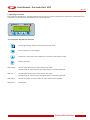
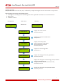
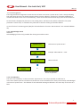
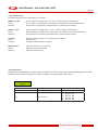
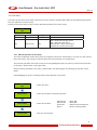
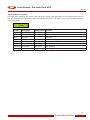
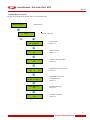
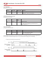
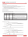
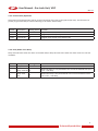
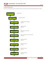
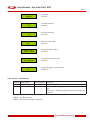
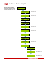
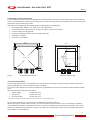
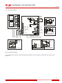
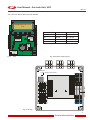
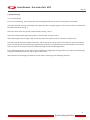
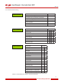
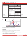
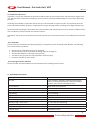
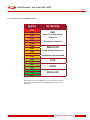
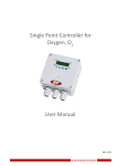
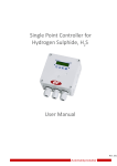
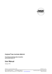
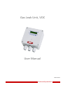
Gas Leak Unit, VOC
User Manual
March 2013
Automatikprodukter
User Manual - Gas Leak Unit, VOC
Mar 12
Table of contents
1. Intended Use . . . . . . . . . . . . . . . . . . . . . . . . . . . . . . . . . . . . . . . . . . . . . . . . . . . . . . 4
1.1 Normal Mode . . . . . . . . . . . . . . . . . . . . . . . . . . . . . . . . . . . . . . . . . . . . . . . . . . . . . 4
1.2 Alarm Mode. . . . . . . . . . . . . . . . . . . . . . . . . . . . . . . . . . . . . . . . . . . . . . . . . . . . . . 4
1.3 Fault Mode. . . . . . . . . . . . . . . . . . . . . . . . . . . . . . . . . . . . . . . . . . . . . . . . . . . . . . . 4
2 Operating Instruction. . . . . . . . . . . . . . . . . . . . . . . . . . . . . . . . . . . . . . . . . . . . . . . . . . 5
2.1 Description Keypad User Interface. . . . . . . . . . . . . . . . . . . . . . . . . . . . . . . . . . . . . . . . . . 5
2.2 Setting / Changing Parameters or Set points . . . . . . . . . . . . . . . . . . . . . . . . . . . . . . . . . . . . 6
2.3 Code Levels . . . . . . . . . . . . . . . . . . . . . . . . . . . . . . . . . . . . . . . . . . . . . . . . . . . . . . 6
3 Menu Overview. . . . . . . . . . . . . . . . . . . . . . . . . . . . . . . . . . . . . . . . . . . . . . . . . . . . . 7
3.1 Fault Management . . . . . . . . . . . . . . . . . . . . . . . . . . . . . . . . . . . . . . . . . . . . . . . . . . 8
3.1.1 Acknowledge a Fault . . . . . . . . . . . . . . . . . . . . . . . . . . . . . . . . . . . . . . . . . . . . . . 8
3.1.2 Error Memory. . . . . . . . . . . . . . . . . . . . . . . . . . . . . . . . . . . . . . . . . . . . . . . . . . 8
3.1.3 System Errors . . . . . . . . . . . . . . . . . . . . . . . . . . . . . . . . . . . . . . . . . . . . . . . . . . 9
3.2 Status Alarm. . . . . . . . . . . . . . . . . . . . . . . . . . . . . . . . . . . . . . . . . . . . . . . . . . . . . . 9
3.3 Status Relay. . . . . . . . . . . . . . . . . . . . . . . . . . . . . . . . . . . . . . . . . . . . . . . . . . . . . 10
3.3.1 Manual Operation of the Relays . . . . . . . . . . . . . . . . . . . . . . . . . . . . . . . . . . . . . . . 10
3.4 Menu Measuring Values. . . . . . . . . . . . . . . . . . . . . . . . . . . . . . . . . . . . . . . . . . . . . . 11
3.5 Menu Relay Parameters . . . . . . . . . . . . . . . . . . . . . . . . . . . . . . . . . . . . . . . . . . . . . . 12
3.5.1 Relay Mode. . . . . . . . . . . . . . . . . . . . . . . . . . . . . . . . . . . . . . . . . . . . . . . . . . . 13
3.5.2 Relay Function Static / Flash. . . . . . . . . . . . . . . . . . . . . . . . . . . . . . . . . . . . . . . . . 13
3.5.3 Latching Mode. . . . . . . . . . . . . . . . . . . . . . . . . . . . . . . . . . . . . . . . . . . . . . . . . 13
3.5.4 Horn Function . . . . . . . . . . . . . . . . . . . . . . . . . . . . . . . . . . . . . . . . . . . . . . . . . 14
3.5.5 External Relay Operation . . . . . . . . . . . . . . . . . . . . . . . . . . . . . . . . . . . . . . . . . . . 15
3.6.1 Activate - Deactivate MP. . . . . . . . . . . . . . . . . . . . . . . . . . . . . . . . . . . . . . . . . . . 17
3.6.2 Selection Gas Type. . . . . . . . . . . . . . . . . . . . . . . . . . . . . . . . . . . . . . . . . . . . . . . 18
3.6.3 Measuring Range . . . . . . . . . . . . . . . . . . . . . . . . . . . . . . . . . . . . . . . . . . . . . . . 19
3.6.4 MP Signal. . . . . . . . . . . . . . . . . . . . . . . . . . . . . . . . . . . . . . . . . . . . . . . . . . . . 19
3.6.5 Threshold / Hysteresis. . . . . . . . . . . . . . . . . . . . . . . . . . . . . . . . . . . . . . . . . . . . . 19
3.6.6 Delay of Alarm ON or OFF. . . . . . . . . . . . . . . . . . . . . . . . . . . . . . . . . . . . . . . . . . . 20
3.6.7 Control Mode . . . . . . . . . . . . . . . . . . . . . . . . . . . . . . . . . . . . . . . . . . . . . . . . . 20
3.6.8 MP Fault Assigned to Alarm . . . . . . . . . . . . . . . . . . . . . . . . . . . . . . . . . . . . . . . . . 20
3.6.9 Alarm Assigned to Alarm Relay. . . . . . . . . . . . . . . . . . . . . . . . . . . . . . . . . . . . . . . . 20
3.6.10 MP Signal Assigned to Analog Output. . . . . . . . . . . . . . . . . . . . . . . . . . . . . . . . . . . 21
3.7 Menu System Parameters . . . . . . . . . . . . . . . . . . . . . . . . . . . . . . . . . . . . . . . . . . . . . 22
3.7.1 Service Mode . . . . . . . . . . . . . . . . . . . . . . . . . . . . . . . . . . . . . . . . . . . . . . . . . 23
3.7.2 Software version . . . . . . . . . . . . . . . . . . . . . . . . . . . . . . . . . . . . . . . . . . . . . . . . 23
3.7.3 Maintenance Concept. . . . . . . . . . . . . . . . . . . . . . . . . . . . . . . . . . . . . . . . . . . . . 23
3.7.4 Average Function . . . . . . . . . . . . . . . . . . . . . . . . . . . . . . . . . . . . . . . . . . . . . . . 23
3.7.5 Customer Password (Code 4). . . . . . . . . . . . . . . . . . . . . . . . . . . . . . . . . . . . . . . . . 24
3.7.6 Analog Output . . . . . . . . . . . . . . . . . . . . . . . . . . . . . . . . . . . . . . . . . . . . . . . . . 24
3.7.7 Define the Failure Relay. . . . . . . . . . . . . . . . . . . . . . . . . . . . . . . . . . . . . . . . . . . . 24
3.7.8 Power On Time. . . . . . . . . . . . . . . . . . . . . . . . . . . . . . . . . . . . . . . . . . . . . . . . .24
4 Mounting / Electrical Connection. . . . . . . . . . . . . . . . . . . . . . . . . . . . . . . . . . . . . . . . . . . 25
4.1 Electrical Connection . . . . . . . . . . . . . . . . . . . . . . . . . . . . . . . . . . . . . . . . . . . . . . . . 25
2
Automatikprodukter
User Manual - Gas Leak Unit, VOC
Mar 12
4.2 Connection Diagram . . . . . . . . . . . . . . . . . . . . . . . . . . . . . . . . . . . . . . . . . . . . . . . . 26
4.3 Connector Block / Overview VOC Module . . . . . . . . . . . . . . . . . . . . . . . . . . . . . . . . . . . . 27
5 Commissioning . . . . . . . . . . . . . . . . . . . . . . . . . . . . . . . . . . . . . . . . . . . . . . . . . . . . . 28
5.1 Commissioning . . . . . . . . . . . . . . . . . . . . . . . . . . . . . . . . . . . . . . . . . . . . . . . . . . . 28
5.2 Checklist Commissioning. . . . . . . . . . . . . . . . . . . . . . . . . . . . . . . . . . . . . . . . . . . . . . 29
6 Configuration and Parameter . . . . . . . . . . . . . . . . . . . . . . . . . . . . . . . . . . . . . . . . . . . . . 30
6.1 Configuration Card of System Parameters. . . . . . . . . . . . . . . . . . . . . . . . . . . . . . . . . . . . . 30
6.2 Configuration Card of Alarm Relays . . . . . . . . . . . . . . . . . . . . . . . . . . . . . . . . . . . . . . . . 30
6.3 Configuration Card of Measuring Parameters . . . . . . . . . . . . . . . . . . . . . . . . . . . . . . . . . . 31
7 Specifications. . . . . . . . . . . . . . . . . . . . . . . . . . . . . . . . . . . . . . . . . . . . . . . . . . . . . . 32
8 Gas Sensor. . . . . . . . . . . . . . . . . . . . . . . . . . . . . . . . . . . . . . . . . . . . . . . . . . . . . . . . 34
8.1 Description. . . . . . . . . . . . . . . . . . . . . . . . . . . . . . . . . . . . . . . . . . . . . . . . . . . . . . 34
8.2 VOC Measurements. . . . . . . . . . . . . . . . . . . . . . . . . . . . . . . . . . . . . . . . . . . . . . . . . 34
9 Commissioning . . . . . . . . . . . . . . . . . . . . . . . . . . . . . . . . . . . . . . . . . . . . . . . . . . . . . 35
10 Inspection and Service. . . . . . . . . . . . . . . . . . . . . . . . . . . . . . . . . . . . . . . . . . . . . . . . . 36
10.1 Inspection . . . . . . . . . . . . . . . . . . . . . . . . . . . . . . . . . . . . . . . . . . . . . . . . . . . . . 36
10.2 Exchange of Sensor Element. . . . . . . . . . . . . . . . . . . . . . . . . . . . . . . . . . . . . . . . . . . 36
11 Specification Gas Sensor . . . . . . . . . . . . . . . . . . . . . . . . . . . . . . . . . . . . . . . . . . . . . . . 36
12. Levels to set in the ventilation system. . . . . . . . . . . . . . . . . . . . . . . . . . . . . . . . . . . . . . . . 37
13 Part Disposal. . . . . . . . . . . . . . . . . . . . . . . . . . . . . . . . . . . . . . . . . . . . . . . . . . . . . . 38
14 Notes and General Information. . . . . . . . . . . . . . . . . . . . . . . . . . . . . . . . . . . . . . . . . . . . 38
14.1 Intended Product Application. . . . . . . . . . . . . . . . . . . . . . . . . . . . . . . . . . . . . . . . . . . 38
14.2 Installers´ Responsibilities. . . . . . . . . . . . . . . . . . . . . . . . . . . . . . . . . . . . . . . . . . . . . 38
14.3 Maintenance. . . . . . . . . . . . . . . . . . . . . . . . . . . . . . . . . . . . . . . . . . . . . . . . . . . . 38
14.4 Limited Warranty . . . . . . . . . . . . . . . . . . . . . . . . . . . . . . . . . . . . . . . . . . . . . . . . . 38
3
Automatikprodukter
User Manual - Gas Leak Unit, VOC
Mar 12
Gas Leak Unit
1. Intended Use
The Gas Leak Unit is used for measuring and controlling indoor air quality. The Gas Leak Unit is equipped with an
internal gas sensor (MP01). One external gas transmitter (MP02) for toxic, combustible or refrigerant gases can be
controlled additionally. Four alarm thresholds are freely adjustable for each Measuring Point (MP). Every alarm
threshold can be assigned to one of the maximum 4 alarm outputs (RX). The Gas Controller can interface via the
(0)4 to 20 mA or (0)2 to 10 V output signal with any compatible electronic analog control, DDC/PLC control or automation system.
The freely adjustable parameters and alarm threshold make a very flexible use within the gas measuring possible.
Simple and comfortable commissioning is possible due to factory adjusted parameters.
The configuration parameter settings and operation can easily be performed without programming knowledge.
The intended sites within the ambient conditions as specified in the Technical Data are all areas being directly connected to the public low voltage supply, e.g. residential, commercial and industrial ranges as well as small enterprises (according to EN50 082).
The Gas Leak Unit must not be used in potentially explosive atmospheres.
1.1 Normal Mode
In normal mode, the gas concentrations of the active transmitters are continuously polled and displayed at the LCD
display in a scrolling way. The controller also monitors the communication to all active transmitters.
1.2 Alarm Mode
If the gas concentration reaches the programmed alarm threshold, the alarm is started, the assigned alarm relay is
activated and the red alarm LED is flashing. The set alarm can be read from the menu Alarm Status. When the gas
concentration falls below the alarm threshold, the alarm is automatically reset. In latching mode, the alarm has to
be reset manually in the menu Relay Status.
1.3 Fault Mode
If the controller detects an analog signal outside the admissible range (< 3 mA - > 22 mA) from an active transmitter,
the assigned fault relay is set and the error LED is blinking. The error is displayed in the menu Error Status in clear
text. After removal of the cause, the error message is acknowledged in the menu Error Status.
4
Automatikprodukter
User Manual - Gas Leak Unit, VOC
Mar 12
2 Operating Instruction
The complete configuration, parameterization and service are made via keypad user interface in combination with
the display screen. Security is provided via two password levels.
Alarm 1
Alarm 2
Automatikprodukter
MSR-Electronic
VOC
SPC
- 03
2.1 Description Keypad User Interface
Exits programming, returns to the previous menu level.
Enters submenus, save settings.
Scrolls up in main menu and submenus, increases or decreases a value.
Moves the cursor.
LED orange: Flashes when alarm one or more alarms are active.
Permanently on, when at least one of the relays is manually operated.
LED red:
Flashes when alarm two or more alarms are active.
Permanently on, when at least one of the relays is manually operated.
LED yellow:
Flashes at system or sensor failure or when maintenance needed.
LED green:
Power LED
5
Automatikprodukter
User Manual - Gas Leak Unit, VOC
Mar 12
2.2 Setting / Changing Parameters or Set points
Open desired menu window.
Code window opens, if no code level approved.
After inputting the valid code the cursor jumps on the first position segment to be changed.
Push the cursor onto the position segment, which is to be changed.
Change the parameter / set point.
Save the changed value.
Finished
2.3 Code Levels
All inputs and changes are protected by a four-digit numeric code (= password) against unauthorised intervention.
All menu windows are visible without entering a code.
Level 1: (1234)
Code level 1 allows the operator to acknowledge alarms and to manually activate the alarm relays.
Level 2:
Code level 2 is intended for the service technician to change parameters and set-points.
Level 3:
With code level 3 it is possible to register and deregister transmitters in addition to code level 1. This code is
released by Automatikprodukter only in emergency situations.
Level 4:
Code level 4 is intended for updating the maintenance date. Normally the code is only known by the service
technician and can be changed individually via code level 2.
The release of a code level is cancelled if no button is pushed within 15 minutes.
6
Automatikprodukter
User Manual - Gas Leak Unit, VOC
Mar 12
3 Menu Overview
The operation of the Gas Leak Unit, VOC, is effected by a simple and logical menu structure which is easy to learn.
The operating menu contains the following levels:
• Starting menu. Scrolling of the measuring points of all registered transmitters in 10-second intervals
• Main menu
• Submenu 1 and 2
Staring menu
Main menu
Submenu
AP
VOC
After 20 sec.
Display of
concentration
Display and reset of errors System Errors
See from point 3.1
Status Alarm
Displays the status of actual alarms
See point 3.2
Status Relay
Display of the relay status
Manual operation of the relays
Reset function of the relays
See from point 3.3
Measuring values
Displays the measuring values
See point 3.4
Relay Parameter
Display and change of the relay parameters
See from point 3.5
MP Parameter
System Parameter
Display and change of the measuring point parameters
Activate or Deactivate MP
Assignment of the alarms to the alarm relay
See from point 3.6
Display and change of the system parameters
See from point 3.7
7
Automatikprodukter
User Manual - Gas Leak Unit, VOC
Mar 12
3.1 Fault Management
The integrated fault management records the last 15 faults in the menu “System Errors” with a stamp indicating
how many days the error has already existed. The day counter subtracts “active ones” from 365. Additionally a
record of the faults occurs in the “Error Memory”, which can be selected and reset only by the service technician.
An actual fault is displayed in plain text in the starting menu. The failure relay which is defined in the system
parameter “Failure relay” is activated. The yellow LED in the front of the gas controller flashes.
In case of fault of a measuring point (MP) the alarms defined in the menu “MP Parameter” are activated additionally.
3.1.1 Acknowledge a Fault
Attention:
Acknowledging a fault is only possible after having removed the cause.
MP 02 < 3mA
Erased
Fault reset
System Errors
Select menu “System Errors”
MP 02 < 3mA
Days
23
Example: Failure MP 01 < 3 mA
MP 02 < 3mA
Reset ??
Reset the fault?
or
Error still
exists
Cause not eliminated
Reset not possible
3.1.2 Error Memory
The menu “Error Memory“ in the main menu “System Error” can only be opened via code level 2.
In the error memory the last 15 faults are listed for the service technician even if they were already acknowledged
in the menu “System Error“. The deletion of each individual message is effected in the same way as the reset of a
fault.
8
Automatikprodukter
User Manual - Gas Leak Unit, VOC
Mar 12
3.1.3 System Errors
The following system error messages are recorded:
MP 02 > 22 mA
Cause:
Solution:
Current signal at analog input > 22 mA / 11 VDC. (External Transmitter)
Short-circuit at analog input or transmitter not calibrated, transmitter defective.
Check cable to transmitter, make calibration, replace the transmitter.
MP 02 < 3 mA
Cause:
Solution:
Current signal to analog input < 3 mA / 1,3 VDC. (External Transmitter)
Wire breaking at analog input or transmitter not calibrated, transmitter defective.
Check cable to transmitter, make calibration, replace the transmitter.
GC Error:
Cause:
Solution:
Internal communication error I/O Board to LCD Board.
Internal error.
Change the Gas Controller module.
Maintenance:
Cause:
Solution:
System maintenance is necessary.
Maintenance date exceeded.
Make the maintenance.
3.2 Status Alarm
Display of the actual alarms in plain text in the order of their arrival. Only those measuring points are displayed, where at least one alarm is active. Changes are not possible in this menu.
MP 01
A1 A2
Symbol
MP 01
AX
Description
Measuring (MP) Point No.
Status alarm
Function
A1 =
A2 =
A3 =
A4 =
Alarm 1
Alarm 2
Alarm 3
Alarm 4
ON
ON
ON
ON
9
Automatikprodukter
User Manual - Gas Leak Unit, VOC
Mar 12
3.3 Status Relay
The VOC has two alarm relays (R01 / R02) and two open collector outputs (R03 / R04). In the following description
they are referred to as alarm relays.
Display of the actual status of alarm relays. Manual operation of the alarm relays.
R 01
OFF
Symbol
R 01
Description
Relay No. 01
Setting Status
OFF
Status relay
OFF
Function
Select Relay No.
OFF = Relay OFF (No gas alarm)
ON = Relay ON (Gas alarm
Manual OFF = Relay manual OFF
Manual ON = Relay manual ON
3.3.1 Manual Operation of the Relays
The manual operation of the alarm relays is managed in the menu “Status Relay”. If a relay is in the manual
ON or OFF status, the orange/ red alarm LED at the Gas Controller is lit continuously.
The external operation of the alarm relay via an assigned digital input has priority to the manual operation
in the menu “Status Relay” and to gas alarm.
Relays manually operated in the menu “Status Relay” are deleted again by selecting the function “Automatic”.
Acknowledging the relays in latching mode is also effected in this menu.
R01
OFF
Manual ON
Select the relay
Select the function of manual operation
Manual OFF
Select the function
Manual OFF
Take over the function
Manual ON Manual OFF Automatic Reset? = Relay ON
= Relay OFF
= Delete manual operation
= Reset a latching mode
10
Automatikprodukter
User Manual - Gas Leak Unit, VOC
Mar 12
3.4 Menu Measuring Values
This menu is for displaying the current value (CV) or the average value (AV) with gas unit and gas type for each active measuring point according to the defined mode of control (CV or AV mode). For gas type CO both values are
displayed together.
MP 01 VOC ppm
33 CV
Symbol
MP 01
VOC
ppm
CV
AV
*
Not active
Error
Description
Measuring P. No.
Gas type
Gas unit
Current value
Average value
Control mode
Status MP
Fault MP
Setting Status Function
Selection of MP No
VOC
See 3.6.2
See 3.6.2
CV
Current value of gas concentration
Average value (10 measured values within the time unit)
Display of selected control mode (CV or AV)
Not active
MP not active
Current signal < 3 mA or > 22 mA
11
Automatikprodukter
User Manual - Gas Leak Unit, VOC
Mar 12
3.5 Menu Relay Parameters
Display and change of the parameters for each alarm relay
Relay Parameter
(Main menu)
R 01
(Select relay No.)
Relay Mode
De- energized
Relay mode
See 3.5.1
Static / Flash
0s
Relay function
See 3.5.2
Latching Mode
No
Activate latching mode
See 3.5.3
Time Quitt. DI
0s
0
0
Definition of horn function
See 3.5.4
External Mode
DI: ON = 0: OFF = 0
Definition of external
relay operation
See 3.5.5
Delay ON Time
0s
Set delay ON time
See 3.5.6
Delay OFF Time
0s
Set delay OFF time
See 3.5.6
12
Automatikprodukter
User Manual - Gas Leak Unit, VOC
Mar 12
3.5.1 Relay Mode
Definition of relay mode:
Symbol
R 01
De-energized
Description
Relay No.
Relay Mode
Setting Status
De- energized
Function
Selection of relay
De-energized = Alarm ON = Relay ON
Energized = Alarm ON = Relay OFF
3.5.2 Relay Function Static / Flash
Definition of relay function
Symbol
Description
R 01
0
Relay No.
Function
Setting
Status
0
Function
Selection of relay
0 = Relay function static
> 0 = Relay function flashing (= Time period in sec.)
Impulse / Break = 1:1
3.5.3 Latching Mode
Definition of latching function
Symbol
R 01
No
Description
Setting Status
Relay No.
Latching Mode No
Function
Selection of relay
No = Latching mode non active
Yes = Latching mode active
Acknowledging a latching relay in the menu “Status Relay“ is only possible if the gas concentration is again lower
than the alarm threshold including hysteresis. In this case the status latching occurs in the display.
Example: Alarm relay R2 with latching mode
13
Automatikprodukter
User Manual - Gas Leak Unit, VOC
Mar 12
3.5.4 Horn Function
The internal horn is connected to alarm relay R3 (open collector).
This alarm output is defined as horn relay by this parameter with the following possibilities to reset.
• By pressing any of the 4 push-buttons (only possible in the starting menu).
• Automatic reset at the end of the fixed time.
• By an external push-button (assignment of the digital input).
The horn function is only activated if at least one of the two parameters (time or digital input) is set.
Special function Response
After acknowledging the output (by push-button or externally) time starts. When this time has run out
and the alarm is still acting, the relay is set again.
Symbol
R 03
Description Setting Status
Relay No.
Quit
Mode
0
Time
120
DI
0
Function
Selection of relay
0 = Reset of the relay after time having run out, or by
push-button
1 = Reset of the relay by push-button, after time having run out
and when alarm is still acting, relay is set again. (Response
function).
Time for automatic reset function or response function
0 = no reset function
Assignment, which digital input resets the output.
Acknowledge the horn output
Special function „Response“. (Return of the horn relay)
14
Automatikprodukter
User Manual - Gas Leak Unit, VOC
Mar 12
3.5.5 External Relay Operation
Assignment of the digital input (DI) for external switching of the alarm relay (ON and/or OFF). This function has
priority to gas alarm and/or manual switching in the menu “Status Relay“.
Symbol
R 01
DI-ON
DI-OFF
Description
Relay No.
External On
External Off
Setting Status Function
Relay Selection
0
If digital input closed, relay switches ON
0
If digital input closed, relay switches OFF
3.5.6 Delay Mode of the Relay.
Delay time ON starts when the alarm is released and/or delay time OFF starts when the alarm returns to normal
condition.
Symbol
R 01
0s
0s
Description
Relay No.
Setting Status Function
Relay Selection
Mode ON: Relay is only activated at the end of the defined time (sec.)
Delay Time ON 0
0 sec. = No delay
Delay Time
Mode OFF: Relay is only deactivated at the end of the defined time
0
OFF
(sec.) 0 sec. = No delay
15
Automatikprodukter
User Manual - Gas Leak Unit, VOC
Mar 12
3.6 Menu MP Parameters
Display and change of parameters, assignment of alarms to alarm relays and activation of Measuring Points (MP).
MP Parameter
MP 01
active
(Main menu)
(Selection of MP)
MP Mode
active
Activate or deactivate MP
See 3.6.1
Gas Type
VOC
Define gas type
See 3.6.2
Measuring Range
4000 ppm
Define measuring range
See 3.6.3
MP Signal
linear
Adjust signal form of the transmitter
See 3.6.4
Threshold 1
800 ppm
Define threshold 1
See 3.6.5
Threshold 2
1500 ppm
Define threshold 2
See 3.6.5
Threshold 3
4000 ppm
Define threshold 3
See 3.6.5
Threshold 4
4000 ppm
Define threshold 4
See 3.6.5
16
Automatikprodukter
User Manual - Gas Leak Unit, VOC
Mar 12
Hysteresis
200 ppm
Hysteresis
See 3.6.5
Delay ON Time
0s
Set delay time ON
See 3.6.6
Delay OFF Time
0s
Set delay time OFF
See 3.6.6
C/A Mode
CV
Define control mode
See 3.6.7
Alarm - 1 2 3 4
Fault - 0 0 0 0
Assign MP fault to alarm
See 3.6.8
A1; A2; A3; A4
01; 02; 03; 04
Assign alarm to alarm relay
See 3.6.9
Analog Output
0
Assign MP signal to analog output
See 3.6.10
3.6.1 Activate - Deactivate MP
Symbol
MP 01*
Active
Description
Setting Status Function
Measuring point
Selection MP No.
MP Status
Not active
Active = Measuring point activated at the gas leak
unit
Not active = Measuring point not activated at the gas
leak unit
*MP01 = On Board sensor
*MP02 = External Transmitter (optional)
17
Automatikprodukter
User Manual - Gas Leak Unit, VOC
Mar 12
3.6.2 Selection Gas Type
Assign gas type to attached gas transmitters.
Symbol
Description
MP 01
Measuring
point
Gas type
O2
Setting
Status
Gas
type
O2
CO
O2>
O3
TOX
CO2
RH
Temp.
R22
R134
R123
R11
R411
R410
R407
R416
R404
R409
R408
R402
R401
VOC
ETC
Cl2
H2S
SO2
Ex
O2<
NH3
NO2
NO
Ex
Carbon monoxide
Oxygen (increasing)2
Ozone
Toxic gas
Carbon dioxide4
Humidity
Temperature
Refrigerant gas
Refrigerant gas
Refrigerant gas
Refrigerant gas
Refrigerant gas
Refrigerant gas
Refrigerant gas
Refrigerant gas
Refrigerant gas
Refrigerant gas
Refrigerant gas
Refrigerant gas
Refrigerant gas
Air quality
Ethylene oxide
Chlorine
Hydrogen sulphide
Sulphur dioxide
Carbon dioxide5
Oxygen (falling)3
Ammonia
Nitrogen dioxide
Nitrogen oxide
Combustible gas
Unit
Measuring range1
ppm
Vol%
ppm
ppm
ppk
% RH.
°C
ppm
ppm
ppm
ppm
ppm
ppm
ppm
ppm
ppm
ppm
ppm
ppm
ppm
ppm
ppm
ppm
ppm
ppm
ppm
Vol%
ppm
ppm
ppm
%LEL
0 – 300
0 – 25
0–5
0 – XX
0 – 50
0 – 100
0 – 50
0 – 2000
0 – 300
0 – 300
0 – 300
0 – 300
0 – 300
0 – 300
0 – 300
0 – 300
0 – 2000
0 – 2000
0 – 2000
0 – 2000
0 – 2000
0 – 20
0 – 100
0 - 50/100/200
0 – 100
0 – 2000
0 – 25
0 – 300
0 – 25
0 – 50
0 – 100
Recommendation without obligation
Oxygen measurements: Alarm at increasing concentration
3
Oxygen measurements: Alarm at falling concentration
4
Carbon dioxide measurements with unit ppk (1 vol% = 10 ppk)
5
Carbon dioxide measurements with unit ppm (1 vol% = 10.000 ppm)
1
2
18
Automatikprodukter
User Manual - Gas Leak Unit, VOC
Mar 12
3.6.3 Measuring Range
The measuring range can be defined arbitrarily between 10 and 10000. The measuring ranges in the table gas type
are only recommendations without obligation.
The measuring range for MP01 (on-board gas sensor) is factory set, the measuring range for MP02 must agree with
the signal (4 to 20 mA / (0)2 to 10 V) of the attached gas transmitter.
(4 mA / (0)2 V = Display 0 (ppm); 20 mA / 10 V = Display of the ultimate value of the measuring range)
3.6.4 MP Signal
Gas transmitters using electro-chemical or catalytic beat gas sensors normally produce a linear 4 to 20 mA / (0)2 to
10 V signal, proportional to the gas concentration.
Semiconductor gas sensors produce a non-linear (exponential) signal. This signal leads to a non-linear 4 to 20 mA /
(0)2 to 10 V signal of the gas transmitter.
The Gas Leak Unit, VOC, is prepared for gas transmitters with linear signal as well as for µGard analog transmitters
with semiconductor sensor and non-linear signal. The classification of signals is defined in this menu.
Symbol
MP 01
Linear
Description
Measuring Point
MP Signal
Setting Status
Linear
Function
Selection of MP No.
Linear
= Transmitter with linear output signal
Non-linear = Transmitter with non-linear output signal
3.6.5 Threshold / Hysteresis
For each measuring point four alarm thresholds are available for free definition. If the gas concentration is higher
than the adjusted alarm threshold, the associated alarm is set. If the gas concentration falls below the alarm threshold inclusive hysteresis the alarm is again reset.
Unused alarm thresholds have to be defined at measuring range end point, in order to avoid false alarms.
For VOC measurement: Pay attention to the alarm activation at decreasing or increasing concentration!
Symbol
Description
MP 01 Measuring Point
40 ppm Threshold
Default
Status
800
1500
4000
4000
200
Function
Threshold 1
Threshold 2
Threshold 3
Threshold 4
Hysteresis
Selection MP No.
Gas concentration > Threshold 1 = Alarm 1
Gas concentration > Threshold 2 = Alarm 2
Gas concentration > Threshold 3 = Alarm 3
Gas concentration > Threshold 4 = Alarm 4
Gas concentration < (Threshold X –Hysteresis)
= Alarm X OFF
19
Automatikprodukter
User Manual - Gas Leak Unit, VOC
Mar 12
3.6.6 Delay of Alarm ON or OFF
Definition of alarm ON and/or alarm OFF delay. The function applies to all alarms of an MP.
Symbol
MP 01
Description
Measuring Point
Default
0s
Delay Time ON
0
0s
Delay Time OFF
0
Function
Selection of MP No.
Gas concentration > Threshold: Alarm is only activated at
the end of the fixed time (sec.). 0 sec. = No Delay
Gas concentration < Threshold: Alarm is only deactivated at the end of the fixed time (sec.). 0 sec. = No
Delay
The delayed activation of an existing gas alarm can cause damage to persons and objects.
The commissioning technician and/or the operator are solely responsible for the activation.
3.6.7 Control Mode
Definition of the alarm evaluation by means of current (CV) or average value (AV).
Symbol
Description
MP 01
Measuring Point
CV
Evaluation
Default
Status t
Function
Selection MP No.
CV = Control by the current gas value
AV = Control by the average gas value
CV
Current- average value function see: 3.7.4
3.6.8 MP Fault Assigned to Alarm
Definition, which alarms are activated in case of a fault at the measuring point.
Symbol
Description
MP 01
Alarm - 1234
Fault - 0000
Measuring Point
Failure MP
Default
Status
0000
Function
Selection MP No.
0 = Alarm not ON at MP failure
1 = Alarm ON at MP failure
3.6.9 Alarm Assigned to Alarm Relay
Each of the 4 alarms can be assigned to any alarm relay. Unused alarms are not assigned to any alarm relay.
Symbol
Description
MP 01
Measuring Point
A1
A2
A3
A4
1
Default
Status
01
02
03
00
Function
Selection MP No.
01 = Alarm 1 activates alarm relay R 01
02 = Alarm 2 activates alarm relay R 02
03 = Alarm 3 activates alarm relay R 03
00 = Alarm 4 doesn’t activate any alarm relay
20
Automatikprodukter
User Manual - Gas Leak Unit, VOC
Mar 12
3.6.10 MP Signal Assigned to Analog Output
The measuring point signal can be assigned to the analog output. At this the signal defined in the control mode
(current or average value) is transmitted.
Analog output see also: 3.7.7
Symbol
Description
MP 01
Measuring Point
0
A
Default
Status
0
Function
Selection MP No.
0 = MP Signal not assigned to analog output
1 = MP Signal assigned to analog output 1
21
Automatikprodukter
User Manual - Gas Leak Unit, VOC
Mar 12
3.7 Menu System Parameters
Displays and changes the system
parameters of the Gas Leak Unit
System Parameter
(Main menu)
Service Mode
OFF
See Menu 3.7.1
Software Version
VOC
See Menu 3.7.2
Maintenance due in
days
211
See Menu 3.7.3
Service Phone
+46708885298
See Menu 3.7.3
AV Overlay
120 s. 120 ppm
See Menu 3.7.4
AV Time
1800 s
See Menu 3.7.4
Maintenance interval
Days
365
See Menu 3.7.3
Customer Pass
Change ****
See Menu 3.7.5
Failure Relay
XX
See Menu 3.7.7
Power On Time
30 s
See Menu 3.7.8
Analog Output
Analog Output 1
Max.
See Menu 3.7.7
Calibration AO 1
4.0=4 mA 20 = 20mA
See Menu 3.7.7
22
Automatikprodukter
User Manual - Gas Leak Unit, VOC
Mar 12
3.7.1 Service Mode
When the service mode is active (ON) the alarms are not transmitted to the alarm relays (in case of calibration or
service work). The service mode is reset automatically after 60 minutes or manually in the menu “Service Mode”.
Symbol
Off
Description
Service Mode
Default Status
Function
Off = Alarms activate the associated alarm relays
On = Alarms are not transmitted to the alarm relays
Description
Software Version
Default Status
Function
XX = Software Version
3.7.2 Software version
Symbol
SPC03-XX
3.7.3 Maintenance Concept
Integrated in the VOC system there is a control of the maintenance intervals required by law or by the customer.
At commissioning or after maintenance the number of days until the next due maintenance is entered = Reset of
the maintenance message (service phone no.). When the days counter reaches zero, the failure signal is activated
the following morning at 9 o’clock, and the phone no. of the service technician occurs in the display.
The remaining days until the next maintenance can be read from the menu “Maintenance in”.
The service phone no. can be entered individually in the next menu.
Symbol
XXX
Description
Default Status
Maintenance in
Maintenance
XXX
365
interval
+460708885298 Phone No.
Function
Remaining days until the next maintenance
Reset of the maintenance message by entering the
number of days until the next maintenance.
Input of the individual service phone no.
3.7.4 Average Function
For each active measuring point the Gas Leak Unit calculates the arithmetic average value out of 10 measurements
got within the time unit defined in the menu “AV Time“. This average value is indicated in the menu “Measuring
Values” next to the current value. At each measuring point the control mode (current or average value) is defined
for the alarm evaluation.
The alarm evaluation of the control mode average value is overlaid by the current value, when the current value
exceeds the alarm threshold defined in the menu “AV Overlay“. The overlay is delayed by the time factor defined in
this menu. With time factor 0 sec. the overlay is not active
Symbol
Description Default
Status
Function
120 s
AV Overlay
120 ppm
120 s
120 ppm
sec. = Delay time of average value overlay. 0 = No overlay function
ppm = Alarm threshold of average overlay
1800 s
1800 s
sec. = Time for the calculation of the average value
AV Time
23
Automatikprodukter
User Manual - Gas Leak Unit, VOC
Mar 12
3.7.5 Customer Password (Code 4)
Change the system password for level 4
Symbol Description
XXXX
Default Status
Customer Password
Function
XXXX = Definition of an individual 4-digit
customer’s password (level 4)
3.7.6 Analog Output
The Gas Leak Unit has one analog output (AO01) with (0)4 to 20 mA / (0)2 to 10 V signal. The signal of MP01 or/and
MP02 can be assigned to the analog output. The assignment is effected in the menu “MP Parameters“ for each MP.
The measuring point sends the signal, which is defined in the menu “C/A Mode“.
The output signal (mA / V) and starting point (0 / 20%) is selected at the I/O Board by means of jumper. See fig. 5.
Out of the signals of all assigned measuring points the Gas Leak Unit determines the minimum, the maximum or
the average value and transmits it to the analog output. The definition, which value is transmitted, is effected in the
menu “Analog Output 1“.
The analog output can be calibrated at 4 and at 20 mA, only in mA mode. Therefore an ampere meter (measuring
range 25 mA) can be attached to the AO and the respective factor has to be changed until the analog output corresponds to 4 and/or 20 mA. During calibration evaluation of the measuring point signals is not possible. This calibration is effected by the factory. The factors shall not be changed.
Symbol
Description
Default
Status
Max.
Select
Output Mode
Max.
4.0
20.0
Calibration
4.0
20.0
Function
Min.
= Displays the minimum value of all assigned MP
Max.
= Displays the maximum value of all assigned MP
Average = Displays the average value of all assigned MP
4.
= Calibration factor at 4 mA
20.0 = Calibration factor at 20 mA
3.7.7 Define the Failure Relay
Definition of the failure relay. See also fault management (3.1)
Symbol
X
Description
Fault Relay
Default Status
RX
Function
RX = Define the fault relay
3.7.8 Power On Time
Gas sensors need a running-in period, until the chemical process of the sensor reaches stable conditions. During
this running-in period the current signal can lead to an unwanted releasing of a pseudo alarm. Therefore the power
on time is started at the VOC after having switched on the power supply. While this time is running out, the Gas
Controller does not activate any alarms. The power on status occurs in the starting menu.
Symbol
30 s
Description
Power On Time
Default Status
30 s
Function
XX = Define the power on time (sec.)
24
Automatikprodukter
User Manual - Gas Leak Unit, VOC
Mar 12
4 Mounting / Electrical Connection
The Gas Leak Unit is fixed to the wall through the mounting holes at the 4 corners of the housing. These mounting
holes are accessible after opening the housing. If you use the mounting holes at the bottom part of the housing, the
device loses the protection class IP 65.
We recommend considering the following when choosing the mounting place:
• Mounting height: About 1.2 to 1.8 m (4 to 6 ft.) above floor
• Do not mount the transmitter next to doors, windows, air inlets and outlets.
• Free air supply must be granted.
• Vertical mounting (air inlet at the transmitter down/up.
• Avoid direct sunlight
• Customer’s instructions.
130 mm
113 mm
115 mm
84 mm
Mounting
holes
135 mm
130 mm
Mounting holes
115 mm
d = 5 mm
d = 5 mm
Fig. 01
Standard plastic housing
Stainless steel housing
4.1 Electrical Connection
The technical requirements and regulations for wiring, electrical security, as well as project specific and environmental conditions etc. must be observed when mounting.
The electrical installation may only be completed by a qualified electrician in full compliance with pertinent regulations.
We recommend the following cable types1
• Power supply
J-Y(St)Y 2x2 x 0,8
• Alarm relay
J-Y(St)Y 2x2 x 0,8
• Gas transmitter J-Y(St)Y 2x2 x 0,8
1
The recommendation does not consider local conditions such as fire protection etc.
For the exact position of the terminals see the following connection diagram.
When choosing the option “Power Supply” you have to make sure that a switch or a circuit breaker is provided
in the building automation especially for the VOC. It must be installed easily accessible near the VOC. It has to be
marked as a disconnecting device for the VOC. This switch or circuit breaker shall meet the relevant requirements
of IEC 60947-1 and IEC 60947-3.
25
Automatikprodukter
User Manual - Gas Leak Unit, VOC
Mar 12
4.2 Connection Diagram
24 VDC
0 VDC
4 -20mA
24 VDC
0 VDC
V- V+
24 VDC 230
VAC
L N PE
X4
Option
Internal Buzzer
R4Option Internal
6
5 Analog_Inp
4 Analog_Out
1 24 VDC
X4
+ 24V
0V
7
2 0 VDC
0V
24 VDC
X5
DIO 1
R3
3 24 VDC_Out
Analog
Output
Analog Output Signal:
adjustable via jumper
(0)4-20mA / (0)2-10 V
Option External
Transmitter (MP 02)
5
4
3
2
VOC
SPC-X3
Flashlight
0V
R1
R2
Digital
Input
2
4
5 -----
X5 Option External
Warning Light
6
NO_1
7
NC_1
8
COM_1
COM_2
10 NO/NC_2
11
X5
2
3
4
11
K3
*
14 12
* Pin 4 = Alarm 4
Pin 2 = Alarm 3
Option Power Relay K3
max. 250 VAC / 5 A
R1:
SPDT, 30 VAC/DC, 0.5 A
R2:
SPNO/SPNC, 30 VAC/DC, 0.5 A
R3/R4: Open Collector, 30 VDC, 50 mA
2 0 VDC
1 24 VDC
X4
Option Power Supply 90 - 230 VAC
Option External
Buzzer
2
3
4
3
9
NC NO
5
4
3
2
0(2) -20V
2 0 VDC
1 24 VDC
X4
6
7
8
9
10
X5
11
14 12
11
K1
K2
14 12
Option Power Relay
max. 250 VAC / 5 A
Fig. 2 Connection diagram
* The analog input function is determined by the hardware. Each PCB has got a label with the specific type.
See fig. 4.
26
Automatikprodukter
User Manual - Gas Leak Unit, VOC
Mar 12
Test
Sensor
X4
ATX3_003
5
6
7
8
Jumper 0- 20 %
Not set
Set
Not set
Set
Jumper V-A
Not set
Not set
Set
Set
Output signal
0 – 20 mA
4 – 20 mA
0 – 10 V
2 – 10 V
9
10
Option
Relay
Fig. 3 PCB
Fig. 4 Selection Output Signal
Option:
Power Supply 90-230 VAC
12 12 12
6 7 8 9 10
1 2 3 4 5 6 7
1 2 3 4
11 11 11
14 14 14
X5
X4
A1 A1 A1
A2 A2 A2
Fig. 5 Housing
27
Automatikprodukter
Option Power Relay
Anal. Output
= V DC
= mA
4
K3
1
3
K2
V-A
2
2
K1
3
1
R2 R1
Input 2 =
4 - 20 mA
5
4
0-20%
Anal. Output
Zero Start. Point
= 20 %
=0%
Calibration
6
X5
D5
Function R2
= NO
= NC
7
LCD
X1
1
Gain
AUTOMATIKPRODUKTER
MSR
- Electronic
VOC
SPC
-103
X8
6
D6
4
4
1
4.3 Connector Block / Overview VOC Module
User Manual - Gas Leak Unit, VOC
Mar 12
5 Commissioning
5.1 Commissioning
Prior to commissioning, the wiring of the VOC including all field devices must be completely terminated!
Check the optional external transmitter input signal (current or voltage signal). It has to be the same as indicated on
the label of the PCB. See fig. 3.
Select the contact for relay 2 with jumper NC/NO. See fig. 2 and 3.
Select the analog output signal with jumper V-A and 0-20%. See fig. 3 and 4.
After switching the power supply “ON” and at the end of the Power ON Time, the VOC is ready for use.
The VOC is delivered with standard parameters and set points for the on-board sensor (MP 01). These parameters
have to be checked at commissioning and adjusted if necessary. If an additional external transmitter is connected,
then you have to set the parameters for MP02 according to the intended application.
The standard parameters can be taken from the following configuration and parameter card. We recommend registering the individual parameters and set points into the list.
We recommend checking the parameters and set points according to the following check list.
28
Automatikprodukter
User Manual - Gas Leak Unit, VOC
Mar 12
5.2 Checklist Commissioning
System Parameter
Relay Parameter
Parameter
Parameter of average function
Password level 1 (customer’s password)
Function analog output
Define fault relay
Power ON time
Service phone no.
Maintenance date
Parameter
Finished
Finished
Relay R 1 2 3 4
Relay mode
Function static / flash
Latching mode
Horn function
External relay operation
Delay ON time
Delay OFF time
MP Parammeter
Patrameter
Finished
MP No.
1
1
2
MP mode
Gas type
Measuring range
MP signal
Threshold 1
Threshold 2
Threshold 3
Threshold 4
Hysteresis
Delay ON time
Delay OFF time
C/A mode
Assigned failure <> alarm
Assigned alarm <> alarm relay
Assig. MP sig. <> analog output
1
MP 01 = On Board Sensor, MP 02 = external Transmitter
29
Automatikprodukter
User Manual - Gas Leak Unit, VOC
Mar 12
6 Configuration and Parameter
Commission:
Customer:
Commissioning - Company
Commissioning - Date
Project No
Service Technician
6.1 Configuration Card of System Parameters
Service
Software
Version
Default
SPC 03
Mainenance
due in x
days
211
Service
Phone
+46708
885298
AV Overlay
ppm
Time
Mainten-ance
interval
Costumer
Pass
Fault
Relay
Power
ON Time
365
1234
0
30 s
AV Time
Analog Output 1
Calibration
Mode
=4
= 20
Max.
4.0
20.0
6.2 Configuration Card of Alarm Relays
Relay
No.
Default
R01
R02
R03
R04
Mode
Static
Flash
Energized 0 s
Horn
Function
Latching
Mode
No
Time
0
Quitt
0
External
ON
OFF
DI
0
DI
0
DI
0
Delay Time
ON
OFF
DI
0
DI
0
30
Automatikprodukter
User Manual - Gas Leak Unit, VOC
Mar 12
6.3 Configuration Card of Measuring Parameters
MP
No.
MP
Status
Gas
Type
Measuring Range
MP
Signal
A1
Default
Not
active
VOC
200
Linear
800
Thresholds
A2
A3
1500
4000
Hyst
A4
4000
200
01
02
Delay Time (sec.)
ON
0
OFF
0
CV/AV
CV
A1
1
Assigned MP
Fault <> Alarm
A2
A3
1
0
A4
0
A1
R1
Assigned Alarm
<> Alarm Relay
A2
A3
R2
R3
AO
A4
R4
0
31
Automatikprodukter
User Manual - Gas Leak Unit, VOC
Mar 12
7 Specifications
Electrical
Power supply
Power consumption (without options)
Analog output signal, (0 - 4000 ppm)
Selectable: Current / Voltage
: Starting point 0 or 20%
Alarm relay (R1)
Alarm relay (R2)
Binary output (R3; R4)
Visualization
Display
Status LED (4)
Operation
Operation Environment
Humidity
Working temperature
Storage temperature
Pressure range
Physical
Enclosure, plastic version type C
Combustion
Colour
Dimensions (W x H x D)
Weight
Protection class
Installation
Cable entry
Wire connection
Guidlines
Warranty
18 – 28 VDC/AC, reverse polarity protected
100 mA, max. 2,5 VA
(0) 4 – 20 mA, load ≤ 500 Ω
(0) 2 – 10 V, load ≥ 50 kΩ
Proportional, overload and short-circuit-proof
30 VAC/DC, 0.5 A, potential-free, SPDT
30 VAC/DC, 0.5 A, potential-free, SPNO/SPNC
30 VDC, 0,05 A open collector output
Two lines, each 16 characters
Normal operation- Fault- Alarm 1- Alarm 2
4 push- buttons, menu-driven
15 – 90 % RH non condensing
- 10° C to + 50° C (14 °F to 122 °F)
5° C to + 30° C (41 °F to 86 °F)
Atmospheric ± 10 %
Polycarbonate
UL 94 V2
RAL 7032 (light grey)
130 x 130 x 75 mm (5.12 x 5.12 x 2.95 in.)
Approx. 0,6 kg (1.32 Ibs.)
IP 65
Wall mounting
Standard 3 x M 20
Screw type terminals min 0.25 to 2.5 mm2
(14 to 30 AWG)
EMC Guidelines 2004/108//EEC
Low voltage guideline 73/23/EEC; CE
1 year on material (without sensor)
32
Automatikprodukter
User Manual - Gas Leak Unit, VOC
Mar 12
Analog input (external transmitter)
Analog input (1)
Power supply for external analog transmitter
Buzzer
Acoustic pressure
Frequency
LED flashlight red
Flashing frequency
Luminosity
Power supply 90 - 230 VAC
Consumption max.
Power Relay (K1 – K3)
Switch capacity
Serial Interface
Transceiver
Heating
Temperature controlled
Ambient temperature
Power consumption
Duct mounting version
Flow speed
Duct diameter
4 – 20 mA, input resistance 200 Ω,
(0) 2 – 10V, input resistance 25 kΩ,
overload- and short-circuit-proof
24 VDC max. 50 mA
85 dB (A) (distance 300 mm) (1 ft.)
3500 Hz
Adjustable
> 5.000 mcd
25 VA
250 VAC, 5 A, potential-free, SPDT
RS 485 / 19200 Baud
3 ± 2 °C (38 °F ± 3.6 °F)
-40 °C (-40 °F)
0.3 A; 7.5 VA
5000 - 20.000 m/h (3 to 12 miles/h)
ca. 200 – 1000 mm (8 – 40 inch.)
33
Automatikprodukter
User Manual - Gas Leak Unit, VOC
Mar 12
8 Gas Sensor
8.1 Description
The semi-conducting metal oxide sensor measures the electrical conductivity of the nanocrystalline metal oxide
coated on a heatable substrate. The typical operating temperature is between 300 and 400 °C. The doping of the
metal oxide with noble metals results in a positive sensibility to combustible gases like VOCs, carbon monoxide and
natural gas.
The doping permits the adaptation to the demands of the measuring task. VOCs are partially or totally burnt at the
sensor surface by the oxygen of the metal oxide. The electrons released in the semi-conductor by this process lead
to an increase of the electrical conductivity.
At the end of the combustion process, the metal oxide returns to its initial state by incorporating oxygen from the
air, with the conductivity also adopting the initial value. The change of the conductivity is evaluated via the internal
micro-controller and output as a standard signal.
8.2 VOC Measurements
The VOC content in indoor areas is mainly determined by the persons present and their activities. See table 1.
When for example working with cleaning agents or when cooking, VOCs (Volatile Organic Compounds) are set free,
but also human respiration is a constant source of volatile metabolism products (VOCs).
The air quality sensor detects the increasing VOC level and calculates the proportional CO2 value. The VOC/CO2 correlation was determined by taking measurements under real conditions. See diagram 1.
To this day, there aren’t any standard signals for the VOCs; therefore the IAQ air quality sensor reduces the measured VOC values to CO2 equivalents with the unit ppm. This grants the compatibility to existing CO2 ventilation
standards.
Each time the IAQ air quality transmitter is switched on, it runs through a warm-up period of 20 minutes. During
this warm-up period there aren’t any measurements; the sensor outputs the signal of 80% of the measuring range.
After the warm-up period, the sensor interprets the currently read VOC value as zero-point, independently from
the actual concentration. An internal algorithm continuously updates the zero-point by taking the lowest measured
VOC value. Therefore the ambient air should be of low VOC content after the warm-up period. This can be obtained
by shortly venting when starting the measurements with the 80% signal.
If the sensor isn’t started at low VOC concentrations, it can take a couple of days until the internal algorithm has
updated the zero-point so far that effective measuring results are available.
The natural sensor drift and ageing is corrected by the implemented control algorithms.
34
Automatikprodukter
User Manual - Gas Leak Unit, VOC
Mar 12
Indoor Air
Contamination Source
Emission Source
*Breath
*Skin respiration &
transpiration
*Flatus
*Cosmetics
Human Being
*Household Supplies
*Combustion
(Engines, Appliances, Tobacco Smoke)
*Building Material
*Furniture
*Office Equipment
+Consumer Products
*Paints
*Adhesives
*Solvents
*Carpets
*PVC
*Printers/Copiers, Computers
VOCs
CO2
Typical Substances
VOCs
Others
Acetone, Ethanol, Isoprene
CO2
Ventilation
Methane, Hydrogen
Limonene, Eucalyptol
Demand controlled
Alcohols, Esters, Limonene
Unburnt Hydrocarbons
CO
CO2
Humidity
Formaldehyde, Alkanes,
Alcohols, Aldehydes,
Ketones, Siloxanes
Toluene, Xylene, Decane
Benzene, Styrene, Phenole
Permanent
(5-10%)
Window
opened/closed
Odors
CO2
VOCs
0
1h
2h
3h
4h
Diagram 1: Correlation CO2- VOC (records from a business meeting session)
9 Commissioning
Consider commissioning instructions at any exchange of the sensor element as well.
Only trained technicians should perform the following:
• Check mounting location.
• Select output signal form: Current or voltage, and starting point 0 or 20%. See fig.5.
• Check power voltage.
• Check PCB SM03-002 for correct mounting at X4 and X5
35
Automatikprodukter
User Manual - Gas Leak Unit, VOC
Mar 12
10 Inspection and Service
Inspection, service and calibration of the VOC should be done by trained technicians and executed at regular intervals. We therefore recommend concluding a service contract with Automatikprodukter or one of their authorized
partners.
According to EN 45544-4, inspection and service has to be executed at regular intervals. The maximum intervals
have to be determined by the person responsible for the gas warning system according to the legal requirements.
AP recommends checking the Transmitter every three months and maintaining it every 12 months. If different intervals are indicated, always consider the shortest interval.
Inspections and services must be documented. The date for the next maintenance has to be affixed to the transmitter.
10.1 Inspection
The Gas Leak Unit should be controlled regularly by a competent person according to EN 45544-4. The following
has to be checked in particular:
•
•
•
•
•
Maintenance/ calibration interval not exceeded.
Visual inspection of the transmitter including cable for damage etc.
Remove dust deposits, especially at the gas inlet.
The filter at the gas inlet has to be replaced if extremely dirty.
Check the function of alarm relays.
10.2 Exchange of Sensor Element
Please send the complete PCB back to the manufacturer for exchange of the sensor.
11 Specification Gas Sensor
Sensor performances
Gas type
Sensor element
Measuring range
Accuracy
Repeatability
Response time
Warm-up time
Sensor life expectancy
Humidity range – short-term
Temperature range - continuous
Temperature range - short-term
Pressure range
* VOC (alcohols, aldehydes, aliphatic hydrocarbons,
amines, aromatic hydrocarbons, carbon monoxides,
methane, LPG, ketones and organic acids)
Metal oxide semi-conductor
450 – 4000 ppm VOC or 450 - 2000 ppm
± 150 ppm
± 5 % of reading
t90 < 60 sec.
20 min
> 10 years/normal ambient conditions
15 – 95 % RH non condensing
0° C to + 50 °C (32 °F to 122 °F)
0° C to + 50 °C (32 °F to 122 °F)
Atmospheric ± 10%
36
Automatikprodukter
User Manual - Gas Leak Unit, VOC
Mar 12
12. Levels to set in the ventilation system
[ppm]
2100
2000
1900
1800
1700
1600
1500
1400
1300
1200
1100
1000
900
800
700
600
500
400
Air Quality
BAD
Heavily contaminated
indoor air
Ventilation required
MEDIOCRE
Contaminated indoor air
Ventilation recommended
FAIR
GOOD
EXCELLENT
Measurement starts at 450 ppm. At 10 volt output signal it
becomes approximately 11% at 4800 ppm and 22% at 0 to
2000 ppm.
37
Automatikprodukter
User Manual - Gas Leak Unit, VOC
Mar 12
13 Part Disposal
Since August 2005 there are EC-wide directives defined in the EC Directive 2002/96/EC and in national codes concerning the waste electrical and electronic equipment and also regarding this device.
For private households there are special collecting and recycling possibilities. For this device isn’t registered for the
use in private households, it mustn’t be disposed this way. You can send it back to your national sales organisation
for disposal. If there are any questions concerning disposal please contact your national sales organisation.
Outside the EC, you have to consider the corresponding directives.
14 Notes and General Information
It is important to read this User Manual carefully in order to understand the information and instructions. The
SPC-X3 gas monitoring, control and alarm system may only be used for applications in accordance to the intended
use. The appropriate operating and maintenance instructions and recommendations must be followed.
Due to permanent product developments, Automatikprodukter reserves the right to change specifications without
notice. The information contained herein is based on data considered to be accurate. However, no guarantee or
warranty is expressed or implied concerning the accuracy of these data.
14.1 Intended Product Application
SPC is designed and manufactured for controlling, for saving energy and keeping OSHA air quality in commercial
buildings and manufacturing plants (i.e. detection and automatic exhaust fan control for automotive maintenance
facilities, enclosed parking garages, engine repair shops, warehouses with forklifts, fire stations, tunnels, etc.).
14.2 Installers´ Responsibilities
It is the installer’s responsibility to ensure that all SPC units are installed in compliance with all national and local
regulations and OSHA requirements. All installations shall be executed only by technicians familiar with proper
installation techniques and with codes, standards and proper safety procedures for control installations and the
latest edition of the National Electrical Code (ANSI/NFPA70). It is also essential to follow strictly all instructions as
provided in the User Manual.
14.3 Maintenance
We recommended checking the SPC-X3 system regularly. Due to regular maintenance differences in efficiency can
easily be corrected. Limited Warranty Re-calibration and part replacement may be implemented in the field by a
qualified technician and with the appropriate tools. Alternatively, the easily removable plug-in transmitter card with
the sensor may be returned for service to Automatikprodukter.
14.4 Limited Warranty
Automatikprodukter warrants the SPC against defects in material or workmanship for a period of one (1) year
beginning from the date of shipment. Should any evidence of defects in material or workmanship occur during the
warranty period, Automatikprodukter will repair or replace the product at their own discretion, without charge.
This warranty does not apply to units that have been altered, had attempted repair, or been subjected to abuse, accidental or otherwise. The above warranty is in lieu of all other express warranties, obligations or liabilities.
This warranty applies only to the SPC-X3. Automatikprodukter shall not be liable for any incidental or consequential
damages arising out of or related to the use of the SPC.
38
Automatikprodukter