1
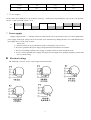
XDM
XD M - 60
User Manual
Shenzhen Zhongzhi Mechatronics Co., Ltd
Read the manual carefully before operating the driver.
1
XDMXDM-60
User Manual
XDM-60, a new constant-current bipolar chopper drive technology, suitable for driving any two-phase or four-phase
hybrid stepping motor. Due to the internal drive to control the use of special techniques, taking into account the electrical
properties of the high-low-frequency (high frequency, the motor running in a state of high-speed torque to increase by
more than 20%; low frequency, the motor running at low speed, the noise reduction, smooth increase) . When to use the
same electrical output than the other drive greater speed and power. Its overall performance leader in China.
1. Features:
high-performance, low price
static, the coil current automatically reduced by
half。
optical signal input isolation
single-supply input +24 VDC-+80 VDC
TTL-compatible input signals
breakdown up to 2,4,8,16,32,64,128,
256,5,10,25,50,250 Times the sub -
Bipolar constant current chopping mode
2. Applications:
This drives a wide range of applications, suitable for a variety of small and medium-sized automation
equipment and instruments, such as: cutting the word machine, CNC machine tools, take place devices, pneumatic
marking machines, labeling machines, laser marking machine, engraving plotter small machine, embroidery
machine and so on, in particular, the user expectations of high-precision, high speed, low vibration, noise of
equipment useful small.
2
3 Driver wiring diagram:
4. Pin definition:
P1 (6bit)
P2 (6bit)
Pin number
Signal
1
2
3
4
5
6
PUL+(+5V)
PUL-(PUL)
DIR+(+5V)
DIR-(DIR)
ENA+(+5V)
ENA-(ENA)
Pin number
1
2
3
4
5
6
3
Signal
GND
V+
A+
AB+
B-
5. Detailed pin functions:
P1 connection port
Pin No.
Signal
Function
1
2
PUL+(+5V)
PUL-(PUL)
Pulse signal: single-pulse control mode for the pulse control signal, when
the pulse rising edge of efficient, double-pulse control is transferred when
the pulse signal, pulse rising edge and effective.
3
DIR+(+5V)
4
DIR-(DIR)
The direction of the signal: single-pulse control mode for the high /
low-level signals, two-pulse control signal for the inversion pulse. Pulse
rising edge and effective. Single / double-pulse control mode set by the
controller to achieve internal jumper JMP row.
5
6
ENA+(+5V)
ENA-(ENA)
En.signal: This input signal is used to enable / disable, enable high, low
When the drive can not work, when not in use can be left vacant.
P2:强电接线端口
Pin No.
Signal
Function
1
GND
DC power supply to
2
+V
Positive DC power supply +24 V-80V can be any value between the
recommended value of about 70V
3, 4
5, 6
A+AB+B-
A motor-phase
Motor phase B
4
6. Breakdown and current settings:
The use of eight of the drive-side DIP switch settings, and its operating mode, the dynamic current, set by the 1-3
position, the fourth set quiescent current, OFF, said half of quiescent current, ON said quiescent current and dynamic
current of the same。
Dynamic current
1
2
Segmentation accuracy
3
4
5
6
7
8
Semi-flow / full flow
(1) sub-set accuracy of the following table:
Sub-multiples
SW5
SW6
SW7
SW8
2
on
on
on
on
4
on
off
on
on
8
on
on
off
on
16
on
off
off
on
32
on
on
on
off
64
on
off
on
off
128
on
on
off
off
256
on
off
off
off
5
off
on
on
on
10
off
off
on
on
25
off
on
off
on
50
off
off
off
on
125
off
on
on
off
250
off
off
on
off
(2) Current settings:
Current value
SW1
SW2
SW3
2A
on
on
on
2.55A
off
on
on
3.14A
on
off
on
3.70A
off
off
on
4.28A
on
on
on
4.84A
off
on
off
5
5.42A
on
off
off
6.0A
off
off
off
(3) For example:
Need a motor drive XDM-60, set up as follows: accuracy = 2000 step-by-step breakdown / lap (10 sub-), the dynamic
current = 4.28A, quiescent current = 2.1A
on
off
1
2
3
4
5
6
7
8
7. Power supply:
Supply voltage DC24V ─ ─ DC80V in between normal work can be, the best drive the use of non-regulated DC
power supply. Peak ripple voltage can not exceed 80V, more than 80V may damage the drive. To avoid fluctuations in
grid voltage drive over the scope of work。
Please note:
1. Connection when not to pay attention to positive and negative power reverse;
2. The power grid when the power supply voltage fluctuations should not exceed 80V;
3. The use of switching regulator power supply, its output current set to the maximum extent;
4 . the use of non-regulated power supply, the supply current output drive capability should be greater than
50% of current setting.
8. Electrical wiring:
The following is a 4-wire, 6 wire, 8 wire stepper motor connection:
6
9. Drive motor and the match:
XDM-60 Can drive any two-phase or four-phase motor drive in order to achieve the best results, it is necessary
to build a reasonable set of supply voltage and current. Because of the high and low voltage power supply decided to
motor speed, set the value of its current decision of the torque stepper motor. In general, the higher the supply voltage,
the greater the torque motor high speed, high-speed when the swap will be able to avoid the step-by-step, but on the
other hand, voltage too high will lead to over-voltage protection, and even has the potential to damage the drive at the
same time, in the high-pressure work, its slow movement too much vibration.
Output current settings: (Note: The current value set after running 10-30 minutes) if the motor temperature is too
high, they should change the current value, to reduce the。
The same motor, the greater the current settings, the greater the motor output torque, but when the current, the drive
motor and a high fever. Therefore, the general situation is that the current supply is set to drive long-term work but
when warm but when the heat values.
A:Four-wire electric motor and six-lane high-speed mode: the output current is set equal to or less than motor
rated current value;
B:High-torque six-phase motor pattern: motor output current set to 70% of rated current;
C:Eight-line electrical connection in series: As the series resistance increases when the output current should be
set to motor rated current of 70%;
D:Eight lines and electrical connection method: output current can be set to motor rated current of 1.5 times.
10 Pulse control mode settings: (the factory for single-pulse mode)
In the internal drive has a jumper Pin JMP1 (Figure 1) single-pulse mode, the jumper placed in row (Figure 2)
double-pulse mode, jumper Pin placed (Figure 3) location.
1
2
3
4
5
6
Figure 1
Figure 2
Figure 3
7
11. Electrical Characteristics: Tj = 28 ℃
XDM-60
Description
Minimum
Typical
Max
Units
Supply voltage
(DC)
24
70
80
V
Output phase
current
2
-
6
A
Logic input current
6
0
10
-
30
10M
mA
KHz
Stepper pulse
frequency
450
Insulation
Resistance
MΩ
12.
12. The use of the environment and parameters:
Cooling method
Use of
environmental
Vibration
0℃──+50℃
45──90% RH
5.9m/s2 Max
Occasions
To avoid dust, oil mist and corrosive gases
Temperature
Humidity
Storage Temperature
Weight
Natural cooling or forced air-cooled
-15℃──+60℃
About 900 grams
13.
13. Mechanical installation size:
L=151MM
W=100MM
8
H=50MM


![Rii Mini-[2.4GHz] User`s Manual Ver:2.0](http://vs1.manualzilla.com/store/data/005760596_1-38a2c6f0785d9724a30239cfe3cd13aa-150x150.png)
![wireless Mini Keyboard-[2.4GHz] User`s Manual Ver:2.1](http://vs1.manualzilla.com/store/data/005666864_1-44f56227f4d883897f7b8660e8efda97-150x150.png)