1
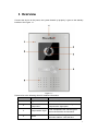
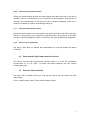
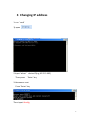
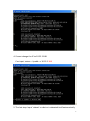
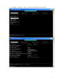
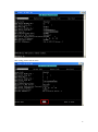
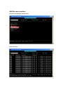
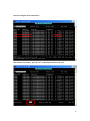
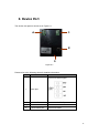
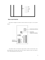
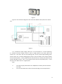
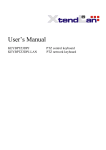
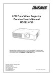
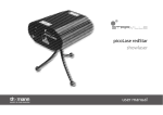
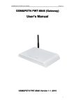
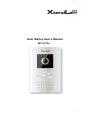
Door Station User’s Manual DPC-IP100 i Table of Contents 1 Overview .................................................................................................................... 1 2 Basic Functions ........................................................................................................... 2 2.1 Call Residents................................................................................................................. 2 2.1.1 Call Status .......................................................................................................... 2 2.1.2 Communication status....................................................................................... 2 2.2 Monitor Function........................................................................................................... 2 2.3 Unlock Function ............................................................................................................. 2 2.3.1 Unlock During the Dial Process.......................................................................... 2 2.3.2 Unlock During the Communication ................................................................... 3 2.3.3 Unlock During the Monitor Status..................................................................... 3 2.3.4 Unlock via ID card (Optional) ............................................................................. 3 2.4 Environment Light Compensation Function .................................................................. 3 2.5 External Alarm Function ................................................................................................ 3 3 Changing IP address ................................................................................................... 4 4 Config the ‘group call funtion’.................................................................................... 6 5 Specifications ........................................................................................................... 11 6 Device Port ............................................................................................................... 13 7 FAQ ........................................................................................................................... 16 i 1 Overview Connect the device to the power, the system booted up properly. It goes to the standby interface. See Figure 1-1. Figure 1-1 Please refer to the following sheet for detailed information. SN Name Function 1 Logo XtendLan LOGO 2 Photosensitive Component It can detect the environment light. It is a compensation light option. 3 Compensation Light It can compensate the camera light in the low illumination environments. 4 Button Call button. Click it to generate a cal to the indoor station. It has the blue 1 backlight. 5 Speaker Audio output 6 Camera It is to monitor the video of the door. 7 Microphone Audio input 2 Basic Functions 2.1 Call Residents 2.1.1 Call Status In the standby status, press the call button. You can generate a call to the resident indoor station. The indoor station bell rings. 2.1.2 Communication status After you generated a call to the indoor station, if there is response, you can go to the communication status. It can realize the dual-way video phone. It returns to the standby interface after the dialogue ended. 2.2 Monitor Function The indoor station can enable the monitor function of this device. You can open the camera and monitor the device video. 2.3 Unlock Function 2.3.1 Unlock During the Dial Process During the dial process, the indoor station can open the e-lock of the device remotely. There is a 15-second for you to confirm the unlock operation. During these 15 seconds, the video is properly displayed. After the 15 seconds countdown, system auto hangs up and returns to the standby interface. 2 2.3.2 Unlock During the Communication During the communication process, the indoor station can open the e-lock of the device remotely. There is a 15-second for you to confirm the unlock operation. During these 15 seconds, the communication is OK and the video is properly displayed. After the 15 seconds countdown, the phone automatically hangs up. 2.3.3 Unlock During the Monitor Status During the monitor status, the indoor station can open the e-lock of the device remotely. There is a 15-second for you to confirm the unlock operation. During these 15 seconds, the video is properly displayed. After the 15 seconds, the video automatically disappears. 2.3.4 Unlock via ID card (Optional) The door is open after you passed the authentication ID card and passed the station verification. 2.4 Environment Light Compensation Function This device has the light compensation function when it is in the low illumination environments or it is at night. It includes the button backlight and the camera compensation light. 2.5 External Alarm Function The device has 1-channel alarm input. They can be used for the door status and other alarm detect. It has 1-channel alarm output. There are two modes: NO/NC. 3 3 Changing IP address 1..run ’ cmd’ 1).open 2.Input ‘telnet ’ device IP(e.g.10.22.5.182) Then press ’ Enter’ key 3.Username: root Press ‘Enter’ key Then input ifconfig 4 4. If want change the IP to 10.22.2.188 Can input: setenv –I ipaddr –c 10.22.2.188 5. The last step: Input ‘reboot’ or device is rebooted itself automatically. 5 4 Config the ‘group call funtion’ 1. cmd:telnet outdoor station IP 2000 username :admin Password:admin 6 2、LAN Config: Group Call :Enable (After choose ‘Enable’, restore the station ) 7 After config, please click the ‘Save’ 8 Add the room number: Choose the ‘VTH Manage’,click the ‘Enter’ Get this interface: 9 Then can config the room number here. After add the new monitor, press the ‘Esc’ on the keyboard,choose the ‘save’ 10 5 Specifications Model DPC-IP100 OS Main Processor Embedded micro processor OS Embedded LINUX OS Video Video Compression Standard H.264 Input/Approaching induction 1/3-inch color CCD camera,540 TVL,0.1lux/F1.2 Night Vision Support Audio Input Microphone Output Built-in speaker Bidirectional Talk Support dual-way bidirectional talk Operation Mode Input One button input(With backlight) Card Built-in ID card induction reader(Optional) Alarm Input 1-channel Output 1-channel Vandal proof Support(Optional) Locker Status Detect Support (Optional) Network Ethernet 10M/100Mbps Self-adaptive Network Protocol TCP/IP Storage Memory 128MB Others Power DC 10~15V Power Consumption Standby≤1W ;work≤10W -10℃~+55℃ Working Environments <10~90%RH Dimensions 230mm*151mm*60mm(L*W*H) Weight 0.96kg 11 12 6 Device Port The device rear panel is shown as in Figure 6-1. 1 4 2 3 Figure 6-1 Please refer to the following sheet for detailed information. SN Port Name Function Connect to alarm signal. 1 Alarm port 2 Network Port Connect to the RJ45 port. 3 Power Port Connect to 12V DC. 4 E-lock control port Connect to cable 13 Door Lock Control Door phone is designed to be able to control the door lock. Figure 1 is its rear panel diagram. Figure 1 The interface “12DC” is for the power supply interface; “RJ45” for network cable; “door lock interface area” for electric lock. This user’s manual is based on electric lock. Figure 2 is the outward appearance of the electric lock. 14 Figure 2 Figure-3 is the connection diagram of the connection between door phone and electric lock. Figure 3 It is a transformer power supply, 220V AC is to be connected to L and N respectively to transform and then output 12 DC in order to supply power for the door phone and electric lock. The electric lock has four binding posts, two are power-supply binding posts, and the other two are unlock binding posts. There are four terminals in the unlock interface area of the door phone, namely, COM terminal, NC (electricity-on unlock), NO (electricity-off unlock) and GND. Connect the L+ of the electric lock to the DC 12V positive pole; L- to the NO; then the COM to DC 12V negative pole. Note: 1. 2. The power-supply cable RVV2*1.0 is adopted for the door phone and electric lock both. User can select either NC or NO to connect according to actual requirements. 15 7 FAQ Q:I can not boot up the device, or I can not see the light or hear the audio. A: Please check your power cable connection and socket connection. Q: I can not call. A: Please check your network connection. Please make sure your station and extension cable connection is OK. Q:The prompt says the dial number does not exist. What shall I do? A:Please check the dial number is OK or not. Q:The system says the card is invalid. What shall I do? A:The card status is abnormal. Please contact your administrator to check. Q: The system says the card number is wrong. What shall I do? A : It means current card does not authenticate. Please contact your administrator to check. Q: I have some problems, I am not so sure or I can not fix. A:Please contact your local retailer for help. 16 Note: This manual is for reference only. Slight difference may be found in user interface. All the designs and software here are subject to change without prior written notice. If there is any uncertainty or controversy, please refer to the final explanation of us. Please visit our website or contact your local service engineer for more information. 17