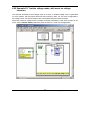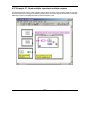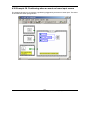
1
TML_LIB_LabVIEW v2.0 Motion Control Library for Technosoft Intelligent Drives User Manual © Technosoft 2007 TECHNOSOFT TML_LIB_LabVIEW v2.0 User Manual P091.040.LABVIEW.v20.UM.0507 Technosoft S.A. Rue de Buchaux 38 CH-2022 BEVAIX Switzerland Tel.: +41 (0) 32 732 5500 Fax: +41 (0) 32 732 5504 [email protected] www.technosoftmotion.com/ Read This First Whilst Technosoft believes that the information and guidance given in this manual is correct, all parties must rely upon their own skill and judgment when making use of it. Technosoft does not assume any liability to anyone for any loss or damage caused by any error or omission in the work, whether such error or omission is the result of negligence or any other cause. Any and all such liability is disclaimed. All rights reserved. No part or parts of this document may be reproduced or transmitted in any form or by any means, electrical or mechanical including photocopying, recording or by any information-retrieval system without permission in writing from Technosoft S.A. About This Manual This book describes the motion library TML_LIB_LabVIEW v2.0. TML_LIB_LabVIEW is a collection of functions, which can be integrated in a PC application developed in LabVIEW environment. With TML_LIB_LabVIEW motion library, you can quickly program the desired motion and control the Technosoft intelligent drives and motors (with the drive integrated in the motor case) from a PC. The TML_LIB_LabVIEW allows you to communicate with Technosoft drive/motors via serial RS-232, RS-485, CAN-bus or Ethernet protocols. Scope of This Manual This manual applies to the following Technosoft intelligent drives and motors: • IDM240 / IDM640 (models IDM240-5EI, IDM240-5LI, IDM640-8EI and IDM640-8LI), with firmware F000H or later (revision letter must be equal or after H i.e. I, J, etc.) • IDM240 CANopen/ IDM640 CANopen (models IDM240-5EI CANopen, IDM240-5LI CANopen, IDM640-8EI CANopen and IDM640-8LI CANopen) with firmware version F500A. • IDS240 / IDS640 (all models), with firmware F000H or later • IDS640 CANopen with firmware F500A or later • ISCM4805 / ISCM8005 (all models), with firmware F000H or later • IBL2403 (all models), with firmware F020H or later • IPS110 (all models), with firmware F005H or later • IM23x (models IS and MA), with firmware F900H or later IMPORTANT! For correct operation, these drives/motors must be programmed with firmware revision H. EasySetUp 1 - Technosoft IDE for drives/motors setup, includes a firmware 1 EasySetUp is included in TML_LIB_LabVIEW installation package as a component of EasyMotion Studio Demo version. It can also be downloaded free of charge from Technosoft web page © Technosoft 2007 III TML_LIB_LabVIEW – User Manual programmer with which you can check your drive/motor firmware version and revision and if needed, update your drive/motor firmware to revision H. Notational Conventions This document uses the following conventions: Drive/motor - an intelligent drive or an intelligent motor having the drive part integrated in the motor case TML – Technosoft Motion Language IU – drive/motor internal units ACR.5 – bit 5 of ACR data FAxx – firmware versions F000H, F020H, F005H, F900H or later FBxx – firmware versions F500A or later Related Documentation Help of the EasyMotion Studio software platform – describes how to use the EasyMotion Studio, which support all new features added to revision H of firmware. It includes: motion system setup & tuning wizard, motion sequence programming wizard, testing and debugging tools like: data logging, watch, control panels, on-line viewers of TML registers, parameters and variables, etc. TML_LIB v2.0 User Manual (part no. P091.040.UM.xxxx) describes in detail the TML_LIB Technosoft Motion Language Library and how to use it to program motion applications in Visual C++, Visual Basic or Delphi environments. MotionChip™ II TML Programming (part no. P091.055.MCII.TML.UM.xxxx) describes in detail TML basic concepts, motion programming, functional description of TML instructions for high level or low level motion programming, communication channels and protocols. Also give a detailed description of each TML instruction including syntax, binary code and examples. MotionChip II Configuration Setup (part no. P091.055.MCII.STP.UM.xxxx) describes the MotionChip II operation and how to setup its registers and parameters starting from the user application data. This is a technical reference manual for all the MotionChip II registers, parameters and variables. © Technosoft 2007 IV TML_LIB_LabVIEW – User Manual If you Need Assistance … If you want to … Contact Technosoft at … Visit Technosoft online World Wide Web: http://www.technosoftmotion.com/ Receive general information or assistance World Wide Web: http://www.technosoftmotion.com/ Email: [email protected] Ask questions about product operation or report suspected problems Fax: (41) 32 732 55 04 Email: [email protected] Make suggestions about or report errors in documentation © Technosoft 2007 V TML_LIB_LabVIEW – User Manual Contents 1 Introduction ............................................................................................................................. 1 2 Getting started......................................................................................................................... 3 2.1 Hardware installation ......................................................................................................... 3 2.2 Software installation........................................................................................................... 3 2.2.1 Installing EasySetUp................................................................................................... 3 2.2.2 3 Installing TML_LIB_LabVIEW library.......................................................................... 3 2.3 Drive/motor setup............................................................................................................... 4 2.4 Build an application with TML_LIB_LabVIEW ................................................................... 5 TML_LIB_LabVIEW description............................................................................................. 7 3.1 Basic concept..................................................................................................................... 7 3.2 Internal units and scaling factors ....................................................................................... 8 3.3 Axis Identification ............................................................................................................... 8 3.4 Functions descriptions ....................................................................................................... 9 3.4.1 Motion programming................................................................................................. 10 3.4.1.1 TS_MoveAbsolute.vi ......................................................................................... 10 3.4.1.2 TS_MoveRelative.vi........................................................................................... 12 3.4.1.3 TS_MoveSCurveAbsolute.vi ............................................................................. 14 3.4.1.4 TS_MoveSCurveRelative.vi .............................................................................. 16 3.4.1.5 TS_MoveVelocity. vi .......................................................................................... 18 3.4.1.6 TS_SetAnalogueMoveExternal.vi...................................................................... 20 3.4.1.7 TS_SetDigitalMoveExternal .............................................................................. 22 3.4.1.8 TS_SetOnlineMoveExternal.vi .......................................................................... 23 3.4.1.9 TS_VoltageTestMode.vi .................................................................................... 25 3.4.1.10 TS_TorqueTestMode.vi..................................................................................... 26 3.4.1.11 TS_PVTSetup.vi ................................................................................................ 27 3.4.1.12 TS_SendPVTFirstPoint.vi.................................................................................. 29 3.4.1.13 TS_SendPVTPoint.vi......................................................................................... 31 3.4.1.14 TS_PTSetup.vi .................................................................................................. 32 3.4.1.15 TS_SendPTFirstPoint.vi .................................................................................... 34 3.4.1.16 TS_SendPTPoint.vi ........................................................................................... 35 3.4.1.17 TS_SetGearingMaster.vi ................................................................................... 36 3.4.1.18 TS_SetGearingSlave.vi ..................................................................................... 37 3.4.1.19 TS_SetCammingMaster.vi ................................................................................ 39 3.4.1.20 TS_SetCammingSlaveRelative.vi ..................................................................... 40 © Technosoft 2007 VII TML_LIB_LabVIEW – User Manual 3.4.1.21 TS_SetCammingSlaveAbsolute.vi .................................................................... 42 3.4.1.22 TS_CamDownload.vi......................................................................................... 44 3.4.1.23 TS_CamInitialization.vi ...................................................................................... 46 3.4.1.24 TS_SetMasterResolution .................................................................................. 47 3.4.1.25 TS_SendSynchronization.................................................................................. 48 3.4.2 Motor commands ...................................................................................................... 49 3.4.2.1 TS_Power.vi ...................................................................................................... 49 3.4.2.2 TS_UpdateImmediate.vi.................................................................................... 50 3.4.2.3 TS_UpdateOnEvent.vi....................................................................................... 51 3.4.2.4 TS_Stop.vi ......................................................................................................... 52 3.4.2.5 TS_SetPosition.vi .............................................................................................. 53 3.4.2.6 TS_SetTargetPositionToActual.vi ..................................................................... 54 3.4.2.7 TS_SetCurrent.vi ............................................................................................... 55 3.4.2.8 TS_QuickStopDecelerationRate.vi.................................................................... 56 3.4.3 Events ....................................................................................................................... 57 3.4.3.1 TS_CheckEvent.vi ............................................................................................. 57 3.4.3.2 TS_SetEventOnMotionComplete.vi................................................................... 58 3.4.3.3 TS_SetEventOnMotorPosition.vi....................................................................... 60 3.4.3.4 TS_SetEventOnLoadPosition.vi ........................................................................ 61 3.4.3.5 TS_SetEventOnMotorSpeed.vi ......................................................................... 62 3.4.3.6 TS_SetEventOnLoadSpeed.vi .......................................................................... 63 3.4.3.7 TS_SetEventOnTime.vi ..................................................................................... 64 3.4.3.8 TS_SetEventOnPositionRef.vi .......................................................................... 65 3.4.3.9 TS_SetEventOnSpeedRef.vi............................................................................. 66 3.4.3.10 TS_SetEventOnTorqueRef.vi............................................................................ 67 3.4.3.11 TS_SetEventOnEncoderIndex.vi....................................................................... 68 3.4.3.12 TS_SetEventOnLimitSwitch.vi........................................................................... 69 3.4.3.13 TS_SetEventOnDigitalInput.vi........................................................................... 70 3.4.3.14 TS_SetEventOnHomeInput.vi ........................................................................... 71 3.4.4 TML jumps and function calls ................................................................................... 72 3.4.4.1 TS_GOTO.vi...................................................................................................... 72 3.4.4.2 TS_GOTO_Label.vi ........................................................................................... 73 3.4.4.3 TS_CALL.vi ....................................................................................................... 74 3.4.4.4 TS_CALL_Label.vi............................................................................................. 75 3.4.4.5 TS_CancelableCALL.vi ..................................................................................... 76 3.4.4.6 TS_CancelableCALL_Label.vi .......................................................................... 77 3.4.4.7 TS_ABORT.vi .................................................................................................... 78 3.4.5 IO handling ............................................................................................................... 79 3.4.5.1 TS_SetupInput.vi ............................................................................................... 79 3.4.5.2 TS_GetInput.vi................................................................................................... 80 3.4.5.3 TS_SetupOutput.vi ............................................................................................ 81 3.4.5.4 TS_SetOutput.vi ................................................................................................ 82 3.4.5.5 TS_GetHomeInput.vi ......................................................................................... 83 3.4.5.6 TS_GetMultipleInputs.vi .................................................................................... 84 3.4.5.7 TS_SetMultipleOutputs.vi.................................................................................. 85 3.4.5.8 TS_SetMultipleOutputs2.vi................................................................................ 86 3.4.6 Data transfer ............................................................................................................. 87 © Technosoft 2007 VIII TML_LIB_LabVIEW – User Manual 3.4.6.1 TS_SetIntVariable.vi.......................................................................................... 87 3.4.6.2 TS_GetIntVariable.vi ......................................................................................... 88 3.4.6.3 TS_SetLongVariable.vi...................................................................................... 89 3.4.6.4 TS_GetLongVariable.vi ..................................................................................... 90 3.4.6.5 TS_SetFixedVariable.vi..................................................................................... 91 3.4.6.6 TS_GetFixedVariable.vi .................................................................................... 92 3.4.6.7 TS_SetBuffer.vi ................................................................................................. 93 3.4.6.8 TS_GetBuffer.vi ................................................................................................. 94 3.4.7 Drive/motor monitoring ............................................................................................. 95 3.4.7.1 TS_ReadStatus.vi.............................................................................................. 95 3.4.7.2 TS_OnlineChecksum.vi..................................................................................... 96 3.4.8 Miscellaneous ........................................................................................................... 97 3.4.8.1 TS_DownloadProgram ...................................................................................... 97 3.4.8.2 TS_Execute.vi ................................................................................................... 98 3.4.8.3 TS_ExecuteScript.vi .......................................................................................... 99 3.4.8.4 TS_GetOutputOfExecute.vi............................................................................. 100 3.4.8.5 TS_Save.vi ...................................................................................................... 101 3.4.8.6 TS_ResetFault.vi ............................................................................................. 102 3.4.8.7 TS_Reset.vi ..................................................................................................... 103 3.4.8.8 TS_GetLastErrorText.vi................................................................................... 104 3.4.9 Data logger ............................................................................................................. 105 3.4.9.1 TS_SetupLogger.vi.......................................................................................... 105 3.4.9.2 TS_StartLogger.vi............................................................................................ 106 3.4.9.3 TS_CheckLoggerStatus.vi............................................................................... 107 3.4.9.4 TS_UploadLoggerResults.vi............................................................................ 108 3.4.10 Drive setup.............................................................................................................. 110 3.4.10.1 TS_LoadSetup.vi ............................................................................................. 110 3.4.10.2 TS_SetupAxis.vi .............................................................................................. 111 3.4.10.3 TS_SetupGroup.vi ........................................................................................... 112 3.4.10.4 TS_SetupBroadcast ........................................................................................ 113 3.4.10.5 TS_DriveInitialization.vi ................................................................................... 114 3.4.11 Drive administration ................................................................................................ 115 3.4.11.1 TS_SelectAxis.vi.............................................................................................. 115 3.4.11.2 TS_SelectGroup.vi .......................................................................................... 116 3.4.11.3 TS_SelectBroadcast.vi .................................................................................... 117 3.4.12 Communication setup............................................................................................. 118 3.4.12.1 TS_OpenChannel.vi ........................................................................................ 118 3.4.12.2 TS_SelectChannel.vi....................................................................................... 120 3.4.12.3 TS_CloseChannel.vi........................................................................................ 121 4 Examples ............................................................................................................................. 122 4.1 Example 1. Profiled positioning movement followed by a speed profile jogging........... 125 4.2 Example 2. Positioning movement; wait a while; speed jogging; stop after a time period 127 4.3 Example 3. Speed profile with two acceleration values ................................................ 129 © Technosoft 2007 IX TML_LIB_LabVIEW – User Manual 4.4 Example 4. Speed jogging; wait a time period; positioning movement ......................... 131 4.5 Example 5. Speed jogging; wait for an input port to be triggered; positioning movement 133 4.6 Example 6. Absolute position motion profile with different acceleration / deceleration rate 135 4.7 Example 7. Positioning movement; speed jogging; wait a time period, then stop ........ 137 4.8 Example 8. Repeat a motion at input port set, with current reduction between motions 139 4.9 Example 9. Move to the positive limit switch, reverse to the negative limit switch ........ 141 4.10 Example 10. Move between limit switches until an input port changes its status...... 143 4.11 Example 11. Move forward and backward at 2 different speeds, for a given distance 145 4.12 Example 12. Speed profile, followed by profiled positioning at a given speed .......... 147 4.13 Example 13. Speed control with external reference .................................................. 149 4.14 Example 14. Profiled positioning, with output port status changing at a given position 151 4.15 Example 15. Execute a jogging speed motion, until the home input is captured ...... 153 4.16 Example 16. Different motions based on the status of two digital inputs of the drive 155 4.17 Example 17. Move between limit switches. Power-off if blocked on a limit switch .... 157 4.18 Example 18. Jog at a speed computed from an A/D signal, until a digital input is reset 159 4.19 Example 19. Speed control, with drive interrogation / setup of TML speed parameters 161 4.20 Example 20. Setup positioning motion, using tables stored into drive memory ........ 163 4.21 Example 21. Setting the Digital External motion mode.............................................. 165 4.22 Example 22. Test the voltage mode, with event on voltage reference ...................... 167 4.23 Example 23. Test torque mode, with event on torque reference ............................... 169 4.24 Example 24. Profiled positioning and speed movement, with event test from PC side 171 4.25 Example 25. Movement as defined in an external file containing TML source code. 173 4.26 Example 26. Positioning command to a group of axes.............................................. 175 4.27 Example 27. Jogging motion until the index capture is detected, then position on index 177 4.28 zero Example 28. Speed jogging until home found, position to home, and set position to 179 4.29 Example 29. Download a COFF format file & send a positioning command on-line . 181 © Technosoft 2007 X TML_LIB_LabVIEW – User Manual 4.30 Example 30. Download a COFF format file, then call TML functions ........................ 183 4.31 mode Example 31. Set up the Master and Slave Gearing Mode; use the drives in gearing 185 4.32 mode Example 32. Set up Master and Slave in electronic cam Mode; use the drives in cam 187 4.33 Example 33. Usage of data logger to upload real-time stored data from the drive ... 189 4.34 Example 34. Homing procedures based on pre-stored TML sequences on the drive 191 4.35 Example 35. Positioning with S-Curve profile for speed; speed jogging ................... 194 4.36 Example 36. Reset FAULT state................................................................................ 196 4.37 Example 37. Read multiple inputs/set multiple outputs ............................................. 198 4.38 Example 38. Positioning when an event on home input occurs ................................ 200 4.39 Example 39. Write/read in the drive memory............................................................. 202 4.40 Example 40. View binary code of a TML command................................................... 204 4.41 Example 41. Speed jog and positioning with direction change.................................. 205 © Technosoft 2007 XI TML_LIB_LabVIEW – User Manual 1 Introduction The programming of Technosoft intelligent drives/motors involves 2 steps: 1) Drive/motor setup 2) Motion programming For Step 1 – drive/motor setup, Technosoft provides EasySetUp. EasySetUp is an integrated development environment for the setup of Technosoft drives/motors. The output of EasySetUp is a set of setup data, which can be downloaded to the drive/motor EEPROM or saved on your PC for later use. The setup data is copied at power-on into the RAM memory of the drive/motor and is used during runtime. The reciprocal is also possible i.e. to retrieve the complete setup data from a drive/motor EEPROM previously programmed. EasySetUp can be downloaded free of charge from Technosoft web page. It is also provided on the TML_LIB_LabVIEW installation CD. For Step 2 – motion programming, Technosoft offers multiple options, like: 1) Use the drives/motors embedded motion controller and do the motion programming in Technosoft Motion Language (TML). For this operation Technosoft provides EasyMotion Studio, an IDE for both drives setup and motion programming. The output of EasyMotion Studio is a set of setup data and a TML program to download and execute on the drive/motor. 2) Use a .DLL with high-level motion functions which can be integrated in a host application written in C/C++, Delphi Pascal, Visual Basic or LabVIEW 3) Use a PLCopen compatible library with motion function blocks which can be integrated in a PLC application based on one of the IEC 61136 standard languages 4) Combine option 1) with options 2) or 3) to really distribute the intelligence between the master/host and the drives/motors in complex multi-axis applications. Thus, instead of trying to command each step of an axis movement, you can program the drives/motors using TML to execute complex tasks and inform the master when these are done. TML_LIB_LabVIEW is part of option 2) – a collection of functions allowing you to implement motion control applications on a PC computer. The link between the Technosoft drives/motors and the PC can be done via serial link, via CAN-bus using a CAN interface or via Ethernet using an adapter/bridge between Ethernet and RS-232. Realized as a collection of high-level functions, the library allows you to focus on the main aspects related to your application specific implementation, and to simply use the drive and execute motion commands by calling appropriate functions from the library. This manual presents how to install and use the components of the TML_LIB_LabVIEW library version 2.0. Remarks: • • Option 4) requires using EasyMotion Studio instead of EasySetUp. With EasyMotion Studio you can create high-level motion functions in TML, to be called from your PC EasyMotion Studio is also recommended if your application includes a homing as it comes with 32 predefined homing procedures to select from, with possibility to adapt them © Technosoft 2007 1 TML_LIB_LabVIEW – User Manual MyExample.vi TML_LIB … TS_MoveVelocity (…) … CSPD=12.5; MODE SP; UPD; Communication channel Figure 1.1. Using TML_LIB_LabVIEW to control a Technosoft intelligent drive from the PC computer © Technosoft 2007 2 TML_LIB_LabVIEW – User Manual 2 Getting started 2.1 Hardware installation For the hardware installation of the Technosoft drives/motors see their user manual. For drives/motors setup, you can connect your PC to any drive/motor using an RS232 serial link. Through this serial link you can access all the drives/motors from the network. Alternately, you can connect your PC directly on the CAN bus network if it is equipped with one of the CAN interfaces supported by EasySetUp. 2.2 Software installation In order to perform successfully the following software installations, make sure that you have the “Administrator” rights. 2.2.1 Installing EasySetUp On the TML_LIB_LabVIEW installation CD you’ll find the setup for EasyMotion Studio Demo version. This application includes a fully functional version of EasySetUp and a demo version of EasyMotion Studio. Start the setup and follow the installation instructions. 2.2.2 Installing TML_LIB_LabVIEW library Start the TML_LIB_LabVIEW setup and follow the installation instructions. After library installation open the LabVIEW environment and add in the list VI Search Path, the installation path of the library, by default C:\Program Files\Technosoft\TML_LIB_LabVIEW..Table 2.1 details the package contents. Table 2.1 TML_LIB_LabVIEW package contents Directory Root directory Files TML_lib.dll TMLcomm.dll P091.040.UM.xxxx.PDF Examples Files Ex25TML.txt Ex29RAM.out Ex30.out Ex32_MyCam.cam Ex32_MyCam.txt Examples Example diagrams Functions VI functions GlobalVIs sub VIs variables Setups Setup data directories © Technosoft 2007 with global 3 Description TML_LIB DLL library file TML communication DLL file The PDF file of the TML_LIB user manual (this document) TML source file for Example 25 COFF file for Example 29 COFF file for Example 30 A cam file for example 32, in Technosoft cam file format A cam file for example 32, in text file format A complete Visual C project implementing the examples from Chapter 4. Contains the sub VIs of the library which implement the functions from TML_LIB.dll Sub VIs containing the declaration of global variables used in examples Sample setup data of the drives used in examples. For your configurations generate the setup data (see paragraph 2.3) TML_LIB_LabVIEW – User Manual 2.3 Drive/motor setup Before starting to send motion commands from the PC, you need to do the drive/motor setup according with your application needs. For this operation you’ll use EasySetUp. EasySetUp is an integrated development environment for the setup of Technosoft drives and motors (with the drive integrated in the motor case). The output of EasySetUp is a set of setup data, which can be downloaded to the drive/motor EEPROM or saved on your PC for later use. A setup contains all the information needed to configure and parameterize a Technosoft drive/motor. This information is preserved in the drive/motor EEPROM in the setup table. The setup table is copied at power-on into the RAM memory of the drive/motor and is used during runtime. The reciprocal is also possible i.e. to retrieve the complete setup data from a drive/motor EEPROM previously programmed Steps to follow for commissioning a Technosoft drive/motor Step 1. Start EasySetUp From Windows Start menu execute: “Start | Programs | EasySetUp | EasySetUp” or “Start | Programs | EasyMotion Studio | EasySetUp” depending on which installation package you have used. Step 2. Establish communication EasySetUp starts with an empty window from where you can create a New setup, Open a previously created setup which was saved on your PC, or Upload the setup from the drive/motor. Before selection one of the above options, you need to establish the communication with the drive/motor you want to commission. Use menu command Communication | Setup to check/change your PC communication settings. Press the Help button of the dialogue opened. Here you can find detailed information about how to setup your drive/motor and do the connections. Power on the drive/motor and then close the Communication | Setup dialogue with OK. If the communication is established, EasySetUp displays in the status bar (the bottom line) the text “Online” plus the axis ID of your drive/motor and its firmware version. Otherwise the text displayed is “Offline” and a communication error message tells you the error type. In this case, return to the Communication | Setup dialogue, press the Help button and check troubleshoots. Remark: When first started, EasySetUp tries to communicate with your drive/motor via RS-232 and COM1 (default communication settings). If your drive/motor is powered and connected to your PC port COM1 via an RS-232 cable, the communication can be automatically established. Step 3. Setup drive/motor Press New button and select your drive/motor type. Depending on the product chosen, the selection may continue with the motor technology (for example: brushless motor, brushed motor) or the control mode (for example stepper – open-loop or stepper – closed-loop) and type of feedback device (for example: incremental encoder, SSI encoder) This opens 2 setup dialogues: for Motor Setup and for Drive setup through which you can configure and parameterize a Technosoft drive/motor, plus several predefined control panels customized for the product selected. In the Motor setup dialogue you can introduce the data of your motor and the associated sensors. Data introduction is accompanied by a series of tests having as goal to check the © Technosoft 2007 4 TML_LIB_LabVIEW – User Manual connections to the drive and/or to determine or validate a part of the motor and sensors parameters. In the Drive setup dialogue you can configure and parameterize the drive for your application. In each dialogue you will find a Guideline Assistant, which will guide you through the whole process of introducing and/or checking your data. Close the Drive setup dialogue with OK to keep all the changes regarding the motor and the drive setup. Step 4. Download setup data to drive/motor Press the Download to Drive/Motor button to download your setup data in the drive/motor EEPROM memory in the setup table. From now on, at each power-on, the setup data is copied into the drive/motor RAM memory that is used during runtime. It is also possible to Save the setup data on your PC and use it in other applications. Step 5. Reset the drive/motor to activate the setup data Step 6. Create the setup data for TML_LIB_LabVIEW. The TML_LIB_LabVIEW requires drive/motor setup information for proper execution of the application. The setup data is generated with the Setup | Export to TML_LIB… command if you are in EasySetUp, or the Application | Export to TML_LIB… command if you are using EasyMotion Studio. The information is generated in the form of an archive file with the .t.zip extension and is saved in the Archives folder from EasySetUp/EasyMotion Studio installation folder (by default C:\Program Files\Technosoft\ESM\). 2.4 Build an application with TML_LIB_LabVIEW The library TML_LIB_LabVIEW is a collection of high level functions, grouped in several categories and provided as the TML_LIB.dll file. To simplify the functions usage, each function has a subVi associated. Most of these subVIs are of Boolean type, and return a ‘True’ value if the execution of the function is performed without any error (at PC level). If the function returns a ‘False’ value, you can interrogate the error type by calling the function TS_GetLastErrorText.vi. Steps to build an application with TML_LIB_LabView: 1. Create a new VI. Launch LabVIEW and press the button New VI. For details read the LabView online help. 2. Setup the communication. The application developed is based on the communication between PC and Technosoft drives/motors thus it should begin with the communication channel setup. The communication channel is opened with the TS_OpenChannel.vi subVI. At the end of the application you must close the communication channel with subVI TS_CloseChannel.vi. 3. Load setup configurations. The setup information is required by the library functions in order to check if there are incompatibilities between the drive and the operation to be executed (as an example, avoiding issuing an “Output port” command to a port which is an input port on that drive). EasySetUp/EasyMotion Studio generates the setup information in the form of an archive file with the .t.zip extension. The archives are saved in the Archives folder from EasyMotion Studio/ EasySetUp installation folder. The drive’s/motor’s setup data are declared in the PC application with function TS_LoadSetup.vi. The subVI must be called for each configuration setup used. © Technosoft 2007 5 TML_LIB_LabVIEW – User Manual 4. Setup axes. Each axis defined at PC level requires the setup information. The configuration setup is associated to an axis with subVI TS_SetupAxis.vi. 5. Select the active axis/group. The messages sent from the PC address to one axis. Use subVI TS_SelectAxis.vi to choose the messages destination. All further function calls, which send TML messages on the communication channel, will address the messages to this active axis. 6. Program the motion for current axis. Use the TML_LIB_LabVIEW functions to program the motions required. © Technosoft 2007 6 TML_LIB_LabVIEW – User Manual 3 TML_LIB_LabVIEW description 3.1 Basic concept The Technosoft intelligent drives are programmable using the Technosoft Motion Language (TML). TML consists of a high-level set of codes allowing the user to parameterize and execute specific motion operations. TML allows to: • • • • • • Configure the motion mode (profiles, contouring, gearing in multiple axes structures, etc.) Detect / specifically treat external signals as limit switches, captures Execute homing sequences Setup / start specific action on pre-defined motion events Synchronize multiple axes structures, by sending group commands etc. The TML_LIB_LabVIEW library is the tool that helps you to handle the process of motion control application implementation on a PC computer, at a high level, without the need to write / compile TML code. A central element of the library is the communication kernel, which is responsible of correct opening of the communication channel (serial RS-232 or RS-485, CAN-bus or Ethernet), as well as of TML messages handling. This includes handling of the specific communication protocol, for each of these channels. Consequently, each application you’ll develop starts with the opening of the communication, i.e. calling the TS_OpenChannel.vi subVI. The application must end with the TS_CloseChannel.vi subVI execution. You’ll be able to handle multiple-axis applications from the PC. Besides the drive/motor setup with EasySetUp or EasyMotion Studio, you’ll also need to indicate some basic drive information for correct usage of the library functions. Thus, for each drive that is installed in the system, you’ll need to execute the TS_SetupAxis.vi subVI, indicating the axis ID and configuration setup. Such information will be used for some functions of the library, in order to check if there are incompatibilities between the drive and the operation to be executed (as an example, avoiding issuing an “Output port” command to a port which is an input port on that drive). Note that besides setting-up individual axes, it is also possible to setup groups of axes (with the TS_SetupGroup.vi subVI). This will allow you to issue commands, which will be received and executed simultaneously on all the axes initialized as belonging to that group. Once all the axes are defined, the library allows you to select the so-called ‘active axis or group’, using the TS_SelectAxis, or TS_SelectGroup subVI respectively. Consequently, all future commands that you’ll execute after the selection of one axis or group will be addressed to that axis or group. You can change at any time in your program the active axis/group. © Technosoft 2007 7 TML_LIB_LabVIEW – User Manual 3.2 Internal units and scaling factors Technosoft drives/motors work with parameters and variables represented in internal units (IU). The parameters and variables may represent various signals: position, speed, current, voltage, etc. Each type of signal has its own internal representation in IU and a specific scaling factor. In order to easily identify each type of IU, these have been named after the associated signals. For example the position units are the internal units for position, the speed units are the internal units for speed, etc. The scaling factor of each internal unit shows the correspondence with the international standard units (SI). The scaling factors are dependent on the product, motor and sensor type. Put in other words, the scaling factors depend on the setup configuration. In order to find the internal units and the scaling factors for a specific configuration, use: • • Help | Help Topics | Setup Data Management | Internal Units and Scaling Factors menu command in EasySetUp Help | Help Topics | Application Programming Internal Units and Scaling Factors menu command in EasyMotion Studio Important: The Internal Units and Scaling Factors topic provides customized information, function of the application setup. If you change the drive, the motor technology or the feedback device, check again the scaling factors with this command. It may show you other relations! 3.3 Axis Identification The data exchanged on the communication channel is done using messages. Each message contains one TML instruction to be executed by the receiver of the message. Apart from the binary code of the TML instruction attached, any message includes information about its destination: an axis (drive/motor) or group of axes. This information is grouped in the Axis/Group ID Code. Each drive/motor has its own 8-bit Axis ID and Group ID. Remarks: 1. The Axis ID of a drive/motor must be unique and is set during the drive/motor setup phase with EasySetUp. 2. The Axis ID and Group ID of a drive/motor are stored in TML variable AAR. Use TS_GetIntVariable.vi to read the value of the Axis ID and Group ID. The Group ID represents a way to identify a group of axes, for a multicast transmission. This feature allows to send a command simultaneously to several axes, for example to start or stop the axes motion in the same time. When a function block sends a command to a group, all the axes members of this group will receive the command. For example, if the axis is member of group 1 and group 3, it will receive all the messages that in the group ID include group 1 and group 3. Remark: A drive/motor belongs, by default, to the group ID = 1. Each axis can be programmed to be member of one or several of the 8 possible groups. © Technosoft 2007 8 TML_LIB_LabVIEW – User Manual Table 3.1Definition of the groups Group No. 1 2 3 4 5 6 7 8 Group ID value 1 ( 0000 0001b ) 2 ( 0000 0010b ) 4 ( 0000 0100b ) 8 ( 0000 1000b ) 16 ( 0001 0000b ) 32 ( 0010 0000b ) 64 ( 0100 0000b ) 128 (1000 0000b ) 3.4 Functions descriptions The section presents the functions implemented in the TML_LIB_LabVIEW library. The functions are classified as follows: • • • • • • • • • • • • Motion programming – functions for motion programming on the selected axis. Motor commands – functions to enable/disable the motor power stage, start/stop the motion, change the value of the motor position and current Events – functions for events programming and test TML jumps and function calls – functions which allows you to execute code downloaded in the drive/motor memory I/O handling – functions for read/write operations with drive/motor I/O ports Data transfer – functions for read/write operations from/to the drive/motor memory Drive/motor monitoring – functions for monitoring the drive/motor status Miscellaneous – functions for FAULT state reset and drive reset Data logger – functions for logger setup and data upload Drive setup – functions for axis setup in the PC application Drive administration – functions that control the destination axis of the message sent via communication channels Communication setup – functions that manage the PC communication channel For each function you will find the following information: • • • • • • The subVi symbol The function C prototype SubVI parameters description A functional description Name of the related subVIs Examples reference. The examples that illustrate the correct use of the functions (subVIs) are listed in chapter 4. © Technosoft 2007 9 TML_LIB_LabVIEW – User Manual 3.4.1 Motion programming 3.4.1.1 TS_MoveAbsolute.vi Symbol: Prototype: LONG _TS_MoveAbsolute@28(LONG Position, DOUBLE Speed, DOUBLE Acceleration, SHORT INT Move Moment, SHORT INT Reference Base); Parameters: Name Position Speed Input Acceleration Move Moment Reference Base Output return Description Position to reached expressed in drive/motor position units Slew speed expressed in TML speed units. If the value is zero the drive/motor will use the previously value set for speed Acceleration/deceleration rate expressed in TML acceleration units. If its value is zero the drive/motor will use the previously value set for acceleration Defines the moment when the motion is started Specifies how the motion reference is computed: from actual values of position and speed reference or from actual values of load/motor position and speed TRUE if no error, FALSE if error Description: The function programs an absolute positioning with trapezoidal speed profile. The motion is described through Position parameter for position to reach, Speed for slew speed and Acceleration for acceleration/deceleration rate. The position to reach can be positive or negative. The Speed and Acceleration can be only positive. Once set, the motion parameters are memorized on the drive/motor. If you intend to use values previously defined for the acceleration rate and/or the velocity you don’t need to send their values again in the following trapezoidal profiles. Set to zero the value of speed and/or acceleration and the drive/motor will use the values previously defined (this option reduces the TML code generated by this function). The motion is executed: • • • Immediately when Move Moment = UPDATE_IMMEDIATE When a programmed event occurs if Move Moment = UPDATE_ON_EVENT If you select Move Moment = UPDATE_NONE, the movement is parameterized, but does not execute. You’ll need to issue an update command to determine the execution of the movement. Use the TS_UpdateImmediate.vi or the TS_UpdateOnEvent.vi functions in order to activate the movement. Set Reference Base = FROM_REFERENCE if you want the reference generator to compute the motion profile starting from the actual values of the position and speed reference. Set Reference © Technosoft 2007 10 TML_LIB_LabVIEW – User Manual Base = FROM_MEASURE if you want the reference generator to compute the motion profile starting from the actual values of the load/motor position and speed. When this option is used, at the beginning of each new motion profile, the position and speed reference are updated with the actual values of the load/motor position and speed. Remark: In open loop control of steppers, this option is ignored because there is no position and/or speed feedback. Related functions: TS_MoveRelative.vi, TS_MoveSCurveAbsolute.vi, TS_MoveSCurveRelative.vi, TS_MoveVelocity.vi Associated examples: © Technosoft 2007 Example 6, Example 11, Example 12, Example 14, Example 27, Example 28, Example 29, Example 37, Example 39 11 TML_LIB_LabVIEW – User Manual 3.4.1.2 TS_MoveRelative.vi Symbol: Prototype: LONG _TS_MoveRelative@32(LONG Position, DOUBLE Speed, DOUBLE Acceleration, UNSIGNED CHAR Additive, SHORT INT Move Moment, SHORT INT Reference Base); Parameters: Name Position Speed Acceleration Input Additive Move Moment Reference Base Output return Description Position increment expressed in TML position units Slew speed expressed in TML speed units. If its value is zero the drive/motor will use the previously value set for speed Acceleration/deceleration rate expressed in the TML acceleration units. If its value is zero the drive/motor will use the previously value set for acceleration Specifies how is computed the position to reach Defines the moment when the motion is started Specifies how the motion reference is computed: from actual values of position and speed reference or from actual values of load/motor position and speed TRUE if no error, FALSE if error Description: The function programs a relative positioning with trapezoidal speed profile. The motion is described through Position for position increment, Acceleration for acceleration/deceleration rate and Speed for slew speed. The position increment can be positive or negative; the sign gives the motion direction. The speed and acceleration can be only positive. Once set, the motion parameters are memorized on the drive/motor. If you intend to use values previously defined for the acceleration rate and/or the velocity you don’t need to send their values again in the following trapezoidal profiles. Set to zero the value of speed and/or acceleration if you want the drive/motor to use the values previously defined with other commands (this option reduces the TML code generated by this function). The position to reach can be computed in 2 ways: standard (default) or additive. In standard mode, the position to reach is computed by adding the position increment to the instantaneous position in the moment when the command is executed. In the additive mode, the position to reach is computed by adding the position increment to the previous position to reach, independently of the moment when the command was issued. The additive mode is activated with Additive = IsAdditive. The motion is executed: • • Immediately when Move Moment = UPDATE_IMMEDIATE When a programmed event occurs if Move Moment = UPDATE_ON_EVENT © Technosoft 2007 12 TML_LIB_LabVIEW – User Manual • If you select Move Moment = UPDATE_NONE, the movement is parameterized, but does not execute. You’ll need to issue an update command to determine the execution of the movement. Use the TS_UpdateImmediate.vi or the TS_UpdateOnEvent.vi functions in order to activate the movement. Set Reference Base = FROM_REFERENCE if you want the reference generator to compute the motion profile starting from the actual values of the position and speed reference. Use this option for example if successive standard relative moves must be executed and the final target position should represent exactly the sum of the individual commands. Set Reference Base = FROM_MEASURE if you want the reference generator to compute the motion profile starting from the actual values of the load/motor position and speed. When this option is used, at the beginning of each new motion profile, the position and speed reference are updated with the actual values of the load/motor position and speed. Remark: In open loop control of steppers, this option is ignored because there is no position and/or speed feedback. Related functions: TS_ MoveAbsolute.vi, TS_MoveSCurveAbsolute.vi, TS_MoveSCurveRelative.vi, TS_MoveVelocity.vi Associated examples: © Technosoft 2007 Example 1, Example 2, Example 4, Example 5, Example 7, Example 8, Example 16, Example 20, Example 24, Example 26, Example 29, Example 31, Example 32, Example 33, Example 36, Example 38, Example 40, Example 42 13 TML_LIB_LabVIEW – User Manual 3.4.1.3 TS_MoveSCurveAbsolute.vi Symbol: Prototype: LONG _TS_MoveSCurveAbsolute@32(LONG Position, DOUBLE Speed, DOUBLE Acceleration, LONG Jerk Time, SHORT INT Move Moment, SHORT INT Deceleration Type); Parameters: Name Position Speed Acceleration Input Jerk Time Move Moment Deceleration Type Output Return Description Position to reach expressed in TML position units The slew speed expressed in TML speed units. Acceleration/deceleration rate expressed in TML acceleration units. Represents the time interval for acceleration to reach the programmed value. It is expressed in TML time units. Defines the moment when the motion is started Specifies the speed profile used when the motion is stopped with TS_Stop TRUE if no error, FALSE if error Description: The function block programs an absolute positioning with an S-curve shape of the speed. This shape is due to the jerk limitation, leading to a trapezoidal or triangular profile for the acceleration and an S-curve profile for the speed. The motion is described through Position parameter for position to reach, Speed for slew speed, Acceleration for acceleration/deceleration rate and Jerk Time. The position to reach can be positive or negative. The Speed, Acceleration and Jerk Time can be only positive. An S-curve profile must begin when load/motor is not moving. During motion the parameters should not be changed. Therefore when executing successive S-curve commands, you should wait for the previous motion to end before setting the new motion parameters and starting next motion. When the motion is stopped with function TS_Stop.vi, the deceleration phase can be done in 2 ways: • Smooth, using an S-curve speed profile, when Deceleration Type = S_CURVE_SPEED_PROFILE • Fast, using a trapezoidal speed profile, when Deceleration Type = TRAPEZOIDAL_SPEED_PROFILE The motion can be executed: • • • Immediately when Move Moment = UPDATE_IMMEDIATE When a programmed event occurs if MoveMoment = UPDATE_ON_EVENT If you select Move Moment = UPDATE_NONE, the movement is parameterized, but does not execute. You’ll need to issue an update command to determine the execution of © Technosoft 2007 14 TML_LIB_LabVIEW – User Manual the movement. Use the TS_UpdateImmediate.vi or the TS_UpdateOnEvent.vi functions in order to activate the movement. Related functions: TS_MoveAbsolute.vi, TS_MoveRelative.vi, TS_MoveSCurveRelative.vi TS_MoveVelocity.vi, TS_QuikStopDecelerationRate.vi Associated examples: Example 35 © Technosoft 2007 15 TML_LIB_LabVIEW – User Manual 3.4.1.4 TS_MoveSCurveRelative.vi Symbol: Prototype: LONG _TS_MoveSCurveRelative@32(LONG Position, DOUBLE Speed, DOUBLE Acceleration, LONG Jerk Time, SHORT INT Move Moment, SHORT INT Deceleration Type); Parameters: Name Position Speed Acceleration Input Jerk Time Move Moment Deceleration Type Output Return Description Position increment expressed in drive/motor position units Slew speed expressed in drive/motor speed units. Acceleration/deceleration rate expressed in drive/motor acceleration units. Represents the time interval for acceleration to reach the programmed value. It is expressed in drive/motor time units. Defines the moment when the motion is started Specifies the speed profile used when the motion is stopped with TS_Stop.vi TRUE if no error, FALSE if error Description: The function block programs a relative positioning with an S-curve shape of the speed. This shape is due to the jerk limitation, leading to a trapezoidal or triangular profile for the acceleration and an S-curve profile for the speed. The motion is described through Position parameter for position increment, Speed for slew speed, Acceleration for acceleration/deceleration rate and Jerk Time. The position to reach can be positive or negative. The Speed, Acceleration and Jerk Time can be only positive. An S-curve profile must begin when load/motor is not moving. During motion the parameters should not be changed. Therefore when executing successive S-curve commands, you should wait for the previous motion to end before setting the new motion parameters and starting next motion. When the motion is stopped with function TS_Stop.vi, the deceleration phase can be done in 2 ways: • Smooth, using an S-curve speed profile, when Deceleration Type = S_CURVE_SPEED_PROFILE • Fast, using a trapezoidal speed profile, when Deceleration Type = TRAPEZOIDAL_SPEED_PROFILE The motion can be executed: • Immediately when Move Moment = UPDATE_IMMEDIATE • When a programmed event occurs if Move Moment = UPDATE_ON_EVENT • If you select Move Moment = UPDATE_NONE, the movement is parameterized, but does not execute. You’ll need to issue an update command to determine the execution of © Technosoft 2007 16 TML_LIB_LabVIEW – User Manual the movement. Use the TS_UpdateImmediate.vi or the TS_UpdateOnEvent.vi functions in order to activate the movement. Related functions: TS_MoveAbsolute.vi, TS_MoveRelative.vi, TS_MoveSCurveAbsolute.vi TS_MoveVelocity.vi Associated examples: Example 35 © Technosoft 2007 17 TML_LIB_LabVIEW – User Manual 3.4.1.5 TS_MoveVelocity. vi Symbol: Prototype: LONG _TS_MoveVelocity@24(DOUBLE Speed, DOUBLE Acceleration, SHORT INT Move Moment, SHORT INT Reference Base); Parameters: Name Speed Acceleration Input Move Moment Reference Base Output return Description Jog speed expressed in TML speed units Acceleration rate expressed in TML acceleration units. If the value is zero the drive/motor will use the previously value set for acceleration. Defines the moment when the motion is started Specifies how the motion reference is computed: from actual values of position and speed reference or from actual values of load/motor position and speed TRUE if no error, FALSE if error Description: The function programs a trapezoidal speed profile. You specify the jog Speed. The load/motor accelerates until the jog speed is reached. The jog speed can be positive or negative; the sign gives the direction. The Acceleration can be only positive. Once set, the motion parameters are memorized on the drive/motor. If you intend to use values previously defined for the acceleration rate you don’t need to send its value again in the following speed profiles. Set to zero the value of acceleration if you want the drive/motor to use the value previously defined with other commands (this option reduces the TML code generated by this function). The motion is executed: • • • Immediately when Move Moment = UPDATE_IMMEDIATE When a programmed event occurs if Move Moment = UPDATE_ON_EVENT If you select Move Moment = UPDATE_NONE, the movement is parameterized, but does not execute. You’ll need to issue an update command to determine the execution of the movement. Use the TS_UpdateImmediate.vi or the TS_UpdateOnEvent.vi functions in order to activate the movement. Set Reference Base = FROM_REFERENCE if you want the reference generator to compute the motion profile starting from the actual values of the position and speed reference. Use this option for example if successive standard relative moves must be executed and the final target position should represent exactly the sum of the individual commands. Set Reference Base = FROM_MEASURE if you want the reference generator to compute the motion profile starting from the actual values of the load/motor position and speed. When this option is used, at the beginning of each new motion profile, the position and speed reference are updated with the actual values of the load/motor position and speed. © Technosoft 2007 18 TML_LIB_LabVIEW – User Manual Remark: In open loop control of steppers, this option is ignored because there is no position and/or speed feedback. Related functions: TS_MoveRelative.vi, TS_MoveAbsolute.vi, TS_MoveSCurveAbsolute.vi, TS_MoveSCurveRelative.vi Associated examples: © Technosoft 2007 Example 1, Example 2, Example 3, Example 4, Example 5, Example 7, Example 9, Example 10, Example 12, Example 15, Example 16, Example 17, Example 18, Example 19, Example 24, Example 27, Example 28, Example 29, Example 30, Example 31, Example 39, Example 40 19 TML_LIB_LabVIEW – User Manual 3.4.1.6 TS_SetAnalogueMoveExternal.vi Symbol: Prototype: LONG _TS_SetAnalogueMoveExternal@20(SHORT INT Reference Type, UNSIGNED CHAR Update Reference, DOUBLE Limit Variation, SHORT INT Move Moment); Parameters: Name Reference Type Update Reference Input Limit Variation Output Move Moment Return Description Specifies how the analogue signal is interpreted Specifies how often the analogue reference is read when torque control is performed Speed/acceleration limit value for position/speed control expressed in TML internal units Defines the moment when the motion is started TRUE if no error, FALSE if error Description: The function block programs the drive/motor to work with an external analogue reference read via a dedicated analogue input (10-bit resolution). The analogue signal can be interpreted as a position, speed or torque analogue reference. Through parameter ReferenceType you specify how the analogue signal is interpreted: • • • Position reference when Reference Type = REFERENCE_POSITION. The drive/motor performs position control. Speed reference when Reference Type = REFERENCE_SPEED. The drive/motor performs speed control. Torque reference when Reference Type = REFERENCE_TORQUE. The drive/motor performs torque control. Remark: During the drive/motor setup, in the Drive setup dialogue, you have to: 1. Select the appropriate control type for your application at Control Mode. 2. Perform the tuning of controllers associated with the selected control mode. 3. Setup the analogue reference. Specify the reference values corresponding to the upper and lower limits of the analogue input. In addition, a dead-band symmetrical interval and its center point inside the analogue input range may be defined. In position control you can limit the maximum speed at sudden changes of the position reference and thus to reduce the mechanical shocks. In speed control you can limit the maximum acceleration at sudden changes of the speed reference and thus to get a smoother transition. These features are activated by setting the Limit Variation parameter to a positive value and disabled when the Limit Variation is zero. In torque control you can choose how often to read the analogue input: at each slow loop sampling period (Update Reference = UPDATE_FAST) or at each fast loop sampling period (Update Reference = UPDATE_SLOW). © Technosoft 2007 20 TML_LIB_LabVIEW – User Manual The motion is executed: • • • Immediately when Move Moment = UPDATE_IMMEDIATE When a programmed event occurs if Move Moment = UPDATE_ON_EVENT If you select Move Moment = UPDATE_NONE, the motion parameters are set, but does not execute. You’ll need to issue an update command to determine the execution of the movement. Use the TS_UpdateImmediate.vi or the TS_UpdateOnEvent.vi functions in order to activate the movement. Related functions: TS_SetDigitalMoveExternal.vi, TS_SetOnlineMoveExternal.vi Associated examples: Example 13 © Technosoft 2007 21 TML_LIB_LabVIEW – User Manual 3.4.1.7 TS_SetDigitalMoveExternal Symbol: Prototype: LONG _TS_SetDigitalMoveExternal@24(UNSIGNED CHAR Set Gear Ratio, SHORT INT Denominator, SHORT INT Numerator, DOUBLE Limit Variation, SHORT INT Move Moment); Parameters: Input Output Name Set Gear Ratio Denominator Numerator Limit Variation Move Moment Return Description Specifies if the digital reference is followed by the drive with a gear ratio Gear ratio denominator Gear ratio numerator Acceleration limit value Defines the moment when the motion is started TRUE if no error, FALSE if error Description: The function block programs the drive/motor to work with an external digital reference provided as pulse & direction or quadrature encoder signals. In either case, the drive/motor performs a position control with the reference computed from the external signals. Remarks: The option for the input signals: pulse & direction or quadrature encoder is established during the drive/motor setup. The drive/motor follows the external reference with a gear ratio different than 1:1 when Set Gear Ratio = YES. The gear ratio is specified as a ratio of 2 integer values: Numerator / Denominator. The Numerator value is signed, while the Denominator is unsigned. The sign indicates the direction of movement: positive – same as the external reference, negative – reversed to the external reference. You can limit the maximum acceleration at sudden changes of the external reference and thus to get a smoother transition. This feature is activated when the parameter Limit Value has a positive value and disabled when its value is zero. The motion is executed: • • • Immediately when Move Moment = UPDATE_IMMEDIATE When a programmed event occurs if Move Moment = UPDATE_ON_EVENT If you select Move Moment = UPDATE_NONE, the motion parameters are set, but the motion is not activated. You’ll need to issue an update command to determine the execution of the movement. Use the TS_UpdateImmediate.vi or the TS_UpdateOnEvent.vi functions in order to activate the movement. Related functions: TS_SetAnalogueMoveExternal, TS_SetOnlineMoveExternal Associated examples: Example 21 © Technosoft 2007 22 TML_LIB_LabVIEW – User Manual 3.4.1.8 TS_SetOnlineMoveExternal.vi Symbol: Prototype: LONG _TS_SetOnlineMoveExternal@24(SHORT INT Reference Type, DOUBLE Limit Variation, DOUBLE Initial Value, SHORT INT Move Moment); Parameters: Name Reference Type Input Output Limit Variation Initial Value Move Moment Return Description Specifies how the analogue signal is interpreted Speed/acceleration limit value for position/speed control expressed in drive/motor internal units The initial value of the reference received on-line Defines the moment when the motion is started TRUE if no error, FALSE if error Description: The function programs the drive/motor to work with a reference received via a communication channel from an external device. Depending on the control mode chosen, the external reference is saved in one of the TML variables: • • • • EREFP, which becomes the position reference if the Reference Type REFERENCE_POSITION EREFS, which becomes the speed reference if the Reference Type REFERENCE_SPEED EREFT, which becomes the torque reference if the Reference Type REFERENCE_TORQUE EREFV, which becomes voltage reference if the Reference Type REFERENCE_VOLTAGE = = = = Remark: During the drive/motor setup, in the Drive setup dialogue, you have to: 1. Select the appropriate control type for your application in Drive Setup dialogue. 2. Perform the tuning of controllers associated with the selected control mode. In position control you can limit the maximum speed at sudden changes of the position reference and thus to reduce the mechanical shocks. In speed control you can limit the maximum acceleration at sudden changes of the speed reference and thus to get a smoother transition. These features are activated by setting the Limit Variation parameter to a positive value and disabled when the Limit Variation is zero. The motion is executed: • • • Immediately when Move Moment = UPDATE_IMMEDIATE When a programmed event occurs if Move Moment = UPDATE_ON_EVENT If you select Move Moment = UPDATE_NONE, the movement is parameterized, but does not execute. You’ll need to issue an update command to determine the execution of © Technosoft 2007 23 TML_LIB_LabVIEW – User Manual the movement. Use the TS_UpdateImmediate.vi or the TS_UpdateOnEvent.vi functions in order to activate the movement. If the external device starts sending the reference AFTER the motion mode is activated, it may be necessary to initialize EREFP, EREFS, EREFT or EREFV. The desired starting value is set through Initial Value parameter. Related functions: TS_SetAnalogueMoveExternal.vi, TS_SetDigitalMoveExternal.vi Associated examples: Example 13 © Technosoft 2007 24 TML_LIB_LabVIEW – User Manual 3.4.1.9 TS_VoltageTestMode.vi Symbol: Prototype: LONG _TS_VoltageTestMode@20(SHORT INT MaxVoltage, SHORT INT IncrVoltage, SHORT INT Theta0, SHORT INT Dtheta, SHORT INT MoveMoment); Parameters: Name MaxVoltage IncrVoltage Input Theta0 Dtheta Output Move Moment return Description Maximum test voltage expressed in drive/motor voltage command units Voltage increment expressed in drive/motor internal units Initial value of electrical angle expressed in drive/motor electrical angle units Electric angle increment expressed in drive/motor electrical angle increment units Defines the moment when the motion is started TRUE if no error, FALSE if error Description: The function allows you to set the drives/motors in voltage test mode. In the test mode a saturated ramp voltage is applied to the motor, i.e. the voltage will increase with the IncrVoltage increment at each slow sampling period up to the MaxVoltage value. Remark: This is a test mode to be used only in some special cases for drives setup. The test mode is not supposed to be used during normal operation For AC motors (like for example the brushless motors), you have the possibility to rotate a voltage reference vector with a programmable speed. As a result, these motors can be moved in an “open-loop” mode without using the position sensor. The main advantage of this test mode is the possibility to conduct in a safe way a series of tests, which can offer important information about the motor parameters, drive status and the integrity of the its connections. The voltage reference vector initial position is set through parameter Theta0 and its speed through Dtheta. For DC motors set these parameters to zero. The motion is executed: • • • Immediately when Move Moment = UPDATE_IMMEDIATE When a programmed event occurs if Move Moment = UPDATE_ON_EVENT If you select Move Moment = UPDATE_NONE, the movement is parameterized, but does not execute. You’ll need to issue an update command to determine the execution of the movement. Use the TS_UpdateImmediate.vi or the TS_UpdateOnEvent.vi functions in order to activate the movement. Related functions: TS_TorqueTestMode.vi Associated examples: Example 22 © Technosoft 2007 25 TML_LIB_LabVIEW – User Manual 3.4.1.10 TS_TorqueTestMode.vi Symbol: Prototype: LONG _TS_TorqueTestMode@20(SHORT INT MaxTorque, SHORT INT IncrTorque, SHORT INT Theta0, SHORT INT Dtheta, SHORT Move Moment); Parameters: Input Output Name MaxTorque IncrTorque Theta0 Dtheta Move Moment return Description Maximum test torque expressed in TML current units Torque increment expressed in TML internal units Initial value of electrical angle expressed in TML electrical angle units Electric angle increment expressed in TML electrical angle increment units Defines the moment when the motion is started TRUE if no error, FALSE if error Description: The function allows you to set the drives/motors in torque test mode. In the test mode a saturated ramp current is applied to the motor, i.e. the current will increase with the IncrTorque increment at each slow sampling period up to the MaxTorque value. Remark: This is a test mode to be used only in some special cases for drives setup. The test mode is not supposed to be used during normal operation For AC motors (like for example the brushless motors), you have the possibility to rotate a current reference vector with a programmable speed. As a result, these motors can be moved in an “open-loop” mode without using the position sensor. The main advantage of this test mode is the possibility to conduct in a safe way a series of tests, which can offer important information about the motor parameters, drive status and the integrity of the its connections. The current reference vector initial position is set through parameter Theta0 and its speed through Dtheta. For DC motors set these parameters to zero. The motion is executed: • • • Immediately when Move Moment = UPDATE_IMMEDIATE When a programmed event occurs if Move Moment = UPDATE_ON_EVENT If you select Move Moment = UPDATE_NONE, the movement is parameterized, but does not execute. You’ll need to issue an update command to determine the execution of the movement. Use the TS_UpdateImmediate.vi or the TS_UpdateOnEvent.vi functions in order to activate the movement. Related functions: TS_VoltageTestMode.vi Associated examples: Example 23 © Technosoft 2007 26 TML_LIB_LabVIEW – User Manual 3.4.1.11 TS_PVTSetup.vi Symbol: Prototype: LONG _TS_PVTSetup@28(SHORT INT Clear Buffer, SHORT INT Integrity Checking, SHORT INT Change PVT Counter, SHORT INT Absolute Position Source, SHORT INT Change Low Level, SHORT INT PVT Counter Value, SHORT INT Low Level Value); Parameters: Name Clear Buffer Integrity Checking Change PVT Counter Input Absolute Position Source Change Low Level Output PVT Counter Value Low Level Value return Description Specifies if the PVT buffer is cleared Enable/disable PVT counter integrity checking Specifies if the integrity counter is updated with the value of PVTCounterValue parameter Selects the source for initial position for absolute PVT mode Specifies if the level for BufferLow signaling is updated with the value of LowLevelValue parameter The new value for the drive/motor PVT integrity counter The new value for the level of the BufferLow signal TRUE if no error, FALSE if error Description: The function programs a drive/motor to work in PVT motion mode. In PVT motion mode the drive/motor performs a positioning path described through a series of points. Each point specifies the desired Position, Velocity and Time, i.e. contains a PVT data. Between the points the built-in reference generator performs a 3rd order interpolation. Remark: The function block just programs the drive/motor for PVT mode. The motion mode is activated with function TS_SendPVTFirstPoint.vi and the PVT points are sent to the drive with function TS_SendPVTPoint.vi. A key factor for getting a correct positioning path in PVT mode is to set correctly the distance in time between the points. Typically this is 10-20ms, the shorter the better. If the distance in time between the PVT points is too big, the 3rd order interpolation may lead to important variations compared with the desired path. The PVT motion mode can be started only when the previous motion is complete. However, you can switch at any moment to another motion mode. The PVT mode can be relative or absolute. In the absolute mode, each PVT point specifies the position to reach. The initial position may be either the current position reference TML variable TPOS (Absolute Position Source = 1) or a preset value read from the TML parameter PVTPOS0 (Absolute Position Source = 0). In the relative mode, each PVT point specifies the position increment relative to the previous point. In both cases, the time is relative to the previous © Technosoft 2007 27 TML_LIB_LabVIEW – User Manual point i.e. represents the duration of a PVT segment. For the first PVT point, the time is measured from the starting of the PVT mode. Remark: The PVT mode, absolute or relative, is set with function TS_SendPVTFirstPoint.vi. Each time when the drive receives a new PVT point, it is saved into the PVT buffer. The reference generator empties the buffer as the PVT points are executed. The PVT buffer is of type FIFO (first in, first out). The default length of the PVT buffer is 7 PVT points. Each entry in the buffer is made up of 9 words, so the default length of the PVT buffer in terms of how much memory space is reserved is 63 (3Fh) words. The drive/motor automatically sends messages to the host when the buffer is full, low or empty. The messages contain the PVT status (TML variable PVTSTS). The buffer full condition occurs when the number of PVT points in the buffer is equal with the buffer size. The buffer low condition occurs when the number of PVT points in the buffer is less or equal with a programmable value. The level for BufferLow signaling is updated when Change Low Level = YES with the value of parameter Low Level Value. The buffer empty condition occurs when the buffer is empty and the execution of the last PVT point is over. When the PVT buffer becomes empty the drive/motor: • • Remains in PVT mode if the velocity of last PVT point executed is zero and waits for new points to receive Enters in quick stop mode if the velocity of last PVT point executed is not zero Therefore, a correct PVT sequence must always end with a last PVT point having velocity zero. Remarks: 1. The PVT and PT modes share the same buffer. Therefore the TML parameters and variables associated with the buffer management are the same. 2. Both the PVT buffer size and its start address are programmable via TML parameters (int@0x0864) and PVTBUFLEN (int@0x0865). Therefore if needed, the PVT buffer size can be substantially increased. Use TS_SetIntegerVariable.vi to change the PVT buffer parameters. Each PVT point also includes a 7-bit integrity counter. The integrity counter value must be incremented by the host by one, each time a new PVT point is sent to the drive/motor. If the integrity counter error checking is activated (Integrity Checking = YES), the drive compares its integrity counter value with the one sent with the PVT point. This comparison is done every time a PVT point is received. If the values of the two integrity counters do not match, the integrity check error is triggered, the drive/motor sends messages with PVTSTS to the host and the received PVT point is discarded. Each time a PVT point is accepted (the integrity counters match or the integrity counter error checking is disabled), the drive automatically increments its internal integrity counter. The default value of the internal integrity counter after power up is 0. Set Change PVT Counter = YES to change its value with PVT Counter Value parameter. The integrity counter checking is disabled when parameter Integrity Checking = NO. Related functions: TS_SendPVTFirstPoint.vi, TS_SendPVTPoint.vi Associated examples: – © Technosoft 2007 28 TML_LIB_LabVIEW – User Manual 3.4.1.12 TS_SendPVTFirstPoint.vi Symbol: Prototype: LONG _TS_SendPVTFirstPoint@36(LONG Position, DOUBLE Velocity, WORD Time, SHORT INT PVT Counter, SHORT INT PositionType, LONG InitialPosition, SHORT INT Move Moment, SHORT INT Reference Base); Parameters: Name Position Velocity Time Input PVT Counter Position Type Initial Position Move Moment Reference Base Output return Description Position value for first PVT point expressed in drive/motor internal position units Speed at the end of the first PVT segment expressed in drive/motor internal speed units Represents the time interval of the PVT segment expressed in drive/motor internal time units. The maximum time interval is 511 IU. Integrity counter for first PVT point. Specifies the type of PVT mode The initial position at the start of an absolute PVT movement Defines the moment when the motion is started Specifies how the motion reference is computed: from actual values of position and speed reference or from actual values of load/motor position and speed TRUE if no error, FALSE if error Description: The function sends the first PVT point and activates the PVT motion mode. Parameter Position Type sets the PVT mode: absolute or relative. In the absolute mode (Position Type = ABSOLUTE_POSITION), each PVT point specifies the position to reach. The initial position may be either the current position reference TML variable TPOS or a preset value read from the TML parameter PVTPOS0. In the relative mode (Position Type = RELATIVE_POSITION), each PVT point specifies the position increment relative to the previous point. Remark: The source for initial position, TPOS or PVTPOS0, is set with function TS_PVTSetup.vi. The motion is executed: • • • Immediately when Move Moment = UPDATE_IMMEDIATE When a programmed event occurs if Move Moment = UPDATE_ON_EVENT If you select Move Moment = UPDATE_NONE, the movement is parameterized, but does not execute. You’ll need to issue an update command to determine the execution of © Technosoft 2007 29 TML_LIB_LabVIEW – User Manual the movement. Use the TS_UpdateImmediate.vi or the TS_UpdateOnEvent.vi functions in order to activate the movement. Set Reference Base = FROM_REFERENCE if you want the reference generator to compute the motion profile starting from the actual values of the position and speed reference. Set Reference Base = FROM_MEASURE if you want the reference generator to compute the motion profile starting from the actual values of the load/motor position and speed. When this option is used, at the beginning of each new motion profile, the position and speed reference are updated with the actual values of the load/motor position and speed. Related functions: TS_PVTSetup.vi, TS_SendPVTPoint.vi Associated examples: – © Technosoft 2007 30 TML_LIB_LabVIEW – User Manual 3.4.1.13 TS_SendPVTPoint.vi Symbol: Prototype: LONG _TS_SendPVTPoint(LONG Position, DOUBLE Velocity, WORD Time, SHORT INT PVT Counter); Parameters: Input Output Name Position Velocity Time PVT Counter return Description Position at the end of the PVT segment expressed in TML position units Velocity at the end of the PVT segment expressed in TML speed units Time interval for the current PVT segment expressed in TML time units The integrity counter for the current PVT point TRUE if no error, FALSE if error Description: The function sends a PVT point to the drive/motor. Each point specifies the desired Position, Velocity and Time, i.e. contains a PVT data. Between the PVT points the reference generator performs a 3rd order interpolation. The PVT point also includes a 7-bit integrity counter read from PVT Counter. The integrity counter value must be incremented by the host by one, each time a new PVT point is sent to the drive/motor. Related functions: TS_PVTSetup.vi, TS_SendPVTFirstPoint.vi Associated examples: – © Technosoft 2007 31 TML_LIB_LabVIEW – User Manual 3.4.1.14 TS_PTSetup.vi Symbol: Prototype: LONG _TS_PTSetup@28(SHORT INT Clear Buffer, SHORT INT Integrity Checking, SHORT INT Change PT Counter, SHORT INT Absolute Position Source, SHORT INT Change Low Level, SHORT INT PT Counter Value, SHORT INT Low Level Value); Parameters: Name Clear Buffer Integrity Checking Change PT Counter Input Absolute Position Source Change Low Level Output PT Counter Value Low Level Value Return Description When TRUE the PT buffer is cleared Enable/disable PT counter integrity checking Specifies if the integrity counter is updated with the value of PT Counter Value parameter Selects the source for initial position for absolute PVT mode Specifies if the level for BufferLow signaling is updated with the value of LowLevelValue parameter The new value for the drive/motor PVT integrity counter The new value for the level of the BufferLow signal TRUE if no error, FALSE if error Description: The function programs a drive/motor to work in PT motion mode. In PT motion mode the drive/motor performs a positioning path described through a series of points. Each point specifies the desired Position and Time, i.e. contains a PT data. Between the points the built-in reference generator performs a linear interpolation. Remark: The function block just programs the drive/motor for PT mode. The motion mode is activated with function TS_SendPTFirstPoint.vi and the PT points are sent to the drive with function TS_SendPTPoint.vi. The PT motion mode can be started only when the previous motion is complete. However, you can switch at any moment to another motion mode. The PT mode can be relative or absolute. In the absolute mode, each PT point specifies the position to reach. The initial position may be either the current position reference TML variable TPOS (Absolute Position Source = 1) or a preset value read from the TML parameter PVTPOS0 (Absolute Position Source = 0). In the relative mode, each PT point specifies the position increment relative to the previous point. In both cases, the time is relative to the previous point i.e. represents the duration of a PT segment. For the first PT point, the time is measured from the starting of the PT mode. Remark: The PT mode, absolute or relative, is set with function TS_SendPTFirstPoint.vi. © Technosoft 2007 32 TML_LIB_LabVIEW – User Manual Each time when the drive receives a new PT point, it is saved into the PT buffer. The reference generator empties the buffer as the PT points are executed. The PT buffer is of type FIFO (first in, first out). The default length of the PT buffer is 7 PT points. Each entry in the buffer is made up of 9 words, so the default length of the PVT buffer in terms of how much memory space is reserved is 63 (3Fh) words. The drive/motor automatically sends messages to the host when the buffer is full, low or empty. The messages contain the PVT status (TML variable PVTSTS). The buffer full condition occurs when the number of PVT points in the buffer is equal with the buffer size. The buffer low condition occurs when the number of PVT points in the buffer is less or equal with a programmable value. Set Change Low Level = YES to change the level for BufferLow signaling with the value of parameter Low Level Value. The buffer empty condition occurs when the buffer is empty and the execution of the last PT point is over. When the PT buffer becomes empty the drive/motor keeps the position reference unchanged. Remarks: 3. The PT and PVT modes share the same buffer. Therefore the TML parameters and variables associated with the buffer management are the same. 4. Both the PT buffer size and its start address are programmable via TML parameters (int@0x0864) and PVTBUFLEN (int@0x0865). Therefore if needed, the PT buffer size can be substantially increased. Use TS_SetIntegerVariable.vi to change the PT buffer parameters. Each PT point also includes a 7-bit integrity counter. The integrity counter value must be incremented by the host by one, each time a new PT point is sent to the drive/motor. If the integrity counter error checking is activated (Integrity Checking = YES), the drive compares its integrity counter value with the one sent with the PT point. This comparison is done every time a PT point is received. If the values of the two integrity counters do not match, the integrity check error is triggered, the drive/motor sends messages with PVTSTS to the host and the received PT point is discarded. Each time a PT point is accepted (the integrity counters match or the integrity counter error checking is disabled), the drive automatically increments its internal integrity counter. The default value of the internal integrity counter after power up is 0. Set Change PT Counter = YES to change the value of integrity counter with PT Counter Value parameter. The integrity counter checking is disabled when parameter Integrity Checking = NO. Related functions: TS_SendPTFirstPoint.vi, TS_SendPTPoint.vi Associated examples: – © Technosoft 2007 33 TML_LIB_LabVIEW – User Manual 3.4.1.15 TS_SendPTFirstPoint.vi Symbol: Prototype: LONG _TS_SendPTFirstPoint@28(LONG Position, WORD Time, SHORT PT Counter, SHORT Position Type, LONG Initial Position, SHORT Move Moment SHORT Reference Base); Arguments: Input Name Position Time PT Counter Position Type Initial Position Move Moment Reference Base Output Return Description Position value for first PT point expressed in TML position units Time interval of the PT segment expressed in TML time units. Integrity counter for first PT point. Specifies the type of PT mode The initial position at the start of an absolute PT movement Defines the moment when the motion is started Specifies how the motion reference is computed: from actual values of position and speed reference or from actual values of load/motor position and speed TRUE if no error, FALSE if error Description: The function sends the first PT point and activates the PT motion mode. Parameter Position Type sets the PT mode: absolute or relative. In the absolute mode (Position Type = ABSOLUTE_POSITION), each PT point specifies the position to reach. The initial position may be either the current position reference TML variable TPOS or a preset value read from the TML parameter PVTPOS0. In the relative mode (Position Type = RELATIVE_POSITION), each PT point specifies the position increment relative to the previous point. Remark: The initial position source, TPOS or PVTPOS0, is set with function TS_PTSetup.vi. The motion is executed: • • • Immediately when Move Moment = UPDATE_IMMEDIATE When a programmed event occurs if Move Moment = UPDATE_ON_EVENT If you select Move Moment = UPDATE_NONE, the movement is parameterized, but does not execute. You’ll need to issue an update command to determine the execution of the movement. Use the TS_UpdateImmediate or the TS_UpdateOnEvent functions in order to activate the movement. Related functions: TS_PTSetup.vi, TS_SendPTPoint.vi Associated examples: – © Technosoft 2007 34 TML_LIB_LabVIEW – User Manual 3.4.1.16 TS_SendPTPoint.vi Symbol: Prototype: LONG _TS_SendPTPoint@12(LONG Position, UNSIGNED SHORT INT Time, SHORT INT PT Counter); Parameters: Input Output Name Position Time PT Counter return Description Position at the end of the PT segment expressed in TML position units Time interval for the current PT segment expressed in TML time units The integrity counter for the current PT point TRUE if no error, FALSE if error Description: The function sends a PT point to the drive/motor. Each point specifies the desired Position, and Time. Between the PT points the reference generator performs a linear interpolation. The PT point also includes a 7-bit integrity counter read from parameter PT Counter. The integrity counter value must be incremented by the host by one, each time a new PT point is sent to the drive/motor. Related functions: TS_PTSetup.vi, TS_SendPTFirstPoint.vi Associated examples: – © Technosoft 2007 35 TML_LIB_LabVIEW – User Manual 3.4.1.17 TS_SetGearingMaster.vi Symbol: Prototype: LONG _TS_SetGearingMaster@24(SHORT INT Group, UNSIGNED CHAR Slave ID, SHORT INT Reference Base, SHORT INT Enable, UNSIGNED CHAR Set Slave Pos, SHORT INT Move Moment); Parameters: Name Group Input Output Slave ID Reference Base Enable Set Slave Pos Move Moment Return Description Specifies if the master sends its position to one slave or a group of slaves The axis ID of the slave or group ID of group of slaves Specifies if the master sends its load position or its position reference Enable/disables the master in electronic gearing Specify if the master is initializing the slave(s) Defines the moment when the settings are activated TRUE if no error, FALSE if error Description: The function programs the active axis as master in electronic gearing. Once at each slow loop sampling time interval, the master sends either its load position APOS (Reference Base = FROM_MEASURE) or its position reference TPOS (Reference Base = FROM_REFERENCE) to the axis or the group of axes specified in the parameter Slave ID. Remark: The Reference Base = FROM_MEASURE option is not valid if the master operates in open loop. It is meaningless if the master drive has no position sensor. The Slave ID is interpreted either as the Axis ID of one slave (Group = NO) or the value of a Group ID i.e. the group of slaves to which the master should send its data (Group = YES). The master operation is enabled with Enable = ENABLE and is disabled when Enable = DISABLE. In both cases, these operations have no effect on the motion executed by the master. If the master activation is done AFTER the slaves are set in electronic gearing mode, set Set Slave Pos = INITIALIZE to determine the master to send an initialization message to the slaves. The commands are executed: • Immediately when Move Moment = UPDATE_IMMEDIATE • When a programmed event occurs if Move Moment = UPDATE_ON_EVENT • If you select Move Moment = UPDATE_NONE, the movement is parameterized, but does not execute. You’ll need to issue an update command to determine the execution of the movement. Use the TS_UpdateImmediate.vi or the TS_UpdateOnEvent.vi functions in order to activate the movement. Related functions: TS_SetGearingSlave, TS_SendSynchronization Associated examples: Example 31 © Technosoft 2007 36 TML_LIB_LabVIEW – User Manual 3.4.1.18 TS_SetGearingSlave.vi Symbol: Prototype: LONG _TS_SetGearingSlave@28(SHORT INT Denominator, SHORT INT Numerator, SHORT INT Reference Base, SHORT INT Enable, DOUBLE Limit Variation, SHORT INT Move Moment); Parameters: Name Denominator Numerator Reference Base Input Output Enable Slave Enable Superposition Limit Variation Move Moment return Description Gear ratio denominator (always positive) Gear ratio numerator (positive or negative) Specifies how the motion reference is computed: from actual values of position and speed reference or from actual values of load/motor position and speed Enables the electronic gearing slave mode Enables/disables motion superposition Acceleration limit when the slave is coupling Defines the moment when the settings are activated TRUE if no error, FALSE if error Description: The function programs the active axis to operate as slave in electronic gearing. In electronic gearing slave mode the drive/motor performs a position control. At each slow loop sampling period, the slave computes the master’s position increment and multiplies it with its programmed gear ratio. The result is the slave’s position reference increment, which added to the previous slave position reference gives the new slave position reference. The gear ratio is the result of the division Numerator / Denominator. Numerator is a signed integer, while the Denominator is unsigned integer. The Numerator sign indicates the direction of movement: positive – same as the master, negative – reversed to the master. Numerator and Denominator are used by an automatic compensation procedure that eliminates the round off errors, which occur when the gear ratio is an irrational number like: 1/3 (Slave = 1, Master = 3). The slave can get the master position in two ways: 1. Via a communication channel (Enable Slave = SLAVE_COMMUNICATION_CHANNEL), from a drive/motor set as master with function block TS_SetGearingMaster 2. Via an external digital reference of type pulse & direction or quadrature encoder (Enable Slave = SLAVE_2ND_ENCODER) Remark: Set Enable Slave = SLAVE_NONE if you want to program the motion mode parameters without enabling it. © Technosoft 2007 37 TML_LIB_LabVIEW – User Manual When master position is provided via the external digital interface, the slave computes the master position by counting the pulse & direction or quadrature encoder signals. The initial value of the master position is set by default to 0. Use function TS_SetLongVariable to change its value by writing the desired value in the TML variable APOS2. You can smooth the slave coupling with the master, by limiting the maximum acceleration on the slave. This is particularly useful when the slave must couple with a master running at high speed. This feature is activated when the parameter Limit Value has a positive value and disabled when its value is zero. Set Reference Base = FROM_REFERENCE if you want the reference generator to compute the slave position starting from the actual values of the position and speed reference. Set Reference Base = FROM_MEASURE if you want the reference generator to compute the slave position starting from the actual values of the load/motor position and speed. When this option is used, at the beginning of each new motion profile, the position and speed reference are updated with the actual values of the load/motor position and speed. Remarks: 1. The function requires drive/motor position loop to be closed. During the drive/motor setup select Position at Control Mode and perform the position controller tuning. 2. Use function block TS_SetGearingMaster.vi to program a drive/motor as master in electronic gearing 3. When the reference is read from second encoder or pulse & direction inputs you don’t need to program a drive/motor as master in electronic gearing Related functions: TS_SetGearingMaster.vi, TS_SetMasterResolution.vi Associated examples: Example 31 © Technosoft 2007 38 TML_LIB_LabVIEW – User Manual 3.4.1.19 TS_SetCammingMaster.vi Symbol: Prototype: LONG _TS_SetCammingMaster@20(SHOT INT Group, UNSIGNED CHAR Slave ID, SHORT INT Reference Base, SHORT INT Enable, SHORT INT Move Moment); Parameters: Name Group Input Output Slave ID Reference Base Enable Move Moment Return Description Specifies if the master sends its position to one slave or a group of slaves The axis ID of the slave or group ID of group of slaves Specifies if the master sends its load position or its position reference Enable/disables the master in electronic camming Defines the moment when the settings are activated TRUE if no error, FALSE if error Description: The function programs the active axis as master in electronic camming. Once at each slow loop sampling time interval, the master sends either its load position APOS (Reference Base = FROM_MEASURE) or its position reference TPOS (Reference Base = FROM_REFERENCE) to the axis or the group of axes specified in the parameter Slave ID. Remark: The Reference Base = FROM_MEASURE option is not valid if the master operates in open loop. It is meaningless if the master drive has no position sensor. The SlaveID is interpreted either as the Axis ID of one slave (Group = SET_SLAVE) or the value of a Group ID i.e. the group of slaves to which the master should send its data (Group = SET_GROUP). The master operation is enabled with Enable = ENABLE and is disabled when Enable = DISABLE. In both cases, these operations have no effect on the motion executed by the master. The commands are executed: • • • Immediately when Move Moment = UPDATE_IMMEDIATE When a programmed event occurs if Move Moment = UPDATE_ON_EVENT If you select Move Moment = UPDATE_NONE, the movement is parameterized, but does not execute. You’ll need to issue an update command to determine the execution of the movement. Use the TS_UpdateImmediate.vi or the TS_UpdateOnEvent.vi functions in order to activate the movement. Related functions: TS_CamDownload.vi, TS_CamInitialization.vi TS_SetCammingSlaveRelative.vi, TS_SetCammingSlaveAbsolute.vi, TS_SendSynchronization.vi Associated examples: Example 32 © Technosoft 2007 39 TML_LIB_LabVIEW – User Manual 3.4.1.20 TS_SetCammingSlaveRelative.vi Symbol: Prototype: LONG _TS_SetCammingSlaveRelative@36(UNSIGNED SHORT INT RunAddress, SHORT INT Reference Base, SHORT INT Enable Slave, SHORT INT Move Moment, LONG Offset From Master, DOUBLE Mult Input Factor, DOUBLE Mult Output Factor); Parameters: Name Run Address Reference Base Input Output Enable Slave Move Moment Offset From Master Mult Input Factor Mult Output Factor Return Description Drive/motor RAM address where the cam table is copied with function TS_CamInitialization Specifies how the motion reference is computed: from actual values of position and speed reference or from actual values of load/motor position and speed Enable the electronic camming slave mode Defines the moment when the settings are activated Cam table offset expressed in TML position units CAM table input scaling factor CAM table output scaling factor TRUE if no error, FALSE if error Description: The function block programs the active axis to operate as slave in electronic camming relative mode. The slave drive/motor executes a cam profile function of the master drive/motor position. The cam profile is defined by a cam table – a set of (X, Y) points, where X is cam table input i.e. the master position and Y is the cam table output i.e. the corresponding slave position. Between the points the drive/motor performs a linear interpolation. In electronic camming relative mode the output of the cam table is added to the slave actual position. The cam tables are previously stored in drive/motor EEPROM memory with function TS_CamDownload.vi. After download, previously starting the camming slave, you have to initialize the cam table, i.e. to copy it from EEPROM memory to RAM memory. Use function TS_CamInitialization.vi to initialize a cam table. The active cam table is selected through parameter Run Address. The Run Address must contain the drive/motor RAM address where the cam table was copied. The slave can get the master position in two ways: 1. Via a communication channel (Enable Slave = SLAVE_COMM_CH), from a drive/motor set as master with function block TS_SetGearingMaster 2. Via an external digital reference of type pulse & direction or quadrature encoder (Enable Slave = SLAVE_2ND_ENCODER) © Technosoft 2007 40 TML_LIB_LabVIEW – User Manual Remark: 1. Set Enable Slave = SLAVE_NONE if you want to program the motion mode parameters without enabling it. 2. Use function block TS_SetCammingMaster.vi to program a drive/motor as master in electronic camming. When the reference is read from second encoder or pulse & direction inputs you don’t need to program a drive/motor as master in electronic camming When master position is provided via the external digital interface, the slave computes the master position by counting the pulse & direction or quadrature encoder signals. The initial value of the master position is set by default to 0. Use function block TS_SetLongVariable to change its value by writing the desired value in the TML variable APOS2. With parameter Offset From Master you can shift the cam profile versus the master position, by setting an offset for the slave. The cam table input is computed as the master position minus the cam offset. For example, if a cam table is defined between angles 100 to 250 degrees, a cam offset of 50 degrees will make the cam table to execute between master angles 150 and 300 degrees. You can compress/extend the cam table input. Set the parameter Mult Input Factor with the correction factor by which the cam table input is multiplied. For example, an input correction factor of 2, combined with a cam offset of 180 degrees, will make possible to execute a cam table defined for 360 degrees of the master in the last 180 degrees. You can also compress/extend the cam table output. Specify through input Mult Output Factor the correction factor by which the cam table output is multiplied. This feature addresses the applications where the slaves must execute different position commands at each master cycle, all having the same profile defined through a cam table. In this case, the drive/motor is programmed with a unique normalized cam profile and the cam table output is multiplied with the relative position command updated at each master cycle. If you intend to use the default or previously defined values for the Mult Input Factor, Mult Output Factor and/or Offset From Master, you don’t need to send their values. Set to zero their values if you want the drive/motor to use the values previously defined with other commands (this option reduces the TML code generated by this function). Related functions: TS_CamDownload.vi, TS_CamInitialization.vi, TS_SetCammingSlaveAbsolute.vi, TS_SetCammingMaster.vi, TS_SetMasterResolution.vi Associated examples: Example 32 © Technosoft 2007 41 TML_LIB_LabVIEW – User Manual 3.4.1.21 TS_SetCammingSlaveAbsolute.vi Symbol: Prototype: LONG _TS_SetCammingSlaveAbsolute@44(UNSIGNED SHORT INT Run Address, DOUBLE Limit Variation, SHORT INT Reference Base, SHORT INT Enable Slave, SHORT INT Move Moment, LONG Offset From Master, DOUBLE Mult Input Factor, DOUBLE Mult Output Factor); Parameters: Name Run Address Limit Variation Input Output Reference Base Enable Slave Move Moment Offset From Master Mult Input Factor Mult Output Factor Return Description Drive/motor RAM address where the cam table is copied with function TS_CamInitialization Slave speed limit value expressed in TML speed units Specifies how the motion reference is computed: from actual values of position and speed reference or from actual values of load/motor position and speed Enable the electronic camming slave mode Defines the moment when the settings are activated Cam table offset expressed in TML position units CAM table input scaling factor CAM table output scaling factor TRUE if no error, FALSE if error Description: The function block programs the active axis to operate as slave in electronic camming absolute mode. The slave drive/motor executes a cam profile function of the master drive/motor position. The cam profile is defined by a cam table – a set of (X, Y) points, where X is cam table input i.e. the master position and Y is the cam table output i.e. the corresponding slave position. Between the points the drive/motor performs a linear interpolation. In electronic camming absolute mode the output of the cam table represents the position to reach. The electronic camming absolute mode may generate abrupt variations on the slave position reference, mainly at entry in the camming mode. Set parameter Limit Variation to limit the speed of the slave during travel towards the position to reach. The limitation is disabled if the Limit Variation is set to zero. The cam tables are previously stored in drive/motor EEPROM memory with TS_CamDownload.vi. After download, previously starting the camming slave, you initialize the cam table, i.e. to copy it from EEPROM memory to RAM memory. Use TS_CamInitialization.vi to initialize a cam table. The active cam table is selected © Technosoft 2007 42 function have to function through TML_LIB_LabVIEW – User Manual parameter Run Address. The Run Address must contain the drive/motor RAM address where the cam table was copied. The slave can get the master position in two ways: 1. Via a communication channel (Enable Slave = SLAVE_COMM_CH), from a drive/motor set as master with function block TS_SetGearingMaster 2. Via an external digital reference of type pulse & direction or quadrature encoder (Enable Slave = SLAVE_2ND_ENCODER) Remark: 1. Set Enable Slave = SLAVE_NONE if you want to program the motion mode parameters without enabling it. 2. Use function block TS_SetCammingMaster.vi to program a drive/motor as master in electronic camming. When the reference is read from second encoder or pulse & direction inputs you don’t need to program a drive/motor as master in electronic camming When master position is provided via the external digital interface, the slave computes the master position by counting the pulse & direction or quadrature encoder signals. The initial value of the master position is set by default to 0. Use function block TS_SetLongVariable to change its value by writing the desired value in the TML variable APOS2. Set the parameter Offset From Master to shift the cam profile versus the master position, by setting an offset for the slave. The cam table input is computed as the master position minus the cam offset. For example, if a cam table is defined between angles 100 to 250 degrees, a cam offset of 50 degrees will make the cam table to execute between master angles 150 and 300 degrees. You can compress/extend the cam table input. Set the parameter Mult Input Factor with the correction factor by which the cam table input is multiplied. For example, an input correction factor of 2, combined with a cam offset of 180 degrees, will make possible to execute a cam table defined for 360 degrees of the master in the last 180 degrees. You can also compress/extend the cam table output. Specify through input Mult Output Factor the correction factor by which the cam table output is multiplied. This feature addresses the applications where the slaves must execute different position commands at each master cycle, all having the same profile defined through a cam table. In this case, the drive/motor is programmed with a unique normalized cam profile and the cam table output is multiplied with the relative position command updated at each master cycle. Remark: If the Offset From Master, Mult Input Factor and/or Mult Output Factor are set to zero the drive/motor will use the value previously set for the parameter or the default value. With this option the TML code generated by this function is reduced. Related functions: TS_CamDownload.vi, TS_CamInitialization.vi, TS_SetCammingSlaveRelative.vi, TS_SetCammingMaster.vi, TS_SetMasterResolution.vi Associated examples: – © Technosoft 2007 43 TML_LIB_LabVIEW – User Manual 3.4.1.22 TS_CamDownload.vi Symbol: Prototype: LONG _TS_CamDownload@20(CSTR Cam File, UNSIGNED SHORT INT Load Address, UNSIGNED SHORT INT Run Address, UNSIGNED SHORT INT *Next Load Address, UNSIGNED SHORT INT *Next Load Address); Parameters: Name Cam File Input Load Address Run Address Next Load Address Output Next Run Address Return Description The name of the file containing the cam table description The EEPROM memory address where the cam table is downloaded The RAM address where the cam table is copied at initialization Next available EEPROM address from where a cam table can be downloaded Next available RAM address where a cam table can be copied TRUE if no error, FALSE if error Description: The function downloads a cam table in the drive/motor EEPROM memory starting with address Load Address. The Run Address parameter is required to compute the Next Run Address. The function returns the next valid memory addresses for cam tables trough output parameters Next Load Address respectively Next Run Address. If the values returned by the function are 0 then there is no memory available. The Load Address and Run Address for the first cam table downloaded are computed by EasyMotion Studio and displayed in the dialogue Memory Settings. To open the dialogue Memory Settings select the appropriate application and in Application General Information press the button Memory Settings. For the next cam tables, if available, the Load Address and Run Address are the values returned by the previous call function TS_CamDownload (parameters Next Load Address and Next Run Address). The cam table description is read from the file Cam File. The file is generated from EasyMotion Studio and has the extension *.cam. Steps to follow when using cam tables: 1. Create or import a cam table in EasyMotion Studio. The cam table is saved by EasyMotion Studio in the application’s directory. 2. Download the cam table in the drive/motor EEPROM memory with TS_CamDownload.vi 3. Initialize the cam table with function TS_CamInitialization.vi 4. Program the drive/motor to operate as slave in electronic camming mode with TS_SetCammingSlaveAbsolute.vi or TS_SetCammingSlaveRelative.vi. Select the cam table used with the parameter RunAddress. © Technosoft 2007 44 TML_LIB_LabVIEW – User Manual Related functions: TS_SetCammingSlaveRelative.vi, TS_SetCammingSlaveAbsolute.vi, TS_CamInitialization.vi Associated examples: Example 32 © Technosoft 2007 45 TML_LIB_LabVIEW – User Manual 3.4.1.23 TS_CamInitialization.vi Symbol: Prototype: LONG _TS_CamInitialization(UNSIGNED SHORT INT Load Address, UNSIGNED SHORT INT Run Address); Parameters: Input Output Name Load Address Run Address Return Description EEPROM memory address where the cam table is downloaded RAM address where the cam table is copied at run time TRUE if no error, FALSE if error Description: The function copies a cam table from drive/motor EEPROM memory in the RAM memory at address Run Address. The cam table was previously downloaded with function TS_CamDownload.vi at EEPROM address Load Address. The function must be called for each cam table used by the application. Related functions: TS_SetCammingSlaveRelative.vi, TS_SetCammingSlaveAbsolute.vi, TS_CamDownload.vi Associated examples: Example 32 © Technosoft 2007 46 TML_LIB_LabVIEW – User Manual 3.4.1.24 TS_SetMasterResolution Symbol: Prototype: LONG _TS_SetMasterResolution@4(LONG Master Resolution); Parameters: Name Input Output Master Resolution Return Description Number of encoder counts per one revolution of the master position sensor. TRUE if no error, FALSE if error Description: The function sets the TML parameter MASTERRES with the value Master Resolution. The master resolution is needed by the electronic gearing or camming slaves to compute correctly the master position and speed (i.e. the position increment). If master position is not cyclic (i.e. the resolution is equal with the whole 32-bit range of position), set master resolution to FULL_RANGE. Remark: Call function TS_SetMasterResolution.vi before activating the electronic gearing or camming slave mode with function TS_SetGearingSlave.vi respectively TS_SetCammingSlaveAbsolute/Relative.vi. Related functions: TS_SetGearingSlave.vi, TS_SetCammingSlaveAbsolute.vi, TS_SetCammingSlaveRelative.vi Associated examples: Example 32 © Technosoft 2007 47 TML_LIB_LabVIEW – User Manual 3.4.1.25 TS_SendSynchronization Symbol: Prototype: LONG _TS_SendSynchronization@4(LONG Period); Parameters: Name Input Period Output return Description Time period between two synchronization messages. It is expressed in drive/motor internal time units TRUE if no error, FALSE if error Description: The function enables/disables the synchronization procedure between axes. The synchronization process is activated when the parameter Period has a non-zero value. The active axis is set as the synchronization master and the other axes become synchronization slaves. To disable the synchronization procedure set the Period to zero. The synchronization process is performed in two steps. First, the master sends a synchronization message to all axes, including to itself. When this message is received, all the axes read their own internal time. Next, the master sends its internal time to all the slaves, which compare it with their own internal time. If there are differences, the slaves correct slightly their sampling periods in order to keep them synchronized with those of the master. As effect, when synchronization procedure is active, the execution of the control loops on the slaves is synchronized with those of the master within a 10µs time interval. Due to this powerful feature, drifts between master and slave axes are eliminated. The Period represents the time interval in internal units between the synchronization messages sent by the master. Recommended value is 20ms. Related functions: TS_SetGearingMaster.vi, TS_SetGearingSlave.vi, TS_SetCammingMaster.vi, TS_SetCammingSlave.vi Associated examples: – © Technosoft 2007 48 TML_LIB_LabVIEW – User Manual 3.4.2 Motor commands 3.4.2.1 TS_Power.vi Symbol: Prototype: LONG _TS_Power@4(SHORT INT Enable); Parameters: Input Output Name Enable return Description Enables/disables the power stage of the active axis TRUE if no error; FALSE if error Description: The function enables/disables the power stage of the active axis. If Enable = POWER_ON the power stage is enabled (executes the TML command AxisON). The power stage is disabled (executes the TML command AxisOFF) when Enable = POWER_OFF. Related functions: TS_ResetFault.vi, TS_Reset.vi Associated examples: all examples © Technosoft 2007 49 TML_LIB_LabVIEW – User Manual 3.4.2.2 TS_UpdateImmediate.vi Symbol: Prototype: LONG _TS_UpdateImmediate@0(void); Parameters: Input Output Name – return Description – TRUE if no error, FALSE if error Description: The function updates the motion mode immediately. It allows you to start a motion previously programmed. This can be useful for example if you already defined a motion and you want to start it in a specific context (after testing a condition, event, input port, etc.). The command can also be useful to repeat the last motion that was already defined and eventually executed (as for example a relative move). Related functions: TS_UpdateOnEvent.vi Associated examples: Example 5, Example 19 © Technosoft 2007 50 TML_LIB_LabVIEW – User Manual 3.4.2.3 TS_UpdateOnEvent.vi Symbol: Prototype: LONG _TS_UpdateOnEvent@0(void); Parameters: Input Output Name – return Description – TRUE if no error, FALSE if error Description: The function updates the motion mode on next event occurrence. It allows you to start a motion that was previously programmed at the occurrence of the active event. This can be useful for example if you already defined a motion and you want to start it when an event occurs. The command can also be used to repeat the last motion that was already defined and eventually executed (as for example a relative move), when the event will occur. Related functions: TS_UpdateImmediate.vi Associated examples: Example 6, Example 38 © Technosoft 2007 51 TML_LIB_LabVIEW – User Manual 3.4.2.4 TS_Stop.vi Symbol: Prototype: LONG _TS_Stop@0(void); Parameters: Input Output Name – return Description – TRUE if no error, FALSE if error Description: The functions stops the motor with the deceleration rate set in TML parameter CACC. The drive/motor decelerates following a trapezoidal speed profile. If the function is called during the execution of an S-curve profile, the deceleration profile may be chosen between a trapezoidal or an S-curve profile. You can detect when the motor has stopped by setting a motion complete event with function TS_SetEventOnMotionComplete.vi and waiting until the event occurs (Wait Event = WAIT_EVENT). When the drive performs torque control the drive is set in torque external mode with current reference = 0. Remarks: • • • In order to restart after a TS_Stop.vi call you need to set again the motion mode. This operation disables the stop mode and allows the motor to move When TS_Stop.vi is executed it will automatically stop any TML program execution, to avoid overwriting the command from the TML program During abrupt stops an important energy may be generated. If the power supply can’t absorb the energy generated by the motor, it is necessary to foresee an adequate surge capacitor in parallel with the drive supply to limit the over voltage. Related functions: TS_QuickStopDecelerationRate.vi Associated examples: © Technosoft 2007 Example 10, Example 13, Example 16, Example 18, Example 21, Example 22, Example 24, Example 25, Example 26, Example 27 Example 29, Example 30, Example 31, Example 32, Example 34, Example 40 52 TML_LIB_LabVIEW – User Manual 3.4.2.5 TS_SetPosition.vi Symbol: Prototype: LONG _TS_SetPosition@4(LONG Position); Parameters: Input Output Name Position return Description The value used to set the position, expressed in TML position units TRUE if no error, FALSE if error Description: The function sets/changes the referential for position measurement by changing simultaneously the load position (TML variable APOS) and the target position values (TML variable APOS), while keeping the same position error. Future motion commands will then be related to the absolute value, as updated at this point to Position. Related functions: – Associated examples: © Technosoft 2007 Example 6, Example 12, Example 14, Example 28, Example 32, Example 35, Example 39 53 TML_LIB_LabVIEW – User Manual 3.4.2.6 TS_SetTargetPositionToActual.vi Symbol: Prototype: LONG _TS_SetTargetPositionToActual@0(void); Parameters: Input Output Name – return Description – TRUE if no error, FALSE if error Description: The function sets the value of the target position (the position reference) to the value of the actual load position i.e. TPOS = APOS_LD. The command may be used in closed loop systems when the load/motor is still following a hard stop, to reposition the target position to the actual load position. Remark: The command is automatically done if the next motion mode is set with Reference Base = FROM_MEASURE. In this case the target position and speed are both updated with the actual values of the load position and respectively load speed: TPOS = APOS_LD and TSPD = ASPD_LD. Related functions: – Associated examples: Example 28 © Technosoft 2007 54 TML_LIB_LabVIEW – User Manual 3.4.2.7 TS_SetCurrent.vi Symbol: Prototype: LONG _TS_SetCurrent@4(SHORT INT Current Value); Parameters: Name Input Output Current Value Return Description Value at which the motor current reference is set expressed in drive/motor internal current units TRUE if no error, FALSE if error Description: The function sets the motor run current with Current Value. The run current is used by the drive to control the step motor in open loop. Remark: The command is valid only for configurations with step motor operating in open loop. Related functions: – Associated examples: Example 8 © Technosoft 2007 55 TML_LIB_LabVIEW – User Manual 3.4.2.8 TS_QuickStopDecelerationRate.vi Symbol: Prototype: LONG _TS_QuickStopDecelerationRate@8(DOUBLE Deceleration); Parameters: Input Output Name Deceleration return Description The value written in TML parameter CDEC TRUE if no error, FALSE if error Description: The function sets on the active axis the TML parameter CDEC with the value Deceleration. The drive/motor uses the deceleration rate when: • • The function TS_Stop is executed during a positioning set with TS_MoveSCurveRelative/Absolute and option Deceleration Type = TRAPEZOIDAL_SPEED_PROFILE Enters in quick stop mode. The drive enters in quick stop mode if an error requiring the immediate stop of the motion occurs (like triggering a limit switch or following a command error), the drive/motor enters automatically Related functions: TS_Stop.vi, TS_MoveSCurveRelative.vi, TS_MoveSCurveAbsolute.vi Associated examples: Example 34 © Technosoft 2007 56 TML_LIB_LabVIEW – User Manual 3.4.3 Events 3.4.3.1 TS_CheckEvent.vi Symbol: Prototype: LONG _TS_CheckEvent@4(SHORT INT *event); Parameters: Input Output Name – Event return Description – Signal if event occurred TRUE if no error, FALSE if error Description: The function checks if the actually active event occurred. If an event was defined using one of the SetEvent… functions with WaitEvent = NO_WAIT_EVENT then you can check if the event occurred using the TS_CheckEvent.vi function. This is an interesting alternative to the case when WaitEvent parameter was set to WAIT_EVENT in one of the SetEvent… functions. In that case, if the event will not occur, due to some unexpected problems, the program will hang-up in an internal loop of the SetEvent… function waiting for the event to occur. Thus, in order to avoid such a problem, set the WaitEvent parameter to NO_WAIT_EVENT, in the SetEvent… function, and then call the TS_CheckEvent.vi function from your application. In this way, you can detect if the event does not occur and eventually exit from the test loop after a given time period. Related functions: all SetEvent… functions Associated examples: Example 24, Example 27 © Technosoft 2007 57 TML_LIB_LabVIEW – User Manual 3.4.3.2 TS_SetEventOnMotionComplete.vi Symbol: Prototype: LONG _TS_SetEventOnMotionComplete@8(SHORT INT Wait Event, SHORT INT Enable Stop); Parameters: Name Wait Event Enable Stop return Input Output Description Specifies if the function waits the event occurrence On motion complete stop the motion TRUE if no error, FALSE if error Description: The function sets an event when the motion is completed. You can use, for example, this event to start your next move only after the actual move is finalized. The motion complete condition is set in the following conditions: • During position control: o o • If UPGRADE.11=1, when the position reference arrives at the position to reach (commanded position) and the position error remains inside a settle band for a preset stabilize time interval. The settle band is set with TML parameter POSOKLIM and the stabilize time with TML parameter TONPOSOK. This is the default condition. If UPGRADE.11=0, when the position reference arrives at the position to reach (commanded position) During speed control, when the speed reference arrives at the commanded speed The motion complete condition is reset when a new motion is started i.e. when the update command – UPD is executed. Remark: 1. Use function TS_SetIntVariable.vi to change the settle band and/or the stabilize time. 2. In case of steppers controlled open-loop, the motion complete condition for positioning is always set when the position reference arrives at the position to reach independently of the UPGRADE.11 status. If the Wait Event = WAIT_EVENT, the function will continuously test the status of the drive event, and will wait until the event occurs. There is a drawback of this situation, if the event will not occur, due to some unexpected problems. In such a case, the program hangs-up in an internal loop of the TS_SetEventOnMotionComplete.vi waiting for the event to occur. If the parameter Wait Event = NO_WAIT_EVENT you can check if the event occurred using the TS_CheckEvent.vi function. In this way, you can detect if the event does not occur and eventually exit from the test loop after a given time period. © Technosoft 2007 58 TML_LIB_LabVIEW – User Manual At event occurrence the motion is stopped if the parameter Enable Stop = STOP. Set Enable Stop = NO_STOP if you do not want to stop the motion at event occurrence. Related functions: TS_CheckEvent.vi, and all other SetEvent… functions Associated examples: © Technosoft 2007 Example 1, Example 2, Example 4, Example 7, Example 14, Example 20, Example 24, Example 28, Example 29, Example 31, Example 32, Example 33, Example 35, Example 37, Example 39, Example 40 59 TML_LIB_LabVIEW – User Manual 3.4.3.3 TS_SetEventOnMotorPosition.vi Symbol: Prototype: LONG _TS_SetEventOnMotorPosition@20(SHORT INT Position Type, LONG Position, SHORT INT Over, SHORT INT WaitEvent, SHORT INT Enable Stop); Parameters: Name Position Type Position Input Output Over Wait Event Enable Stop return Description Specifies the motor position type: absolute or relative The position value that triggers the event expressed in TML position units. Specifies the condition tested Specifies if the function waits the event occurrence Stop the motion when at event occurrence TRUE if no error, FALSE if error Description: It allows you to program an event function of motor position. The events can be: when the absolute (Position Type = ABSOLUTE_POSITION) or relative (Position Type = ABSOLUTE_RELATIVE) motor position is equal or over/under Position. The absolute motor position is the measured position of the motor. The relative position is the load displacement from the beginning of the actual movement. For example if a position profile was started with the absolute load position 50 revolutions, when the absolute load position reaches 60 revolutions, the relative motor position is 10 revolutions. The condition monitored for the event is set with parameter Over. For Over = OVER the event is set when the motor position is equal or over the Position. When Over = BELOW the event is set if the motor position becomes equal or under Position. If the Wait Event = WAIT_EVENT, the function tests continuously the event status, and waits until the event occurs. There is a drawback of this situation, if the event will not occur, due to some unexpected problems. In such a case, the program hangs-up in an internal loop of the TS_SetEventOnMotorPosition.vi waiting for the event to occur. If the parameter Wait Event = NO_WAIT_EVENT you can check if the event occurred using the TS_CheckEvent.vi function. In this way, you can detect if the event does not occur and eventually exit from the test loop after a given time period. At event occurrence the motion is stopped if the parameter Enable Stop = STOP. Set Enable Stop = NO_STOP if you do not want to stop the motion at event occurrence. Related functions: TS_CheckEvent, and all other SetEvent… functions Associated examples: Example 11, Example 12, Example 14 © Technosoft 2007 60 TML_LIB_LabVIEW – User Manual 3.4.3.4 TS_SetEventOnLoadPosition.vi Symbol: Prototype: LONG _TS_SetEventOnLoadPosition@20(LONG Position, SHORT INT Over, SHORT INT Wait Event, SHORT INT Enable Stop); Parameters: Name Position Type Position Input Output Over Wait Event Enable Stop return Description Specifies the load position type: absolute or relative The position value that triggers the event expressed in TML position units. Specifies the condition tested Specifies if the function waits the event occurrence Stop the motion when at event occurrence TRUE if no error, FALSE if error Description: It allows you to program an event function of load position. The events can be: when the absolute (Position Type = ABSOLUTE_POSITION) or relative (Position Type = ABSOLUTE_RELATIVE) load position is equal or over/under Position. The absolute load position is the measured position of the load. The relative position is the load displacement from the beginning of the actual movement. The condition monitored for the event is set with parameter Over. For Over = OVER the event is set when the load position is equal or over the Position. When Over = BELOW the event is set if the load position becomes equal or under Position. If the Wait Event = WAIT_EVENT, the function tests continuously the event status, and waits until the event occurs. There is a drawback of this situation, if the event will not occur, due to some unexpected problems. In such a case, the program hangs-up in an internal loop of the TS_SetEventOnLoadPosition.vi waiting for the event to occur. If the parameter Wait Event = NO_WAIT_EVENT you can check if the event occurred using the TS_CheckEvent.vi function. In this way, you can detect if the event does not occur and eventually exit from the test loop after a given time period. At event occurrence the motion is stopped if the parameter Enable Stop = STOP. Set Enable Stop = NO_STOP if you do not want to stop the motion at event occurrence. Related functions: TS_CheckEvent.vi, and all other SetEvent… functions Associated examples: Example 42 © Technosoft 2007 61 TML_LIB_LabVIEW – User Manual 3.4.3.5 TS_SetEventOnMotorSpeed.vi Symbol: Prototype: LONG _TS_SetEventOnMotorSpeed@20(DOUBLE Speed, SHORT INT Over, SHORT INT WaitEvent, SHORT INT Enable Stop); Parameters: Name Speed Input Output Over Wait Event Enable Stop Return Description The speed value that triggers the event expressed in drive/motor internal speed units. Specifies the condition tested Specifies if the function waits the event occurrence Stop the motion when at event occurrence TRUE if no error, FALSE if error Description: It allows you to program an event function of motor speed. The events can be: when the motor speed is over (Over = OVER) or under (Over = BELOW) the Speed parameter. If the Wait Event = WAIT_EVENT, the function tests continuously the event status, and waits until the event occurs. There is a drawback of this situation, if the event will not occur, due to some unexpected problems. In such a case, the program hangs-up in an internal loop of the TS_SetEventOnMotionComplete.vi waiting for the event to occur. If the parameter Wait Event = NO_WAIT_EVENT you can check if the event occurred using the TS_CheckEvent.vi function. In this way, you can detect if the event does not occur and eventually exit from the test loop after a given time period. At event occurrence the motion is stopped if the parameter Enable Stop = STOP. Set Enable Stop = NO_STOP if you do not want to stop the motion at event occurrence. Related functions: TS_CheckEvent.vi, and all other SetEvent… functions Associated examples: Example 3, Example 6, Example 12 © Technosoft 2007 62 TML_LIB_LabVIEW – User Manual 3.4.3.6 TS_SetEventOnLoadSpeed.vi Symbol: Prototype: LONG _TS_SetEventOnLoadSpeed@20(DOUBLE Speed, Wait Event, SHORT INT EnableStop); SHORT INT Over, SHORT INT Parameters: Name Speed Input Output Over Wait Event Enable Stop return Description The speed value that triggers the event expressed in drive/motor internal speed units. Specifies the condition tested Specifies if the function waits the event occurrence Stop the motion when at event occurrence TRUE if no error, FALSE if error Description: It allows you to program an event function of load speed. The events can be: when the load speed is over (Over = OVER) or under (Over = BELOW) the Speed parameter. If the Wait Event = WAIT_EVENT, the function tests continuously the event status, and waits until the event occurs. There is a drawback of this situation, if the event will not occur, due to some unexpected problems. In such a case, the program hangs-up in an internal loop of the TS_SetEventOnLoadSpeed.vi waiting for the event to occur. If the parameter Wait Event = NO_WAIT_EVENT you can check if the event occurred using the TS_CheckEvent.vi function. In this way, you can detect if the event does not occur and eventually exit from the test loop after a given time period. At event occurrence the motion is stopped if the parameter Enable Stop = STOP. Set Enable Stop = NO_STOP if you do not want to stop the motion at event occurrence. Related functions: TS_CheckEvent.vi, and all other SetEvent… functions Associated examples: Example 42 © Technosoft 2007 63 TML_LIB_LabVIEW – User Manual 3.4.3.7 TS_SetEventOnTime.vi Symbol: Prototype: LONG _TS_SetEventOnTime@12(UNSIGNED SHORT INT Time, SHORT INT Wait Event, SHORT INT Enable Stop); Parameters: Input Output Name Time Wait Event Enable Stop return Description Time delay expressed in TML time units Specifies if the function waits the event occurrence On event stop the motion TRUE if no error, FALSE if error Description: The function programs an event after a time period equal to the value of the Time parameter. If the parameter Wait Event = WAIT_EVENT the function tests continuously the event status, and waits until the event occurs. There is a drawback of this situation, if the event will not occur, due to some unexpected problems. In such a case, the program hangs-up in an internal loop of the TS_SetEventOnTime.vi function, waiting for the event to occur. If the parameter Wait Event = NO_WAIT_EVENT you can check if the event occurred using the TS_CheckEvent.vi function. In this way, you can detect if the event does not occur and eventually exit from the test loop after a given time period. At the event occurrence the motion is stopped if the parameter Enable Stop = STOP. Set Enable Stop = NO_STOP if you do not want to stop the motion at event occurrence. Remark: The timers start ONLY after the execution of the ENDINIT (end of initialization) command. Therefore you should not set wait events before executing this command. Related functions: TS_CheckEvent.vi, and all other SetEvent… functions Associated examples: Example 1, Example 2, Example 4, Example 7, Example 13, Example 17, Example 19 © Technosoft 2007 64 TML_LIB_LabVIEW – User Manual 3.4.3.8 TS_SetEventOnPositionRef.vi Symbol: Prototype: LONG _TS_SetEventOnPositionRef@16(LONG Position, Wait Event, SHORT INT Enable Stop); SHORT INT Over, SHORT INT Parameters: Name Position Input Output Over Wait Event Enable Stop return Description The position reference value that triggers the event expressed in TML position units. Specifies the condition tested Specifies if the function waits the event occurrence Stop the motion when at event occurrence TRUE if no error, FALSE if error Description: It allows you to program an event function of position reference. Setting this event you can detect when the position reference is over (Over = OVER) or under (Over = BELOW) the value of parameter Position. If the parameter Wait Event = WAIT_EVENT the function tests continuously the event status, and waits until the event occurs. There is a drawback of this situation, if the event will not occur, due to some unexpected problems. In such a case, the program hangs-up in an internal loop of the TS_SetEventOnPositionRef.vi function, waiting for the event to occur. If the parameter Wait Event = NO_WAIT_EVENT you can check if the event occurred using the TS_CheckEvent.vi function. In this way, you can detect if the event does not occur and eventually exit from the test loop after a given time period. At the event occurrence the motion is stopped if the parameter Enable Stop = STOP. Set Enable Stop = NO_STOP if you do not want to stop the motion at event occurrence. Related functions: TS_CheckEvent.vi, and all other SetEvent… functions Associated examples: Example 12, Example 32 © Technosoft 2007 65 TML_LIB_LabVIEW – User Manual 3.4.3.9 TS_SetEventOnSpeedRef.vi Symbol: Prototype: LONG _TS_SetEventOnSpeedRef@20(DOUBLE Speed, SHORT INT Over, SHORT INT Wait Event, SHORT INT Enable Stop); Parameters: Name Speed Input Output Over Wait Event Enable Stop Return Description The speed reference value that triggers the event expressed in TML speed units. Specifies the condition tested Specifies if the function waits the event occurrence Stop the motion when at event occurrence TRUE if no error, FALSE if error Description: It allows you to program an event function of speed reference. Setting this event you can detect when the speed reference is over (Over = OVER) or under (Over = BELOW) the value of parameter Speed. If the parameter Wait Event = WAIT_EVENT the function tests continuously the event status, and waits until the event occurs. There is a drawback of this situation, if the event will not occur, due to some unexpected problems. In such a case, the program hangs-up in an internal loop of the TS_SetEventOnSpeedRef.vi function, waiting for the event to occur. If the parameter Wait Event = NO_WAIT_EVENT you can check if the event occurred using the TS_CheckEvent.vi function. In this way, you can detect if the event does not occur and eventually exit from the test loop after a given time period. At the event occurrence the motion is stopped if the parameter Enable Stop = STOP. Set Enable Stop = NO_STOP if you do not want to stop the motion at event occurrence. Related functions: TS_CheckEvent.vi, and all other SetEvent… functions Associated examples: Example 12, Example 42 © Technosoft 2007 66 TML_LIB_LabVIEW – User Manual 3.4.3.10 TS_SetEventOnTorqueRef.vi Symbol: Prototype: LONG _TS_SetEventOnTorqueRef@16(SHORT INT Torque, SHORT INT Over, SHORT INT Wait Event, SHORT INT Enable Stop); Parameters: Name Torque Input Output Over Wait Event Enable Stop Return Description The torque reference value that triggers the event expressed in TML current units. Specifies the condition tested Specifies if the function waits the event occurrence Stop the motion when at event occurrence TRUE if no error, FALSE if error Description: It allows you to program an event function of torque reference. Setting this event you can detect when the torque reference is over (Over = OVER) or under (Over = BELOW) the value of parameter Torque. If the parameter Wait Event = WAIT_EVENT the function tests continuously the event status, and waits until the event occurs. There is a drawback of this situation, if the event will not occur, due to some unexpected problems. In such a case, the program hangs-up in an internal loop of the TS_SetEventOnTorqueRef.vi function, waiting for the event to occur. If the parameter WaitEvent = NO_WAIT_EVENT you can check if the event occurred using the TS_CheckEvent.vi function. In this way, you can detect if the event does not occur and eventually exit from the test loop after a given time period. At the event occurrence the motion is stopped if the parameter Enable Stop = STOP. Set Enable Stop = NO_STOP if you do not want to stop the motion at event occurrence. Related functions: TS_CheckEvent.vi, and all other SetEvent… functions Associated examples: Example 23 © Technosoft 2007 67 TML_LIB_LabVIEW – User Manual 3.4.3.11 TS_SetEventOnEncoderIndex.vi Symbol: Prototype: LONG _TS_SetEventOnEncoderIndex@16(SHORT INT Index Type, SHORT INT Transition Type, SHORT INT WaitEvent, SHORT INT Enable Stop); Parameters: Input Output Name Index Type Transition Type Wait Event Enable Stop Return Description Specifies the index monitored for transition Specifies the input transition monitored Specifies if the function waits the event occurrence Stop the motion when at event occurrence TRUE if no error, FALSE if error Description: It allows you to program an event function of drive/motor encoder index inputs. You can monitor the first encoder index (Index Type = Index_1) or the second encoder index (Index Type = Index_2). The event is trigger by encoder index transition low to high when Transition Type = TRANSITION_LOW_TO_HIGH or by the transition high to low when Transition Type = TRANSITION_ HIGH_TO_LOW. If the parameter Wait Event = WAIT_EVENT the function tests continuously the event status, and waits until the event occurs. There is a drawback of this situation, if the event will not occur, due to some unexpected problems. In such a case, the program hangs-up in an internal loop of the TS_SetEventOnEncoderIndex.vi function, waiting for the event to occur. If the parameter WaitEvent = NO_WAIT_EVENT you can check if the event occurred using the TS_CheckEvent.vi function. In this way, you can detect if the event does not occur and eventually exit from the test loop after a given time period. At the event occurrence the motion is stopped if the parameter Enable Stop = STOP. Set Enable Stop = NO_STOP if you do not want to stop the motion at event occurrence. Related functions: TS_CheckEvent.vi, and all other SetEvent… functions Associated examples: Example 27 © Technosoft 2007 68 TML_LIB_LabVIEW – User Manual 3.4.3.12 TS_SetEventOnLimitSwitch.vi Symbol: Prototype: LONG _TS_SetEventOnLimitSwitch@16(SHORT INT Limit Switch Type, Transition Type, SHORT INT Wait Event, SHORT INT Enable Stop); SHORT INT Parameters: Input Output Name Limit Switch Type Transition Type Wait Event Enable Stop Return Description Specifies the limit switch monitored for transition Specifies the input transition monitored Specifies if the function waits the event occurrence Stop the motion when at event occurrence TRUE if no error, FALSE if error Description: It allows you to program an event function of drive/motor limit switch inputs. The event is set: • • when a transition occurs on limit switch negative if parameter Limit Switch Type = LSW_NEGATIVE when a transition occurs on limit switch negative if parameter Limit Switch Type = LSW_POSITIVE You can monitor the limit switch transition low to high when Transition Type = TRANSITION_LOW_TO_HIGH or the transition high to low when Transition Type = TRANSITION_ HIGH_TO_LOW. If the parameter Wait Event = WAIT_EVENT the function tests continuously the event status, and waits until the event occurs. There is a drawback of this situation, if the event will not occur, due to some unexpected problems. In such a case, the program hangs-up in an internal loop of the TS_SetEventOnLimitSwitch.vi function, waiting for the event to occur. If the parameter Wait Event = NO_WAIT_EVENT you can check if the event occurred using the TS_CheckEvent.vi function. In this way, you can detect if the event does not occur and eventually exit from the test loop after a given time period. At the event occurrence the motion is stopped if the parameter Enable Stop = TRUE. Set Enable Stop = FALSE if you do not want to stop the motion at event occurrence. Related functions: TS_CheckEvent.vi and all other SetEvent… functions Associated examples: Example 9, Example 17 © Technosoft 2007 69 TML_LIB_LabVIEW – User Manual 3.4.3.13 TS_SetEventOnDigitalInput.vi Symbol: Prototype: LONG _TS_SetEventOnDigitalInput@16(UNSIGNED CHAR Input Port, UNSIGNED CHAR Status, SHORT INT Wait Event, SHORT INT Enable Stop); Parameters: Input Output Name Input Port Status Wait Event Enable Stop Return Description Specifies the digital input monitored The input status that trigger the event Specifies if the function waits the event occurrence Stop the motion when at event occurrence TRUE if no error, FALSE if error Description: It allows you to program an event function of drive/motor general purpose digital inputs. The event is set when a transition occurs on digital input Input Port. You can monitor when the digital input goes high (Status = IO_HIGH) or the digital input goes low (Status = IO_LOW). If the parameter Wait Event = WAIT_EVENT the function tests continuously the event status, and waits until the event occurs. There is a drawback of this situation, if the event will not occur, due to some unexpected problems. In such a case, the program hangs-up in an internal loop of the TS_SetEventOnDigitalInput.vi function, waiting for the event to occur. If the parameter WaitEvent = NO_WAIT_EVENT you can check if the event occurred using the TS_CheckEvent.vi function. In this way, you can detect if the event does not occur and eventually exit from the test loop after a given time period. At the event occurrence the motion is stopped if the parameter Enable Stop = STOP. Set Enable Stop = NO_STOP if you do not want to stop the motion at event occurrence. Related functions: TS_CheckEvent.vi and all other SetEvent… functions Associated examples: Example 5, Example 8, Example 15 © Technosoft 2007 70 TML_LIB_LabVIEW – User Manual 3.4.3.14 TS_SetEventOnHomeInput.vi Symbol: Prototype: LONG _TS_SetEventOnHomeInput@12(UNSIGNED CHAR Status, SHORT INT Wait Event, SHORT INT Enable Stop); Parameters: Input Output Name Status Wait Event Enable Stop Return Description Input port status (High/low) Specifies if the function waits the event occurrence Stop the motion when at event occurrence TRUE if no error, FALSE if error Description: It allows you to program an event function of drive/motor general purpose digital input assigned as home input. The home input is specific for each product and based on the setup data. The event is set when a transition occurs on home input. You can monitor when the home input goes high (Status = IO_HIGH) or the home input goes low (Status = IO_LOW). If the parameter Wait Event = WAIT_EVENT the function tests continuously the event status, and waits until the event occurs. There is a drawback of this situation, if the event will not occur, due to some unexpected problems. In such a case, the program hangs-up in an internal loop of the TS_SetEventOnHomeInput.vi function, waiting for the event to occur. If the parameter Wait Event = NO_WAIT_EVENT you can check if the event occurred using the TS_CheckEvent.vi function. In this way, you can detect if the event does not occur and eventually exit from the test loop after a given time period. At the event occurrence the motion is stopped if the parameter Enable Stop = STOP. Set Enable Stop = NO_STOP if you do not want to stop the motion at event occurrence. Related functions: TS_CheckEvent.vi and all other SetEvent… functions Associated examples: Example 28, Example 38 Example 39 © Technosoft 2007 71 TML_LIB_LabVIEW – User Manual 3.4.4 TML jumps and function calls 3.4.4.1 TS_GOTO.vi Symbol: Prototype: LONG _TS_GOTO@4(UNSIGNED SHORT INT address); Parameters: Input Output Name address return Description The memory address where the jump is made TRUE if no error, FALSE if error Description: The function commands the active axis to execute the TML code beginning from the address until TML instruction END is encountered. The TML code can be stored in the drive/motor EEPROM memory or in the TML program memory. Prior calling the TS_GOTO.vi function you have to: • • • Create a TML sequence using EasyMotion Studio Download the TML code in the drive/motor memory with EasyMotion Studio or subVI TS_DownloadProgram.vi Make sure that a valid instruction is found at address. Otherwise, unpredictable effects can occur, which can affect the correct operation of the drive/motor. Remark: 1. For more details about drive/motor memory structure see the “Memory Map” topic from EasyMotion Studio help. 2. During the execution of a local TML program on the drive, any TML command sent online from the PC is treated with higher priority, and will be executed before executing the local TML code. Related functions: TS_DownloadProgram.vi, TS_GOTO_Label.vi, TS_CALL.vi, TS_CALL_Label.vi Associated examples: Example 29, Example 30 © Technosoft 2007 72 TML_LIB_LabVIEW – User Manual 3.4.4.2 TS_GOTO_Label.vi Symbol: Prototype: LONG _TS_GOTO_Label@4(CSTR Label); Parameters: Input Output Name Label return Description TML program label where the jump is made TRUE if no error, FALSE if error Description: The function commands the active axis to execute the TML code beginning from label Label until TML instruction END is encountered. The TML code can be stored in the drive/motor EEPROM memory or in the TML program memory. The selection of the memory type used for the program is done from Memory Settings. The string Label must be a valid TML label, defined in EasyMotion Studio prior generating the setup information. Prior calling the TS_GOTO_Label.vi function you have to: • • • • • Create a TML sequence using EasyMotion Studio. The commands sequence must start with Label declaration. Select, in the Memory Setting dialogue, from where you want to run the TML program: TML program or EEPROM. Create the COFF file (*.out) with the menu command Application | Motion | Build Generate the configuration setup with the menu command Application | Export to TML_lib… to include the new Label in the setup data Download the TML code in the drive/motor memory with EasyMotion Studio or with function TS_DownloadProgram.vi. Remark: 1. For more details about drive/motor memory structure see the “Memory Map” topic from EasyMotion Studio help. 2. During the execution of a local TML program on the drive, any TML command sent online from the PC is treated with higher priority, and will be executed before executing the local TML code. Related functions: TS_DownloadProgram.vi, TS_GOTO_Label.vi, TS_CALL.vi, TS_CALL_Label.vi Associated examples: Example 29 © Technosoft 2007 73 TML_LIB_LabVIEW – User Manual 3.4.4.3 TS_CALL.vi Symbol: Prototype: LONG _TS_CALL@4(UNSIGNED SHORT INT address); Parameters: Input Output Name address return Description The memory address where the jump is made TRUE if no error, FALSE if error Description: The function commands the active axis to execute the TML function stored at address. The TML functions can be stored in the drive/motor EEPROM memory or in the TML program memory. The function execution ends when the TML instruction RET is encountered. Prior using the TS_CALL.vi function you have to: • • • • Create at least one TML function using EasyMotion Studio Download the TML code in the drive/motor memory with EasyMotion Studio or function TS_DownloadProgram In the Command Interpreter type the command ?Function_name to retrieve the function address. Repeat the procedure above for all the functions Make sure that a valid TML code subroutine begins at address. Otherwise, unpredictable effects can occur, which can affect the correct operation of the drive/motor. Remark: 1. For more details about drive/motor memory structure see the “Memory Map” topic from EasyMotion Studio help. 2. During the execution of a local TML program on the drive, any TML command sent online from the PC is treated with higher priority, and will be executed before executing the local TML code. Related functions: TS_DownloadProgram.vi, TS_CALL_Label.vi, TS_CancelableCALL.vi, TS_CancelableCALL_Label.vi Associated examples: Example 30 © Technosoft 2007 74 TML_LIB_LabVIEW – User Manual 3.4.4.4 TS_CALL_Label.vi Symbol: Prototype: LONG _TS_CALL_Label@4(CSTR Function Name); Arguments: Input Output Name Function Name Return Description Name of the TML function TRUE if no error, FALSE if error Description: The function commands the active axis to execute the TML function Function Name. The TML functions can be stored in the drive/motor EEPROM memory or in the TML program memory. The function execution ends when the TML instruction RET is encountered. The string Function Name must be a valid TML function name, defined in EasyMotion Studio prior generating the setup information. Prior using the TS_CALL_Label.vi function you have to: • • • Create at least one TML function using EasyMotion Studio Generate the configuration setup Download the TML code in the drive/motor memory with EasyMotion Studio or function TS_DownloadProgram Remark: 1. For more details about drive/motor memory structure see the “Memory Map” topic from EasyMotion Studio help. 2. During the execution of a local TML program on the drive, any TML command sent online from the PC is treated with higher priority, and will be executed before executing the local TML code. Related functions: TS_DownloadProgram.vi, TS_CALL.vi, TS_CancelableCALL.vi, TS_CancelableCALL_Label.vi Associated examples: Example 30 © Technosoft 2007 75 TML_LIB_LabVIEW – User Manual 3.4.4.5 TS_CancelableCALL.vi Symbol: Prototype: LONG _TS_CancelableCALL@4(UNSIGNED SHORT INT address); Parameters: Input Output Name address return Description Name of the TML function TRUE if no error, FALSE if error Description: The function commands the active axis to execute the TML function stored at address. Use this command if the exit from the called TML function depends on conditions that may not be reached. In this case, using function TS_Abort.vi you can terminate the function execution and return to the next instruction after the call. The TML functions can be stored in the drive/motor EEPROM memory or in the TML program memory. Prior using the TS_CancelableCALL.vi function you have to: • • • Create at least one TML function using EasyMotion Studio Download the TML code in the drive/motor memory with EasyMotion Studio or function TS_DownloadProgram Make sure that a valid TML code subroutine begins at address. Otherwise, unpredictable effects can occur, which can affect to correct operation of the drive/motor. Remark: 1. You can call only one function at a time using the TS_CancelableCALL. Any cancelable call issued during the execution of a function called with TS_CancelableCALL is ignored. This situation is signaled with bit SRL.7. 2. For more details about drive/motor memory structure see the “Memory Map” topic from EasyMotion Studio help. 3. During the execution of a local TML program on the drive, any TML command sent online from the PC is treated with higher priority, and will be executed before executing the local TML code. Related functions: TS_DownloadProgram.vi, TS_CALL.vi, TS_CALL_Label.vi, TS_CancelableCALL_Label.vi Associated examples: - © Technosoft 2007 76 TML_LIB_LabVIEW – User Manual 3.4.4.6 TS_CancelableCALL_Label.vi Symbol: Prototype: LONG _TS_CancelableCALL_Label@4(CSTR Function Name); Parameters: Input Output Name Function Name return Description Name of the TML function TRUE if no error, FALSE if error Description: The function commands the active axis to execute the TML function named Function Name. Use this command if the exit from the called TML function depends on conditions that may not be reached. In this case, using function TS_Abort.vi you can terminate the TML function execution and return to the next instruction after the call. The TML functions can be stored in the drive/motor EEPROM memory or in the TML program memory. Prior using the TS_CancelableCALL_Label.vi function you have to: • • • • • Create at least one TML function using EasyMotion Studio Select, in the Memory Setting dialogue, from where you want to run the TML program: TML program or EEPROM. Create the COFF file (*.out) with the menu command Application | Motion | Build. Generate the configuration setup with the menu command Application | Export to TML_lib… to include the new function names in the setup data Download the TML code in the drive/motor memory with EasyMotion Studio or function TS_DownloadProgram.vi Remark: 1. You can call only one function at a time using the TS_CancelableCALL.vi. Any cancelable call issued during the execution of a function called with TS_CancelableCALL.vi is ignored. This situation is signaled with bit x from SRL. 2. For more details about drive/motor memory structure see the “Memory Map” topic from EasyMotion Studio help. 3. During the execution of a local TML program on the drive, any TML command sent online from the PC is treated with higher priority, and will be executed before executing the local TML code. Related functions: TS_DownloadProgram.vi, TS_CALL.vi, TS_CALL_Label.vi, TS_CancelableCALL .vi Associated examples: Example 34 © Technosoft 2007 77 TML_LIB_LabVIEW – User Manual 3.4.4.7 TS_ABORT.vi Symbol: Prototype: LONG _TS_Abort@0(void); Parameters: Input Output Name – return Description – TRUE if no error, FALSE if error Description: The function aborts the execution of a TML function launched with a cancelable call. Related functions: TS_CancelableCALL.vi, TS_CancelableCALL_Label.vi Associated examples: Example 34 © Technosoft 2007 78 TML_LIB_LabVIEW – User Manual 3.4.5 IO handling 3.4.5.1 TS_SetupInput.vi Symbol: Prototype: LONG _TS_SetupInput@4(UNSIGNED CHAR Port Number); Parameters: Input Output Name Port Number return Description Port number to be set as input TRUE if no error, FALSE if error Description: The function sets the I/O Port Number of the drive/motor as an input port. Use the function only if the input selected may also be used as an output. Check the drive/motor user manual to find what inputs are available. Do this operation only once, first time when you use the input. If the drive/motor has the inputs separated from the outputs (i.e. none of the input line can be used as output) you don’t have to use the function. Remark: Depending on the firmware version programmed on the drive/motor, FAxx or FBxx, the digital inputs and outputs are numbered as follows: • • from #0 to #39 for firmware FAxx 1. The list is unordered, for example, a product with 4 inputs and 4 outputs can use the inputs: #36, #37, #38 and #39 and the outputs #28, #29, #30 and #31. From 0 to 15 for firmware version FBxx 2. The list is ordered, for example, a product with 5 inputs and 3 outputs can use the inputs: 0, 1, 2, 3 and 4 and the outputs 0, 1, and 2. Each intelligent drive/motor has a specific number of inputs and outputs, therefore only a part of the maximum number of I/Os is used. Related functions: TS_GetInput.vi, TS_SetupOutput.vi, TS_SetOutput.vi Associated examples: Example 5, Example 8, Example 10, Example 15, Example 16, Example 18, Example 30 1 Represents the firmware versions: F000H, F020H, F005H, F900H or later programmed on Technosoft drives/motors: IDM240/IDM640, IDS240/IDS640, ISCM4805/ISCM8005, IBL2403, IM23x (models IS and MA) 2 Represents the firmware versions F500A or later programmed on Technosoft drives: IDM240 CANopen/IDM640 CANopen, IDS640 CANopen © Technosoft 2007 79 TML_LIB_LabVIEW – User Manual 3.4.5.2 TS_GetInput.vi Symbol: Prototype: LONG _TS_GetInput@4(UNSIGNED CHAR Port Number, UNSIGNED CHAR *In Value); Parameters: Input Output Name Port Number In Value return Description Input port number read Pointer to the variable where the port status is stored TRUE if no error, FALSE if error Description: The function returns the status of digital input Port Number. When the function is executed, the variable In Value, where the input line status is saved, becomes: • • Zero if the input line was low Non-zero if the input line was high If the IO port selected can be used as input or an output, prior to call TS_GetInput.vi, you need to call TS_SetupInput and configure IO port as input. Check the drive/motor user manual to find what inputs are available. Remark: Depending on the firmware version programmed on the drive/motor, FAxx or FBxx, the digital inputs and outputs are numbered as follows: • • From #0 to #39 for firmware FAxx 1. The list is unordered, for example, a product with 4 inputs and 4 outputs can use the inputs: #36, #37, #38 and #39 and the outputs #28, #29, #30 and #31. From 0 to 15 for firmware version FBxx 2. The list is ordered, for example, a product with 5 inputs and 3 outputs can use the inputs: 0, 1, 2, 3 and 4 and the outputs 0, 1, and 2. Each intelligent drive/motor has a specific number of inputs and outputs, therefore only a part of the maximum number of I/Os is used. Related functions: TS_SetupInput.vi, TS_SetupOutput.vi, TS_SetOutput.vi Associated examples: Example 10, Example 15, Example 16, Example 18, Example 30 1 Represents the firmware versions: F000H, F020H, F005H, F900H or later on Technosoft drives/motors: IDM240/IDM640, IDS240/IDS640, ISCM4805/ISCM8005, IBL2403, IM23x (models IS and MA) 2 Represents the firmware versions F500A or later on Technosoft drives: IDM240 CANopen/IDM640 CANopen, IDS640 CANopen © Technosoft 2007 80 TML_LIB_LabVIEW – User Manual 3.4.5.3 TS_SetupOutput.vi Symbol: Prototype: LONG _TS_SetupOutput@4(UNSIGNED CHAR Port Number); Parameters: Input Output Name Port Number Return Description Port number to be set as output TRUE if no error, FALSE if error Description: The function configures the digital I/O port Port Number of the drive/motor as an output port. Use the function only if the selected output may also be used as an input. Check the drive/motor user manual to find what outputs are available. Do this operation only once, first time when you use the output. If the drive/motor has the outputs separated from the inputs (i.e. none of the output line can be used as an input) you don’t have to use the function. Remark: Depending on the firmware version programmed on the drive/motor, FAxx or FBxx, the digital inputs and outputs are numbered as follows: • • from #0 to #39 for firmware FAxx 1. The list is unordered, for example, a product with 4 inputs and 4 outputs can use the inputs: #36, #37, #38 and #39 and the outputs #28, #29, #30 and #31 From 0 to 15 for firmware version FBxx 2. The list is ordered, for example, a product with 5 inputs and 3 outputs can use the inputs: 0, 1, 2, 3 and 4 and the outputs 0, 1, and 2. Each intelligent drive/motor has a specific number of inputs and outputs, therefore only a part of the maximum number of I/Os is used. Related functions: TS_GetInput.vi, TS_SetupOutput.vi, TS_SetOutput.vi Associated examples: Example 14 1 Represents the firmware versions: F000H, F020H, F005H, F900H or later on Technosoft drives/motors: IDM240/IDM640, IDS240/IDS640, ISCM4805/ISCM8005, IBL2403, IM23x (models IS and MA) 2 Represents the firmware versions F500A or later on Technosoft drives: IDM240 CANopen/IDM640 CANopen, IDS640 CANopen © Technosoft 2007 81 TML_LIB_LabVIEW – User Manual 3.4.5.4 TS_SetOutput.vi Symbol: Prototype: LONG _TS_SetOutput@8(UNSIGNED CHAR Port Number, UNSIGNED CHAR Out Value); Parameters: Input Output Name Port Number Out Value return Description Output port number to be written Output status value to be set TRUE if no error, FALSE if error Description: The function set/resets the status of digital output port Port Number of the drive/motor. The port status IO_LOW or IO_HIGH is set corresponding to the value of the Out Value parameter. If the IO port selected may also be used as input or an output, prior to call TS_SetOutput.vi, you need to call TS_SetupOutput.vi and configure IO port as output. Remark: Depending on the firmware version programmed on the drive/motor, FAxx or FBxx, the digital inputs and outputs are numbered as follows: • • from #0 to #39 for firmware FAxx 1. The list is unordered, for example, a product with 4 inputs and 4 outputs can use the inputs: #36, #37, #38 and #39 and the outputs #28, #29, #30 and #31 From 0 to 15 for firmware version FBxx 2. The list is ordered, for example, a product with 5 inputs and 3 outputs can use the inputs: 0, 1, 2, 3 and 4 and the outputs 0, 1 and 2. Each intelligent drive/motor has a specific number of inputs and outputs, therefore only a part of the maximum number of I/Os is used. Related functions: TS_SetupOutput.vi, TS_SetupInput.vi, TS_GetInput.vi Associated examples: Example 14 1 Represents the firmware versions: F000H, F020H, F005H, F900H or later on Technosoft drives/motors: IDM240/IDM640, IDS240/IDS640, ISCM4805/ISCM8005, IBL2403, IM23x (models IS and MA) 2 Represents the firmware versions F500A or later on Technosoft drives: IDM240 CANopen/IDM640 CANopen, IDS640 CANopen © Technosoft 2007 82 TML_LIB_LabVIEW – User Manual 3.4.5.5 TS_GetHomeInput.vi Symbol: Prototype: LONG _TS_GetHomeInput@4(UNSIGNED CHAR *In Value); Parameters: Input Output Name In Value Return Description Pointer to the variable where the port status is stored TRUE if no error, FALSE if error Description: The function returns the status of the general purpose digital input assigned as home input. Check the drive/motor user manual to find the IO configuration. When the function is executed, the variable In Value where the input line status is saved becomes: • • Zero if the input line was low Non-zero if the input line was high If the input port may also be used as output, prior to call TS_GetInput.vi, you need to call TS_SetupInput.vi and configure it as input. Related functions: TS_SetupInput.vi, TS_SetupOutput.vi, TS_SetOutput.vi Associated examples: Example 32, Example 38 © Technosoft 2007 83 TML_LIB_LabVIEW – User Manual 3.4.5.6 TS_GetMultipleInputs.vi Symbol: Prototype: LONG _TS_GetMultipleInputs(CSTR Variable Name, SHORT INT *Status); Parameters: Input Output Name Variable Name Status Return Description TML variable where the inputs status is saved on the drive Pointer to variable where the value of Variable Name is stored TRUE if no error, FALSE if error Description: The function reads simultaneously the status of more inputs and save their status in TML variable Variable Name on the drive/motor. The value of Variable Name is then uploaded and stored in the Status variable. For drives/motors programmed with firmware version FAxx 1 the digital inputs read are: • • • • Enable input – saved in bit 15 of pszVarName Limit switch input for negative direction (LSN) – saved in bit 14 of pszVarName Limit switch input for positive direction (LSP) – saved in bit 13 of pszVarName General-purpose inputs #39, #38, #37 and #36 – saved in bits 3, 2, 1 and 0 of pszVarName If the drive/motor is programmed with firmware version FBxx 2 then the function reads all the input lines available of the drive/motor. The digital inputs are numbered from 0 to 15. The input’s number represents also the position of the corresponding bit from the pszVarName, i.e. input number x has associated bit x from the pszVarName. The bits corresponding to these inputs are set as follows: 0 if the input is low and 1 if the input is high. The other bits of the variable are set to 0. Remark: If one of these inputs is inverted inside the drive/motor, the corresponding bit from the variable is inverted too. Hence, these bits always show the inputs status at connectors level (0 if input is low and 1 if input is high) even when the inputs are inverted. The variable Variable Name is of type integer and must be defined with EasyMotion Studio before generating the setup files. Related functions: TS_SetIndexCapture.vi, TS_SetNegativeLimitSwitch.vi, TS_SetPositiveLimitSwitch.vi Associated examples: Example 37 1 Represents the firmware versions: F000H, F020H, F005H, F900H or later on Technosoft drives/motors: IDM240/IDM640, IDS240/IDS640, ISCM4805/ISCM8005, IBL2403, IM23x (models IS and MA) 2 Represents the firmware versions F500A or later on Technosoft drives: IDM240 CANopen/IDM640 CANopen, IDS640 CANopen © Technosoft 2007 84 TML_LIB_LabVIEW – User Manual 3.4.5.7 TS_SetMultipleOutputs.vi Symbol: Prototype: BOOL TML_EXPORT TS_SetMultipleOutputs(CSTR Variable Name, SHORT INT Status); Parameters: Name Input Output Variable Name Status return Description Intermediary TML variable necessary to store the outputs status to be set on the drive/motor The value with which the outputs are set TRUE if no error, FALSE if error Description: The function sets simultaneous more outputs of the drive/motor with the value of parameter Status. Its value is transferred and stored on the drive in pszVarName TML variable and from there is used to set the outputs. Remark: The function is designed for drives/motors programmed with firmware version FAxx 1. For drives/motors programmed with firmware version FBxx 2 use the TS_SetMultipleOutputs2 function. The outputs are: • • • Ready output – set by bit 15 of pszVarName Error output – set by bit 14 of pszVarName General-purpose outputs: #31, #30, #29, #28 – set by bits 3, 2, 1, and 0 of pszVarName The outputs are set as follows: low if the corresponding bit in the variable is 0 and high if the corresponding bit in the variable is 1. The other bits of the variable are not used. Remark: If one of these outputs is inverted inside the drive/motor, its command is inverted. Hence, the outputs are always set at connectors level according with the bits values (low if bit is 0 and high if bit is 1) even when the outputs are inverted. CAUTION: Do not use TS_SetMultipleOututs.vi if any of the 6 outputs mentioned is not on the list of available outputs of your drive/motor. There are products that use some of these outputs internally for other purposes. Attempting to change these lines status may harm your product. Related functions: TS_SetIndexCapture.vi, TS_SetNegativeLimitSwitch.vi, TS_SetPositiveLimitSwitch.vi Associated examples: Example 37 1 Represents the firmware versions: F000H, F020H, F005H, F900H or later on Technosoft drives/motors: IDM240/IDM640, IDS240/IDS640, ISCM4805/ISCM8005, IBL2403, IM23x (models IS and MA) 2 Represents the firmware versions F500A or later on Technosoft drives: IDM240 CANopen/IDM640 CANopen, IDS640 CANopen © Technosoft 2007 85 TML_LIB_LabVIEW – User Manual 3.4.5.8 TS_SetMultipleOutputs2.vi Symbol: Prototype: BOOL TML_EXPORT TS_SetMultipleOutputs2(CSTR Variable Name, SHORT INT Status); Parameters: Name Input Output SelectedPorts Status return Description Mask for selecting the outputs controlled. Each bit of the parameter represents an output port. Parameter containing the outputs status to be set TRUE if no error, FALSE if error Description: The function sets simultaneous the digital outputs of the drive/motor selected with the SelectedPorts mask using the value of the Status parameter. Remark: The function is designed for drives/motors programmed with firmware version FBxx 1. For drives/motors programmed with firmware version FAxx 2 use the TS_SetMultipleOutputs function. The digital outputs are numbered from 0 to 15 and they form an ordered list, for example, a product with 3 outputs will have 0, 1 and 2. The input’s number represents also the position of the corresponding bit from the SelectedPorts mask, i.e. input number x has associated bit x from the SelectedPorts. The outputs are set as follows: • • low if the corresponding bit from the SelectedPorts is 1 and the corresponding bit from Status variable is 0. high if it’s the corresponding bit from SelectedPorts is 1 and the corresponding bit from SelectedPorts is 1. Related functions: TS_SetIndexCapture.vi, TS_SetNegativeLimitSwitch.vi, TS_SetPositiveLimitSwitch.vi Associated examples: – 1 Represents the firmware versions F500A or later on Technosoft drives: IDM240 CANopen/IDM640 CANopen, IDS640 CANopen 2 Represents the firmware versions: F000H, F020H, F005H, F900H or later on Technosoft drives/motors: IDM240/IDM640, IDS240/IDS640, ISCM4805/ISCM8005, IBL2403, IM23x (models IS and MA) © Technosoft 2007 86 TML_LIB_LabVIEW – User Manual 3.4.6 Data transfer 3.4.6.1 TS_SetIntVariable.vi Symbol: Prototype: LONG _TS_SetIntVariable@8(CSTR Variable Name, SHORT INT Value); Parameters: Input Output Name Variable Name Value return Description TML parameter name The value to be written TRUE if no error; FALSE if error Description: The function writes the Value in the TML data Variable on the active axis. The TML data (parameter, variable or user defined variable) is of type long (16-bit). Remarks: 1. The available TML data is configuration dependent and is listed in the variables.cfg file 2. The user defined variables are set with EasyMotion Studio prior generating the setup information Related functions: TS_GetIntVariable.vi, TS_SetLongVariable.vi, TS_GetLongVariable.vi, TS_SetFixedVariable.vi, TS_GetFixedVariable.vi Associated examples: Example 18 © Technosoft 2007 87 TML_LIB_LabVIEW – User Manual 3.4.6.2 TS_GetIntVariable.vi Symbol: Prototype: LONG _TS_GetIntVariable@8(CSTR Variable Name, SHORT INT *Read Value); Parameters: Input Output Name Variable Name Read Value return Description Name of the TML parameter, variable or used defined variable Pointer to the variable where the value is stored TRUE if no error, FALSE if error Description: The function reads the value of TML data Variable Name. The TML data (parameter, variable or user defined variable) is of type integer (16-bit). The value read is saved in the variable pointed by Read Value. Remarks: 1. The available TML data is configuration dependent and is listed in the variables.cfg file. 2. The user defined variables are set with EasyMotion Studio prior generating the setup information Related functions: TS_SetIntVariable.vi, TS_SetLongVariable.vi, TS_SetFixedVariable.vi, TS_GetLongVariable.vi, TS_GetFixedVariable.vi Associated examples: Example 18, Example 20, Example 36, Example 38 © Technosoft 2007 88 TML_LIB_LabVIEW – User Manual 3.4.6.3 TS_SetLongVariable.vi Symbol: Prototype: LONG _TS_SetLongVariable@8(CSTR Variable Name, LONG value); Parameters: Input Output Name Variable Name Value return Description Name of the parameter The value to be written TRUE if no error, FALSE if error Description: The function writes the Value in the TML data Variable Name on the active axis. The TML data (parameter, variable or user defined variable) is of type long (32-bit). Remarks: 3. The available TML data is configuration dependent and is listed in the variables.cfg file 4. The user defined variables are set with EasyMotion Studio prior generating the setup information Related functions: TS_GetIntVariable.vi, TS_SetIntVariable.vi, TS_GetLongVariable.vi, TS_SetFixedVariable.vi, TS_GetFixedVariable.vi Associated examples: Example 20, Example 34 © Technosoft 2007 89 TML_LIB_LabVIEW – User Manual 3.4.6.4 TS_GetLongVariable.vi Symbol: Prototype: LONG _TS_GetLongVariable@8(CSTR Variable Name, LONG *Read Value); Parameters: Input Output Name Variable Read Value Return Description Name of the parameter Pointer to the variable where the parameter value is stored TRUE if no error, FALSE if error Description: The function reads the value of TML data Variable. The TML data (parameter, variable or user defined variable) is of type long (32-bit). The value read is saved in the variable pointed by Read Value. Remarks: 1. The available TML data is configuration dependent and is listed in the variables.cfg file. 2. The user defined variables are set with EasyMotion Studio prior generating the setup information Related functions: TS_SetIntVariable.vi, TS_SetLongVariable.vi, TS_SetFixedVariable.vi, TS_GetIntVariable.vi, TS_GetFixedVariable.vi Associated examples: © Technosoft 2007 Example 20, Example 24, Example 27, Example 28, Example 34, Example 35, Example 42 90 TML_LIB_LabVIEW – User Manual 3.4.6.5 TS_SetFixedVariable.vi Symbol: Prototype: LONG _TS_SetFixedVariable@12(CSTR Variable Name, DOUBLE Value); Parameters: Input Output Name Variable Name Value return Description Name of the parameter The value to be written TRUE if no error, FALSE if error Description: The function converts the Value to type fixed and writes it in the TML data Variable Name on the active axis. The TML data (parameter, variable or user defined variable) is of type fixed (16 bits integer part, 16 bits fractional part). Remarks: 1. The available TML data is configuration dependent and is listed in the variables.cfg file. 2. The user defined variables are set with EasyMotion Studio prior generating the setup information Related functions: TS_SetIntVariable.vi, TS_GetIntVariable.vi, TS_SetLongVariable.vi, TS_GetLongVariable.vi, TS_GetFixedVariable.vi Associated examples: Example 19, Example 34 © Technosoft 2007 91 TML_LIB_LabVIEW – User Manual 3.4.6.6 TS_GetFixedVariable.vi Symbol: Prototype: LONG _TS_GetFixedVariable@8(CSTR Variable Name, DOUBLE *value); Parameters: Input Output Name Variable Name Read Value Return Description Name of the parameter Pointer where the parameter value is stored TRUE if no error, FALSE if error Description: The function reads the value of TML data Variable Name from the active axis. The TML data (parameter, variable or user defined variable) is of type fixed (16 bits integer part, 16 bits fractional part). The value read is converted to double and saved in the variable pointed by Read Value. Remarks: 1. The available TML data is configuration dependent and is listed in the variables.cfg file. 2. The user defined variables are set with EasyMotion Studio prior generating the setup information Related functions: TS_SetIntVariable.vi, TS_SetLongVariable.vi, TS_SetFixedVariable.vi, TS_GetIntVariable.vi, TS_GetLongVariable.vi Associated examples: Example 19 © Technosoft 2007 92 TML_LIB_LabVIEW – User Manual 3.4.6.7 TS_SetBuffer.vi Symbol: Prototype: LONG _TS_SetBuffer@12(UNSIGNED SHORT INT Address, LONG *Array Values, SHORT INT Size); Parameters: Input Output Name Address Array Values Size return Description Start address where to download the data buffer Pointer to the array with data to be downloaded The number of words to download TRUE if no error, FALSE if error Description: The function downloads a data buffer on the active axis. The parameter Array Values points to the beginning of the array from where the data will be downloaded. The length of the buffer is set with parameter Size. The data is stored on the drive/motor starting with Address. The Address can belong to drive/motor EEPROM memory or TML data memory. Remark: For details about drive/motor memory structure see the “Memory Map” topic from EasyMotion Studio on line help. Related functions: TS_GetBuffer.vi Associated examples: Example 20, Example 39 © Technosoft 2007 93 TML_LIB_LabVIEW – User Manual 3.4.6.8 TS_GetBuffer.vi Symbol: Prototype: LONG _TS_GetBuffer@12(UNSIGNED SHORT INT Address, LONG *Array Values, SHORT INT Size); Parameters: Input Output Name Address Array Values Size return Description Start address from where the data will be uploaded Pointer to the array where the uploaded data will be stored The number of words to upload TRUE if no error, FALSE if error Description: The function uploads a data buffer from the active axis. The start address of the buffer is set with parameter Address and its length is Size. The Address can belong to drive/motor EEPROM memory or TML data memory. The parameter Array Values points to the beginning of the array where the uploaded data is stored. Remark: For details about drive/motor memory structure see the “Memory Map” topic from EasyMotion Studio on line help. Related functions: TS_SetBuffer.vi Associated examples: Example 20, Example 39 © Technosoft 2007 94 TML_LIB_LabVIEW – User Manual 3.4.7 Drive/motor monitoring 3.4.7.1 TS_ReadStatus.vi Symbol: Prototype: LONG _TS_ReadStatus@8(SHORT INT TML Register, SHORT INT *Status); Parameters: Input Output Name TML Register Status return Description Registers selection Pointer of the variable where the status is saved TRUE if no error; FALSE if error Description: The function returns drive/motor status information. Depending on the value of TML Register parameter, you can examine the contents of the Motion Control Register (TML Register = REG_MCR), Motion Status Register (TML Register = REG_MSR), Interrupt Status Register (TML Register = REG_ISR), Status Register Low (TML Register = REG_SRL), Status Register High (TML Register = REG_SRH) or Motion Error Register (TML Register = REG_MER) of the drive/motor. Related functions: – Associated examples: – © Technosoft 2007 95 TML_LIB_LabVIEW – User Manual 3.4.7.2 TS_OnlineChecksum.vi Symbol: Prototype: LONG _TS_OnlineChecksum@12(UNSIGNED SHORT INT Start Address, SHORT INT End Address, SHORT INT *Checksum); Parameters: Input Output Name Start Address End Address Checksum return Description The memory range start address The memory range end address Pointer to the variable where the checksum is stored TRUE if no error, FALSE if error Description: The function requests from the active axis the checksum of a memory range. The memory range is defined with parameters Start Address and End Address. The function stores the checksum received from the drive in variable Checksum. With function TS_OnlineChecksum.vi you can check the integrity of the data saved in a drive/motor EEPROM or RAM memory. The memory type is selected automatically function of the Start Address and the End Address. Related functions: TS_SetBuffer.vi Associated examples: Example 39 © Technosoft 2007 96 TML_LIB_LabVIEW – User Manual 3.4.8 Miscellaneous 3.4.8.1 TS_DownloadProgram Symbol: Prototype: LONG _TS_DownloadProgram@8(CSTR File Name, UNSIGNED SHORT INT *Entry Point); Parameters: Input Output Name pszOutFile wEntryPoint return Description The name of the out file generated with EasyMotion Studio Start address of downloaded file TRUE if no error, FALSE if error Description: The function downloads a COFF formatted file to the drive/motor, and returns the entry point of that file. Parameter File Name specifies the name of the object file to be downloaded. If the operation is successful, the function will return the entry point (start address) of the downloaded code in the Entry Point parameter. You can use this address to launch the execution of the downloaded code, by using it as the input argument of the TS_GOTO.vi or TS_CALL.vi functions. The COFF file is generated from EasyMotion Studio with menu command Application | Motion | Build and is saved in the application directory. You can download several such applications in different locations of the drive internal memory, and execute them according to your application status, with the TS_GOTO.vi or TS_CALL.vi functions. Related functions: TS_GOTO.vi, TS_CALL.vi Associated examples: Example 29, Example 30 © Technosoft 2007 97 TML_LIB_LabVIEW – User Manual 3.4.8.2 TS_Execute.vi Symbol: Prototype: LONG _TS_Execute@4(CSTR Commands); Parameters: Input Output Name Commands return Description String containing the TML source code to be executed. TRUE if no error, FALSE if error Description: The function executes the TML commands entered in TML source code format (as is entered in the Command Interpreter), from a string containing that code. Use this function if you want to send a specific motion sequence, directly written in TML language. Build a string Commands containing the source TML code and then call the TS_Execute.vi function in order to compile the code and to send on-line the associated TML object commands. If a compile error occurs, the function returns a FALSE, otherwise it returns TRUE. Related functions: TS_ExecuteScript.vi Associated examples: Example 9, Example 10, Example 11, Example 13, Example 20, Example 25, Example 39, Example 41 © Technosoft 2007 98 TML_LIB_LabVIEW – User Manual 3.4.8.3 TS_ExecuteScript.vi Symbol: Prototype: LONG _TS_ExecuteScript@4(CSTR File Name); Parameters: Name Input Output File Name Return Description The name of the file containing the TML source code to be executed. TRUE if no error, FALSE if error Description: The function executes TML commands entered in TML source code format (as is entered in the Command Interpreter) from a script file. Use this function if you want to send a specific motion sequence, directly written in TML language. Define a data file File Name containing the source TML code you want to send to the drive and then call the TS_ExecuteScript.vi function in order to compile the code and to send on-line the associated TML object commands. If a compile error occurs, the function returns a FALSE, otherwise it returns TRUE. Related functions: TS_Execute.vi Associated examples: Example 25 © Technosoft 2007 99 TML_LIB_LabVIEW – User Manual 3.4.8.4 TS_GetOutputOfExecute.vi Symbol: Prototype: LONG _TS_GetOutputOfExecute@8(CSTR Output, SHORT INT Max Chars); Parameters: Name Input Output Output Max Chars return Description String containing the TML source code generated at the last library function call. The maximum numbers of characters to return in the string TRUE if no error, FALSE if error Description: The function returns the TML output source code of the last previously executed TML_LIB_LabVIEW library function call. Use this function if you want to examine the TML code that is generated when you call one of the functions of the TML_LIB_LabVIEW library. The code is returned in the Output string. Set the maximum number of characters to be returned as the value of the Max Chars parameter. Related functions: TS_Execute.vi Associated examples: Example 41 © Technosoft 2007 100 TML_LIB_LabVIEW – User Manual 3.4.8.5 TS_Save.vi Symbol: Prototype: LONG _TS_Save@0(void); Parameters: Input Output Name – return Description – TRUE if no error; FALSE if error Description: The function saves the actual values of all the TML parameters with setup data from the active data RAM memory into the EEPROM memory, in the setup table. Through this command, you can save all the setup modifications done, after the power on initialization. Related functions: TS_Reset.vi, TS_Save.vi Associated examples: Example 20 © Technosoft 2007 101 TML_LIB_LabVIEW – User Manual 3.4.8.6 TS_ResetFault.vi Symbol: Prototype: LONG _TS_ResetFault@0(void); Parameters: Input Output Name – return Description – TRUE if no error; FALSE if error Description: The function gets out the active axis from the FAULT status in which it enters when an error occurs. After a TS_ResetFault.vi execution, most of the errors bits from Motion Error Register are cleared (set to 0), the Ready output (if present) is set to the ready level, the Error output (if present) is set to the no error level and the drive/motor returns to normal operation. Remarks: • • The TS_ResetFault.vi execution does not change the status of MER.15 (enable input on disabled level), MER.7 (negative limit switch input active), MER.6 (positive limit switch input active) and MER.2 (invalid setup table) The drive/motor will return to FAULT status if there are errors when the function is executed Related functions: TS_Power.vi Associated examples: Example 36 © Technosoft 2007 102 TML_LIB_LabVIEW – User Manual 3.4.8.7 TS_Reset.vi Symbol: Prototype: LONG _TS_Reset@0(void); Parameters: Input Output Name – return Description – TRUE if no error; FALSE if error Description: The function resets the active axis. After reset the drive/motor will load the values of TML parameters set during setup phase. If the drive/motor is configured to run in the ‘Autorun’ mode, it will automatically execute after reset the TML code stored in the E2ROM memory (if there is such a program). Remark: If during drive/motor operation you have changed the setup parameters and want to use them after the reset, call function TS_Save.vi prior TS_Reset.vi. The function TS_Save.vi stores in the drive/motor EEPROM memory the actual values of all TML parameters. Related functions: TS_Power.vi, TS_DownloadProgram.vi, TS_GOTO.vi, TS_Save.vi Associated examples: Example 20, Example 36 © Technosoft 2007 103 TML_LIB_LabVIEW – User Manual 3.4.8.8 TS_GetLastErrorText.vi Symbol: Prototype: CSTR _TS_GetLastErrorText@0(void); Parameters: Input Output Name – return Description – A text related to the last occurred error Description: The function returns a text related with the last occurred error during a TML_LIB_LabVIEW function execution. You can visualize this text in order to see what the problem was. Related functions: – Associated examples: all © Technosoft 2007 104 TML_LIB_LabVIEW – User Manual 3.4.9 Data logger 3.4.9.1 TS_SetupLogger.vi Symbol: Prototype: LONG _TS_SetupLogger@20(UNSIGNED SHORT INT Logger Address, UNSIGNED SHORT INT Logger Length, UNSIGNED SHORT INT *Array Addresses, UNSIGNED SHORT INT Count Address, UNSIGNED SHORT INT Logger Period); Parameters: Name Logger Address Logger Length Input Array Addresses Count Address Logger Period Output return Description The address of the logger buffer in drive/motor memory, where data will be stored during logging The length in words of the logger buffer Pointer to the array containing the drive/motor memory addresses to be logged The number of memory addresses to be logged Time interval between two consecutive data logging expressed in drive/motor time units TRUE if no error, FALSE if error Description: The function sets the parameters of the data logger on the active axis. Use this function if you want to perform data logging at the drive/motor level during the motion execution and analyze it at the PC level. Set the Logger Address parameter with the starting address of the drive/motor data memory buffer where a number of Logger Length data points of logged data will be stored. The addresses of TML data logged are stored in an array of length Count Address. Parameter Array Addresses points to the beginning of the array where the uploaded data will be stored. Remark The number of data sets which can be stored will be determined as the integer part of the ratio Logger Length / Count Address. The parameter Logger Period sets how often the TML data is logged. The period can have any value between 1 and 7FFF. Remark: Be careful when using the data logger functions! Incorrect settings related to data logger buffer location and size may lead to improper operation of the drive, with unpredictable results. Related functions: TS_StartLogger.vi, TS_UploadLoggerResults.vi, TS_CheckLoggerStatus.vi Associated examples: Example 33 © Technosoft 2007 105 TML_LIB_LabVIEW – User Manual 3.4.9.2 TS_StartLogger.vi Symbol: Prototype: LONG _TS_StartLogger@8(UNSIGNED SHORT INT Logger Address, UNSIGNED CHAR Logger Type); Parameters: Name Input Output Logger Address Logger Type Return Description The address of the logger buffer in drive/motor memory, where data will be stored during logging Specifies when the logging occurs TRUE if no error, FALSE if error Description: The function starts the data logger on the active axis. The function may be called only after the initialization of the data logger with the TS_SetupLogger.vi function. Use the parameter Logger Type to set if the data logging process must be done in the slow control loop (Logger Type = LOGGER_SLOW), or in the fast control loop (Logger Type = LOGGER_FAST). Related functions: TS_SetupLogger.vi, TS_UploadLoggerResults.vi, TS_CheckLoggerStatus.vi Associated examples: Example 33 © Technosoft 2007 106 TML_LIB_LabVIEW – User Manual 3.4.9.3 TS_CheckLoggerStatus.vi Symbol: Prototype: LONG _TS_CheckLoggerStatus@8(UNSIGNED SHORT INT Logger Address, UNSIGNED SHORT INT *Logger Status); Parameters: Name Input Output Logger Address Logger Status Return Description The address of the logger buffer in drive/motor memory, where data will be stored during logging Number of points still remaining to capture; if it is 0, the logging is completed TRUE if no error, FALSE if error Description: The function checks the data logger status on the active axis. Use this function in order to check if the data logging process is still running, or if the data logging process was ended. The function returns the Logger Status parameter, whose value indicates how many points are still to be captured. If Logger Status = 0 the data logging process is finished. The function may be called only after the start of the logging process with the TS_StartLogger.vi function. Related functions: TS_ SetupLogger.vi, TS_StartLogger.vi, TS_UploadLoggerResults.vi Associated examples: Example 33 © Technosoft 2007 107 TML_LIB_LabVIEW – User Manual 3.4.9.4 TS_UploadLoggerResults.vi Symbol: Prototype: LONG _TS_UploadLoggerResults(WORD wLogBufferAddr, WORD* arrayValues, WORD& countValues); Parameters: Name Logger Address Input Output Array Values Count Values Count Values return Description The address of the logger buffer in drive/motor memory, where data will be stored during logging Pointer to the array where the uploaded data is stored on the PC The size of Array Values, expressed in WORDs The number of uploaded data TRUE if no error, FALSE if error Description: The function uploads the data logged from the active axis. Use this function to upload the data stored during the data logger execution. Before calling the function, you must declare a data buffer in the PC program, starting at the Array Values address, with a size equal to the Count Values parameter. The TS_UploadLoggerResults.vi function will fill the Array Values data buffer with the data transferred from the drive, and will also return the actual number of transferred data words, in the Count Values parameter. Once the data is transferred, you can use it for data analysis, graphical representation. Remark: 1. Prior uploading the data logged, call function TS_CheckLoggerStatus.vi to test the end of data logging. 2. The number of data sets which were stored will be determined as the integer part of the ratio [ length / Count Address ] where length and Count Address are setup parameters defined when calling the TS_SetupLogger.vi function The uploaded data is stored in consecutive data sets, i.e. the first set of Count Address words will contain the first logged point for the selected variables, the second set of Count Address words will contain the second logged point for the selected variables, and so on. The following table illustrates this data structure for an example of 4 logged variables. Data WORD 1 2 3 4 5 6 7 … © Technosoft 2007 Meaning Variable 1, point 1 Variable 2, point 1 Variable 3, point 1 Variable 4, point 1 Variable 1, point 2 Variable 2, point 2 Variable 3, point 2 … 108 TML_LIB_LabVIEW – User Manual Related functions: TS_ SetupLogger, TS_StartLogger, TS_ CheckLoggerStatus Associated examples: Example 33 © Technosoft 2007 109 TML_LIB_LabVIEW – User Manual 3.4.10 Drive setup 3.4.10.1 TS_LoadSetup.vi Symbol: Prototype: SHORT INT _TS_LoadSetup@4(CSTR Setup Directory); Parameters: Input Output Name Setup Directory Return Description Name of the directory where are the setup files The index associated to the setup Description: The function loads a drive/motor configuration setup in the PC application. The configuration setup is generated from EasyMotion Studio or EasySetUp and stored in two files: setup.cfg and variables.cfg. With string Setup Directory you specify the absolute or relative path of the directory with the setup files. The function returns an index associated to the configuration setup. Use the value returned to associate the configuration setup with the corresponding axis. Remark: The function must be called for each configuration setup only once in your program, in its initialization part. Related functions: TS_SetupAxis.vi, TS_SetupGroup.vi, TS_SetupBroadcast.vi Associated examples: all examples © Technosoft 2007 110 TML_LIB_LabVIEW – User Manual 3.4.10.2 TS_SetupAxis.vi Symbol: Prototype: LONG _TS_SetupAxis@8(UNSIGNED CHAR Axis ID, SHORT INT Setup Index); Parameters: Input Output Name Axis ID Setup Index return Description Axis ID of the drive/motor Configuration index generated by TS_LoadSetup TRUE if no error, FALSE if error Description: The function associates a configuration setup to the drive/motor having Axis ID. The configuration setup is identified through Setup Index. The function must be called for each axis of the motion system, only once in your program, in the initialization part, before any attempt to send messages to that axis. Remarks: 1. The Axis ID parameter must be identical with the value set during drive/motor setup. 2. Use function TS_LoadSetup.vi to obtain the configuration setup identifier. Related functions: TS_LoadSetup.vi, TS_SetupGroup.vi, TS_SetupBroadcast.vi Associated examples: all examples © Technosoft 2007 111 TML_LIB_LabVIEW – User Manual 3.4.10.3 TS_SetupGroup.vi Symbol: Prototype: LONG _TS_SetupGroup@8(UNSIGNED CHAR Group ID, SHORT INT Setup Index); Arguments: Input Output Name Group ID Setup Index return Description Group ID number. It must be a value between 1 and 8 Name of the data file storing the setup axis information TRUE if no error, FALSE if error Description: The function associates to the group of drives/motors a configuration setup identified through Setup Index. The configuration setup is used by TML_LIB when sends commands towards axes that have the Group ID. The function must be called for each group defined in the motion system, only once in your program, in the initialization part, before any attempt to send messages to that group. Remarks: Use function TS_LoadSetup.vi to obtain the configuration setup identifier. Related functions: TS_LoadSetup.vi, TS_SetupAxis.vi, TS_SetupBroadcast.vi Associated examples: all examples © Technosoft 2007 112 TML_LIB_LabVIEW – User Manual 3.4.10.4 TS_SetupBroadcast Symbol: Prototype: LONG _TS_SetupBroadcast@4(SHORT INT Setup Index); Parameters: Input Output Name Setup Index return Description Name of the data file storing the setup axis information TRUE if no error, FALSE if error Description: The function sets the configuration setup used by TML_LIB when issuing broadcast commands. The configuration setup is identified through Setup Index. Remarks: Use function TS_LoadSetup.vi to obtain the configuration setup identifier. Related functions: TS_LoadSetup.vi, TS_SetupAxis.vi, TS_SetupGroup.vi Associated examples: – © Technosoft 2007 113 TML_LIB_LabVIEW – User Manual 3.4.10.5 TS_DriveInitialization.vi Symbol: Prototype: LONG _TS_DriveInitialization@0(void); Parameters: Input Output Name – Return Description – TRUE if no error, FALSE if error Description: The function initializes the active axis. It must be executed when the drive/motor is powered or after a reset with function TS_Reset.vi. The function call should be placed after the functions TS_SetupAxis.vi and TS_SelectAxis.vi and before any functions that send messages to the axis. Related functions: TS_LoadSetup.vi, TS_SetupAxis.vi, TS_SelectAxis.vi Associated examples: all examples © Technosoft 2007 114 TML_LIB_LabVIEW – User Manual 3.4.11 Drive administration 3.4.11.1 TS_SelectAxis.vi Symbol: Prototype: LONG _TS_SelectAxis@4(UNSIGNED CHAR Axis ID); Parameters: Input Output Name Axis ID return Description The Axis ID where the commands are sent TRUE if no error, FALSE if error Description: The function selects the currently active axis. All further function calls, which send TML messages on the communication channel, will address the messages to this active axis. Call the function only after the setup of the axis (after calling the TS_SetupAxis.vi function) for the same axis (with the same Axis ID). In a single axis motion system, call this function only once in your program. In a multiple axis configuration, call this function each time you want to redirect the communication to another axis of the system. Related functions: TS_SelectGroup.vi Associated examples: all examples © Technosoft 2007 115 TML_LIB_LabVIEW – User Manual 3.4.11.2 TS_SelectGroup.vi Symbol: Prototype: LONG _TS_SelectGroup(UNSIGNED CHAR Group ID); Parameters: Input Output Name Group ID Return Description The Group ID where the commands are sent TRUE if no error, FALSE if error Description: The function selects the currently active group. All further function calls, which send TML messages on the communication channel, will address these messages to this active group. The active group is set with parameter Group ID. It must be a value between 1 and 8. Remark: The function must be called after the group setup i.e. after calling the TS_SetupGroup.vi function. Related functions: TS_SelectAxis.vi Associated examples: Example 26 © Technosoft 2007 116 TML_LIB_LabVIEW – User Manual 3.4.11.3 TS_SelectBroadcast.vi Symbol: Prototype: LONG _TS_SelectBroadcast@0(void); Parameters: Input Output Name – Return Description – TRUE if no error, FALSE if error Description: The function enables TML_LIB to issue the broadcast messages, i.e. all further function calls, which send TML messages on the communication channel, will address these messages to all the axes. Remark: The function must be called after the broadcast setup i.e. after calling the TS_SetupBroadcast.vi function. Related functions: TS_SelectAxis.vi, TS_SelectGroup.vi Associated examples: - © Technosoft 2007 117 TML_LIB_LabVIEW – User Manual 3.4.12 Communication setup 3.4.12.1 TS_OpenChannel.vi Symbol: Prototype: SHORT INT _TS_OpenChannel@16(CSTR Device Name, UNSIGNED CHAR HostID, UNSIGNED LONG Baud rate); UNSIGNED CHAR Type, Parameters: Input Output Name Device Name Type HostID Baud Rate Return Description The communication channel to be opened The type of the communication channel Axis ID for the PC Communication baud rate The file descriptor of the or -1 if error Description: The function opens the communication channel specified with parameter Device Name. The communication channel type is set with parameter Type. The TML_LIB_LabVIEW supports the following communication types: 1 • serial RS-232 o Type = CHANNEL_RS232 for PC serial port o Type = CHANNEL_VIRTUAL_SERIAL for virtual serial interface 1 • serial RS-485 o Type = CHANNEL_RS485 for an RS-485 interface board or an RS-232/RS-485 converter • CAN-bus o Type = CHANNEL_IXXAT_CAN for IxxAT PC to CAN interface o Type = CHANNEL_SYS_TEC_USBCAN for Sys Tec USB to CAN interface o Type = CHANNEL_PEAK_SYS_PCAN_PCI for ESD PC to CAN interface o Type = CHANNEL_ESD_CAN for PEAK System PCAN-PCI interface o Type = CHANNEL_PEAK_SYS_PCAN_ISA for PEAK System PCAN-ISA o Type = CHANNEL_PEAK_SYS_PCAN_PC104 for PEAK System PC/104 o Type = CHANNEL_PEAK_SYS_PCAN_USB o Type = CHANNEL_PEAK_SYS_PCAN_DONGLE for PEAK System Dongle interfaces Contact Technosoft for more details regarding the virtual serial channel. © Technosoft 2007 118 TML_LIB_LabVIEW – User Manual • Ethernet o Type = CHANNEL_XPORT_IP for XPort adapter/bridge between Ethernet and RS-232 from Lantronix. Depending on the communication channel type, the parameter Device Name can be: • • • • For serial communication: ‘COM1’, ‘COM2’, ‘COM3’…. For virtual serial interface is the name of the dll file that implements the serial interface For CAN-bus communication: ‘1’, ‘2’, ‘3’… For Ethernet communication: ‘192.168.19.52’, ‘technosoft.masterdrive.ch’… The HostID parameter represents the Axis ID of the PC in the system. The value of HostID is set as follows: • • • For serial RS-232 the HostID is equal with the axis ID of the drive connected to the PC serial port For serial RS-485 and CAN-bus the HostId must be a unique value. Attention! Make sure that all the drives/motors from the network have a different address For Ethernet communication the HostID is equal with the axis ID of the drive connected to the serial port of the Ethernet adapter. Set the communication speed with the Baud Rate parameter. The accepted values are: • • For serial communication and Ethernet: 9600, 19200, 38400, 56000 or 115200 kbps. For CAN-bus: 125, 250, 500, 1000 kbps Remark: You can open several communication channels but only one can be active in an application at one moment. You can switch between the communication channels with function TS_SelectChannel.vi. Related functions: TS_SelectChannel.vi, TS_CloseChannel.vi Associated examples: all examples © Technosoft 2007 119 TML_LIB_LabVIEW – User Manual 3.4.12.2 TS_SelectChannel.vi Symbol: Prototype: LONG _TS_SelectChannel@4(SHORT INT fd); Parameters: Input Output Name fd return Description The communication channel file descriptor TRUE if no error, FALSE if error Description: The function selects as active the communication channel described by parameter fd. All commands send towards the drives/motors will use the selected communication channel. Remarks: 1. Use function TS_OpenChannel.vi to open the communication channels 2. The function TS_SelectChannel.vi is not required in application with only one communication channel Related functions: TS_OpenChannel.vi, TS_CloseChannel.vi Associated examples: all examples © Technosoft 2007 120 TML_LIB_LabVIEW – User Manual 3.4.12.3 TS_CloseChannel.vi Symbol: Prototype: void _TS_CloseChannel@4(SHORT INT fd); Parameters: Input Output Name fd – Description The communication channel file descriptor – Description: The function closes the communication channel described by parameters fd. With fd = -1 the function closes the channel previously selected with function TS_SelectChannel.vi. This function must be called at the end of the application. It will release the communication channel resources, as it was allocated to the program when the TS_OpenChannel.vi function was called. Related functions: TS_OpenChannel.vi, TS_SelectChannel.vi Associated examples: all examples © Technosoft 2007 121 TML_LIB_LabVIEW – User Manual 4 Examples This chapter presents a collection of applications implemented in LabVIEW, which use the functions of the TML_LIB_LabVIEW library. The examples are intended to provide you a first, basic insight about using the TML_LIB_ LabVIEW library to implement your motion control applications. The examples are based on the hypothesis that the drive is already initialized, i.e. the setup code is already downloaded into the drive (see section 2.3 for details), so that you’ll directly start sending motion commands from the PC to the drive. Remark: Most TML_LIB_LabVIEW subVIs return a Boolean TRUE if they execute correctly, and a FALSE if any error occurred (incorrect parameters, failed operation at PC level). You should check after each function call if there was an error or not. In case of error use the subVI TS_GetLastTextError.vi to obtain a description of the error occurred. Thus, a VI implemented with TML_LIB_LabVIEW subVIs should look like this: The examples automatically launch at run control panels which display the status of some drive variables (as speed, position, current, etc.). Remark: The examples and the control panels are built for configurations with Technosoft drive IBL2403-CAN. For other drives/motors generate the setup data and modify the examples and the control panels to accommodate the IO configuration of your drive/motor. © Technosoft 2007 122 TML_LIB_LabVIEW – User Manual Figure 4.1. Drive status control panel Figure 4.2 Motion speed control panel © Technosoft 2007 123 TML_LIB_LabVIEW – User Manual Figure 4.3 Motion position control panel Figure 4.4 IO control panel for IBL2403 - CAN © Technosoft 2007 124 TML_LIB_LabVIEW – User Manual 4.1 Example 1. Profiled positioning movement followed by a speed profile jogging This example implements a relative positioning movement, waits until the motion is finished, then starts moving the motor with a constant speed. The VI front panel allows you to setup the parameters for the position profile and speed profile. If an error occurs, you’ll see the error message in the ERROR text box. Remark:. For a better readability of the other examples, the error message field was introduced in the VI screen only for this example. You can add it if needed for the other examples, too. © Technosoft 2007 125 TML_LIB_LabVIEW – User Manual © Technosoft 2007 126 TML_LIB_LabVIEW – User Manual 4.2 Example 2. Positioning movement; wait a while; speed jogging; stop after a time period This example implements a relative positioning movement, waits until the motion is finished, then stays stopped for a given time interval. After this time interval, the motor starts moving with a constant speed. After another time interval, the motor is stopped. The VI front panel allows you to setup the parameters of the first speed profile, second speed profile, the time interval for which the motor remains stopped and the time interval after which the motor is stopped. © Technosoft 2007 127 TML_LIB_LabVIEW – User Manual © Technosoft 2007 128 TML_LIB_LabVIEW – User Manual 4.3 Example 3. Speed profile with two acceleration values This example implements a speed movement having two different acceleration values during motor start: one acceleration value for speeds below a given level, and another acceleration value for speeds greater than the speed level. The motor is stopped after a time interval. The VI front panel allows you to setup the parameters of the first speed profile and to set the acceleration for the second speed profiles. © Technosoft 2007 129 TML_LIB_LabVIEW – User Manual © Technosoft 2007 130 TML_LIB_LabVIEW – User Manual 4.4 Example 4. Speed jogging; wait a time period; positioning movement This example implements a speed movement for a given time period, followed by a relative positioning. The VI allows you to setup the parameters of the speed and position profile. The VI front panel allows you to setup the parameters of the speed and position profiles. © Technosoft 2007 131 TML_LIB_LabVIEW – User Manual © Technosoft 2007 132 TML_LIB_LabVIEW – User Manual 4.5 Example 5. Speed jogging; wait for an input port to be triggered; positioning movement This example implements a speed movement until a digital input of the drive is set to low. At that moment, a positioning movement with a different maximum speed is executed. The VI allows you to setup the parameters of the speed and position profiles. While the application is running, set to low the IN#37 digital input of the drive, in order to stop the motion. The VI front panel allows you to setup the parameters of the speed and position profiles. © Technosoft 2007 133 TML_LIB_LabVIEW – User Manual © Technosoft 2007 134 TML_LIB_LabVIEW – User Manual 4.6 Example 6. Absolute position motion profile with different acceleration / deceleration rate This example implements a position profile movement having different acceleration and deceleration values. One acceleration value is used at motor start. As the slew speed is reached, another acceleration value is set, thus the deceleration will be executed with the new value. Note that in order to get this behavior, two conditions must be observed: • The reference position must be big enough, so that the reference speed is a trapezoidal one (reaches the slew speed) • The motor must reach slew speed during the acceleration part of the motion profile The VI front panel allows you to setup the parameters of the first and of the second position profiles. © Technosoft 2007 135 TML_LIB_LabVIEW – User Manual © Technosoft 2007 136 TML_LIB_LabVIEW – User Manual 4.7 Example 7. Positioning movement; speed jogging; wait a time period, then stop This example implements a position profile movement followed by a speed profile jogging. After a time interval of movement on the speed profile, the motion is stopped. The VI front panel allows you to setup the parameters of the first speed profile, the second speed profile and the second speed profile travel time interval. © Technosoft 2007 137 TML_LIB_LabVIEW – User Manual © Technosoft 2007 138 TML_LIB_LabVIEW – User Manual 4.8 Example 8. Repeat a motion at input port set, with current reduction between motions This example implements a repetitive position profile movement. The motion is repeated for a given number of times, each time when a digital input port is set to low level. Between the motions, while waiting for a new start, the motor current is set to a low, stand-by value. At motion start (when the digital input port level is set to low), the current is set to a run-time value. Each time the position is doubled as compared with the previous value. Remark: This example can be used only with stepper open loop configuration. The VI front panel allows you to setup the parameters of the position profile. © Technosoft 2007 139 TML_LIB_LabVIEW – User Manual © Technosoft 2007 140 TML_LIB_LabVIEW – User Manual 4.9 Example 9. Move to the positive limit switch, reverse to the negative limit switch This example activates the limit switches of the drive, and then implements a jogging movement in the positive direction, until the positive limit switch is reached. At that moment, the motor is stopped, and a jogging movement is started in the negative direction (at negative speed) until the negative limit switch is reached. There the motor is stopped again. The VI front panel allows you to setup the parameters of the speed profile. © Technosoft 2007 141 TML_LIB_LabVIEW – User Manual © Technosoft 2007 142 TML_LIB_LabVIEW – User Manual 4.10 Example 10. Move between limit switches until an input port changes its status This example implements a jogging movement between the positive and the negative limit switches, until a digital input changes its status. At that moment, the movement is stopped. The VI front panel allows you to setup the parameter of the speed profile. © Technosoft 2007 143 TML_LIB_LabVIEW – User Manual © Technosoft 2007 144 TML_LIB_LabVIEW – User Manual 4.11 Example 11. Move forward and backward at 2 different speeds, for a given distance This example implements a forward jogging movement, over a given relative distance, followed by a movement in the opposed direction, over the same relative distance, with a different jogging speed. The movement is repeated for a given number of times. The VI front panel allows you to setup the parameters of the first and second speed profiles. © Technosoft 2007 145 TML_LIB_LabVIEW – User Manual © Technosoft 2007 146 TML_LIB_LabVIEW – User Manual 4.12 Example 12. Speed profile, followed by profiled positioning at a given speed This example implements a jogging movement, until a given speed reference, when an absolute positioning is started. During this positioning motion, the position profile is changed at a given value of the reference. The VI allows you to setup the parameters of the speed profile, the first position profile and the second position profile. © Technosoft 2007 147 TML_LIB_LabVIEW – User Manual © Technosoft 2007 148 TML_LIB_LabVIEW – User Manual 4.13 Example 13. Speed control with external reference This example implements a speed control or position control function of user selection. When the user selects Analogue the drive uses the values read from analogue input Reference for positioning. With selection Online the drive is programmed to use the reference received online from the PC. In the VI front panel select the reference type used and then press the GO button. © Technosoft 2007 149 TML_LIB_LabVIEW – User Manual © Technosoft 2007 150 TML_LIB_LabVIEW – User Manual 4.14 Example 14. Profiled positioning, with output port status changing at a given position This example implements a profiled positioning movement, and commutes the status of a digital output port of the drive, at a given motor position value. The VI front panel allows you to setup the parameters of the position profile. © Technosoft 2007 151 TML_LIB_LabVIEW – User Manual © Technosoft 2007 152 TML_LIB_LabVIEW – User Manual 4.15 Example 15. Execute a jogging speed motion, until the home input is captured This example implements a profiled speed movement, until the home input capture is detected. At that moment, the motion is stopped. The VI front panel allows you to setup the parameters of the speed profile. While the application is running, set the digital input port IN#38 to low, in order to stop the motor. © Technosoft 2007 153 TML_LIB_LabVIEW – User Manual © Technosoft 2007 154 TML_LIB_LabVIEW – User Manual 4.16 Example 16. Different motions based on the status of two digital inputs of the drive This example implements different movements, based on the status of two digital input ports of the drive. The code continuously read the status of these ports and based on their values executes a speed profile (if first input is set to low), a position profile (if second input is set to low), or stops the motion and exit (if both inputs are set to low at the same time). The VI front panel allows you to setup the parameters of the position profile and speed profile. While the application is running, set to low IN#37, in order to execute a position profile, or set to low the IN#38, in order to execute a speed profile. Then set to low both the IN#37 and IN#38 at the same time, in order to stop the motion. © Technosoft 2007 155 TML_LIB_LabVIEW – User Manual © Technosoft 2007 156 TML_LIB_LabVIEW – User Manual 4.17 Example 17. Move between limit switches. Power-off if blocked on a limit switch This example implements a jogging movement, until the positive limit switch is reached. At that point, the motion is reversed, until the negative limit switch is reached, then the motion is stopped. The program checks if, after reversing the motion at positive limit switch reach, this limit switch continues to be ON, after a given time period. In this case, the drive is powered-OFF, as this can represent an emergency situation. The VI front panel allows you to setup the parameters of the speed profile. Set to low the LSP input in order to reverse the motion. During the reverse motion, set to low the LSN input, in order to stop the motor. If the LSP input is set to low for a longer time, at its reach, the drive is poweredOFF. © Technosoft 2007 157 TML_LIB_LabVIEW – User Manual © Technosoft 2007 158 TML_LIB_LabVIEW – User Manual 4.18 Example 18. Jog at a speed computed from an A/D signal, until a digital input is reset This example implements a jogging movement, with the jogging speed computed from the value read to an A/D channel input of the drive. At start, the program reads the A/D channel value, and stores it into the drive memory, as the offset on that channel. Then, it continuously read the A/D input and set the reference jogging speed proportional with the difference between the actual A/D input and the initial offset value. The motion continues until a digital input of the drive is set to low. Run the application. Change the value of the AD5 channel in order to modify the speed reference value. Set the status of the digital input port IN#37 to low, in order to stop the motion. © Technosoft 2007 159 TML_LIB_LabVIEW – User Manual © Technosoft 2007 160 TML_LIB_LabVIEW – User Manual 4.19 Example 19. Speed control, with drive interrogation / setup of TML speed parameters This example implements a jogging movement with two levels of speed reference. The program directly reads the TML speed reference and measured values, and decides the moments when to change the speed reference. The change is done also directly at the level of TML variables into the drive memory. The VI front panel allows you to setup the parameters of the speed profile. © Technosoft 2007 161 TML_LIB_LabVIEW – User Manual © Technosoft 2007 162 TML_LIB_LabVIEW – User Manual 4.20 Example 20. Setup positioning motion, using tables stored into drive memory This example uses information locally stored in the drive internal memory, in order to set up motion parameters. Initially, the program stores 2 tables containing different values for reference positions. Then, as an example of using this information, it reads the value of an A/D channel of the drive and, based on the read value, selects one of the tables. The selected table is read from memory, and the motion is imposed based on a value read from that table at an internal location where the reference is stored. Remarks: 1. The tables’ write operation should be done only once if the tables are stored into the EEPROM memory of the drive 2. Be careful when selecting the tables’ memory location, as writing at incorrect addresses can affect the correct operation of the drive. Change the AD5 channel level, in order to set a value that will choose which element to extract from the memory buffer. Then run the application. The motor will start a position profile with a position reference value according to the element extracted from the memory buffer. © Technosoft 2007 163 TML_LIB_LabVIEW – User Manual © Technosoft 2007 164 TML_LIB_LabVIEW – User Manual 4.21 Example 21. Setting the Digital External motion mode This example programs the drive to operate with external digital reference. The external position reference is computed from pulse & direction signals. Run the application. While the application is running, apply pulses to the ‘Pulse’ input of the drive (IN#38). Set the ‘Direction’ input (IN#37) to low or high level, in order to change motion direction. Remark: For this example you have to setup the drive to read the digital external reference from pulse & direction inputs. © Technosoft 2007 165 TML_LIB_LabVIEW – User Manual © Technosoft 2007 166 TML_LIB_LabVIEW – User Manual 4.22 Example 22. Test the voltage mode, with event on voltage reference This example activates the test voltage mode on a drive. A variable voltage vector is generated on motor phases, with prescribed increment and maximum value. For AC motor configurations, the voltage vector can also be rotated, with a prescribed initial and increment angle. Setup the maximum voltage and the voltage increment parameters. If the drive controls an AC motor, set the Theta0, Dtheta parameters, else set them to 0. Then run the application. © Technosoft 2007 167 TML_LIB_LabVIEW – User Manual © Technosoft 2007 168 TML_LIB_LabVIEW – User Manual 4.23 Example 23. Test torque mode, with event on torque reference This example activates the test torque mode on a drive. A variable current vector is generated on motor phases, with prescribed increment and maximum value. For AC motor configurations, the current vector can also be rotated, with a prescribed initial and increment angle. Setup the maximum torque and the torque increment parameters. If the drive controls an AC motor, set the Theta0, Dtheta parameters, else set them to 0. Then run the application. © Technosoft 2007 169 TML_LIB_LabVIEW – User Manual © Technosoft 2007 170 TML_LIB_LabVIEW – User Manual 4.24 Example 24. Profiled positioning and speed movement, with event test from PC side This example starts a profiled positioning, and performs testing of motion complete event by drive interrogation from the PC. It also checks if the position value does not exceed some critical reverse value. Once the positioning is completed, the motor begins a speed profile movement. If an error has occurred during positioning (i.e., a wrong position value is reached, instead of a motion complete event), the motor is stopped. Such an approach can be very useful in order to avoid entering an infinite waiting loop. All eventrelated TML_LIB functions can be set to wait until the programmed event occurs. If the event does not occur, due to an error, then the PC program will not return any longer from the event function, and will be blocked. If such a case appears, use the approach from this example instead, i.e. program an event without waiting for it to occur inside the event programming function. Instead, check the event using the TS_CheckEvent function, as well as perhaps other drive variables, etc. Thus, you can decide if an error has occurred, and the PC program will not be blocked anymore. The VI front panel allows you to set the parameters for positioning profile and speed profile. © Technosoft 2007 171 TML_LIB_LabVIEW – User Manual © Technosoft 2007 172 TML_LIB_LabVIEW – User Manual 4.25 Example 25. Movement as defined in an external file containing TML source code This example opens an external TML source code file, compile each instruction and send it online to the drive. Such an approach can be very useful in order to send a fixed sequence of several TML instructions, eventually implementing some specific functionality. The application requires a file containing valid TML source code. For this example you can use the sample file, Ex25TML.txt, provided with the library. The file is installed in the sub-directory Example Files of the TML_LIB_LabView installation directory. © Technosoft 2007 173 TML_LIB_LabVIEW – User Manual © Technosoft 2007 174 TML_LIB_LabVIEW – User Manual 4.26 Example 26. Positioning command to a group of axes This example shows how to send commands to a group of drives. The example programs a group of drives to execute a relative positioning. The group has two drives with Axis ID = 1 respectively Axis ID = 2 and are connected in a CAN-bus network. The drive with Axis ID = 1 is connected to PC via RS232 link. The VI front panel allows you to setup the parameters of the position profile. © Technosoft 2007 175 TML_LIB_LabVIEW – User Manual © Technosoft 2007 176 TML_LIB_LabVIEW – User Manual 4.27 Example 27. Jogging motion until the index capture is detected, then position on index This example programs an axis to move with a jog speed until index capture is detected. When the index input transition is detected the motor is stopped and then positioned to the captured position. If the capture index is not detected and the position limit is reached the motor is stopped. Power on the drive, modify the speed profile parameter in the VI dialog, rotate manually the motor shaft, then run the application. © Technosoft 2007 177 TML_LIB_LabVIEW – User Manual © Technosoft 2007 178 TML_LIB_LabVIEW – User Manual 4.28 Example 28. Speed jogging until home found, position to home, and set position to zero This example can be used to detect the system home position and to set the absolute position to 0 at the home point. It moves the motor at constant speed until the home capture is detected. Then the motor is positioned at the home position and the absolute and the reference position values are reset. First modify the speed profile parameter, and then run the application. While the application is running, set to low the IN#38 digital input in order to generate the home position capture. © Technosoft 2007 179 TML_LIB_LabVIEW – User Manual © Technosoft 2007 180 TML_LIB_LabVIEW – User Manual 4.29 Example 29. Download a COFF format file & send a positioning command on-line This example can be used to download a COFF format file containing a TML application generated from EasyMotion Studio to the drive. This allows you to distribute the intelligence between the PC and the drives/motors in complex multi-axis applications. Thus, instead of trying to command each step of an axis movement, you can program the drives/motors using TML to execute complex tasks and inform the master when these are done. The application requires a COFF file containing valid TML code. For this example you can use the sample file, Ex29RAM.out, provided with the library. The file is installed in the sub-directory Example Files of the TML_LIB_LabView installation directory. © Technosoft 2007 181 TML_LIB_LabVIEW – User Manual © Technosoft 2007 182 TML_LIB_LabVIEW – User Manual 4.30 Example 30. Download a COFF format file, then call TML functions The example downloads a COFF format file (*.out) in the drive memory, then execute the TML code included in the downloaded code. The COFF file is generated with EasyMotion Studio based on a TML application. The addresses and the names of the functions are listed in the variables.cfg . The example first downloads the *.out file containing this code and then, based on the status of a digital input port – selects which function to execute, and launches it using the function TS_CALL. Note that, when you call a function stored in the drive memory, it executes until a RETurn TML instruction is found. At that moment, the drive enters the waiting loop executed prior to the launch of the CALL command. Meanwhile, any command sent on-line from the PC will have a higher execution priority. © Technosoft 2007 183 TML_LIB_LabVIEW – User Manual © Technosoft 2007 184 TML_LIB_LabVIEW – User Manual 4.31 Example 31. Set up the Master and Slave Gearing Mode; use the drives in gearing mode This example programs the drive with Axis ID = 2 as master and the drive with Axis ID = 1 as slave in electronic gearing mode. It initializes the master and the slave with the appropriate parameters, and then it starts a motion on the master. At the end of the gearing mode operation, it disables both the master and the slave from this operation mode. The VI front panel allows you to set for the master drive the parameters of the speed profile and the gear ratio for the slave drive. © Technosoft 2007 185 TML_LIB_LabVIEW – User Manual © Technosoft 2007 186 TML_LIB_LabVIEW – User Manual 4.32 Example 32. Set up Master and Slave in electronic cam Mode; use the drives in cam mode This example shows how to set up the electronic cam mode on the master, as well as on the slave axes, in a multiple-axis structure. It initializes the master and the slave with the appropriate parameters. It also downloads an electronic cam table file on the slave axis drive. Then it starts a motion on the master. At the end of the electronic cam mode operation, it disables both the master and the slave from this operation mode. © Technosoft 2007 187 TML_LIB_LabVIEW – User Manual The VI front panel allows to set the for the master axis the parameters of the position profile and to select the for slave axis the load address and the run address for the cam table. © Technosoft 2007 188 TML_LIB_LabVIEW – User Manual 4.33 Example 33. Usage of data logger to upload real-time stored data from the drive This example shows how to setup the data logger on a drive, to start data logging, check its end and upload the logged data from the drive to the PC. © Technosoft 2007 189 TML_LIB_LabVIEW – User Manual © Technosoft 2007 190 TML_LIB_LabVIEW – User Manual 4.34 Example 34. Homing procedures based on pre-stored TML sequences on the drive This example shows you how to execute a homing motion, based on the existence on the drive of a specific motion sequence containing the TML code needed to implement the homing. The search for the home position can be done in numerous ways. In order to offer maximum flexibility, the TML does not impose the homing procedures but lets you define your own, according with your application needs. Basically a homing procedure is a TML function and by calling it you start executing the homing procedure. The call must be done using the function TS_CancelableCALL_Label. This command offers the possibility to abort at any moment the homing sequence execution (with function TS_Abort). Therefore, if the homing procedure can’t find the home position, you have the option to cancel it. During the execution of a homing procedure bit 8 of Status Register Low part is set. Hence you can find when a homing sequence ends, either by monitoring the bit 8 from SRL or by programming the drive/motor to send a message to your host when the bit changes. As long as a homing sequence is in execution, you should not start another one. If this happens, the last homing is aborted and a warning is generated by setting bit 7 from SRL Remark: In motion programming tools like EasyMotion Studio, Technosoft provides for each intelligent drive/motor a collection of up to 32 homing procedures. These are predefined TML functions, which you may call after setting the homing parameters. You may use any of these homing procedures as they are, or use them as a starting point for your own homing routines. Before using any homing method from the TML_LIB environment you need to perform the following steps: • • • • • Create in EasyMotion Studio a project for your drive/motor Setup the drive/motor and download the setup table. After the download reset the drive/motor to activate Select Homing Modes view. In this view you can see all the homing procedures defined for your drive/motor, together with a short description of how it works. In order to select a homing procedure, check its associated button. You may choose more then homing procedure, if you intend to use execute different homing operations in the same application. Download the homing procedure with menu command Application | Motion | Download Program Generate the configuration setup for TML_LIB with menu command Application | Export to TML_LIB You are now prepared to build your PC application, which will call one of the homing methods from the drive memory. The idea is that you’ll set up, from the PC, some of the parameters needed during the homing procedure, then you’ll call one of the homing functions stored on the drive, and eventually you’ll test the status of the homing process until it will be finished. © Technosoft 2007 191 TML_LIB_LabVIEW – User Manual © Technosoft 2007 192 TML_LIB_LabVIEW – User Manual © Technosoft 2007 193 TML_LIB_LabVIEW – User Manual 4.35 Example 35. Positioning with S-Curve profile for speed; speed jogging The example shows how to program a relative position followed by an absolute positioning. The speed has an S-Curve shape for both motions. The VI front panel allows you to set the parameters for the relative and absolute positioning. © Technosoft 2007 194 TML_LIB_LabVIEW – User Manual © Technosoft 2007 195 TML_LIB_LabVIEW – User Manual 4.36 Example 36. Reset FAULT state The example shows how to restore the drive normal operation from FAULT state. The drive is programmed to do a relative positioning. The drive enters in FAULT state when you block the motor shaft during the motion. In the FAULT state: • The drive/motor is in AXISOFF with the control loops and the power stage deactivated • Ready and error outputs (if present) are set to the not ready level, respectively to the error active level. When available, ready greed led is turned off and error red led is turned on The FAULT state is reset when you press a key; the drive power stage remains disabled. The VI front panel allows you to Run the example and block the motor shaft to trigger the Control error protection and the FAULT status. © Technosoft 2007 196 TML_LIB_LabVIEW – User Manual © Technosoft 2007 197 TML_LIB_LabVIEW – User Manual 4.37 Example 37. Read multiple inputs/set multiple outputs The example shows how to read multiple outputs from the drive. The program remains in a loop until one of the inputs changes its status moment when the motor begins an absolute positioning. When the motion is complete the state of several outputs is set. © Technosoft 2007 198 TML_LIB_LabVIEW – User Manual © Technosoft 2007 199 TML_LIB_LabVIEW – User Manual 4.38 Example 38. Positioning when an event on home input occurs The example shows how to program a positioning triggered by an event on home input. The event is set when the home input goes low. © Technosoft 2007 200 TML_LIB_LabVIEW – User Manual © Technosoft 2007 201 TML_LIB_LabVIEW – User Manual 4.39 Example 39. Write/read in the drive memory The example writes/reads a data block in the drive EEPROM memory. The write operation is verified with a checksum. After the homing procedure the drive makes a positioning with the position command read from the EEPROM. © Technosoft 2007 202 TML_LIB_LabVIEW – User Manual © Technosoft 2007 203 TML_LIB_LabVIEW – User Manual 4.40 Example 40. View binary code of a TML command The example returns the binary code of a TML command MODE PP. © Technosoft 2007 204 TML_LIB_LabVIEW – User Manual 4.41 Example 41. Speed jog and positioning with direction change The example programs a speed profile followed by a position profile. The drive switches from speed control to position control when the event function of reference speed is set. When the event set function of motor position is triggered the motion is stopped and restarted in the opposite direction with a speed profile. The motion ends when the event set function of load speed is set. © Technosoft 2007 205 TML_LIB_LabVIEW – User Manual © Technosoft 2007 206 TML_LIB_LabVIEW – User Manual This page is empty © Technosoft 2007 207 TML_LIB_LabVIEW – User Manual