1
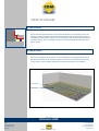
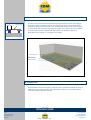
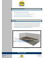
V EU 01
Installation Manual
CDM-ISO-FLOAT
Discrete Isolator System for Floors
CDM-ISO-FLOOR
CDM
Reutenbeek 9-11
BE-3090 Overijse
Belgium
noise & vibration control
T: + 32-2-6877907
F: +32-2-6873552
E: [email protected]
www.cdm.be
Contents
A. Lateral Isolation
B. CDM-ISO-FLOAT
C. Tolerance Zones
D. Protection Foil
E. Reinforcement Grid and Concrete
F. Finishing
Figures
1. Installation of prefabricated CDM-ISO-FLOAT panels
2. Covering the tolerance zones
3. Finishing
Page 1 of 4
CDM-ISO-FLOOR
CDM
Reutenbeek 9-11
BE-3090 Overijse
Belgium
noise & vibration control
T: + 32-2-6877907
F: +32-2-6873552
E: [email protected]
www.cdm.be
STEPS TO FOLLOW
A. Lateral Isolation
Ensure that the structural floor is dry and free of obstacles, discontinuities, dust, etc.
Along the perimeter of the slab, install lateral isolation with mineral wool to ensure a
complete decoupling with respect to surrounding walls and structure (also islands like
columns, ducting, etc.). The height must be up to the finishing level of the floor (see
figure on left).
B. CDM-ISO-FLOAT
For correct installation of the panels, use the installation plan provided which clearly
shows the individual panels and their reference numbers (as indicated in the factory
on the panels). Lay the panels making sure to follow the sequence as indicated.
Lateral Isolation
CDM-ISO-FLOAT
Figure 1: Installation of prefabricated CDM-ISO-FLOAT panels
Page 2 of 4
CDM-ISO-FLOOR
CDM
Reutenbeek 9-11
BE-3090 Overijse
Belgium
noise & vibration control
T: + 32-2-6877907
F: +32-2-6873552
E: [email protected]
www.cdm.be
C. Tolerance Zones
T
coverplate or
adjustment plate
In order to cope with the dimensional discrepancies between the plan (according to
which the system is produced) and the real situation (on site), it is good practice to
integrate so called “tolerance zones” in 2 perpendicular directions, as shown in figure
2. Close off the tolerance zones by means of a larger cover plate in the same material
as the formwork (usually supplied with the system). The tolerance capacity is
dependent on the overlap “T” (see figure on the left).
Lateral Isolation
CDM-ISO-FLOAT
Tolerance Zones
Figure 2: Covering the tolerance zones
D. Protection Foil
Install protection foil over the panels, tolerance zones, and lateral isolation in order to
make sure that no concrete water can penetrate the system. It is recommended to
install this foil with sufficient overlaps.
Page 3 of 4
CDM-ISO-FLOOR
CDM
Reutenbeek 9-11
BE-3090 Overijse
Belgium
noise & vibration control
T: + 32-2-6877907
F: +32-2-6873552
E: [email protected]
www.cdm.be
E. Reinforcement Grid and Concrete
Install reinforcement grid. In the case concrete is:
• 4’’ [100 mm] thick a single grid is sufficient
• 6’’ [150 mm] thick advised to use 2 grids (bottom and top)
• 8‘’ [200 mm] thick always 2 grids (bottom and top)
Once this is ready, pour layer of concrete up to desired level.
F. Finishing
Install finishing: floor covering + plinth (skirting board). The floating floor should have
no rigid contact with the surrounding structure. Please note that, since the isolators
are made of rubber, there will be some deflection over time (couple of millimeters),
called creep. In case the concerning room is finished with plinths along the perimeter
directly after the installation, it is advised to use a very flexible putty between the
floor and the plinth in order to cope with the creep issue.
Lateral Isolation
Finishing
Concrete
Protection Foil
Tolerance Zone
CDM-ISO-FLOAT
Figure 3: Finishing
Page 4 of 4
CDM-ISO-FLOOR
CDM
Reutenbeek 9-11
BE-3090 Overijse
Belgium
noise & vibration control
T: + 32-2-6877907
F: +32-2-6873552
E: [email protected]
www.cdm.be