1
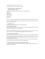
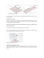
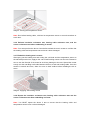
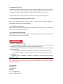
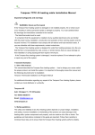
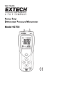
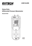
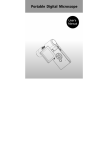
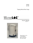
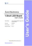
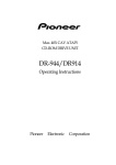
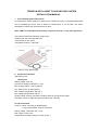
TEMPSON INTELLIGENT FLOOR HEATING SYSTEM
INSTALLATION MANUAL
1. Floor Heating System Description
It’s designed for comfort heating of ceramic tile or natural stone floors. The preassembled mats
can be installed over wood, with or without a backer-board, or on concrete. The mat is
embedded in mortar and covered with tile or stone.
But it CAN’T be installed beneath wooden, carpeted, linoleum, or any other type floors.
The system includes the following components,
*Heating mat, with 10ft cold lead each
*Thermostat: UL/cUL listed
*Temperature sensor, 10ft length
Image 1: Floor Warming Kit
2. System specifications
Approved by CUL
Heating mat
Rating voltage: 120V AC
Power unit: 12W/ft2 (130W/m2) +/-10%
Min. bending radius: 1.25inch (30mm)
Min. cable space: 3inches (80mm)
Max. ambient temperature: 85F (30 )
Min. Installing temperature: 40F (5 )
Heating Cable: 2 wires, grounded, insulation jacket by fluoropolymer plastic
Cold lead: 2 wires 17 AWG with ground braid, length 10ft (3m)
TP 150 Thermostat
Function: On/off controlling by digital display,
7 day programmable, class A, 5mA GFCI
Rating voltage: 120V/240V AC +/-10%
Max. switch current: 16A
Temperature controlling range: 40~122F (5~50 )
Ambient temperature range: 23~122F (-5~50 )
Temperature sensor: 2 wires, lead wire 10ft (3m)
3. Installation your floor heating system
Tools and materials needed
You need following items to install and test your floor warming system,
*Scissor
*Utility knife
*Wire stripper
*Tape measure
*Screwdriver
*Multimeter
Also you will need the appropriate tools and materials to install the particular floor, include
products like self-leveling mortar, thin-set mortar, backer board, tile, notched trowel, and any
others for your specific floor.
3.2 Installation steps
Please follow below steps to ensure a successful installation.
3.2.1 Preparing the subfloor
Make sure that the floor area to be heated is clean, flat and free of debris what can damage
the mat, like nails, staples or protruding objects.
Drill or cut a hole through the wall sill plate under the electrical junction box location. You will
use this hole to route the cold lead and the temperature sensor wire to the box.
3.2.2 Orient the floor heating mat
Lay out the mat according to your original design, using as few turns as possible and ensuring
that the cold lead is near the electrical junction box. Remove the clear plastic lining and roll out
the mat with adhesive side down to temporarily hold it in place. If it’s necessary to change
directs, please refer step 3.2.3
If it’s necessary to remove the heating cable from the mesh to route around an obstacle, be
sure to maintain at least 3 inches space between heating cables.
3.2.3 Changing direction of heating mat to fit the floor design
To make a turn in the direction the mat is being installed, cut the mesh with scissor being not to
damage the heating cable.
Image 2: How to cut mesh
Image 3: Changing direction
The align the mat in the desired direction ensuring that the adhesive side of mat is down to roll
it into the position.
3.2.4 Route the cold lead
Position the cold lead close as possible to the wall near the electrical junction box, the cold
lead must be routed outside of heating mat, never under or over the heating cable and must
not protrude higher than the heating mat.
If the splice is higher than the mat, you must gouge out the sub floor to allow the splice
to lay flat under the tile.
Run the cold lead inside the wall to the electrical junction box location.
Note: Put the cord label on the cold lead inside the box. If it’s necessary to shorten the cold
lead, be sure to store the cord label in the junction box.
Image 4: Routing the cold lead
3.2.5 Place the temperature sensor
Center the sensor between two runs of the heating cable, 4 inches form the end of heating
cable loop (see image 4). Run the sensor inside the wall to the electrical junction box
location.
Image 5: Placing the temperature sensor
Note: Don’t allow heating cable, cold lead or temperature sensor to cross themselves or
each other.
3.2.6 Perform insulation resistance test, heating cable resistance test, and the
sensor resistance test before embedding in mortar.
Note: You must perform the above 3 test before embed the mat in mortar to confirm that
the heating cable and temperature sensor haven’t been damaged.
3.2.7 Embed the heating mat in mortar
After laying out the heating mat and routing the cold lead and the temperature sensor to
the electrical junction box, apply a thin coat of self-leveling mortar over the mat. Please be
sure to use the flat side of the trowel to avoid any damage to the mat. Spread the mortar
evenly over the mat filling in all voids between the floor, mesh and heating cable. Once the
surface is smooth and even, allow it to sure to hard surface before installing the tile or
stone.
Image 5: Applying self-leveling mortar
3.2.8 Repeat the insulation resistance test, heating cable resistance test and the
sensor resistance test after embedding in mortar.
Note: You MUST repeat the above 3 test to ensure that the heating cable and
temperature sensor have not been damaged.
3.2.9 Install tile or stone
To install tile or stone, apply a layer of acrylic or latex modified thin-set using the ridged
side of your trowel. Tile and grout the floor using best industry practices and in
accordance with instructions provided by the manufacturer of the tile or stone.
Don’t power the floor warming system until the thin-set and grout are fully cured.
3.2.10 Again repeat the 3 test after floor covering.
Note: You MUST repeat the above 3 test to ensure that the heating cable and
temperature sensor have not been damaged.
3.2.11 Install the thermostat
Please refer the document of thermostat installation manual, included in the thermostat
box for instructions on how to install it.
3.2.12 Program the thermostat
Please refer the document of thermostat installation manual, included in the thermostat
box for instructions on how to program it.
4. Additional important warnings
*Must observe this installation manual. It must conform the floor warming system
requirement of construction and floor’s structure, and electric condition.
*After laying out heating mat, no penetrating and drilling holes allowed to damage heating
cables and cold lead.
*Never cut down heating lead of cables (except cold lead per installation requirement.)
*The enclosed warranty and using instruction is to be completed by the electrician and
keeping properly.
*Observe above installation instructions basically, product quality warranty
certificate is valid.
Any technical issues, please consult your local distributor, or contact us directly
with following info,
Tempson AB
OAvägen 11
178 38 Ekerö
Sweden
Tel: +46 8 56030731
Email: [email protected]