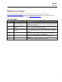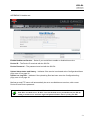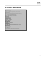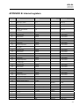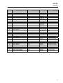
1
User Manual
SIU-DL DataLogger
Revision 3.20.1
SIU-DL
DataLogger
Revision 3.20.1
Revision List
Revision
Date
3.20.1
08-09-17
Chapter
Description
Match firmware release 3.20
Preface
The data and illustrations found in this document are not binding. We reserve the right to modify our
products in line with our policy of continuous product development. The information in this document is
subject to change without notice and should not be considered a commitment by Carlo Gavazzi AB. Carlo
Gavazzi AB assumes no responsibility for any errors that may appear in this document.
The document uses following pictures to get the reader’s attention:
Symbol
Description
Additional information for how to verify settings and how get the most out of SIU-DL
Note! Important information to avoid configurations that can cause problems and therefore
should be read carefully.
SIU-DL
DataLogger
Revision 3.20.1
Table of contents
Warranty and support .................................................................................................................................. 5 Terminology .................................................................................................................................................... 5 1 About the SIU-DL DataLogger............................................................................................................ 6 1.1 General .............................................................................................................................................. 6 1.2 Mounting............................................................................................................................................ 7 1.3 Connectors........................................................................................................................................ 8 1.3.1 ModbusRTU or Modem interface, RS-232 .......................................................................... 8 1.3.2 Ethernet interface .................................................................................................................... 9 1.3.3 Power supply connection........................................................................................................ 9 1.3.4 Digital inputs ............................................................................................................................. 9 1.3.5 RS232/RS485 interface ........................................................................................................ 10 1.4 LED Indicators ................................................................................................................................ 11 2 Getting started ..................................................................................................................................... 12 2.1 Configure the SIU-DL IP-address ............................................................................................... 12 2.1.1 About the SIU-DL Config utility ............................................................................................ 12 2.1.2 Installation ............................................................................................................................... 12 2.1.3 Scanning for connected devices ......................................................................................... 12 2.1.4 Changing IP settings ............................................................................................................. 14 2.2 Log in ............................................................................................................................................... 15 3 Web-page overview............................................................................................................................. 16 3.1 Browser requirements ................................................................................................................... 16 3.2 Menu overview ............................................................................................................................... 17 3.2.1 Configuration menu ............................................................................................................... 17 3.2.2 Setup menu ............................................................................................................................ 18 3.3 Status............................................................................................................................................... 20 3.4 Alarm ............................................................................................................................................... 21 3.4.1 Alarm history ........................................................................................................................... 22 3.5 Log ................................................................................................................................................... 23 4 Module Configuration ......................................................................................................................... 24 4.1 Work-flow ........................................................................................................................................ 24 4.2 Create a template .......................................................................................................................... 24 4.3 Device configuration ...................................................................................................................... 29 4.4 Pages............................................................................................................................................... 30 4.4.1 Adding parameters to web-page ......................................................................................... 31 4.4.2 Picture ..................................................................................................................................... 31 4.4.3 Page name.............................................................................................................................. 32 4.5 Alarm configuration........................................................................................................................ 32 Defining alarms ...................................................................................................................... 33 4.5.1 4.6 Log configuration ........................................................................................................................... 34 4.7 Bindings........................................................................................................................................... 35 5 Module Setup ........................................................................................................................................ 36 5.1 Users ............................................................................................................................................... 36 5.2 Modbus settings ............................................................................................................................. 38 5.2.1 Internal Registers ................................................................................................................... 39 5.3 Modem settings .............................................................................................................................. 40 5.3.1 Generic modem settings ....................................................................................................... 40 5.3.2 Dial-up/GPRS settings .......................................................................................................... 41 5.3.3 Dial-in settings ........................................................................................................................ 41 5.4 Regional .......................................................................................................................................... 42 SIU-DL
DataLogger
Revision 3.20.1
5.4.1 Time and date ........................................................................................................................ 42 5.4.2 Log file ..................................................................................................................................... 42 5.4.3 Module information ................................................................................................................ 43 5.5 Email Setup .................................................................................................................................... 43 5.5.1 SMTP Authentication ............................................................................................................ 44 5.6 SNMP Setup ................................................................................................................................... 45 5.7 Web-server Setup .......................................................................................................................... 46 5.8 Ethernet (TCP/IP) settings ........................................................................................................... 47 5.9 Backup............................................................................................................................................. 48 5.10 Firmware ......................................................................................................................................... 49 5.11 FTP .................................................................................................................................................. 49 5.12 Netbiter.net ..................................................................................................................................... 50 APPENDIX A: Specifications .................................................................................................................... 52 Ethernet connection .............................................................................................................. 52 APPENDIX B: Internal registers ............................................................................................................... 53 APPENDIX C: SNMP.................................................................................................................................... 55 APPENDIX D: Netbiter.net ......................................................................................................................... 56 SIU-DL
DataLogger
Revision 3.20.1
Warranty and support
To obtain fast and simple support for your SIU-DL, please use our Internet support service at
http://www.support-carlogavazzi.se. Here you will find the latest documentation, configuration utilities,
drivers etc. You can also contact our support at [email protected].
Terminology
Term
Extract
Description
TCP/IP
Transmission Control
Protocol/ Internet Protocol
TCP (Transmission Control Protocol) is a set of rules used along with the
Internet Protocol (IP) to send data in the form of message units between
computers over the Internet.
HTTP
Hyper Text Transfer
Protocol
HTTP is a set of rules for exchanging files (text, graphic images, sound,
video, and other multimedia files) on the Web.
DHCP
Dynamic Host Configuration DHCP is a standard protocol that automates the process of configuring
Protocol
network hosts by allowing hosts to obtain IP addresses and configuration
parameters
Gateway
A device that makes it possible to transfer data between networks of
different kind, e.g. Modbus/RTU and Modbus/TCP.
Template
Describes a Modbus slave device, as a collection of groups and
parameters.
Device
A Modbus slave unit that is connected to the SIU-DL.
5
SIU-DL
DataLogger
Revision 3.20.1
1 About the SIU-DL DataLogger
1.1
General
The SIU-DL DataLogger provides a web-based user interface for accessing data from connected
instruments as well as local data-logging and alarm management without using a PC. The SIU-DL
DataLogger module acts as a bridge from Modbus TCP to Modbus RTU, making it possible for a
Modbus TCP based controller to connect with Modbus RTU based devices.
Some DataLogger features
•
Graphical user interface that is easy to work with.
•
Support for device templates to allow easy and flexible management of configurations.
•
Advanced modem handling, with support for GSM/GPRS modems as well as
analogue (PSTN) modems.
•
Improved alarm handling, now with alarm history and SNMP support.
•
Language support.
•
Support for sending log-files with email or FTP.
SIU-DL DataLogger supports an RS-232 connection through a 9-pole DSUB or RS-485
(screw connection). It also supports 10/100Mbps Ethernet through a standard Ethernet connector
(RJ-45).
It can be configured via a user-friendly web-interface or by using the SIU-DL Config utility
(available at http://www.gavazzi.se/siu).
6
SIU-DL
DataLogger
Revision 3.20.1
1.2
Mounting
A – Snap on
B – Snap off
1 – Snap the SIU-DL on to the DIN-rail (as described on picture A above).
2 – Connect the Ethernet cable to the RJ45 connector.
3 – Connect the ModbusRTU network to the DSUB connector (RS-232) or the
screw connector (RS-485).
4 – Connect the Power Supply and apply power.
5 – Now you can start using the Gateway. Use the “SIU-DL Config utility” to configure the IP
address and other network settings. See section 2.1 Configure the SIU-DL IP-address on page 12
for further information.
The default IP address of the SIU-DL is 10.200.1.1
Please change this IP-address to a valid address in your network. Also, make sure
not to power up more than one network attached SIU-DL before IP-address is changed or
DHCP enabled.
7
SIU-DL
DataLogger
Revision 3.20.1
1.3
Connectors
1.3.1
ModbusRTU or Modem interface, RS-232
The 9-pole DSUB, male connector on the SIU-DL unit contains an RS-232 interface. This port can
be used to connect to any equipment with an RS-232 interface.
Pin number
Function
1
CD (Carrier Detect)
2
Rx (Receive)
3
Tx (Transmit)
4
DTR (Data Terminal Ready)
5
GND
6
DSR (Data Set Ready)
7
RTS (Request To Send)
8
CTS (Clear To Send)
9
RI (Ring Indicator)
Serial interface
(DSUB-9, RS-232)
Ethernet interface
(RJ-45, 10/100Mbps)
8
SIU-DL
DataLogger
Revision 3.20.1
1.3.2
Ethernet interface
The Ethernet interface supports 10/100Mbps, using a standard RJ-45 connector.
Serial interface RS-232/ RS-485
Power Supply
1.3.3
Power supply connection
The SIU-DL can be powered by a 9-28VAC/DC supply (Power requirement 2W).
1.3.4
Digital inputs
The digital inputs are opto-isolated, and can accept a 10-24VDC signal for logic HIGH input.
For logic LOW the voltage should be in the range 0-2VDC.
The status of the inputs can be read in the Gateway Internal Registers (if enabled).
See section 5.2.1 Internal Registers on page 39 for more information.
9
SIU-DL
DataLogger
Revision 3.20.1
RS232/RS485 interface
1.3.5
Pin number
Function
24
Vin+
23
Vin- (Ground connection)
22
Digital input 2+
21
Digital input 1+
20
Digital input Common
19
No Connect
18
No Connect
17
RS-232 Receive (Input)
16
RS-232 Transmit (Output)
15
Common
14
RS-485 Line A
13
RS-485 Line B
10
SIU-DL
DataLogger
Revision 3.20.1
1.4
LED Indicators
LED description
Name
Colour
Function
Module Status
OFF
No power
Green
Module is running in normal mode
Orange
During boot-up
Flashing Green
Serial Packet receive
Flashing Red
Serial Packet transmit
Orange
During boot-up
Flashing Green
Ethernet Packet received
Flashing Red
Ethernet Collision detected
OFF
No Ethernet Link detected
Green
Ethernet network detected, 10Mbps
Orange
Ethernet network detected, 100Mbps
Serial Link Status
Ethernet
Activity/Collision
Link
11
SIU-DL
DataLogger
Revision 3.20.1
2 Getting started
2.1
2.1.1
Configure the SIU-DL IP-address
About the SIU-DL Config utility
The SIU-DL Config utility is a PC-based configuration utility to set TCP/IP network settings in the
SIU-DL. This utility has the ability to scan the Ethernet network for connected SIU-DL devices and
let the user set IP-address, net mask, gateway, DNS and hostname for each unit.
2.1.2
Installation
System Requirements
•
Pentium 133 MHz or higher
•
5 Mb of free space on the hard drive
•
Win 95/98/ME/NT/2000/XP
•
Network Interface Card (Ethernet)
Installation Procedure
There are two methods to install the SIU-DL Config utility; either download it from the Carlo
Gavazzi website or use the installation CD-ROM.
•
Using the CD-ROM: Run “Setup-SIUDLConfig.exe” and follow the instructions.
•
From website: Download the self-extracting installation package “Setup-SIUDLConfig.exe”
from http://www.support-carlogavazzi.se/ search on keyword “SIU-DL” and run it.
2.1.3
Scanning for connected devices
First ensure that you have connected the SIU-DL units you want to install on the same Ethernet
network as the PC is connected to. Use standard Ethernet cables, straight-through or crossover
cable depending on how you connect to the device. See pictures below for details.
Connecting the SIU-DL to a hub or Switch
12
SIU-DL
DataLogger
Revision 3.20.1
Connecting the SIU-DL directly to a PC
When the SIU-DL Config utility is started, it will scan the Ethernet network for SIU-DL devices. All
detected devices will be presented in a list in the main window. If you want to force a new scan for
devices, you can press the “Scan” button.
IP - The IP address of the SIU-DL
SN - The subnet mask
GW - The default gateway
DHCP - Dynamically assigned IP address On/Off
Version - Firmware version
Type - Product type (DataLogger-Modbus)
MAC - The Ethernet MAC address
13
SIU-DL
DataLogger
Revision 3.20.1
Use the “Advanced Options” button to enable the SIU-DL Config DHCP Server. This is
useful when you have set DHCP to “On” in the SIU-DL, but don’t have a DHCP-server
available on the network.
2.1.4
Changing IP settings
To change the IP settings on a detected device, double-click on the device you want to configure in
the list of devices. This will open up a dialog where you can enter the desired IP configuration.
To obtain the necessary information about IP address, subnet mask etc. please contact your
network administrator.
DO NOT SET DHCP TO “ON” IF YOU DON’T HAVE A DHCP-SERVER
AVAILABLE ON THE NETWORK.
14
SIU-DL
DataLogger
Revision 3.20.1
Host Name - Here you can enter a hostname of your device (optional).
IP Address - The IP address of the SIU-DL.
Netmask - The subnet mask
Gateway - The default gateway
Primary DNS - The primary Domain Name Server (optional)
Secondary DNS - The secondary Domain Name Server (optional)
The default password for authentication of the new settings is “admin”.
Pressing “Set” will cause the SIU-DL device to reboot and after that the new settings will be
enabled.
You can test the new settings by opening a web-browser and enter the IP you
assigned to the device. If you selected DHCP and want to know what IP your device have been
assigned, you can do a new scan with the SIU-DL Config utility to view the new network
configuration.
2.2
Log in
Open a web browser (Internet Explorer for example) and enter the IP address you have set on the
SIU-DL unit with the SIU-DL Config utility. For example, if you entered the address
192.168.100.160 then you should enter the text below in the address field of the browser and press
enter.
http://192.168.100.160
Now you should see the login screen:
15
SIU-DL
DataLogger
Revision 3.20.1
To be able to configure the Gateway you should enter “admin” in the user-name box.
The default password is “admin”.
You can later change the default password to something else (recommended).
This will be described in section Users on page 36.
If you have problems to log in and you are sure that your password is correct, make
sure that
“Caps Lock” is not enabled on your keyboard.
3 Web-page overview
3.1
Browser requirements
The web-pages are optimized for Internet Explorer and Mozilla Firefox. Other browsers can work
as well, but the web-pages might appear differently. The browser must be JAVA enabled, to use
pages with JAVA content (like the graph page). If it’s not, please visit www.java.com to
download a JAVA-plugin for your browser.
The picture below shows the welcome screen which is shown when you first log into the module.
16
SIU-DL
DataLogger
Revision 3.20.1
The picture below indicates an example how the continuous data can be presented in the tables,
up to 20 values can be shown on every page. Choose a page from the drop list “Select page” to be
shown and click on “GO”.
3.2
Menu overview
To navigate on the web-pages, use the menu items available: Select Page(Go), Status, Alarm,
Log, Configuration and Setup.
Logout Button
3.2.1
Configuration menu
When you choose the Configuration menu, a sub menu will appear:
17
SIU-DL
DataLogger
Revision 3.20.1
•
The “Templates” configuration sub-menu will be used to create, edit and backup templates
for your devices.
•
On the “Devices” screen you define the devices which you connect to the DataLogger.
•
On the “Pages” screen you create and edit the structure of the presentation web-pages and
also select parameters to be presented.
•
The “Alarm” screen can be used to enable/disable SMS/Email/SNMP alarms, and also to
create and modify alarm parameters.
•
On the “Log” configuration screen it’s possible to configure the behaviour of the log-file,
and also create/modify log-parameters.
•
The “Bindings” configuration screen makes it possible to enable automatic parameter
“copying” from one Modbus slave to another at a configurable interval.
3.2.2
Setup menu
When you choose the Setup menu, a sub menu will appear:
•
The “Users” screen is where all things related to user management are handled.
•
The “Modbus” screen handles all ModbusRTU and ModbusTCP configuration.
•
The “Modem” screen handles all modem configurations (Analogue, GSM, GPRS, dial-up,
dial-in).
•
The “Regional” settings screen configures things like date/time and generic module
information.
•
The “E-mail” screen configures all that is needed to send emails from the DataLogger.
•
The “SNMP” screen makes it possible to configure SNMP trap properties.
•
The “Webserver” screen can be used to define which port the DataLogger web-server
should use.
•
The “Ethernet” screen handles all TCP/IP configurations, like IP-address, DHCP, DNS etc.
•
On the “Backup” screen it’s possible to backup/restore all settings, and also do a factory
reset of the DataLogger module.
•
The “Firmware” screen can be used to download new firmware to the module.
•
The “Netbiter.net” screen is used to setup the device to use the Netbiter.net services, see
APPENDIX C: SNMP
•
If SNMP Alarms is enabled, see page 32, all alarms will be sent as SNMP traps to the host
specified on the SNMP page, see section 5.6 on page 45.
The OID is sent in the following format in numbers:
.1.3.6.1.4.1.23312.1.1.2 [IP address][event]
.1.3.6.1.4.1.23312.1.1.[trap_id][trap_data]
18
SIU-DL
DataLogger
Revision 3.20.1
where.
23312 is Intellicom enterprise ID
1.1 is products SIU-DL DataLogger
and where event:
1 = Alarm set
2 = Alarm cleared
A trap id is divided into five messages with following trap data:
#1 Alarm ID
#2 Alarm description
#3 Class ID (1-10)
#4 Class description
#5 Alarm severity, where
0 = indeterminate
1 = critical
2 = major
3 = minor
4 = warning
5 = cleared
See the pictures for example of SNMP trap sent an alarm to warning of high temperature from a
SIU-DL.
To try out the SNMP functionality the software Trap Receiver could be used. This program can be
found at http://www.trapreceiver.com. Please, check the license for the software. It could be used
to examine a trap sent to a PC to better understand the SNMP functionality of the SIU-DL
DataLogger.
19
SIU-DL
DataLogger
Revision 3.20.1
•
APPENDIX D: Netbiter.net at page 55 for more information.
3.3
Status
This page shows some status information about the Modbus interface. The Status screen is split
into two columns, “Modbus/TCP messages” and “Other Modbus messages”. The Modbus/TCP
messages field shows information about requests that originate from a master attached to the
gateway, and Other Modbus messages field shows information about requests that originate from
either internal applications (Log/Alarm) or WebPages.
Number of connections - Indicates the number of open connections to a Modbus TCP master.
Internal queries indicate number of pending queries from WebPages + the internal connection from
(Alarm/Log) application.
Valid Responses - Counts valid responses from the Modbus/RTU slaves.
Serial Timeouts - The number of time-outs from attached slaves.
CRC Errors - The number of CRC errors on incoming Modbus/RTU responses.
Buffer Overruns - If an incoming Modbus/RTU response is larger than 300 bytes, this will cause
the input buffer to overflow.
Frame Errors - If an incoming Modbus/RTU response has incorrect length or some other fault in
the frame, this will cause a Frame Error.
Exception Responses - Counts all exception responses from the connected Modbus/RTU slaves.
20
SIU-DL
DataLogger
Revision 3.20.1
Modem Status
The modem status field gives information about what state an attached modem is in.
•
Connecting to Internet:
Calling Internet Service Provider and negotiate for a connection.
•
Waiting for incoming connection:
The unit is waiting for an incoming call.
•
Waiting for Event/Alarm:
The unit is in standby mode, and when an alarm or event appear it will connect to Internet.
•
Connection established:
A connection to Internet is established and data will be sent.
•
Incoming connection is in progress:
There is an incoming call and correct baud rate, user name and password is being verified.
•
Modem disabled:
Not possible to connect using the modem
3.4
Alarm
The Alarm page shows all active and unacknowledged alarms. It is also possible to select to view
the status of all configured alarms. Use the button in the lower left area of the screen to toggle
between the two modes.
21
SIU-DL
DataLogger
Revision 3.20.1
3.4.1
Alarm history
The “Alarm History” screen shows all alarms that have occurred. To clear this list, click the “clear
history” button.
22
SIU-DL
DataLogger
Revision 3.20.1
3.5
Log
From this page it’s possible to download the log file from the DataLogger (if logging has been
enabled). Simply click the “download” button to download/view the file, or click the “clear” button
to remove all data from the log-file. To view the log-file as a graph, make sure that JAVA is
installed on your computer.
The graph will show all parameters in the log-file, but in the graph it’s possible to select which
parameters to show (by clicking on the square next to the parameter name).The three first log
points will be displayed in the graph. To show a log-point just click the square in front of the
parameter name. To make it disappear from the view click the square again.
At the top right corner there navigation buttons:
Scroll graph up
Back to starting view
Scroll graph left
Zoom in
Scroll graph right
Zoom out
Scroll graph
down
23
SIU-DL
DataLogger
Revision 3.20.1
By using a left click on the mouse, keep the button down and release it at the diagonal corner of a
box the graph will zoom to that size.
By right clicking and keeping the button down the graph can be scrolled by moving the mouse.
4 Module Configuration
An important concept for the DataLogger is the usage of templates. This allows the user to define
templates for different products and configurations, and then easily re-use and distribute them. A
template contains properties for available parameters in a device of a certain type. These
properties includes: Parameter Names, Modbus register types and addresses, data scaling and
presentation.
See also Application Note AN-1003 for more details about how to create a configuration.
(Can be downloaded from www.intellicom.se/support).
4.1
Work-flow
Follow these steps to get your DataLogger operational:
1 – Do all generic Setup, like assigning an IP-address (Setup/Ethernet), add/modify users
(Setup/Users),
configure the Modbus interface (Setup/Modbus) and set date/time (Setup/Regional).
2 – Create a template (Configuration/Templates).
A Template consists of one or several groups, and each group is a collection of Modbus
Parameters.
3 – Define your Devices (Configuration/Devices).
Device is simply a Modbus slave, with a unique Modbus address. For each Device,
you apply a Template.
4 – Create your Application! Now you can define your web-pages, alarms, log entries and
bindings.
4.2
Create a template
Clicking on the “Configuration” and then “Templates” link will bring up the following screen:
To create a template, click the “add template” button. Enter the name of the template in the
window that pops up. Click “edit” to make it possible to add new groups (a collection of
parameters) and new parameters, or edit an existing template. From this page it is possible to
backup, restore (update templates) and delete templates.
24
SIU-DL
DataLogger
Revision 3.20.1
To upload a template click the “upload template” button to upload a template. There will be a
window appearing waiting for the user to browse to the template file, and click “upload template”
when the file is found.
Also check out the IntelliCom Template page, where templates from different manufacturers will be
published.
You must always add a Group, before you can add a Parameter.
When you have created a Group, and at least one parameter, it’s possible to edit the Parameter by
clicking the “edit” button. This will bring up the following screen (Edit Parameter):
25
SIU-DL
DataLogger
Revision 3.20.1
Click on the “?” to view the online help at the upper right corner of
the Edit Parameter window
26
SIU-DL
DataLogger
Revision 3.20.1
The “Edit Parameter” screen contains the following fields:
Name – Description of the parameter.
Type – Modbus type (Holding, Input, Coil, Discrete)
Address – Modbus address
Datatype - Defines the datatype of the Modbus register. Can be one of the following:
Unsigned 16 – 16-bit positive value
Signed 16 – 16-bit value, with sign
Unsigned 32 - 32-bit positive value. Most significant word (register) on low address.
Signed 32 - 32-bit value, with sign. Most significant word (register) on low address.
Unsigned 32 (swapped) - 32-bit positive value. Most significant word (register) on high address.
Signed 32 (swapped) - 32-bit value, with sign. Most significant word (register) on high address.
Float – 32-bit floating point. (IEEE-754) Most significant word (register) on low address.
Float (swapped) - 32-bit floating point. (IEEE-754) Most significant word (register) on high
address.
Double - 64-bit floating point. (IEEE-754) Most significant word (register) on low address.
Double (swapped) - 64-bit floating point. (IEEE-754) Most significant word (register) on high
address.
Scaling - The Modbus register value will be divided by the scale value before presented on the
web-page, logged or compared with for alarm.
It will be multiplied with the scale value before value is written to a slave device.
Examples:
Modbus register value = 510, Scale value = 10 Æ 51,0 will be viewed on web-page.
Modbus register value = 5118, Scale value = 100 Æ 51,18 will be viewed on web-page.
27
SIU-DL
DataLogger
Revision 3.20.1
Web-page input = 127,5 Scale value = 10 Æ 1275 will be written to Modbus register.
Offset – The Modbus register value will be subtracted with the offset value before it is presented
on the web-page, logged or compared with for alarm. If scaling is also in use it is done before the
offset is subtracted.
The Offset value will be added to the value before value is written to a slave device. If scaling is
also in use it is done after the offset is added.
Mask - Is used to mask out specific bits from the Modbus register, on the webpage the value is
presented in binary. The Modbus register will be masked (logic and) and shifted to the right before
the value is presented on the web-page, logged or compared with for alarm.
Examples:
Modbus register value = 214 (D6 hex), Mask = 240 (F0 hex) Æ 1101 (13) will be viewed on
web-page.
Presentation - Defines how a value will be represented on a page. Available options are:
Show as value
This option will read from the address and present the result at the view-page.
Writeable value
This option reads the value from the address and presents it. There will be a set button next to
the
value at the view-page which makes it possible to write to the address.
Show with enumeration
This option will read the value from the address and present it with the corresponding enum
string
(See Enum below).
Writeable value with enumeration
This option will read the value from the address and present it with the corresponding enum
string. There will be a drop down next to the value at the view-page where available enum strings
will be selectable. A selected value will be written to the address.
Enum - here the enum variables is defined in following format [number]=[string].
Each enum is separated by a semi colon ‘;’ with no blank spaces.
Examples:
0=Off;1=On
0=Sunday;1=Monday;2=Tuesday;3=Wednesday;4=Thursday;5=Friday;6=Saturday
Number of decimals – Defines how many decimals to use for this point.
Valid range – defines min and max value for a write parameter. If a user tries to enter a value
outside the range, a warning message will appear.
When you are finished with the Template, continue to the Device Configuration.
28
SIU-DL
DataLogger
Revision 3.20.1
4.3
Device configuration
On the Device Configuration page, you define which Modbus slaves are attached to the
DataLogger. To add a device, click the “add device” button. This will bring up the following screen:
Name – A description of the device.
Template – Defines which template that should be associated with this device.
Modbus/TCP server IP address – If using Modbus/TCP the IP address should be entered here.
When using Modbus/RTU it should be left blank.
Modbus/TCP server port – The port that is used for the Modbus/TCP communication.
Modbus slave address – Defines the Modbus address for this device.
The next step is to create your DataLogger application, by defining the look of the web-pages and
which alarms and log-parameters that should be available.
29
SIU-DL
DataLogger
Revision 3.20.1
4.4
Pages
To create a new page, click the “add page” button. This will bring up the General Page
Configuration:
On this page all page properties can be configured. A maximum of 20 Modbus points can be on
each page.
Next step is to define where to display the parameters. Simply click the “edit” button on the
position you want to work with.
30
SIU-DL
DataLogger
Revision 3.20.1
4.4.1
Adding parameters to web-page
Now select the Device, Group and Parameter and enter a description for this parameter, and finish
by clicking the “save settings” button. To check that everything is OK, go to the “Select page” in
the menu, select the page you have been working with and hit the “Go” button. You can also define
a “presentation format” and “presentation scaling” on this page.
Presentation format – You can select a different presentation for a value on the presentation
pages.
•
Default
Value is presented as it is configured in the Device template.
•
Hexadecimal
Value is presented in hexadecimal form.
•
Binary
Value is presented in binary form.
Presentation scaling – You can add an additional scaling on the value before it is presented on
the
web-page.
The value will be divided by the scale value before presented on the web-page. It will be
multiplied with the scale value before value is written to a slave device.
It is normally better to use the scaling in the Device template because that will also
include logging and alarm.
4.4.2
Picture
This option lets you choose a picture to be presented on the page. The picture must not be more
than 870 pixels wide and must be in gif, jpg or png-format. The picture will be sent to the device
when you press the “Upload” button. To remove a picture from the device, press the “Clear”
button.
There are maximum 800kB available for pictures. On the General Page configuration
section you can see how much space remains.
31
SIU-DL
DataLogger
Revision 3.20.1
4.4.3
Page name
This field can be used to give the page a more descriptive name. Click the “set as start
page” button if this page should be the first page to be presented when logging into the
module.
It’s also possible to change name on the Page menu (default “Overview” and
“Advanced Overview”).
4.5
Alarm configuration
The SIU-DL DataLogger can send alarm messages with email, SMS or SNMP (traps).
(SMS alarms require an external GSM modem). The alarm functionality can be enabled/disabled
on the Alarm configuration page.
A maximum of 64 alarm parameters can be configured.
To upload alarm status to Netbiter.net it has to be enabled on this page. Make sure that the
Netbiter.net account is activated on the page Setup/Netbiter.net, see section.
32
SIU-DL
DataLogger
Revision 3.20.1
4.5.1
Defining alarms
To add an alarm point, click on the “edit” button in the Alarm Configuration list. This will bring you
to the following screen. Here you need to select which parameter to use, and define the trigger
operation that will activate the alarm. You also need to define some properties like alarm class (110), and what strings should be in the subject and message field of SMS/Email alarms.
•
Trig On - this configures the trig condition for the alarm parameter. It’s possible to trigger
on a Value (‘Higher than’, ‘Lower than’, ‘Equal to’, ‘Not Equal to’, ‘Change of Value’) or on a
bit-field (‘Any bit’, ‘Neither bit’, ‘All bits’). The option ‘No response’ is used to send an alarm
if there is no response from the module.
•
Alarm class - Can be used to set different priorities on the alarm (class 1-10). The Alarm
Class has to be set for each user that alarm message will be sent to. This is done at the
configuration page for the user.
•
Severity – The severity of the alarm.
- Warning
- Minor
- Major
- Critical
- Indeterminate
The alarm could also have the severity Cleared, that cannot be set but will be sent via
SNMP when the alarm is in normal state.
Every alarm will be sent as a SNMP trap message.
•
Description – The text that is displayed in the alarm views and sent via SNMP.
•
Subject – Defines the text to be shown as Subject in the email/SMS
•
Message – The body of the alarm message
33
SIU-DL
DataLogger
Revision 3.20.1
4.6
Log configuration
SIU-DL DataLogger can be used to log Modbus registers. All data is stored in a CSV-file that can
be uploaded to a computer for further analysis in e.g. Excel. A maximum of 64 parameters can be
configured.
To start logging, click the “start” button.
•
Estimated Log Time – gives an estimate about how long it takes to fill the log-file.
•
Log interval – defines the sample interval.
•
Log type – choose whether to stop logging when the log has reached its maximum, or to
overwrite old values (circular log).
•
Send log interval – enable this if you want to send the log-files periodically with e-mail or
ftp. You can choose to send the log every hour, every day (will be sent around midnight) or
every week (Sunday at midnight). You will also need to activate this function on each user
that should receive the log-files.
Send log files with E-mail – enable this if you want to send the log-files periodically with
email with the Send log interval set above. Make sure that each user that should get the
logs by email has this function activated for the user. This is configured at Setup/User and
edit settings for that user, see section 5.1 on page 36.
•
Upload log files to ftp server – enable this to upload log-file to ftp server periodically with
email with the Send log interval set above. Make sure that the Netbiter.net account is
activated, or that there is a ftp-server stated at Setup/FTP, see section Fel! Hittar inte
referenskälla. on page Fel! Bokmärket är inte definierat..
When the log is stopped there will be no more log sent. When the logging is started again
the log will be cleared. To send the latest logged data there is a “send now” button before
restarting the logging.
34
SIU-DL
DataLogger
Revision 3.20.1
The log-file that is stored in the SIU-DL will contain historical data for a maximum of two
periods as defined in the “Send log files with E-mail” property. I.e. if you set this to every
day, the log-file in the SIU-DL will keep a maximum of two days historical.
See also Setup/Regional settings to make sure you have the correct settings for list separator and
decimal symbol, see section 5.4.2 on page 42.
To add a log-point, click the “add log parameter” button, and then the “edit” button. This will bring
you to the “Edit Log Entry” page.
Now you can select the Device/Group/Parameter you want to log, and also enter a description for
this
Log Entry. To finish, click the “save settings” button.
4.7
Bindings
Bindings are a feature that allows you to “copy” parameters from one Modbus device to another.
To add a binding, click the “add binding” button.
On the “Add Data Binding” screen you choose the Source and Destination parameter, and the
interval for the copying of data.
35
SIU-DL
DataLogger
Revision 3.20.1
5 Module Setup
If you click on the Setup menu option, a sub menu will appear. Here you can do all necessary
setup for things like user administration, modem settings and TCP/IP settings.
5.1
Users
If you press the “Users” link you will be transferred to the Users administration page. Here you can
add, edit and remove users. To add a user, press the “add user” button, and to modify/remove a
user click on the user you want to modify/remove.
36
SIU-DL
DataLogger
Revision 3.20.1
Here you can enter the User ID (used on the login screen), name, contact info and a password.
If an e-mail address is entered, then alarms will be sent to this address (if user is configured as an
alarm recipient and e-mail alarm is enabled).
If a mobile number is entered, then SMS-alarms will be sent to this number (if user is configured as
an alarm recipient and SMS-alarm is enabled).
To configure a user as an alarm-recipient, enable one or more of “Alarm classes” (Class 1-10). It
has to be set to get alarm mail or SMS for an alarm point with the corresponding alarm class set.
Make sure that the alarm has the correct alarm class set when edit the alarm point, see 4.5.1 on
page 33.
The user will only receive alarms that match this selection.
The “Receive log files via E-mail” option configures whether this user will receive logs via Email or
not. See Configuration/Log (section 4.6 on page 34) for more details about this function.
The language selection defines which language will be used for this user.
The user level defines what the user can do on the web-pages:
Read - View pages but can’t do any configuration or modify Modbus Registers
Write - Can view pages and modify Modbus registers, acknowledge alarms.
Admin - Read, Write and also configure the module (templates, devices, pages, alarms, log, and
bindings)
Super Admin - Read, Write, Admin and setup module like users, modem and Modbus settings.
To add/edit users, you must be logged in as a user with Super admin access.
37
SIU-DL
DataLogger
Revision 3.20.1
5.2
Modbus settings
If you press the Configuration/Modbus menu you will be presented with the following view:
Serial Settings (Modbus RTU/ASCII)
Transmission mode - Selects Modbus RTU or Modbus ASCII
Slave Response Timeout - The time that the module will wait for a response from a slave, before
a Serial timeout will occur. (Default 1000 ms)
Physical Interface - EIA-485 or EIA-232
Baudrate - 300, 600, 1200, 2400, 4800, 9600, 19200, 38400, 57600 or 115200 bps.
Character Format - Select number of stop bits and if parity should be enabled (Odd, Even).
Delay between polls - time to delay between Modbus messages.
Character delimiter - Number of milliseconds between characters in the Modbus frame. Set to
zero to use standard Modbus (3.5 characters)
Force function code 15 when writing single coil - If this option is Enabled, all writes to coils will
be done with function code 15. (Useful if slaves don’t support function code 05).
Force function code 16 when writing single register - If this option is Enabled, all writes to
registers will be done with function code 16. (Useful if slaves don’t support function code 06).
38
SIU-DL
DataLogger
Revision 3.20.1
Ethernet Settings (Modbus TCP)
Port number - Which port to use for Modbus TCP communication (502 default).
Gateway Registers - The address to the gateway internal registers (if enabled). See section 5.2.1
Internal Registers on page 39 for details about the internal registers.
Server Idle Timeout - This parameter gives the idle timeout in seconds for the Modbus/TCP
connection.
If the Gateway doesn’t receive any Modbus/TCP query within this time the connection will be
closed. (Default value is 60 seconds).
IP Authentication - This can be used to configure the IP-number that is allowed to connect to the
Gateway.
It is of great importance to ensure at the time of the procedure of assigning Modbus
device addresses, that there are not two devices with the same address. In such a case, an
abnormal behavior of the whole serial bus can occur, the Master being then in the
impossibility to communicate with all present slaves on the bus.
Internal Registers
5.2.1
If Gateway registers are enabled, queries sent to that address will not be forwarded to the Serial
Modbus/RTU network; the Gateway will respond to these queries by itself.
See Appendix B for a list of the internal registers.
Valid Modbus commands for internal registers:
Command Name
3
Read Holding Registers
6
Preset Single Register
16
Preset Multiple Registers
The internal registers are also available as an “internal template”, i.e. the registers
can be used on presentation pages and as alarms/log entries.
39
SIU-DL
DataLogger
Revision 3.20.1
5.3
Modem settings
On this page you setup an external modem (optional) that can be either a GSM/GPRS modem or
an analogue modem (PSTN).
5.3.1
Generic modem settings
Start with selecting the correct type of modem attached (GSM, Analogue, GPRS). Also set the
desired baudrate that the DataLogger should connect to the modem with.
In this section you can also enter a PIN-code for the GSM-modem. Clicking on the “modem info”
button will bring up a screen with some details about the modem (Signal strength etc).
40
SIU-DL
DataLogger
Revision 3.20.1
5.3.2
Dial-up/GPRS settings
In this section you find configuration to allow the DataLogger to connect to Internet using a modem.
Connection trigger – Specifies whether the DataLogger should always be connected to Internet
using the modem, or only connect when there is an alarm or event.
Host to ping – address to the Host that the DataLogger will ping when sending keep-alive
messages for the GPRS connection.
Ping timer – Specifies the interval for the keep-alive messages. (Set value as high as possible to
avoid unnecessary GPRS traffic).
Access Point Name (APN) – This is the gateway for all GPRS traffic. Contact your GSM/GPRS
operator for information about this.
Phone number – Phone number to dial (e.g. to an Internet Service Provider, ISP).
User name – This is the user name your ISP has assigned to you.
Password – Password to log into the ISP network.
5.3.3
Dial-in settings
The dial-in functionality can be used when someone wants to view the web-pages in the
DataLogger over a modem-link.
Local IP-number – This is the IP-number of the DataLogger, which the remote client will see when
creating the PPP-connection.
Remote IP-number – This is the IP-number that will be assigned to the remote client, when
creating the PPP-connection.
User name – This is the login that the remote client will use when creating the PPP-connection.
Password - This is the password that the remote client will use when creating the PPP-connection.
41
SIU-DL
DataLogger
Revision 3.20.1
5.4
Regional
The Regional page contains configuration for time and date, generic module information and also
configuration for how the log file list separator and decimal symbol should be represented.
5.4.1
Time and date
This configures the real-time clock on the module. The clock will continue to work during powerloss
(max. 1 week). To use NTP (Network Time Protocol), enable it and enter an NTP-server (or use
the default configuration). Also set the update interval (how often NTP will synchronise the time).
5.4.2
Log file
List separator - Can be either colon (,) or semi-colon (;).
Decimal Symbol – Can be either dot (.) or colon (,).
The list separator and decimal symbol should be selected so it matches the configuration on the
computer where the file will be analysed.
42
SIU-DL
DataLogger
Revision 3.20.1
Module information
5.4.3
The “Location” string can be used to add information about where the module is located
(address, building id etc.) This information will be viewed on all page-headers.
The “More information” field can be used to do notes about the installation.
5.5
Email Setup
The following configuration properties are available:
•
SMTP server – IP-number or domain name to the SMTP server that the module should use
when sending E-mails. If domain name is used make sure that you have entered a DNS
under the Network configuration. You can choose to use the Netbiter.net server to forward
emails. Simply click “Netbiter.net” and activate your Netbiter.net account, see section Fel!
Hittar inte referenskälla. on page Fel! Bokmärket är inte definierat..
- Port number: The port that is used by the SMTP-server for incoming mail given by your
Internet service provider. For custom servers this is set to port 25 as default. When using
the Netbiter.net services it is set to port 2525.
•
SMTP Authentication
- Authentication method: Auto, plain, login or cram-MD5
- User name
- Password
•
Sender – From field in the alarm mail. Example “SIU-DL”
•
Reply path – The E-mail address to send a mail to when someone reply on an alarm mail.
43
SIU-DL
DataLogger
Revision 3.20.1
5.5.1
SMTP Authentication
If the SMTP server require authentication you should enable SMTP Authentication. There are
several types of authentication methods supported by the module:
•
auto – The module automatically select the best method supported by the SMTP server.
•
plain – a simple non-encrypted method supported by most SMTP servers.
•
login – a simple non-encrypted method supported by most SMTP servers.
•
cram-md5 – a more secure login method where the user name and password is encrypted.
(This method is not supported by all SMTP servers).
•
Note: auto will not work if only plain and login is supported by the SMTP server,
because the module find these methods too insecure, in that case “login” or “plain”
must be must be set explicit.
To verify the setup, use the Test E-mail functionality. Clicking on the “send” button will generate a
test
e-mail.
44
SIU-DL
DataLogger
Revision 3.20.1
5.6
SNMP Setup
The SNMP Setup page contains configuration to be able to send SNMP traps.
•
SNMP Manager – The SNMP manager to which SNMP traps should be sent
•
Port – The port number on the SNMP manager to which traps should be sent
If SNMP is activated for alarms, see section 4.5 on page 32, all alarms will be sent by using SNMP.
There is a MIB-file for SIU-DL DataLogger that can be downloaded from http://support.intellicom.se
45
SIU-DL
DataLogger
Revision 3.20.1
5.7
Web-server Setup
The Web server Setup page contains a configuration to change the port number of the internal
web-server in the DataLogger and also enable/disable the low bandwidth pages.
Extra webserver port - To connect to the Extra webserver port the URL should have a colon ‘:’
followed by the new port number, i.e. http://10.10.10.30:8080 where 10.10.10.30 is the IP number
or DNS address to the SIU-DL and :8080 the new port.
Compression on web pages – (Only used for the Extra webserver port) is used to improve the
data transfer for low bandwidth connection, such as modem connection. The SIU-DL DataLogger
will check if the connecting web browser support compressed data transfers, and then compress
the web-pages before sending them.
When compression is used the workload of the SIU-DL will increase, and that is why this feature is
not enabled by default.
There is an option to ‘disable’ compression and the pages will be sent as normal web pages,
which always is the case for the standard web server port 80.
If it is set to ‘force’ web pages will always sent compressed regardless the support of the web
browser. In some cases the information if the web browser supports compressed data will be
altered in the network route, as with Microsoft ISA server default setting for controlling port 80. To
ensure that compressed web pages are sent anyway the option ‘force’ is set. Most web-browsers
supports compressed data.
Auto update values and status – (Only used for the Extra webserver port) to
minimize the amount of data transferred over a connection with http compression.
The data will be read only one time. To refresh values and status the refresh button
at the upper left corner has to be clicked. If the web-browser reload button is used
instead, unnecessary data-traffic will be generated.
Automatic logout time - defines the time-interval before a user is logged out from the web-server.
Note: The webserver will always listen on default port 80.
Note: When using modem connection, compression on web pages will always be
enabled and Auto update will always be disabled to improve response time, and the
refresh button has to be clicked to update values and status.
46
SIU-DL
DataLogger
Revision 3.20.1
5.8
Ethernet (TCP/IP) settings
If you press the Configuration/Ethernet link you will be presented with the following view:
On this page you can view and change the TCP/IP network settings in the module. These settings
are the same as the ones set by the SIU-DL Config utility.
Dynamic IP: Select this if you have a DHCP server on your network and you want the IP address
be assigned automatically by the server.
DO NOT SELECT THE DYNAMIC IP OPTION IF YOU DON’T HAVE A DHCP SERVER
AVAILABLE ON THE NETWORK.
Host Name: Here you can enter a hostname of your device (if E-mail alarms should be used this
field must contain something)
IP Address: The IP address of the SIU-DL.
Netmask: The subnet mask
Gateway: The default gateway
Primary DNS: The primary Domain Name Server (optional)
Secondary DNS: The secondary Domain Name Server (optional)
47
SIU-DL
DataLogger
Revision 3.20.1
5.9
Backup
The backup functionality makes it possible to backup and restore configurations.
By pressing the backup button you will get a backup file that can be stored locally.
All configurations in the Module except Ethernet settings will be in the backup.
To upload a backup to a module, press the Browse button and select an .nbb file, then press
restore.
After restoring the configuration, you will be asked to restart the module.
To bring a module back to Factory default configuration, click the “reset” button.
48
SIU-DL
DataLogger
Revision 3.20.1
5.10 Firmware
Firmware - On the firmware page it’s possible to download a new firmware image (.nbu file) or a
patch file (.nbp).
Software version – The MAC address for the module, the version of the kernel and the filesystem
version is displayed in this section.
Installed updates – If there are any updates installed on the system, the name, version and
description of the update will show here.
5.11 FTP
Files can be sent to a FTP server automatically. To use the Netbiter.net FTP server go to
Setup/Netbiter.net. If Netbiter.net is enabled it will override the settings on this web page. More
information about the Netbiter.net service can be found in section 5.11.
FTP-server - The server’s IP address or DNS name
User name - The user name for the server.
Password - Password for the server.
49
SIU-DL
DataLogger
Revision 3.20.1
5.12 Netbiter.net
Netbiter.net is a solution for remote management of SIU-DL® devices. This device is ready to
connect to the Netbiter.net services using the Device ID and password that was shipped with the
device.
More information about this service can be found in APPENDIX C: SNMP
If SNMP Alarms is enabled, see page 32, all alarms will be sent as SNMP traps to the host
specified on the SNMP page, see section 5.6 on page 45.
The OID is sent in the following format in numbers:
.1.3.6.1.4.1.23312.1.1.2 [IP address][event]
.1.3.6.1.4.1.23312.1.1.[trap_id][trap_data]
where.
23312 is Intellicom enterprise ID
1.1 is products SIU-DL DataLogger
and where event:
1 = Alarm set
2 = Alarm cleared
A trap id is divided into five messages with following trap data:
#1 Alarm ID
#2 Alarm description
#3 Class ID (1-10)
#4 Class description
#5 Alarm severity, where
0 = indeterminate
1 = critical
2 = major
3 = minor
4 = warning
5 = cleared
See the pictures for example of SNMP trap sent an alarm to warning of high temperature from a
SIU-DL.
To try out the SNMP functionality the software Trap Receiver could be used. This program can be
found at http://www.trapreceiver.com. Please, check the license for the software. It could be used
to examine a trap sent to a PC to better understand the SNMP functionality of the SIU-DL
DataLogger.
50
SIU-DL
DataLogger
Revision 3.20.1
APPENDIX D: Netbiter.net.
Enable Netbiter.net Service – Select if you would like to enable or disable this service.
Device ID – The Device ID received with the SIU-DL.
Device Password – The password received with the SIU-DL.
Upload alarm status and history – Indicates if the service is activated at the Configuration/Alarm
page, see 4.5 on page 32.
Upload csv Log files – Indicates if the upload log files has been set at the Configuration/Log
page, see 4.6 on page 34.
Mail server and FTP server will automatically be set to use Netbiter.net services, with correct
Device ID and Device password.
Some Internet Service Providers, ISP, has blocked the connection to the mail server other
than their own mail server. In these cases use the mail server provided from your ISP by
setting a custom server and enter login and password that is sent to you by your ISP.
51
SIU-DL
DataLogger
Revision 3.20.1
APPENDIX A: Specifications
Ethernet connection
10Base-T or 100Base-TX (IEEE 802.3). RJ45 connector.
Serial interfaces
RS-232 with full modem control (RTS,CTS,DCD,DTR,DSR,RI)
300-115.200bps, 9-pole DSUB connector
RS-485, 300-115.200bps, screw connector.
Power Supply
9-28VAC/DC (2W)
Temperature range
Operating : - 40 – 85 °C
Storage : -25 – 85 °C
Humidity range
5-95% RH, non-condensing
Cover material
Grey plastic, LEXAN 940, self-extinguishing acc. to UL94-V0
Mounting option
DIN rail (EN 50022)
CE certification
According to EN 61 000-6-4 and EN 61 000-6-2:2001
52
SIU-DL
DataLogger
Revision 3.20.1
APPENDIX B: Internal registers
Holding Name
register
Values
Options
Comment
1
Digital input 1 status
0 or 1
Read only
2
Digital input 2 status
0 or 1
Read only
3
Number Active Connections
MB/TCP
0-10
Read only
4
Number Active Internal
Connections
0-10
Read only
Serial Status (Modbus/TCP)
See section (3.3)
5
Valid responses
0-65535
Can be cleared
6
Serial timeouts
0-65535
Can be cleared
7
CRC errors
0-65535
Can be cleared
8
Input Buffer overruns
0-65535
Can be cleared
9
Frame errors
0-65535
Can be cleared
10
Exception responses
0-65535
Can be cleared
Serial Status (Buffered
messages)
11
Valid responses
0-65535
Can be cleared
12
Serial timeouts
0-65535
Can be cleared
13
CRC errors
0-65535
Can be cleared
14
Input Buffer overruns
0-65535
Can be cleared
15
Frame errors
0-65535
Can be cleared
16
Exception responses
0-65535
Can be cleared
Serial Status (Internal requests
and Webpages)
17
Valid responses
0-65535
Can be cleared
18
Serial timeouts
0-65535
Can be cleared
19
CRC errors
0-65535
Can be cleared
20
Input Buffer overruns
0-65535
Can be cleared
21
Frame errors
0-65535
Can be cleared
22
Exception responses
0-65535
Can be cleared
Default port number is 502
Configuration Registers
23
Modbus/TCP Port
1-65535
24
Gateway Modbus address
(-1)-255
25
26
Modbus/TCP idle timeout
-1
Disabled
0 - 255
Enabled
0-65535 (seconds)
Default
Default 60 seconds
0
Disabled
1 - 65525
Enabled
2400
2400 bps.
4800
4800 bps.
9600
9600 bps.
Baudrate
Default value
53
SIU-DL
DataLogger
Revision 3.20.1
Holding Name
register
27
Parity
Values
Options
19200
19200 bps.
38400
38400 bps.
57600
57600 bps.
115200
115200 bps.
Comment
0-2
0
No parity
1
Even parity
2
Odd parity
Default
28
Number of Stop bits
1-2
Default 1 stop bit
29
Slave timeout time
25-65535 (milliseconds)
Default 1000 ms.
30
Physical interface
0-2
0
EIA-485 (RJ12)
1
EIA-232 (DSUB)
2
EIA-232 (RJ12)
Default
Authentication
31
Valid IP address 1
0-255
First byte of IP address
0
Disabled
1-255
Enabled
IP address auth disabled
32
Valid IP address 2
0-255
Enabled
Second byte of IP address
33
Valid IP address 3
0-255
Enabled
Third byte of IP address
34
Valid IP address 4
0-255
Enabled
Fourth byte of IP address
35
Mask for Valid IP address 1
0-255
Enabled
First byte of mask
36
Mask for Valid IP address 2
0-255
Enabled
Second byte of mask
37
Mask for Valid IP address 3
0-255
Enabled
Third byte of mask
38
Mask for Valid IP address 4
0-255
Enabled
Fourth byte of mask
54
SIU-DL
DataLogger
Revision 3.20.1
APPENDIX C: SNMP
If SNMP Alarms is enabled, see page 32, all alarms will be sent as SNMP traps to the host
specified on the SNMP page, see section 5.6 on page 45.
The OID is sent in the following format in numbers:
.1.3.6.1.4.1.23312.1.1.2 [IP address][event]
.1.3.6.1.4.1.23312.1.1.[trap_id][trap_data]
where.
23312 is Intellicom enterprise ID
1.1 is products SIU-DL DataLogger
and where event:
1 = Alarm set
2 = Alarm cleared
A trap id is divided into five messages
with following trap data:
#1 Alarm ID
#2 Alarm description
#3 Class ID (1-10)
#4 Class description
#5 Alarm severity, where
0 = indeterminate
1 = critical
2 = major
3 = minor
4 = warning
5 = cleared
See the pictures for example of SNMP
trap sent an alarm to warning of high
temperature from a SIU-DL.
To try out the SNMP functionality the
software Trap Receiver could be used.
This program can be found at
http://www.trapreceiver.com. Please,
check the license for the software. It could
be used to examine a trap sent to a PC to
better understand the SNMP functionality
of the SIU-DL DataLogger.
55
SIU-DL
DataLogger
Revision 3.20.1
APPENDIX D: Netbiter.net
The web site www.Netbiter.net collects and stores data from remote equipment. Through the
central server an authorized user can access the information at any time and from any location.
This is a free service from IntelliCom that gives customers to the SIU-DL DataLogger unique
possibilities.
The SIU-DL DataLogger devices connect to the central server to submit critical equipment data,
such as logged parameter data and alarms. At the server an authorized user can view and manage
this information. The only tool the user needs is a standard web browser. The use of one central
location for all remote equipment simplifies the work for anyone dealing with remote installations.
The Netbiter.net service provides the following functions:
•
Administrate and maintain users, projects, remote field units and data.
•
Storage of log files produced and sent by the SIU-DL DataLogger field units.
•
View logged data as trend graphs.
•
Management of active alarms and alarm history (alarm notifications updates automatically
on the server).
•
View the physical location of remote equipment on a map.
•
Etc
This service from IntelliCom is free!
Netbiter.net features
Trending
Store data log files at Netbiter.net and
view trend graphs of selected
parameter data.
Analyze trends to detect early warning
of malfunctioning equipment.
To be proactive to problems saves time
and money immediately as travels to
sites can be dramatically reduced.
56
SIU-DL
DataLogger
Revision 3.20.1
Positioning
View the location of remote equipment
on a map.
Easy and improved planning of service
routes saves time for any service
organization.
When an alarm occurs in equipment,
that unit in the map will automatically
be marked in red colour.
Management of users, projects…
One central place for management of
users, remote equipment and critical
information.
Store important blue prints, pictures,
templates and more.
Getting Started
To get started with Netbiter.net you need to have a SIU-DL with Netbiter.net Device ID, which is
found in the package.
Setup the SIU-DL device as it is described in section Fel! Hittar inte referenskälla. on page Fel!
Bokmärket är inte definierat..
Continue with creating an account on the Netbiter.net server by following these steps:
1. Go to www.Netbiter.net
2. If you do not have an account for Netbiter.net you have to create one, otherwise go to step
6.
3. At the lower left corner at the login screen click “create account”.
4. Enter registration data and read the terms and condition. Click register when ready
5. The e-mail address entered in the registration process will get an e-mail with an activation
key. Just click the URL to activate you Netbiter.net account.
6. Go to www.Netbiter.net and login using the user name and login.
7. Click Projects and create new project. Enter required information. Click “next” when ready
8. Enter the Device ID and password that was sipped with the device, and select a name for
the device. Enter additional information, when ready click “save”.
Now the system is up and running.
57