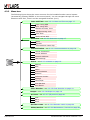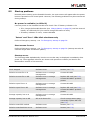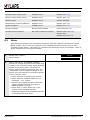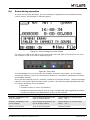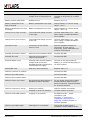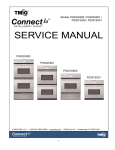
1
Portable Decoder
User Manual
(REVISION 2.1.7)
15 April 2010
Published by:
MYLAPS B.V.
Havenweg 15
6541 AD Nijmegen
The Netherlands
© 2010 No part of this document may be reproduced by any means without
the written consent of the publisher.
Whilst every care has been taken to ensure that the information in this
document is correct, no liability can be accepted by MYLAPS for loss,
damage or injury caused by any errors or omissions in this document.
Manual rev.
Software rev.
Date (d/m/y)
Amendments
(Revision 1.0)
(Revision 1.0)
17/3/08
This is the first version of this manual
(Revision 1.1)
(Revision 1.1)
15/9/08
Higher accuracy by using Curve Fitting Technology.
Graphical representation of NOISE.
Improved back-end storage with a maximum 160,000
registrations.
Various user interface and back-end improvements.
(Revision 2.0)
(Revision 2.0)
13/3/09
New transponder.
Extra menu selections.
Changed antenna connection.
(Revision 2.01)
(Revision 2.0)
10/4/09
New error messages added to Troubleshooting section.
New caution added to safety section for radio
interference.
(Revision 2.1.7)
(Revision 2.1.7)
15/4/10
New template used with ChampionChip references
changed to MyLaps in contact details, headings and
cover.
APEX name changed to Portable Decoder.
Page 2 of 54
Portable Decoder User Manual (Revision 2.1.7)
TABLE OF CONTENTS
. . . . . . . . . . . . . . . . . . . . . . . . . . . . . . . . . . . . . . . . . . . . . . . . . . . . . . TABLE OF CONTENTS3
. . . . . . . . . . . . . . . . . . . . . . . . . . . . . . . . . . . . . . . . . . . . . . . . . . . . . . . . . . LIST OF FIGURES5
1
2
3
4
5
6
7
8
INTRODUCTION . . . . . . . . . . . . . . . . . . . . . . . . . . . . . . . . . . . . . . . . . . . . . . . . . . . . . . 6
1.1 Scope of this manual. . . . . . . . . . . . . . . . . . . . . . . . . . . . . . . . . . . . . . . . . . . . . . . 6
1.2 How to use this manual. . . . . . . . . . . . . . . . . . . . . . . . . . . . . . . . . . . . . . . . . . . . . 6
SAFETY . . . . . . . . . . . . . . . . . . . . . . . . . . . . . . . . . . . . . . . . . . . . . . . . . . . . . . . . . . . . 7
2.1 General safety responsibilities . . . . . . . . . . . . . . . . . . . . . . . . . . . . . . . . . . . . . . . 7
2.2 Warnings and cautions . . . . . . . . . . . . . . . . . . . . . . . . . . . . . . . . . . . . . . . . . . . . . 7
PHYSICAL DESCRIPTION . . . . . . . . . . . . . . . . . . . . . . . . . . . . . . . . . . . . . . . . . . . . . . 8
3.1 Introduction . . . . . . . . . . . . . . . . . . . . . . . . . . . . . . . . . . . . . . . . . . . . . . . . . . . . . . 8
3.2 Controller. . . . . . . . . . . . . . . . . . . . . . . . . . . . . . . . . . . . . . . . . . . . . . . . . . . . . . . . 9
3.2.1
LED status panel. . . . . . . . . . . . . . . . . . . . . . . . . . . . . . . . . . . . . . . . . . . 9
3.2.2
Connectors . . . . . . . . . . . . . . . . . . . . . . . . . . . . . . . . . . . . . . . . . . . . . . 10
3.3 Antenna. . . . . . . . . . . . . . . . . . . . . . . . . . . . . . . . . . . . . . . . . . . . . . . . . . . . . . . . 10
3.4 ProChip . . . . . . . . . . . . . . . . . . . . . . . . . . . . . . . . . . . . . . . . . . . . . . . . . . . . . . . . 11
FUNCTIONAL DESCRIPTION . . . . . . . . . . . . . . . . . . . . . . . . . . . . . . . . . . . . . . . . . . 13
4.1 Basic principle . . . . . . . . . . . . . . . . . . . . . . . . . . . . . . . . . . . . . . . . . . . . . . . . . . . 13
4.2 Date and time . . . . . . . . . . . . . . . . . . . . . . . . . . . . . . . . . . . . . . . . . . . . . . . . . . . 14
4.3 System controls. . . . . . . . . . . . . . . . . . . . . . . . . . . . . . . . . . . . . . . . . . . . . . . . . . 14
4.3.1
Operator control panel . . . . . . . . . . . . . . . . . . . . . . . . . . . . . . . . . . . . . 14
4.3.2
Main Screen . . . . . . . . . . . . . . . . . . . . . . . . . . . . . . . . . . . . . . . . . . . . . 15
4.3.3
Menu tree . . . . . . . . . . . . . . . . . . . . . . . . . . . . . . . . . . . . . . . . . . . . . . . 16
SETUP AND REMOVAL . . . . . . . . . . . . . . . . . . . . . . . . . . . . . . . . . . . . . . . . . . . . . . . 21
5.1 Setting up Portable Decoder . . . . . . . . . . . . . . . . . . . . . . . . . . . . . . . . . . . . . . . . 21
5.2 Removal and storage . . . . . . . . . . . . . . . . . . . . . . . . . . . . . . . . . . . . . . . . . . . . . 24
OPERATION . . . . . . . . . . . . . . . . . . . . . . . . . . . . . . . . . . . . . . . . . . . . . . . . . . . . . . . . 26
6.1 Marker types . . . . . . . . . . . . . . . . . . . . . . . . . . . . . . . . . . . . . . . . . . . . . . . . . . . . 26
6.1.1
New file . . . . . . . . . . . . . . . . . . . . . . . . . . . . . . . . . . . . . . . . . . . . . . . . . 26
6.1.2
Gun . . . . . . . . . . . . . . . . . . . . . . . . . . . . . . . . . . . . . . . . . . . . . . . . . . . . 27
6.1.3
Marker . . . . . . . . . . . . . . . . . . . . . . . . . . . . . . . . . . . . . . . . . . . . . . . . . . 27
6.2 Connect external battery . . . . . . . . . . . . . . . . . . . . . . . . . . . . . . . . . . . . . . . . . . . 28
6.3 Retrieve data. . . . . . . . . . . . . . . . . . . . . . . . . . . . . . . . . . . . . . . . . . . . . . . . . . . . 29
6.3.1
Retrieving data (local network via Ethernet cable) . . . . . . . . . . . . . . . . 29
6.3.2
Retrieving data (GSM) . . . . . . . . . . . . . . . . . . . . . . . . . . . . . . . . . . . . . 30
6.3.3
Retrieving data via internet (CCNET Ethernet) . . . . . . . . . . . . . . . . . . . 31
MAINTENANCE . . . . . . . . . . . . . . . . . . . . . . . . . . . . . . . . . . . . . . . . . . . . . . . . . . . . . 32
7.1 Periodic maintenance schedules . . . . . . . . . . . . . . . . . . . . . . . . . . . . . . . . . . . . 32
7.2 Clean. . . . . . . . . . . . . . . . . . . . . . . . . . . . . . . . . . . . . . . . . . . . . . . . . . . . . . . . . . 33
7.3
. . . . . . . . . . . . . . . . . . . . . . . . . . . . . . . . . . . . . . . . . . . . . . . . . . . . . . . . . . . . . . 35
7.4 Check/Update software. . . . . . . . . . . . . . . . . . . . . . . . . . . . . . . . . . . . . . . . . . . . 35
7.5 Calibrate battery indicators . . . . . . . . . . . . . . . . . . . . . . . . . . . . . . . . . . . . . . . . . 36
7.6 Remove/replace SD card . . . . . . . . . . . . . . . . . . . . . . . . . . . . . . . . . . . . . . . . . . 37
7.7 Remove/replace SIM card. . . . . . . . . . . . . . . . . . . . . . . . . . . . . . . . . . . . . . . . . . 38
7.8 Replace battery . . . . . . . . . . . . . . . . . . . . . . . . . . . . . . . . . . . . . . . . . . . . . . . . . . 38
7.9 Emergency startup . . . . . . . . . . . . . . . . . . . . . . . . . . . . . . . . . . . . . . . . . . . . . . . 39
TROUBLESHOOTING . . . . . . . . . . . . . . . . . . . . . . . . . . . . . . . . . . . . . . . . . . . . . . . . 40
8.1 Troubleshooting principles . . . . . . . . . . . . . . . . . . . . . . . . . . . . . . . . . . . . . . . . . 40
8.2 Start up problems . . . . . . . . . . . . . . . . . . . . . . . . . . . . . . . . . . . . . . . . . . . . . . . . 41
8.3 Noise . . . . . . . . . . . . . . . . . . . . . . . . . . . . . . . . . . . . . . . . . . . . . . . . . . . . . . . . . . 42
8.4 Errors during operation . . . . . . . . . . . . . . . . . . . . . . . . . . . . . . . . . . . . . . . . . . . . 43
Portable Decoder User Manual (Revision 2.1.7)
Page 3 of 54
8.5
8.6
8.7
Problems with updating software . . . . . . . . . . . . . . . . . . . . . . . . . . . . . . . . . . . . 46
Reset to factory defaults . . . . . . . . . . . . . . . . . . . . . . . . . . . . . . . . . . . . . . . . . . . 46
GPS reception is weak or lost . . . . . . . . . . . . . . . . . . . . . . . . . . . . . . . . . . . . . . . 47
APPENDICES . . . . . . . . . . . . . . . . . . . . . . . . . . . . . . . . . . . . . . . . . . . . . . . . . . . . . . . . . . . . 48
Appendix 1: Preliminary installation instructions . . . . . . . . . . . . . . . . . . . . . . . . . . . . . 49
Appendix 1: Specifications . . . . . . . . . . . . . . . . . . . . . . . . . . . . . . . . . . . . . . . . . . . . . . 50
Appendix 2: CE Declaration . . . . . . . . . . . . . . . . . . . . . . . . . . . . . . . . . . . . . . . . . . . . . 52
. . . . . . . . . . . . . . . . . . . . . . . . . . . . . . . . . . . . . . . . . . . . . . . . . . . . . . . . . . . . . . . . . . INDEX53
Page 4 of 54
Portable Decoder User Manual (Revision 2.1.7)
LIST OF FIGURES
Figure 3.1
Figure 3.2
Figure 3.3
Figure 3.4
Figure 3.5
Figure 3.6
Figure 4.1
Figure 4.2
Figure 4.3
Figure 8.1
Figure 8.2
Figure 8.3
Portable Decoder controller (front and rear). . . . . . . . . . . . . 9
Controller status panel . . . . . . . . . . . . . . . . . . . . . . . . . . . . . 9
Controller connectors . . . . . . . . . . . . . . . . . . . . . . . . . . . . . 10
Antenna . . . . . . . . . . . . . . . . . . . . . . . . . . . . . . . . . . . . . . . 10
ProChip. . . . . . . . . . . . . . . . . . . . . . . . . . . . . . . . . . . . . . . . 11
ProChip in ankle band and attached to bicycle . . . . . . . . . 12
ProChip passing antenna . . . . . . . . . . . . . . . . . . . . . . . . . . 13
Operator control panel . . . . . . . . . . . . . . . . . . . . . . . . . . . . 14
Main screen . . . . . . . . . . . . . . . . . . . . . . . . . . . . . . . . . . . . 15
Error message on control screen . . . . . . . . . . . . . . . . . . . . 43
Error lamp. . . . . . . . . . . . . . . . . . . . . . . . . . . . . . . . . . . . . . 43
Pin settings . . . . . . . . . . . . . . . . . . . . . . . . . . . . . . . . . . . . . 51
Portable Decoder User Manual (Revision 2.1.7)
Page 5 of 54
1
INTRODUCTION
1.1
Scope of this manual
This manual is intended for operating, maintenance, and supervisory personnel and provides
information on installing, operating, and maintaining your unit.
The manual is divided into the following sections:
• Introduction - (this section)
• Safety (page 7): describes all safety aspects required when working with MYLAPS
equipment
• Physical description (page 8): physical descriptions of major components in the
unit
• Functional description (page 13): functional descriptions of the unit
• Setup and removal (page 21): site preparation, installation, and connecting power
supply and data cables among the components (also how to remove and store the
unit if required)
• Operation (page 26): how to start up, run, and shut down the unit
• Maintenance (page 32): instructions on how to maintain and repair the equipment.
Contains sub-sections for periodic maintenance schedules and corrective
maintenance procedures
• Troubleshooting (page 40): tables with potential problems, causes and solutions
• Appendices (page 48): contain unit specifications and CE declaration form
1.2
How to use this manual
This manual is designed to be used in electronic and printed form. Cross references in the
online version can be clicked to go directly to the referenced item. Navigation can be done
with the bookmarks and/or the table of contents, which contains live links. Page numbers are
also provided for ease of use with printed copy.
Before installing, operating or maintaining your Portable Decoder for the first time, always
read section 2 Safety on page 7 to familiarize yourself with the safety aspects of this manual
and your system.
To identify individual components, read 3 Physical description on page 8.
For an explanation of how the unit works, read 4 Functional description on page 13.
Read both 5 Setup and removal on page 21 and 6 Operation on page 26 completely to
overview the steps required to setup and run the unit. Refer to 8 Troubleshooting on page 40
to find solutions to setup/operating problems.
When performing scheduled maintenance on your unit, use 7.1 Periodic maintenance
schedules on page 32 to view the schedules and find the required maintenance procedures.
Corrective maintenance is guided from the tables in section 8 Troubleshooting on page 40.
Refer to the Appendices on page 48 for an overview of the technical specifications.
Page 6 of 54
Portable Decoder User Manual (Revision 2.1.7)
2
SAFETY
This section describes all safety aspects required when working with MYLAPS equipment. The
safety aspect can relate to potential equipment damage or to danger to personnel working
with this equipment or in the vicinity.
• When installing, operating or maintaining equipment, closely follow the prescribed
instructions in this manual, and use common sense at all times
• If ever in doubt about how to do a job or task safely, always ask for assistance
2.1
General safety responsibilities
High voltages, thermal and stored energy hazards are present in MYLAPS systems. Therefore,
pay special attention to safety when operating and maintaining each system, including:
• Meet all applicable codes, laws and field regulations
• Read and understand each item in this manual and follow the installation, operator
and maintenance procedures exactly
• Always use the correct tools for the job
• Take recommended precautions—never take short cuts
FCC Declaration
This equipment has been tested and found to comply with the limits for a Class A digital device,
pursuant to part 15 of the FCC Rules. These limits are designed to provide reasonable
protection against harmful interference when the equipment is operated in a commercial
environment. This equipment generates, uses, and can radiate radio frequency energy and, if
not installed and used in accordance with the instruction manual, may cause harmful
interference to radio communications. Operation of this equipment in a residential area is likely
to cause harmful interference in which case the user will be required to correct the interference
at their own expense.
2.2
Warnings and cautions
The following alerts are used in this manual:
• WARNINGS alert users of potentially dangerous situations.
• CAUTIONS alert users of potential equipment damage.
Warnings and cautions in this manual, are indicated by:
• an icon
• the text WARNING or CAUTION
• a textual description, which states the hazard and how to avoid it.
The following icons to highlight and warn of safety aspects are used in this manual, and are
attached to the Portable Decoder equipment at appropriate locations:
General
Caution or
Warning
Portable Decoder User Manual (Revision 2.1.7)
Dangerous
voltage
Grounding
required
Page 7 of 54
3
PHYSICAL DESCRIPTION
3.1
Introduction
Portable Decoder is a timing concept for sports where extreme accuracy and simple setup is
needed. The Portable Decoder system is portable and is designed for battery operation during
outdoor sports events.
The standard Portable Decoder system consists of the following components:
• Controller (housed in a sturdy Pelican case)
• Antenna - 6 m (20 ft)
• Antenna - 9 m (30 ft)
• Power cable (100 to 240 VAC)
• 12 VDC cable with battery terminals
• Coax cable with connection box - 5 m (16 ft)
• Ethernet cable - 10 m (33 ft)
• Torque screwdriver
• Flat screwdriver
• This Portable Decoder User Manual
The following components can be ordered from MYLAPS as options for further expanding the
Portable Decoder system:
• Extra antennas - varying lengths: 6 m (20 ft), 9 m (30 ft), 12 m (40 ft)
• ProChips
• Tape for attaching antenna to road surface (recommended Polyken#203 or Tesa
4651)
• Extension coax cables for connection box - 20 m (66 ft) and 100m (328 ft)
Additionally, you can purchase the following component from local suppliers:
• SIM card (this will depend on your country and GSM cellular provider)
See Appendix 1 Specifications on page 50 for complete specifications.
Page 8 of 54
Portable Decoder User Manual (Revision 2.1.7)
3.2
Controller
1
1
1
5
2
3
6
4
Figure 3.1 Portable Decoder controller (front and rear)
1 Accessory pouches
3 SD and SIM card slots
5 Logo
2 Control panel
4 LED status panel
6 Connectors (behind protective
plastic cover)
3.2.1
LED status panel
3
2
1
4
Figure 3.2 Controller status panel
1 Battery level indicators (E = empty; F = full) - see description below
3 SD and SIM card slots
2 Control panel
4 LED status panel
The battery level indicator LEDs light up from left to right as the controller is charging with
the following color definitions:
− red = 0-20% full
− yellow = 20-40% full
− 1st green = 40-60% full
− 2nd green = 60-80% full
− 3rd green = 80-100% full
Portable Decoder User Manual (Revision 2.1.7)
Page 9 of 54
3.2.2
Connectors
1
2
7
5
3
6
8
9
4
Figure 3.3 Controller connectors
1 Protective transparent cover
4 LED indicators network connect/
activity
7 LED indicator 100/240 VAC connected (red: <50% charged; orange: >50% charged; green:
battery charged)
2 Antenna connector
5 Ethernet connector port
8 100/240 VAC connector port
3 IO port (for start gun, etc.)
6 12 VDC connector port (external
battery)
9 LED indicator external battery status
3.3
Antenna
2
3
1
4
Figure 3.4 Antenna
1 Race track
3 Antenna connector box
2 Antenna (with balance resistor)
4 Coax cable
Lay the loop antenna wires across the width of the course in parallel to form a rectangle. The
loop length should not be less than 2 m (6.6 ft) or greater than 12 m (36 ft). The antennas
are plugged into a connector box with a coax cable attachment. The antenna must be laid to
suit ground surfaces as follows:
Page 10 of 54
Portable Decoder User Manual (Revision 2.1.7)
• Asphalt/concrete - use adhesive tape to affix the loop wires. We recommend Polyken
#203, Tesa 4651 or similar, 10 cm (4 inch) wide.
• Ice - cut slots 2 cm (1 inch) deep in the ice. Place the loop wires in the slots and fill
them with snow/water at least 12 hours prior to the start of the event to allow the
slot to re-freeze
• Snow - cut horizontal slots in the snow, approximately 20 cm (8 inch) deep. Place the
loop wires in the slots and fill them with snow.
3.4
ProChip
2
1
2
Figure 3.5 ProChip
1 Transponder (enclosed in plastic mold)
2 Attachment strip
The ProChip has the following features:
• Waterproof with attachment strip for fitting onto ankle band, running shoe, bike
• The chip is normally in 'sleep' mode until activated by the antenna. The chip will then
send a signal to the Portable Decoder controller - see 4.1 Basic principle on page 13
for more on this.
• After a first detection, a chip is only detected again by the controller after it is
removed from the antenna field for at least 2 seconds, even if the 'Time between
same chip' setting is lower than the time between two subsequent chip detections.
When worn in a race, the chip must be vertically aligned for best reception. See Figure 3.6
for an example of how to align the chip in an ankle band and attach to a bicycle with a tie
wrap.
Portable Decoder User Manual (Revision 2.1.7)
Page 11 of 54
Figure 3.6 ProChip in ankle band and attached to bicycle
Before use, each chip can be checked and registered as follows:
1.
Pass each chip over a connected antenna and check it is detected by Portable Decoder
(detection light, beep) - reject all defect chips.
2.
Record each chip number - the registered chips can be later assigned to individual
runners in a race.
Page 12 of 54
Portable Decoder User Manual (Revision 2.1.7)
4
FUNCTIONAL DESCRIPTION
4.1
Basic principle
Every participant in a MYLAPS timed event carries a registered Portable Decoder ProChip.
When this chip passes a Portable Decoder timing system antenna, the chip will emit a unique
code to identify itself and register the time it passed. The Portable Decoder controller reads
the data collected from the antenna and assigns the code of the chip with the registered time.
See following overview.
Figure 4.1 ProChip passing antenna
Detection heights depend on antenna width, ProChip orientation and road surface (reinforced
concrete under the road surface may reduce detection height). See following table for
guidelines for antenna widths and ProChip detection placement:
Race type
Antenna width cm (ft.)
ProChip placement
Ice skating
50 (1.7)
Strap around ankle
Inline skating
60 (2.0)
Strap around ankle
Cycling
60 (2.0)
Vertically mounted (low on bike)
Other
60 (2.0)
As applicable
NOTE: Always check detection height after installing an antenna.
Portable Decoder User Manual (Revision 2.1.7)
Page 13 of 54
4.2
Date and time
The Portable Decoder internal clock is extremely accurate when recording timing data. It can
be synchronized using time signals from GPS satellites. This guarantees precise time
synchronization between multiple Portable Decoder systems, and gives extreme accuracy
over a long period.
All date and time parameters are set via the menu selections on the control panel. See
4.3.1 Operator control panel on page 14 for more information.
NOTE: Never change the time during a race. When Portable Decoder is powered down, the
clock will no longer be accurate.
4.3
System controls
4.3.1
Operator control panel
4
1
2
3
3
5
6
3
3
Figure 4.2 Operator control panel
Control
Function
1
Display (showing
Main screen)
See 4.3.2 Main Screen on page 15
2
Esc button
For acknowledging errors and returning to Main screen from menus
3
Navigation arrow
buttons
For moving between menu selections (see 4.3.3 Menu tree on
page 16); can also be used to change a screen value
4
Power button
On/off switch for activating controller (with LED to show on/off
status)
5
Mark button
See 6.1.3 Marker on page 27
6
Enter button
To access menu selections or to confirm a setting
Table 4.1 Controls and their functions
Page 14 of 54
Portable Decoder User Manual (Revision 2.1.7)
4.3.1.1 Quick keys
The navigation arrow buttons (< >) have a 'quick key' function in certain menu selections to
access 'extra' screens (see 4.3.3 Menu tree on page 16 for the menu tree with all normal
selections).
Press < and > to move to and from menus and the following 'extra' screens:
MAIN MENU
<>
CHIP FILES
<>
CHIPS
SYNC USING GPS
<>
SYNC NOW
<>
GPS STATUS
SOFTWARE VERSION
<>
VERSION NUMBERS
<>
SERIAL NUMBERS
Table 4.2
4.3.2
Main Screen
6
7
1
8
2
9
10
3
4
5
Figure 4.3 Main screen
1 Power status - internal or external
battery, or AC power (and battery
full percentage) - see
4.3.3.4 Status on page 18
5 Number of detections for last chip
(during its most recent antenna
detect)
2 Last detected chip code
6 Communication status (none, 'Net'
or 'GSM') - see
4.3.3.3 Communication on
page 18
3 File number
7 Manually set Portable Decoder
time (MAN) or GPS time (GPS)
with number of GPS satellites in
view - see 4.3.3.1 Date and
Time on page 17
4 Number of detected chips in file
8 Current time, and time of last chip
9 Status messages
10 Marker type - choose here either
'New file', 'Gun' or 'Marker' (set
with 'Mark' button) - see
6.1 Marker types on page 26
NOTE: The backlighting for the screen dims after 2 minutes of inactivity; press the navigation
buttons or 'Esc' to fully illuminate screen.
Portable Decoder User Manual (Revision 2.1.7)
Page 15 of 54
4.3.3
Menu tree
The following figure shows the menu structure for the Portable Decoder control system
(accessed by pressing 'ENTER' on the control panel). You can navigate through the menu
selections with 'Esc', 'Enter' and the navigation buttons (< >).
Date and Time - see 4.3.3.1 Date and Time on page 17
Sync. using GPS
Sync. using NTP
Manual set Date, Time
Daylight saving Time
Time Zone
Notify at lost GPS
Detection - see 4.3.3.2 Detection on page 17
Sport
Squelch
Time between same chip
Communication - see 4.3.3.3 Communication on page 18
Server Connection
Server Address
Network Address
GSM Settings
Status - see 4.3.3.4 Status on page 18
Battery
GPS
Noise
Communication
Network
Software Version
Storage
View Vhips
View Markers
View Errors
Clear Decoder - see 4.3.3.5 Clear Decoder on page 19
Beeper - see 4.3.3.6 Beeper on page 19
IO Ports - see 4.3.3.7 I/O ports on page 20
Gun
Ext-1
Ext-2
Decoder name - see 4.3.3.8 Decoder name on page 20
Maint/Service - see 4.3.3.9 Maintenance / Service on page 20
Page 16 of 54
Portable Decoder User Manual (Revision 2.1.7)
4.3.3.1 Date and Time
NOTE: Never change time parameters after the system is setup for a race.
Sync using GPS
Synchronize the date and time in the Portable Decoder to the date and time received from
GPS satellites. If multiple Portable Decoderes are synchronized to GPS, precise time
synchronization (to the msec) is assured. The time required for the Portable Decoder GPS
module to correctly synchronize with GPS satellites can vary (up to 20 minutes for first-time
startup).
Sync using NTP
Synchronize the date and time in the Portable Decoder to the date and time received via the
Network Time Protocol. This protocol synchronizes the decoder clock over packet-switched,
variable-latency data networks.
Manual set Date, Time
Manually set the date and time in the Portable Decoder.
Daylight Saving Time
Switch on or off the daylight saving time (summer time); the Portable Decoder clock is
synchronized to summer time.
Time Zone
Change the time zone to configure the GPS time to local time.
Notify at lost GPS
Here you can set Portable Decoder to display a warning if it temporarily 'loses' its GPS
connection - the default setting is not to warn for a lost GPS signal. Normally, once the
Portable Decoder time has been synchronized to a GPS signal, the time is sufficiently accurate
and further synchronization with GPS should not be necessary.
4.3.3.2 Detection
Sport
• Other - Choose here for running, carting, etc.
• Cycling - Choose here for cycling events
• Skating - Choose here for normal skating events
• Ice Skating - Choose here for ice skating events
Squelch
The squelch setting lets you suppress weak ProChip signals. This is useful if participants are
walking near the antenna loop or the coaxial cable and are accidentally detected. For
example, if the squelch setting is 60 (instead of the default 30), all ProChips with a received
strength below 60 will be ignored.
Time Betw. Same Chip
If a chip is detected more then once within this interval, each new registration will be
neglected until the interval is over, or until a gunshot or marker is received.
Portable Decoder User Manual (Revision 2.1.7)
Page 17 of 54
4.3.3.3 Communication
Server Connection
• Off - Portable Decoder makes no connection to the CCNetServer
• CCNet GSM - Portable Decoder will try to connect to the CCNetServer via a GSM
internet connection
• CCNet Ethernet - Portable Decoder will try to connect to the CCNetServer via a cabled
internet connection
Server address
Configure here your own servers instead of the default 'CCNetServers'.
Network Settings
• IP Config Mode
− Automatic (DHCP) - Correct network setting will be automatically obtained from
DHCP server on local network, if available
− Manual - No automatic configuration; network settings as set in "Manual IP
Settings" menu will be used
• Manual IP Settings - Enter the following standard IP settings when "IP Config Mode"
is "Manual" or when no DHCP server is available:
− IP Address
− Netmask
− Gateway
− DNS
GSM Settings
Configures the GPRS connection of the GSM module. Settings must be obtained from your
GSM provider and entered in the following fields:
• APN (Access Point Name)
• Username
• Password
4.3.3.4 Status
Battery
• Maximum battery capacity (see 7.5 Calibrate battery indicators on page 36 for how
to calibrate)
• Current battery charge in mAh and as a percentage of capacity
• Current power source:
− internal battery
− external battery
− AC mains power is connected and charging battery
• Internal battery temperature
• Internal case temperature
• Current used (in mA)
Page 18 of 54
Portable Decoder User Manual (Revision 2.1.7)
GPS
Graphical display showing the number of satellites received and their signal strength.
Resetting the GPS will restart a search for satellites. See Appendix 1: Preliminary installation
instructions on page 49 for more on this option.
Noise
Portable Decoder determines the average background noise. The noise (and signal strength)
has a range of 0 to 255 points. Noise level, as shown on this status screen, should not exceed
40 points. If the noise level is higher, the received ProChip signal strength should be 60 points
above noise level to ensure proper functioning. So if the ProChip received signal strength is
120 points, the noise should not exceed 60 points. See 8.3 Noise on page 42 for more on this
option.
Communication
Shows the current communication method being used (shows if a server is connected or not).
Network
Shows MAC address and IP address, if available.
Software version
Shows the current software version and the build date. Also gives access to the software
update interface to upload new software version. See 7.4 Check/Update software on page 35
for more on this option
View Chips
View the chips stored in the current and previous files (since last "Clear Portable Decoder").
Storage
View the memory remaining on the SD card.
View Markers
View the markers registered by Portable Decoder with the time the marker was made, and
the type of marker.
View Errors
View the errors encountered by Portable Decoder with the time an error occurred.
4.3.3.5 Clear Decoder
Clear all chip registrations in the Portable Decoder. To be used before a new event.
4.3.3.6 Beeper
The following options are available for the beeper:
• Key Volume (volume heard when entering values on the control panel, or if an error
occurs)
• Chip Detect Volume (the volume heard when a chip is detected by the antenna - this
volume can be amplified by connecting an external beeper to the IO port at the back
of the case)
Portable Decoder User Manual (Revision 2.1.7)
Page 19 of 54
4.3.3.7 I/O ports
Here you can change the software interface to the I/O ports for an external connection for a
starter pistol (Gun) or other external devices. The default setting for these ports is 'normally
closed'.
4.3.3.8 Decoder name
Here you can assign a personalized name for easy identification when the Portable Decoder
is connected to a network. This name will be displayed next to the MAC/IP address in the
MYLAPS software.
Use the QWERTY keyboard in combination with the navigation buttons and Enter to assign
the name.
4.3.3.9 Maintenance / Service
Only for MYLAPS service engineer use, or after contact with MYLAPS. See 8.6 Reset to factory
defaults on page 46 for more on this option.
Page 20 of 54
Portable Decoder User Manual (Revision 2.1.7)
5
SETUP AND REMOVAL
This section describes how to setup the Portable Decoder equipment for a race, and then to
remove it after a race. Also described here is how to retrieve race data from the Portable
Decoder controller (see 5.2 Removal and storage on page 24).
5.1
1
Setting up Portable Decoder
Choose suitable antenna
• Measure total width of timing location
through which competitors will cross
• Select correct length antenna from
supplied antennas
2
Lay out antenna
• Lay out antenna in a rectangular shape,
equally spaced on either side of the start/
finish line and extending 30 cm (1 ft) more
than the track width on each side
• Measure the parallel distance between the
antenna leads and adjust the width to suit
the race; i.e. 60 cm (2 ft) for running,
50 cm (1.6 ft) for ice skating
• Attach the four corners of the antenna
leads with tape (for hard surfaces) or pegs
(for soft surfaces)
• Use tape or mats to cover the antenna
leads to ensure the leads will not cause a
hindrance to competitors crossing the line
3
Connect antenna
• Insert the antenna connectors into the
coax cable connector box
• Optionally, attach a multimeter to the
antenna ends to test the antenna
resistance (should be ±220 Ω)
4
Position the Portable Decoder controller so it
is easily accessible but not where it will hinder
competing athletes
Portable Decoder User Manual (Revision 2.1.7)
Page 21 of 54
5
Lift the protective cover at the back of the
Portable Decoder case and plug the coax cable
into the coax antenna connector
6
Click open both front latches on the case and
carefully open lid
7
Switch on Power
• Press the main Power button
• Wait until the Main screen appears (this
screen is described in 4.3.2 Main Screen on
page 15)
8
Check Main screen
• Check that no errors are displayed on the
screen - if so, refer to 8 Troubleshooting on
page 40 for how to solve them
• Check the battery level (shown as a % on
the top left of the main screen)
• If battery level is low, supply external
power by connecting a 12 VDC supply to
the connector at the back of Portable
Decoder case
9
Clear data in Portable Decoder memory
• Access the menu by pressing 'Enter'
• Choose 'Clear Portable Decoder'
Clear Portable
Confirm
• Select 'Confirm' and press 'Enter'
10 Synchronize time with GPS
• Select menu entry 'Date and Time'
Date and Time
• Select 'Sync using GPS'
Sync using GPS
• Verify if GPS is available (may take several
minutes) - eventually 'GPS' and 'no. of
satellites' is displayed in bottom right
corner of screen
• If no GPS is available, reposition Portable
Decoder for better satellite reception
• Press 'Sync now' and wait until time is
synchronized
Page 22 of 54
Portable Decoder User Manual (Revision 2.1.7)
11 Configure 'Detection' parameters by using the
menu selections to configure:
Detection
• Sport
Sport
• Squelch
Squelch
• Time Betw. Same Chip
Time Betw. Same
12 Configure 'Beeper'
• Use the menu selections to configure the
Chip detect volume
Beeper
Chip detect
13 Test Portable Decoder by carrying a chip (held
vertically) across the antenna area and check
• The chip is registered by the Portable
Decoder system at expected height
• No intermittent or irregular beep
• Reception height at both ends of the
antenna area is the same
14 Check Noise
• Select menu 'Status'
Status
• Select 'Noise'
Noise
• Check the Noise level - if the display shows
consistent readings above 40, refer to
8 Troubleshooting on page 40 for how to
solve
15 Set up communication
• Select menu 'Communication'
Communication
• Choose appropriate communication
method for your situation - see
4.3.3.3 Communication on page 18 for
more on communication
Important: For GSM communication, make sure
your provider settings are entered - see
Appendix 1: Preliminary installation
instructions on page 49
16 Attach starter pistol (optional)
• If required, attach a starting pistol (and/or
other triggers) to the I/O port at the rear of
the Portable Decoder case
Portable Decoder User Manual (Revision 2.1.7)
Page 23 of 54
5.2
1
Removal and storage
Retrieve race data (if not already done):
• Refer to 6.3 Retrieve data on page 29 to
see how to retrieve data (race results) from
the Portable Decoder
• Verify data has been retrieved before
proceeding. If no data connection to a
results computer is immediately available,
data can be retrieved later
2
Switch off power
• Press 'Power' button
• Choose "Confirm''
3
Disconnect all cables
• Remove coax cable
• Remove power cable (if connected)
• Remove Ethernet cable (if connected)
• Remove starter pistol cable from I/O port
(if connected)
4
Disassemble antenna(s) and other equipment
• Remove the antenna cables from the coax
cable connector box
• Carefully remove antenna(s) from
measuring points and load them into their
carry bags in the Portable Decoder case
• Load all other accessories into their carry
bags
• Make sure all pegs, tape and other
attaching materials are removed from
antenna location
5
Close case and remove equipment
• Carefully close lid (making sure that
nothing is trapped between cover)
• Click closed both front latches
• Remove the Portable Decoder equipment
to a storage area (see step 6) or to an area
where race data can be retrieved (see
6.3 Retrieve data on page 29).
6
Store case in a dry area at storage temp of 0
to +40 °C (32 to +104 °F), and close to a
mains power socket
Page 24 of 54
Portable Decoder User Manual (Revision 2.1.7)
CAUTION
HIGH VOLTAGE:
Danger of electrocution. Before connecting power to the Portable Decoder, make sure that all electrical
connections are secure.
7
Charge Portable Decoder
• Attach 100 - 240 VAC power cable into AC
connector at rear of case
• Connect the power cable into the mains
power socket
• Leave power connected until Portable
Decoder is next required (the battery will
be automatically charged so it stays fully
charged)
Portable Decoder User Manual (Revision 2.1.7)
Page 25 of 54
6
OPERATION
Once correctly setup, the Portable Decoder system is ready to automatically record the chips
as they pass the measuring point.
The following operation steps may be required:
• Set up a new file for the race - see 6.1.1 New file on page 26 for more details
• If an electronic starting pistol is connected to the I/O port at the rear of the Portable
Decoder case, the start signal can be automatically recorded by the Portable Decoder
system when the pistol is fired - see 6.1.2 Gun on page 27 for more details.
• Once the race is started, occasionally check the front panel LEDs for errors, and that
the battery indicators show sufficient battery power (if required, you can connect a
12 VDC external battery to the 12 VDC connection at the back of the Portable Decoder
case - see 6.2 Connect external battery on page 28).
• At the race finish line, check status as competitors pass the antenna by making sure
that they are detected (flashing LED and beep). If required, you can mark an
individual time using the 'Mark' button - see 6.1.3 Marker on page 27. You can also
retrieve the race data as described in 6.3 Retrieve data on page 29.
When ready you can remove the Portable Decoder equipment as described in 5.2 Removal
and storage on page 24.
6.1
Marker types
The following operating functions are built under the special 'Mark' button selectable with the
up/down navigation buttons on the main screen:
• Start a new file - see 6.1.1 New file on page 26
• Manually register a starting pistol (gun) signal - see 6.1.2 Gun on page 27
• Marker - mark individual times - see 6.1.3 Marker on page 27
Note: The 'Mark' button is always operational regardless of the current screen; the type of
marker is only selectable on the main screen.
6.1.1
New file
This function is useful for separating the detected chips times into individual files (e.g. it can
be used to record multiple races after each other). Use this function as follows:
1
Check the selection in the bottom right corner
of the main screen -this will display either
'New file', 'Gun', or 'Marker'
2
Use the up/down navigation buttons to select
'New file'
Page 26 of 54
Portable Decoder User Manual (Revision 2.1.7)
3
Start 'New file'
• Press the 'Mark' button every time you wish
to start a new file (maximum 999 files)
• A message appears showing the time the
new file is started
6.1.2
Gun
This function is useful for manually registering a start gun time at the beginning of a race.
Use this function as follows:
1
Check the selection in the bottom right corner
of the main screen -this will display either
'New file', 'Gun', or 'Marker'
2
Use the up/down navigation buttons to select
'Gun'
3
At the start of the race, press the 'Mark'
button to register a start gun time
6.1.3
Marker
This function is useful to manually register a time during a race (e.g. recording the time for
a competitor without a chip). Use this function as follows:
1
Check the selection in the bottom right corner
of the main screen -this will display either
'New file', 'Gun', or 'Marker'
Portable Decoder User Manual (Revision 2.1.7)
Page 27 of 54
2
Use the up/down navigation buttons to select
'Marker'
3
Press 'Mark' button to mark a time
6.2
Connect external battery
CAUTION
EQUIPMENT DAMAGE
The Portable Decoder will be seriously damaged if connected to an incompatible power supply.
Only connect the Portable Decoder to a 12 VDC external battery.
Normally the internal battery (when fully charged) is sufficient for a race duration, however
a 12 VDC external battery can be connected as follows:
1
Connect battery:
• Attach leads to battery terminals (red to +;
black to -)
• Press the battery connector into the socket
at the back of the Portable Decoder case
and check the LED is lit
2
Check the top left of the main screen to
ensure that the external battery symbol is
showing, and the battery has sufficient charge
Page 28 of 54
Portable Decoder User Manual (Revision 2.1.7)
6.3
Retrieve data
6.3.1
Retrieving data (local network via Ethernet cable)
1
Connect an Ethernet cable by firmly clicking it
into the connector (always use the supplied
Ethernet cable, or standard Ethernet UTP
cable up to a max. 100 m (300 ft) long).
Check the green LED (under Ethernet
connector) is lit to show the connection is
made.
2
Choose menu 'Communication', then 'Network
settings'.
From the settings screen, select one of the
following:
Communication
Network
• Choose 'IP Config Mode' and 'Automatic
(DHCP)' to assign IP address automatically
• Choose 'Manual IP settings' to manually
assign IP address - use the navigation
buttons to enter 'IP address', 'Netmask',
'Gateway' and 'DNS' (Gateway and DNS
are optional if internet connection is not
required or available)
3
When the decoder is connected to the local
network, use the MYLAPS software Toolkit to
retrieve recorded data.
Refer to the Toolkit User Manual for the
instructions on how to startup Toolkit and
assign the correct scan settings for Toolkit.
See here an example Toolkit screen for
scanner settings.
Portable Decoder User Manual (Revision 2.1.7)
Page 29 of 54
6.3.2
1
Retrieving data (GSM)
Select internet mode:
• Choose menu 'Communication', then
'Internet connection'
Communication
Internet
• Choose 'CCNET GSM' to connect to the
internet via a GSM connection
2
Check GSM connection
• Return to the Main screen
• Check that the top line is showing 'GSM xx
OK'
• If this does not appear within a minute,
refer to 8 Troubleshooting on page 40
3
When connected to CCNet, use the MYLAPS
software Toolkit to retrieve recorded data.
Refer to the Toolkit User Manual for the
instructions on how to startup Toolkit and
assign the correct CCNet settings.
See here an example Toolkit screen for CCNet
settings.
Page 30 of 54
Portable Decoder User Manual (Revision 2.1.7)
6.3.3
1
Retrieving data via internet (CCNET Ethernet)
Select internet mode:
• Choose menu 'Communication', then
'Internet connection'
Communication
Internet
• Choose 'CCNET Ethernet' to connect to the
internet via your local server
2
Check CCNET connection
• Return to the Main screen
• Check that the top line is showing 'NET OK'
• If this does not appear within a minute,
refer to 8 Troubleshooting on page 40
3
When connected to CCNet, use the MYLAPS
software Toolkit to retrieve recorded data.
Refer to the Toolkit User Manual for the
instructions on how to startup Toolkit and
assign the correct CCNet settings.
See here an example Toolkit screen for CCNet
settings.
Portable Decoder User Manual (Revision 2.1.7)
Page 31 of 54
7
MAINTENANCE
Only qualified and trained personnel should perform maintenance on MYLAPS equipment.
Maintenance can be described as, but not limited to:
• Checking and testing components
• Cleaning the unit and individual components - accumulated dirt can hamper unit
operations
• Installing and removing parts from the unit
• Troubleshooting any malfunctions that may occur on the unit before, during and after
operations
• Calibrating and adjusting settings on the unit
7.1
Periodic maintenance schedules
Use the following table to plan routine maintenance for your unit. If you are using the
electronic version of this document, click the text or the page number to jump to the
procedure.
as required
6-monthly
monthly
daily
Maintenance activity
Page
Service interval
Clean
33
Charge battery
34
Check/Update software
35
Calibrate battery indicators
36
Remove/replace SD card
37
z
Remove/replace SIM card
38
z
Replace battery
38
z
Emergency startup
39
z
z
z
z
z
NOTE: The 'Emergency startup' procedure is mostly required during troubleshooting to solve
system errors.
Page 32 of 54
Portable Decoder User Manual (Revision 2.1.7)
7.2
Clean
1
Take a clean soft cloth and moisten it with
clean water (do not use an abrasive cleaning
liquid).
2
Using gentle strokes, clean the inside of the
case, including the screen.
Dry off any excess moisture.
Use a newly moistened cloth to clean the
outside of the case, including under protective
cover and around connectors.
3
Use a moist cloth to clean the antenna cables,
paying particular attention to remove any dirt
in the connectors.
CAUTION
ENVIRONMENTAL HAZARD
Plastic and other waste products are harmful to the environment. Dispose of waste items in a responsible,
environment-friendly manner. Separate recyclable products from other, non-recyclable waste. Heed site
regulations and obey local environmental by-laws
4
Dispose of the cleaning materials (check you
local environmental regulations).
Portable Decoder User Manual (Revision 2.1.7)
Page 33 of 54
Charge battery
1
Check that temperature of the charging
location is within range 0 to +40 °C (+32 to
+104 °F)
CAUTION
HIGH VOLTAGE:
Before connecting power to the Portable Decoder, make sure that all electrical connections are secure..
2
Connect cable:
• Switch off the decoder at main switch
• Attach 100 - 240 VAC cable into AC
connector at rear of case
• Connect the power cable into the mains
power socket
3
Check the battery status at the front of the
case:
• The LEDs will gradually light from left to
right as charging is in progress (last LED
will blink)
• Wait until battery is fully charged and all 5
LEDs remain lit (takes 5 to 10 hours from
empty to full)
4
Remove power (optional):
• MYLAPS recommends leaving power
connected to retain battery life and ensure
the decoder is fully charged and ready for
its next use
Page 34 of 54
Portable Decoder User Manual (Revision 2.1.7)
7.3
7.4
Check/Update software
1
Connect to a local internet provider via a
cable connection or via GSM (select CCNet
GSM)
2
Access menu 'Status':
• Select 'Software version'
• Wait until your current software version is
displayed, together with its build date
3
Update version (if required):
• Select 'Check update'
• Use the navigation buttons to scroll
through the displayed software versions
and use 'Enter' to choose the version you
wish to load as your current version (the
download may take several minutes)
4
Check update:
• Confirm reboot to new version
• Verify that new version works correctly (if
problems occur, refer to section
Troubleshooting)
Portable Decoder User Manual (Revision 2.1.7)
Page 35 of 54
7.5
1
Calibrate battery indicators
Check that temperature of the charging
location is within range 0 to +40 °C (+32 to
+104 °F)
CAUTION
HIGH VOLTAGE:
Before connecting power to the Portable Decoder, make sure that all electrical connections are secure..
2
Fully charge the battery until the green 'F'
lamp stays constantly lit (takes 5 to 10 hours
from empty to fully charged)
3
Deplete battery:
• Disconnect power from the Decoder
• Switch on the Decoder
• Leave the Decoder running until the
internal battery is completely empty (can
take 24 hours from full to empty)
• The Decoder will switch off automatically to
prevent battery damage
4
Fully charge the battery until the green 'F'
lamp stays constantly lit (takes 5 to 10 hours
from empty to fully charged)
Page 36 of 54
Portable Decoder User Manual (Revision 2.1.7)
7.6
Remove/replace SD card
CAUTION
Equipment damage:
To prevent damage to the SD card and possible data loss, always switch off the Portable Decoder before
removing/replacing the card.
1
Switch off power:
• Press 'Power' button
• Choose "Confirm''
2
Remove card flap:
• Unscrew the card flap with the supplied flat
screwdriver
• Remove the flap and store it and the screw
and washer in a safe place
3
Remove/replace card:
• Press the card gently, and then release it so
it ejects from its slot
• Slide new card into SD slot, taking care
that it is correctly oriented
4
Check the card flap and surrounds are clean
before screwing the flap back into place
(remember to replace the small washer on the
screw).
Portable Decoder User Manual (Revision 2.1.7)
Page 37 of 54
7.7
Remove/replace SIM card
CAUTION
Equipment damage:
To prevent damage to the SIM card and possible data loss, always switch off the Portable Decoder before
removing/replacing the card..
1
Switch off power:
• Press 'Power' button
• Choose "Confirm''
2
Remove card flap:
• Unscrew the card flap with the supplied flat
screwdriver
• Remove the flap and store it and the screw
and washer in a safe place
3
Remove/replace card:
• Press the card gently, and then release it so
it ejects from its slot
• When replacing the SIM card in its slot,
make sure the cut-out corner is on the
bottom left
4
7.8
Check the card flap and surrounds are clean
before screwing the flap back into place
(remember to replace the small washer on the
screw).
Replace battery
Please contact MYLAPS for the procedure for replacing the battery.
Page 38 of 54
Portable Decoder User Manual (Revision 2.1.7)
7.9
Emergency startup
This procedure is normally required after a problem has caused Portable Decoder to generate
an error.
1
Press and hold the 'Power' button for 7
seconds until Portable Decoder powers down
2
Switch on power:
• Wait 5 seconds before starting up the
decoder again
• If the problem is solved, continue with
normal decoder use
• If the problem is not solved, power down
Portable Decoder again (by holding in the
'Power' button for 7 seconds) and
restarting. Do this twice to force a software
version switch - see next step
3
Switch to previous software version:
• On the third restart, check that the Main
screen shows the message 'Started V xxx
instead of V.yyy'. This confirms that the
decoder is now running a previous software
version
• Press 'Esc' to acknowledge the message
4
Check the Portable Decoder system operates
correctly (after the next reboot, the normal
software version will be restarted again). If
problems persist, contact MYLAPS at
[email protected]
Portable Decoder User Manual (Revision 2.1.7)
Page 39 of 54
8
TROUBLESHOOTING
8.1
Troubleshooting principles
Troubleshooting for the Portable Decoder can be divided into 4 distinct categories:
• Start up problems - see 8.2 Start up problems on page 41
• Electromagnetic interference (NOISE) causing problems with antenna reception and
chip detection - see 8.3 Noise on page 42
• Operating errors and warnings (signalled by screen messages) - see 8.4 Errors during
operation on page 43
• Problems with updating software - see 8.5 Problems with updating software on
page 46
If troubleshooting does not solve a problem, contact MYLAPS at [email protected].
Alternatively, check the MYLAPS forum site for similar problems and solutions - see http://
partner.mylaps.com
Page 40 of 54
Portable Decoder User Manual (Revision 2.1.7)
8.2
Start up problems
Normally when starting up the Portable Decoder, the main screen will appear after the power
button is pressed on the control panel. However, the following problems may be encountered
during startup.
No power is available (no LEDs lit)
Connect power to the Portable Decoder and check if the 'E' battery indicator is lit:
• If lit, charge the Portable Decoder (see Charge battery on page 34) until the internal
battery is sufficiently full (the second charge LED starts to blink)
• If battery indicator is not lit, contact MYLAPS
'Detect' and 'Error' LEDs blink simultaneously
Perform Emergency startup - see 7.9 Emergency startup on page 39.
Start screen freezes
Perform Emergency startup - see 7.9 Emergency startup on page 39 (startup can take 40
seconds longer after a software update).
Startup errors
The following table alphabetically lists the errors that may be displayed immediately after
power up. The suggested solutions are shown with procedure number (as listed in the
Maintenance section of this manual).
PROBLEM
POSSIBLE CAUSE
SUGGESTED REMEDY
Clock stopped
Software error
Restart (see 7.9)
Failed to access file on A
Software error in storage
management
Contact MYLAPS
Failed to access file on SD
Software error in storage
management
Replace SD card (see 7.6).
Contact MYLAPS if problem
persist
Failed to open file on A
Software error in storage
management
Contact MYLAPS
Failed to open file on SD
Software error in storage
management
Replace SD card (see 7.6).
Contact MYLAPS if problem
persist
Storage capacity low on A
Software error in storage
management
Contact MYLAPS
Storage capacity low on SD
SD card almost full
Check storage status page,
eventually replace SD card
(see 7.6)
Failed to start PPP module
Software error
Restart (see 7.9)
Failed to start ReadLite server
Software error
Restart (see 7.9)
Portable Decoder User Manual (Revision 2.1.7)
Page 41 of 54
Failed to start TCP/IP server
Software error
Restart (see 7.9)
Failed to start TCP/IP client
Software error
Restart (see 7.9)
Failed to start Toolkit server
Software error
Restart (see 7.9)
Memory fault
Software error
Contact MYLAPS
Maintenance required (EEProm)
Software error
Restart (see 7.9)
Reader stopped
Software error
Restart (see 7.9)
SD card missing
No SD card is loaded
Load card (see 7.6)
SD card write protected
SD card is locked for writing
Remove card (see 7.6)
Unlock card
Reload card (see 7.6)
8.3
Noise
Chip detection problems are sometimes caused by external magnetic interference (called
Noise or EMI). This is often the situation if the Portable Decoder antennas pick up other
wireless signals. Mostly, rearranging or relocating the antennas solves the problem. Check if
Noise interference is too high as follows:
1
2
Select menu 'Status'.
Status
Select 'Noise'.
Noise
Check noise level - the display readings
should not exceed 40 points. If the noise level
is higher, the received ProChip signal strength
should be 60 points above noise level to
ensure proper system functioning. So if the
transponder received signal strength is 120
points, the noise should not exceed 60 points.
If this is not the case:
• Check antenna connections are secure
• Check that the antenna cables are not
damaged - if so, replace
• Remove all Portable Decoder connected
cables (except antenna) and check if
NOISE problem is solved
• Check that no other cables are in the
vicinity of the Portable Decoder
• Adjust the location of the Portable Decoder
to eliminate the noise level
Page 42 of 54
Portable Decoder User Manual (Revision 2.1.7)
8.4
Errors during operation
If errors occur during operation, an error message is displayed on the Portable Decoder
control screen. See example in following figure.
Figure 8.1 Error message on control screen
The red 'error' LED on the panel on the front of the case will glow continuously for an error see location of red 'error' LED in following figure:
Figure 8.2 Error lamp
To acknowledge the error and clear the message, press the 'Esc' button. In an extreme
emergency situation, hold in the main power switch for 7 seconds to completely shut down
the Portable Decoder.
Errors can be caused by human, software, mechanical or electrical faults - read the message
carefully, and decide upon the best course of action. The following table alphabetically lists
the various operating errors as follows:
• Error text
• Possible Causes (in order of likelihood)
• Solutions to the listed causes (also in order of likelihood) with suggested procedure
number (as listed in the Maintenance section of this manual)
Error
Problem(s)
Solution(s)
Ambient temperature too
high to charge
Surrounding temperature too
high to charge battery
Charge battery in correct temp.
range - (see )
Ambient temperature too
low to charge
Surrounding temperature too
low to charge battery
Charge battery in correct temp.
range - (see )
Battery fuse broken
Fuse is broken/tripped
Contact MYLAPS
Portable Decoder User Manual (Revision 2.1.7)
Page 43 of 54
Error
Problem(s)
Solution(s)
Battery low
Warning that the battery
charge level is becoming low
Connect to an external battery, or
connect to AC power (if no other
option)
Battery status read failed
Software error
Restart (see 7.9)
Battery temperature too
high to charge
Battery temperature too high
Charge battery in correct temp.
range - (see )
Battery temperature too low
to charge
Battery temperature too low
Charge battery in correct temp.
range - (see 7.6)
Charge error (high current)
The measured charge current
is too high
Connect alternative (110 - 240
VAC) supply. Contact MYLAPS if
error repeats
Charge error (low current)
The measured charge current
is too low
Connect alternative (110 - 240
VAC) supply. Contact MYLAPS if
error repeats
Connection lost
Connection to the CCNet
server is lost
Wait for Portable Decoder to
reconnect. If error occurs
frequently, check GSM status or
network connections
Decoder Connection Failed
Internal communication failed
Contact MYLAPS
Decoder Re-read
Internal communication
resync was required
Contact MYLAPS
External battery low
Warning that external battery
charge level is low and
Portable Decoder will switch to
internal battery supply
Connect to an extra external
battery, or connect to AC power (if
no other option)
Failed SIM card
SIM card removed/faulty
Replace SIM (7.7)
Failed to connect to modem
Contact MYLAPS
Failed to get GSM status
Contact MYLAPS
Failed to get modem status
Contact MYLAPS
Failed to store chip codes
No permanent data storage is
possible for later retrieval
Do not power down the Portable
Decoder before retrieving race
data via network. Contact MYLAPS
for eventual solution
Failed to connect to server
Waiting for modem
Wait for modem connection
Logging in at server problem
Contact network provider
Failed to find GSM network
Logging in at provider
No GSM provider - check
connection (see
Appendix 1: Preliminary
installation instructions on
page 49); contact provider if
problem persists
Failed to get GSM signal
GSM signal is unavailable
Check that a GSM signal is
available Contact GSM provider
Page 44 of 54
Portable Decoder User Manual (Revision 2.1.7)
Error
Problem(s)
Failed to get GSM status
Solution(s)
Contact MYLAPS
Failed to get a PPP
connection via GSM
Internet unavailable
Check APN, User name and
password. Contact network
provider
GPS antenna short circuit
Short circuit in the GPS
antenna - no sync is possible
with GPS
Contact MYLAPS
GPS antenna not connected
No connection to GPS antenna
- no sync is possible with GPS
Contact MYLAPS
GPS module failed
No communication is possible
via GPS - no sync with GPS
time.
Restart (see 7.9)
GPS signal lost
Portable Decoder out of range
of GPS satellite(s)
Wait until signal is restored, or
relocate Portable Decoder for a
better GPS reception (see 8.7)
GPS timeout
Portable Decoder out of range
of GPS satellite(s)
Wait until signal is restored, or
relocate Portable Decoder for a
better GPS reception (see 8.7)
GPS unknown leap seconds
Warning to signal that the GPS
is not yet corrected for annual
leap 'time' adjustment
Wait until synchronization is
completed (max. 12 minutes)
Internal battery
disconnected
Battery is not connected or
has been shut down by
temperature protection
Contact MYLAPS
Maintenance required
(battery voltage high)
Battery has been charged at
too high a current
Replace battery if message
repeats (see 7.8)
Maintenance required
(battery capacity)
Battery has been loaded for
too long
Replace battery if message
repeats (see 7.8)
Maintenance required
(EEPROM)
Contact MYLAPS
Memory fault
Software problem
Contact MYLAPS
Moderate Noise detected
Noise level above 40
See 8.3
NTP Sync failed
Error during NTP server
communication
Check internet connection, contact
MYLAPS
OS Error (file descriptor)
Software problem
Do not power down the Portable
Decoder before retrieving race
data via network. Contact MYLAPS
for eventual solution
OS Error (file pointer)
Software problem
Do not power down the Portable
Decoder before retrieving race
data via network. Contact MYLAPS
for eventual solution
Portable Decoder User Manual (Revision 2.1.7)
Page 45 of 54
Error
Problem(s)
Solution(s)
Severe Noise detected
Noise level above 50,
detection likely to suffer from
interference
See 8.3
Stand-by clock failed
System has been powered
down for too long
Set the clock again
Started V1 instead of V2
Started wrong software
version
Reload correct software (see 7.4)
Version changed to
Version x.x
Confirmation of a software
update
Press 'Esc' to acknowledge
message
8.5
Problems with updating software
If a problem occurs with an updated software version, Portable Decoder can revert to a
working software version as follows.
1
Check Portable Decoder is started:
• If Portable Decoder does not start
correctly, refer to 7.9 Emergency
startup on page 39 to force a reboot with a
working software version
2
Refer to 7.4 Check/Update software on
page 35 for how to update software and make
sure you select a software version that
previously ran correctly on your Portable
Decoder.
3
Report software problem to MYLAPS.
Page 46 of 54
Portable Decoder User Manual (Revision 2.1.7)
8.6
Reset to factory defaults
If required, Portable Decoder can be reset to the original factory settings.
1
Access Maintenance/Service menu
2
Use the arrow buttons on the keypad to enter
code '6789' and press 'Enter'
3
Confirm
Maintenance/
• Wait for 'Reset to defaults' screen
• Select 'Confirm' and press 'Enter' - the
controller will automatically reboot with the
factory defaults
8.7
GPS reception is weak or lost
Solve problems with a weak or lost GPS signal as follows.
1
Reposition the Portable Decoder controller so
that it has a clear view of any possible
satellites (not obstructed by buildings, trees,
etc.)
2
Access GPS status
3
• Select menu 'Status'
Status
• Select 'GPS'
GPS
Check signal strength
• Press 'Reset' to start a new search for
available satellites
• Wait until the reception strength screen
appears (showing at least 3 'Receive
levels')
Portable Decoder User Manual (Revision 2.1.7)
Page 47 of 54
APPENDICES
This section contains the following appendices:
• Appendix 1: Preliminary installation instructions
• Appendix 1: Specifications
• Appendix 2: CE Declaration
Page 48 of 54
Portable Decoder User Manual (Revision 2.1.7)
Appendix 1: Preliminary installation instructions
1
Power up Portable Decoder
2
Choose menu 'Communication'
Communication
Choose 'GSM settings'
GSM settings
3
Enter setting:
• Use the up/down navigation buttons to
choose respectively APN, Username, or
Password
• Use the left/right navigation buttons to
enter the correct value for the chosen
setting
• Confirm the setting with 'Enter'
4
When all settings are correct and confirmed,
exit menu with 'Esc'
5
Use the MYLAPS software Toolkit to register
the Portable Decoder at the CCNet server.
Refer to the Toolkit User Manual for the
instructions on how to startup Toolkit and
choose for CCNet settings.
See here an example Toolkit screen showing
the button for registering a device at the
CCNet server.
6
Test the connections
Portable Decoder User Manual (Revision 2.1.7)
Page 49 of 54
Appendix 1: Specifications
Portable Decoder Controller
Material
Modified Pelican 1450 case
Dimensions (B x D x H)
371 x 258 x 152 mm (14.61 x 10.16 x 5.98 in)
Weight (including accessories)
10 kg (22 lb)
AC input voltage
100 to 240 VAC at 50/60 Hz
Power consumption (charging)
60 W
Power consumption (charged)
2.5 W
Typical power consumption (operation)
7.2 W
Max. power consumption (operation)
12 W
Internal battery current
12 V / 13 Ah NiMH
Charge time (device switched off)
<5 hours
Charge time (device switched on)
<10 hours
Operating time
>15 hours (with fully charged battery)
Operating temperature (charging)
0 to +40 °C (+32 to +104 °F)
Operating temperature (not charging)
-20 to +50 °C (-4 to +122 °F)
Storage temperature
-20 to +40 °C (-4 to +104 °F)
Relative humidity
Max. 90%, non-condensing
Pollution degree
III
Protection class (rear lid closed)
IP54
Protection class (rear lid open)
IP33
Safety norm
EN60950
Maximum chip passing speed
90 km/h (56 mph)
Maximum laid antenna dimension (W x L)
0.6 x 24 m (2 x 72 ft)
Antenna wire
Diameter =3 mm (1/8 in), tinned copper, 0.75 mm²
(18 AWg)
Max. unique chip detects
50/sec
Timing Resolution
0.004 sec
Clock tolerance
1 ppm
Maximum detection buffer size
160,000 chips
SD card
Max 133X, 2 Gb, -20 to +50 °C (-4 to +122 °F)
GSM unit
Triband, GPRS, EDGE
Page 50 of 54
Portable Decoder User Manual (Revision 2.1.7)
ProChip
Operating Frequency
3155 to 3400 kHz
Dimensions (Diameter x Height)
37 mm x 13 mm (1.45 x 0.51 in)
Weight
16 g (0.035 lb)
Max. speed
75 km/h (47 mph)
Life span
approx. 120,000 antenna detections or 5 years
Max. detection height
approx. 90 cm (3 ft)
Operating temperature
-20 to +50 °C (-4 to +122 °F)
Storage temperature
-20 to +40 °C (-4 to +104 °F)
IP Protection Class / max immersion depth
IP 68 / 4 m (13.12 ft)
IO port pin settings
Figure 8.3 Pin settings
1 = -0 V
2 = +12 VDC_OUT (500 mA)
3 = in GPIO1 - reserved for GUN (gun between GPI01 and -0V)
4 = in GPIO2 - reserved for Marker (same as marker button on control panel)
5 = in GPIO3 - reserved (e.g. for light curtain 1)
6 = in GPIO4 - reserved (e.g. for light curtain 2)
7 = out GPIO5 - reserved for Beeper (beeper between 12V_out and GPI05)
(GPIOs are open collectors, max. 24 VDC and max 500 mA)
Portable Decoder User Manual (Revision 2.1.7)
Page 51 of 54
Appendix 2: CE Declaration
Page 52 of 54
Portable Decoder User Manual (Revision 2.1.7)
INDEX
A
Antenna 10
APN 18
C
CAUTIONS 7
Chip Detect Volume 19
code 13
Connectors 10
Controller 9
T
Time Betw. Same Chip 17
time synchronization 14
Time Zone 17
U
unique code 13
W
WARNINGS 7
D
Date and time 14
Daylight Saving Time 17
Detection 17
Detection heights 13
DHCP 18
G
GPRS 18
GPS 17
I
icons 7
internal clock 14
IP Config Mode 18
IP settings 18
K
Key Volume 19
L
LED status panel 9
lost GPS 17
M
MAC address 19
Main Screen 15
menu structure 16
N
navigation buttons 16
P
ProChip 11
Q
Quick keys 15
S
safety 7
satellites 14
software version 19
Squelch 17
Portable Decoder User Manual (Revision 2.1.7)
Page 53 of 54
MYLAPS contact information:
For general information:
MYLAPS EMEA Office Haarlem
Zuiderhoutlaan 4
2012 PJ Haarlem
The Netherlands
Phone: +31 (0)23 529 1893
Fax: +31 (0)23 529 0156
[email protected]
For information about Portable Decoder:
MYLAPS Office Nijmegen
Havenweg 15
6541 AD Nijmegen
The Netherlands
Phone: +31 (0)24 379 1244
Fax: +31 (0)24 379 1245
[email protected]
Worldwide support team
[email protected]
Worldwide sales
[email protected]
Local enquiries
Please contact your local distributor
Page 54 of 54
Portable Decoder User Manual (Revision 2.1.7)