1
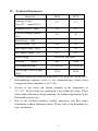
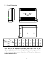
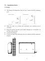
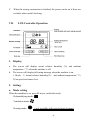
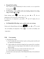
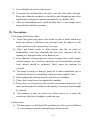
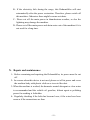
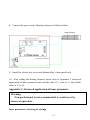
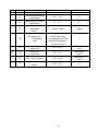
Dehumidifier User Manual
(For the series of DP40~DP70)
Content
I.
Please read immediately .......................................................................... 1
II.
Application .............................................................................................. 2
III.
Features .................................................................................................... 2
IV.
Technical Parameters ............................................................................... 3
V.
Overall Dimension ................................................................................... 4
VI.
Installation Guide..................................................................................... 5
VII. LCD Controller Operation ....................................................................... 8
VIII. Test running ........................................................................................... 10
IX.
Precautions............................................................................................. 11
X.
Repair and maintenance ......................................................................... 12
XI.
General Troubleshooting ....................................................................... 13
XII. Fault display .......................................................................................... 13
Appendix 1:Installation of Heating Element(Optional) ................................ 14
Appendix 2: Advanced application of inner parameter .................................... 17
I.
Please read immediately
Attention!
A.
B.
C.
This machine is an ordinary Dehumidifier and can never be used for
regulating other combustible gas and stale air.
The main power switch should be installed out of the reach of children to
avoid dangers caused by their playing with the switch.
If it is necessary to remove the machine shell during repair and
maintenance, please make sure that power has been cut off.
Notice for Use
A.
B.
C.
D.
E.
F.
G.
H.
The repair and maintenance must be conducted by qualified and
professional mechanics. The power supply circuit must be in line with the
local standards and please read instructions carefully.
Set appropriate humidity levels to create a comfortable environment.
Dust gauze must be cleaned regularly.
Please don’t place objects close to the air inlet or outlet which may block
the airflows.
If the electricity fails during the usage, this device will start automatically
after the power restoration.
Don’t put hands, sticks or other objects into the air inlet and outlet. Don’t
dismantle the running fans of the dust gauze.
If any abnormal situation appears, such as strange noises, smell, smoke,
electric leakage, etc., electricity should be cut off immediately and the
local dealers should be contacted. Don’t repair the machine by yourself.
The usage or storage of hair gel, paint, oil or other combustible gas or
liquid near the device is forbidden, otherwise there might be fires.
-1-
II. Application
1.
2.
Economically and efficiently dehumidify, providing you with cozy
environment.
Users can decide the machine type by referring to the technical
parameters and under the guidance of professional personnel.
Dehumidifiers of this series have been adjusted to the best of its ability
and they can work normally after the wiring and connection of the
drainage tube by professional workers under the standards.
III. Features
1.
2.
3.
4.
5.
6.
7.
8.
Efficient heat exchanger.
Sensitive and accurate computer controlling of humidity.
Environmental cooling medium R410A.
High-voltage, low-voltage and overheat protection system.
Ultra-low temperature automatic stop system.
Computer automatic defrosting.
High-quality compressor of world famous brands.
Convenient installation and easy operation.
-2-
IV. Technical Parameters
Mode Ref.
DP40
DP70
Capacity in (l/h)
(Air 30℃,Humid 70% )
2.5
3.9
Heat Recovered (kW)
2.8
4.2
Electric Heating Optional
(kw)
2.0
3.0
Rated Power (kW)
1
1.7
Rated Current (A)
4.58
7.83
Max Input Power (kW)
1.2
2.0
Max Input Current (A)
5.2
9.15
Power supply
Air flow
220-240V/1Ph/50Hz
(m³/h)
Net Dimension (mm)
Net Weight / Gross Weight
(Kgs)
800
1000
855×242×848
1155×280×848
53/68
70/86
1、The rated current with electric heating will be 8.7A for DP40, 13A for DP70.
1.
2.
3.
Dehumidifying capacity refers to the dehumidifying volume when
keeping the relative humidity at 30℃/70% .
Devices of this series can operate normally at the temperature of
5℃~38℃. Effects cannot be guaranteed if not within this range. Please
notice under different working conditions, the technical parameters of the
Dehumidifiers may vary.
Due to the technical advances, related parameters will have phase
adjustments without additional notices. Please refer to the nameplate for
more information.
-3-
H
V. Overall Dimension
B
D
A
E
G
F
C
Size(mm)
Name
A
B
C
D
E
F
G
H
DP40
286
886
200
126
613
718
36
860
DP70
286
1186
200
126
913
718
36
860
Model
Note: Above is the dimension specification figure and is only for the
reference of professional workers during installation and arrangement. Due
to the continuous improvements, the products will have phase adjustments
without additional notices.
-4-
VI. Installation Guide
1. Position:
1)
The distance of dehumidifier must be over 2 meters from the swimming
pool.
2)
Make two holes in a strong wall and knock two explosion screws
ofφ12mm.
Hang the machine from the screws firmly through two circular holes on
the back of the machine.
Connect the drainpipe.
Connect the signal lines and power line in accordance with the connection
diagram.
3)
4)
5)
A
B
C
-5-
A: signal line;
B: power line;
C: water outlet
Note: The figure above is an example and the machine installation and
arrangement is only for reference.
2. Electrical wiring diagram
Breaker/fuse
(Customer prepare)
Power Cord
Earthing
Power Supply L
220~240V
N
50Hz
Note: The Dehumidifier must have a good grounding.
3. Selection of protective device and cable specification
Type
Leakage
circuit
breaker
Fuse
Rated current
A
Rated residual
Operating current mA
A
DP40
DP70
20
30
30
30
20
30
2
Power cable (mm )
3×2.5
3×4
2
3×0.5
3×0.5
Signal line
(mm )
Note: The data above is suitable for power lines shorter than 10 meters. For
those longer than 10 meters, the wire diameters must be increased. The
maximum length of signal line is 50 meters.
-6-
4. Installation instructions and requirements
Dehumidifier must be installed by professional technicians and you as users
cannot do the installation by yourselves, in case that it may cause harm to
others and yourself or damage the machine.
A.
Installation of machine
1) Dehumidifier should be installed in a place with good ventilation.
2) The bolt (M 12) must be used to fix the machine body during the
installation. The machine can be fixed on the concrete foundation or
support, with the concrete foundation being firm and the support
being of great strength and anti-rust treatment.
3) Please notice that there will be condensate water coming out from
classis during the operation. Connect the drain port to the drainage
hole in classis and link the drainpipe to enable the smooth
flowing-out of condensate water.
B.
Electrical wiring installation
1)
2)
3)
4)
5)
Use the special power supply and the supply voltage should be in
line with the rated voltage of this product.
The Dehumidifier must have a good grounding.
Wiring must be conducted by professional technicians in accordance
with the standards of circuit diagram.
According to related technical standards for electrical equipment
specified by the nation users are located in, the electric leakage
protection device must be well set (the residual operating current
should be less than 30 mA).
Power line and signal line arrangement should be tidy and reasonable
without any interference. Given the environmental conditions
(environmental temperature, direct sunlight, rainwater, grid voltage,
cable length, etc.), the sectional area can be increased.
-7-
C.
VII.
When the wiring construction is finished, the power can be on if there are
no faults after careful checking.
LCD Controller Operation
1. Display:
a.
The screen will display actual relative humidity (%) and ambient
temperature (℃) when the machine is off.
b. The screen will display following message when the machine is on.
1. Mode; 2. Actual relative humidity(%) and ambient temperature(℃);
3.Fan speed and timer if set.
2. Setting:
a. Mode setting
When the machine is on, press M key to switch the mode:
Dehumidifying mode:
Ventilation mode:
Heating mode:
( only available with extra heating element )
-8-
Dehumidifying and Heating:
b. Set Humidity (setting range: 30%—99%)
In the dehumidifying mode
no matter machine’s on or off, every time
you press button “▲” or“▼”, the set humidity will be increased or
decreased by 1%. It’ll flash for 8 seconds and then display the actual
humidity again.
To check the set humidity, press ▲ or ▼ key under dehumidifying
mode..
c. Set Fan Speed:
When the machine’s on and in ventilation mode
switch the speed from High speed
d.
and low speed
, press “SET” to
”.
Timer Setting:
① Set timer
When the device is on, the off time can only be set as 1~12H. When the
machine is off, the on time can only be set as 1~12H.
Press button “ ”: Start the timer setting and change the timer time through
button “▲”and“▼”.
②
Press
Cancel the timer
to have the time value flashing, then press button “
timing and press “
”to exit.
-9-
”to cancel the
e. Keypad lock setting
Press “▲”and “▼”simultaneously for three seconds, so as to open/close
the keypad lock
f.
.
Set Heating ( only available with extra heating element, the setting
range is from 18℃ to 32℃.)
Under heating mode
, every time you press ▲ or ▼ , the set
temperature can be increased or decreased by 1℃.
To check the set temperature, press ▲ or ▼ and it’ll display the set
temperature.
g.
Set Humidity& Heating ( only available with extra heating)
, press ▲ or ▼ to reach
Under mode dehumidifying and heating
the set humidity & temperature. Press“
” to switch on humidity and
temperature.
VIII.
Test running
1. Checking before usage
A、Check whether the whole machine is place on the ground vertically and
be connected with drainpipes
B、Check whether the electrical wiring has been connected in accordance
with the electrical wiring diagram and whether the earth wire has been
linked reliably.
C、Check whether the power of host machine has been cut off.
D、Check whether the set humidity is appropriate.
E、
Ensure the air inlet and outlet of the Dehumidifier haven’t been blocked.
2. Test run
- 10 -
A、Users should first switch on the power.
B、To protect the dehumidifier, the device has the start delay function.
Every time when the machine is switched on, the draught fan starts first
and then the compressors operate automatically one minute later.
C、After the dehumidifier start, check whether there is any strange noise
along with the machine operation.
IX. Precautions
1. The usage should notice that:
A、Please don’t place any object close to the air inlet or outlet which may
block the airflows. Otherwise, the efficiency may be reduced or the
whole operation of the system may even stop.
B 、 Don’t put hands, sticks or other objects into the air outlet of
Dehumidifier. And don’t dismantle the fan cover, otherwise the fan
running at a high speed may cause harm to you.
C、If any abnormal situation appears, such as strange noises, smell, smoke,
electric leakage, etc., electricity should be cut off immediately and the
local dealers should be contacted. Don’t repair the machine by
yourself.
D、The usage or storage of hair gel, paint, oil or other combustible gas or
liquid near the device is forbidden, otherwise there might be fires.
E、Drip-washing the machine directly with water is forbidden.
F、Please don’t stand on or lean against the machine.
G、Please don’t use it to preserve the artworks or academic materials or for
other special purposes, otherwise the quality of restored objects might
be reduced.
H、This machine is only for indoor use. Please don’t use it under the
conditions with direct sunlight or wind and rain.
2. Safety rules
A、The main power switch should be installed out of the reach of children
to avoid dangers caused by their playing with the switch.
- 11 -
B、If the electricity fails during the usage, this Dehumidifier will start
automatically after the power restoration. Therefore, please switch off
this machine. Otherwise there might be some accidents.
C、Please cut off the main power in thunderstorm weather, or else the
lightning may damage the machine.
D、Please cut off the main power and drain water out of the machine if it is
not used for a long time.
X. Repair and maintenance
1、Before examining and repairing the Dehumidifier, its power must be cut
off.
2、In seasons when this device is not used, please cut off its power and cover
the machine body with plastic cloth so as to avoid the dust.
3、When the machine is washed, the domestic neutral detergent or clear water
is recommended and the volatile oil, gasoline, diluent agent or polishing
power for washing is forbidden.
4、Regularly checking if the bolts has become loose, if the wires have been
worn or if the connections are firm.
- 12 -
XI. General Troubleshooting
fault
Cause
Power cut
Power switch not on
Handling method
Waiting for power restoration
Switch on the power
Check the problem and
Fuse burnt out
Not operating
replace the fuse
Check the problem and
Leakage circuit breaker
switch on the leakage circuit
being off
breaker
If the problems above cannot be solved, please contact professional
workers and inform them of the product type and details about faults.
Attention! Never dismantle the machine and repair it by yourself so
as to avoid any danger.
XII.
Fault display
Protection/fault
wired controller display
- 13 -
Room temperature sensor fault
E1
Coil temperature sensor fault
E2
Humidity sensor fault
E3
Outlet temperature sensor fault
EF
Return air temperature sensor fault
EH
High-pressure protection
E4
Low-pressure protection
E5
Air outlet overheat protection
E7
Communication fault
EE
Overheat Protection(only available with
heating element)
EC
Appendix 1:Installation of Heating Element(Optional)
Warning:
The heating element of dehumidifier must be installed and trial
by qualified electrician.
A、Heating element’s break down
1)Heating Element: 1pc
2). Screws: 4pcs
- 14 -
B、Steps
1、Turn off the machine and shut off the power. Use a Phillips screwdriver to
takeoff the 8pcs screws from the side panels. Dismantle the front panel;
2、Take off the 2pcs screws on the left side of electric element, take off the
bottom strip.
3、Put the heating element on the top of the dehumidifier, make sure the four
holes of heating element in the right position against the four holes of top
panel.
- 15 -
4、Use a Phillips screwdriver to fix the two screws on the right side.
5、Install the bottom strip back and fix the two screws in the left side.
6、Open the cover of electric box,and drill the signal cable & power cord
through the holes and pull it to the electric box.
7、Unpin the wire of P4 port in PC board, and plug the signal cable to it.
- 16 -
8、Connect the power cord of heating element as bellowed chart.
9、Install the electric box cover and dehumidifier’s front panel back.
10、After adding the heating element, please refer to Appendix 2 Advanced
application of inner parameter and reset the code C1’s value to 1 ( the default
value of C1 is 0).
Appendix 2: Advanced application of inner parameter
Warning:
Non-professional is not recommended to avoid error by
incorrect operation.
Inner parameter’s checking & setting:
- 17 -
Press button “SET” for three seconds and enter the menu of parameter
checking & setting.
The smaller 8 displays codes and the bigger 8 displays the relative parameters.
A. To check the inner parameters:
When machine’s on, press button “Set” for 3 seconds. And then press
button “▲”and ▼” to check the code and relative parameter.
B. To set the inner parameters:
When machine’s off, press button “Set” for 3 seconds; Press “▲”
and“▼”to check each code & parameter, press “Set”and the code will
flash, you can press “▲”and“▼” to reset the parameter value. After, press
“Set” to confirm. And press”
”or“
”to exit。
The parameter table is as follows:
Parameter
meaning
Parameter specification
Default value
1
Param
eter
code
C1
Heating or not
0 no/1 yes
2
C2
Coil temperature
-20℃~99℃
3
C3
Humidity
-5% ~ 5%
0
Measured
value
0%
N
O.
- 18 -
4
C4
5
C5
6
C6
7
C7
compensation
Defrosting cycle
Defrosting starting
temperature
Defrosting closing
temperature
Maximum
defrosting
time
Working state
of draught
fan
20Min~90Min
40Min
-10℃~10℃
-1℃
0℃~15℃
8℃
2Min~12Min
8Min
0 reaching the set value
and the fan stops/
1 reaching the set value
and the fan operates
with low wind
1
8
C8
9
C9
10
CA
11
Cb
EXV step number
100~500P
12
CC
Target superheat
degree
-20℃~20℃
Air outlet
temperature
Return air
temperature
-20℃~99℃
-20℃~99℃
- 19 -
Measured
value
Measured
value
Measured
value
5℃
Version: H64-20130719