1
ER3000 Electronic
Pressure Controller
User Manual
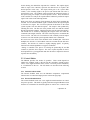
PRODUCT WARRANTY
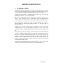
Tescom ("Tescom") warrants to the party who purchases products for initial use
directly from Tescom, its affiliates or authorized distributors or representatives
("Initial Purchaser") that products manufactured and sold by its Industrial Controls
Group (“IC”) are free from defects in materials and workmanship under normal use
and service for a period of 365 days from the date of delivery of the products
("Warranty Period"). This warranty applies only to the Initial Purchaser. This
warranty is not transferable to subsequent purchasers or users of the products.
During the Warranty Period, Tescom will, in its sole discretion, repair or replace, free
of charge at its factory in Minnesota, any product or part thereof that is found by
Tescom, after reasonable notification by the Initial Purchaser, to have been defective
in materials or workmanship. The Initial Purchaser must pay all shipping costs for
warranty service and is responsible for risk of loss or damage of products during
shipment. Tescom does not warrant, and will not pay for, any repairs or replacement
made during the Warranty Period by anyone other than personnel authorized by
Tescom or its IC Group to make such repairs or replacement.
THE ABOVE WARRANTY IS IN LIEU OF ALL OTHER WARRANTIES.
TESCOM AND ITS IC GROUP MAKE NO OTHER EXPRESS OR IMPLIED
WARRANTY, AND IN PARTICULAR AND WITHOUT LIMITATION MAKE
NO IMPLIED WARRANTIES OF MERCHANTABILITY OR FITNESS FOR
PARTICULAR PURPOSE. The Initial Purchaser's only remedy under this warranty
is repair or replacement of the products during the Warranty Period. This warranty
does not apply to any product which has been damaged by accident, abuse, misuse,
modification or lack of proper maintenance. NEITHER TESCOM, NOR ITS IC
GROUP WILL BE LIABLE FOR ANY CONSEQUENTIAL, SPECIAL,
INCIDENTAL OR INDIRECT DAMAGES, INCLUDING WITHOUT
LIMITATION, LOST PROFITS.
INDUSTRIAL CONTROLS
12616 Industrial Boulevard
Elk River, Minnesota 55330-2491
1-800-447-1250 (763) 241-3238
FAX (763) 241-3224
e-mail: [email protected]
www.tescom.com
Windows® 3.1, Windows® 95, Windows® NT, DOS, and Visual Basic™ are trademarks of Microsoft
Corporation. LabVIEW™ and LabWindows®/CVI are trademarks of National Instruments
Installation & Operation Precautions
TESCOM Industrial Controls
INTRODUCTION
Prior to installing or operating any equipment, read and follow all the information listed. Improper
application and operation can result in damage to equipment or severe personal injury.
All possible hazards and precautionary measures cannot be covered here. It is recommended that prior
to using this equipment, you fully understand and comply with existing safety regulations.
OXYGEN SERVICE
Specification of the materials in regulators used for oxygen service is the USER’S RESPONSIBILITY.
Cleaning for oxygen service to 3000 PSIG is supplied standard by Tescom at no additional cost for
mechanical regulators. Cleaning for service above 3000 PSIG may be contracted through an outside
source.
COMPATIBILITY
Tescom may suggest material for use with specific media upon request. Suggestions are based on
technical compatibility resources through associations and manufacturers. Tescom does NOT
guarantee materials to be compatible with specific media - THIS IS THE RESPONSIBILITY OF THE
USER! Users must test under operating conditions to determine suitability of materials in an
application.
PRESSURE RATING
Verify the designed pressure rating of the equipment. Check supply lines, fittings, connections, filters,
valves and gauges. All must be adequate for the supply and operating pressure.
RELIEF PROTECTION
A regulator is not intended to be used as a shut-off device. A pressure relief device should be installed
downstream of the regulator to protect the process equipment in the case of a rise in operating pressure.
When the regulator is not in use, the supply pressure should be closed.
FILTRATION
An auxiliary upstream filter is recommended for use in all media. Gaseous media should be free of
excessive moisture to prevent icing of the equipment.
MAINTENANCE
Periodic inspection and scheduled maintenance of your equipment is essential for continued safe and
satisfactory operation. The frequency of servicing will depend on the application.
REPAIR SERVICE
Any equipment in need of service should be returned to your equipment supplier for evaluation and
prompt service. If repairable, your equipment will be restored to the original factory performance
specifications. A flat fee repair charge has been established for each standard model and the original
equipment warranty will be reinstated after a complete overhaul.
ASSEMBLY/INSTALLATION DRAWINGS & BILLS OF MATERIAL
Drawings and parts lists for your product may be obtained by calling 1(800) 447-1204. Tescom
will provide these by fax or mail. Your local distributor can provide additional assistance.
TABLE OF CONTENTS
1.
INTRODUCTION ---------------------------------------------------------------- 7
2.
SPECIFICATIONS -------------------------------------------------------------- 8
2.1
2.2
2.3
2.4
2.5
2.6
2.7
2.8
2.9
2.10
2.11
2.12
2.13
2.14
2.15
2.16
ENCLOSURE ---------------------------------------------------------------------- 8
MEDIA---------------------------------------------------------------------------- 8
INLET PRESSURE----------------------------------------------------------------- 8
ENVIRONMENT ------------------------------------------------------------------- 8
FLOW RATE ---------------------------------------------------------------------- 8
POWER REQUIREMENT ---------------------------------------------------------- 8
RS485 COMMUNICATION INTERFACE------------------------------------------ 8
ACCURACY ----------------------------------------------------------------------- 9
RESPONSE TIME ----------------------------------------------------------------- 9
PORTS ---------------------------------------------------------------------------- 9
WEIGHT -------------------------------------------------------------------------- 9
EXTERNAL ANALOG INPUT IMPEDANCE ---------------------------------------- 9
DIGITAL OUTPUTS --------------------------------------------------------------- 9
DIGITAL INPUTS ----------------------------------------------------------------- 9
ANALOG OUTPUT ---------------------------------------------------------------- 9
SENSOR UPDATE RATE ---------------------------------------------------------- 9
3.
ER3000 PART NUMBERING SYSTEM ------------------------------------10
4.
INSTALLATION ----------------------------------------------------------------11
4.1
4.2
4.3
4.4
4.4.1
4.4.2
4.4.3
4.4.4
4.4.5
4.4.6
4.4.7
4.4.8
4.4.9
4.5
4.5.1
4.5.2
4.5.3
4.5.4
4.5.5
INTERFACE CABLE ASSEMBLIES -----------------------------------------------11
VOLTAGE/CURRENT SELECT JUMPERS ----------------------------------------12
BASIC ER3000 TO PC WIRING------------------------------------------------13
SETTING UP A TYPICAL ER3000 PRESSURE CONTROL SYSTEM--------------14
Plumb the External Regulator and Transducer-----------------------14
Mount the ER3000 --------------------------------------------------------15
Connect the Power Supply -----------------------------------------------15
Connect RS485 Interface Connections---------------------------------15
Install the “ER3000 (CVI)” Windows Program ----------------------15
Communicate to the ER3000, using the ER3000 (CVI) Windows Program-15
Connect Transducer Wiring ---------------------------------------------16
Connect Pressure to the System -----------------------------------------16
Tune the System -----------------------------------------------------------16
ADDITIONS AND VARIATIONS TO THE TYPICAL SYSTEM -----------------------17
Transducer Wiring Configurations-------------------------------------17
Analog Setpoint Source --------------------------------------------------19
Monitor the Feedback Signal--------------------------------------------21
Profile Control / Digital Inputs -----------------------------------------23
Switch Feedback Control to a Second Feedback Source ------------24
4.5.6
4.5.7
4.5.8
4.5.9
5.
OPERATION---------------------------------------------------------------------28
5.1
5.1.1
5.2
5.2.1
5.2.2
5.2.3
5.2.4
5.3
5.4
5.5
5.6
5.6.1
6.
TYPICAL APPLICATION TO TUNE -----------------------------------------------32
TUNE THE TYPICAL APPLICATION ---------------------------------------------34
CALIBRATION------------------------------------------------------------------39
7.1
8.
ZERO/SPAN ----------------------------------------------------------------------39
SOFTWARE PROGRAMS ----------------------------------------------------40
8.1
8.2
8.3
8.3.1
8.3.2
8.3.3
8.4
8.4.1
8.4.2
8.4.3
8.4.4
8.4.5
8.4.6
9.
9.1
9.2
9.3
9.4
THEORY OF OPERATION --------------------------------------------------------28
PID Control----------------------------------------------------------------28
CONTROL MODES --------------------------------------------------------------29
Internal Feedback Mode -------------------------------------------------29
External Feedback Mode-------------------------------------------------29
Cascade Loop Mode ------------------------------------------------------30
Manual Mode--------------------------------------------------------------30
SETPOINT SOURCES -------------------------------------------------------------30
FAILSAFE LIMITS ---------------------------------------------------------------31
LEDS----------------------------------------------------------------------------31
RS485 COMMUNICATION ------------------------------------------------------31
Protocol --------------------------------------------------------------------31
TUNING PROCEDURE -------------------------------------------------------32
6.1
6.2
7.
Monitor Analog Signals--------------------------------------------------24
Networking ER3000’s ----------------------------------------------------25
Digital Outputs ------------------------------------------------------------26
Monitor Internal Sensor using the Analog Output -------------------27
WINDOWS TUNE PROGRAM ----------------------------------------------------40
WINDOWS EXAMPLE PROGRAMS-----------------------------------------------40
TESCOM PROTOCOL (PROVIDES CUSTOM SOFTWARE SUPPORT) ------------40
DOS Library ---------------------------------------------------------------41
Windows DLL--------------------------------------------------------------41
Macintosh Custom Software---------------------------------------------42
DOS PROGRAMS ---------------------------------------------------------------42
Tune-------------------------------------------------------------------------42
Ertalk -----------------------------------------------------------------------42
Profile-----------------------------------------------------------------------42
Profile2 ---------------------------------------------------------------------42
Data_log -------------------------------------------------------------------43
Test_pr----------------------------------------------------------------------43
ER3000 INTERNAL VARIABLES-------------------------------------------44
SETPOINT AND FEEDBACK VARIABLES ----------------------------------------44
CONFIGURATION VARIABLES ---------------------------------------------------44
INNER LOOP TUNING VARIABLES ----------------------------------------------45
OUTER LOOP TUNING VARIABLES ---------------------------------------------45
9.5
9.6
9.7
9.8
9.9
9.10
9.11
9.12
9.13
9.14
ANALOG INPUT VARIABLES-----------------------------------------------------46
PRESSURE PROFILE CONTROL VARIABLES ------------------------------------46
SINGLE “PUFF” SOLENOID CONTROL VARIABLE ----------------------------47
PULSE MODE VARIABLES ------------------------------------------------------47
SCALING VARIABLES ------------------------------------------------------------47
ANALOG AND DIGITAL OUTPUT VARIABLES -----------------------------------48
PWM CONTROL VARIABLES ---------------------------------------------------48
GAIN/OFFSET VARIABLES ------------------------------------------------------49
FAILSAFE VARIABLES -----------------------------------------------------------49
TABLE OF ALL ER3000 INTERNAL VARIABLES --------------------------------51
10.
TROUBLESHOOTING-----------------------------------------------------54
10.1
LED INDICATORS --------------------------------------------------------------54
10.2
THIRD PARTY RS232/RS485 CONVERTERS ----------------------------------55
10.3
ER3000 POWER-UP TEST, USING LED INDICATORS ------------------------55
10.4
ER3000 DATA COMMUNICATIONS TEST, USING LED INDICATORS --------55
10.5
PRESSURE CONTROL PROBLEMS ----------------------------------------------57
10.6
ACCEPTABLE RESISTANCE VALUES --------------------------------------------57
10.6.1
ER3000 RS485 Interface ---------------------------------------------57
10.6.2
Converter RS485 Interface -------------------------------------------57
10.7
LEAK TEST ----------------------------------------------------------------------58
10.7.1
Windows ER3000 Program ------------------------------------------58
10.7.2
DOS Tune Program ---------------------------------------------------58
11.
ER3000 ACCESSORIES ---------------------------------------------------60
12.
MECHANICAL DIMENSIONS OF ER3000---------------------------61
Table Of Figures
Figure 1: Voltage/Current Select Jumpers ......................................................... 12
Figure 2: ER3000 Basic Wiring Diagram ......................................................... 13
Figure 3: ER3000 Typical System Wiring Diagram ......................................... 14
Figure 4: Three-Wire External Feedback Cabling............................................ 17
Figure 5: Four-Wire External Feedback Cabling ............................................. 18
Figure 6: Passive PC or PLC D/A Card Analog Setpoint (4-20mA)................ 19
Figure 7: Active PC or PLC D/A Card Analog Setpoint (4-20mA, 1-5V, 0-10V) ........ 19
Figure 8: Potentiometer Analog Setpoint .......................................................... 20
Figure 9: Current/Voltage Analog Setpoint ...................................................... 20
Figure 10: Monitor 4-20mA External Feedback (Floating Input)..................... 21
Figure 11: Monitor 4-20mA External Feedback (Ground Referenced Input).. 21
Figure 12: Monitor voltage produced by 4-20 mAmp External Feedback....... 22
Figure 13: Monitor 1-5V/0-10V External Feedback ......................................... 22
Figure 14: External Profile Control .................................................................. 23
Figure 15: Switch between two External Feedback Sources............................. 24
Figure 16: Networking/Daisychaining ER3000’s ............................................. 25
Figure 17: ER3000 Digital Outputs .................................................................. 26
Figure 18: Monitor Internal Sensor (4-20mA wiring) ...................................... 27
Figure 19: Monitor Internal Sensor (0-10V wiring) ......................................... 27
Figure 20: Regulator and ER3000 Internal Operation .................................... 32
Figure 21: LED Locations ................................................................................. 54
ER3000 USER MANUAL
1. INTRODUCTION
The ER3000 (Electronic Regulator) is a versatile 0 to 100 psi pressure controller.
It can be used in conjunction with any pneumatically actuated regulator or valve
to control pressure from subatmosphere to 20,000 psi with Cv’s of up to 45.
Setpoints can be provided via an analog input (4-20mA, 1-5V, or 0-10V), the
digital RS485 interface, or a downloaded profile.
The RS485 interface makes pressure control by a computer easier than ever
before.
The controller can be wired quickly into the standard serial
communication port found on any PC using a low-cost RS232 to RS485 adapter.
This communication channel also provides for the programming of a number of
internal parameters, including PID tuning variables, zero and span, mode of
operation, limits, etc.
Feedback can be derived either from the ER3000’s internal temperature
compensated sensor or an external transducer (4-20mA, 1-5V, or 0-10V). This
second option allows for positioning the sensor downstream in the actual process
line.
Four modes of operation are available. Internal feedback mode (which makes the
controller an I/P when analog setpoints are used) and uses the internal sensor as
the source of feedback. External feedback mode uses an external sensor as the
feedback. Cascade mode creates a loop within a loop; the inner loop uses the
internal sensor for feedback and the outer loop uses the external transducer for
feedback. Manual mode allows for direct control of the solenoid valves (useful
for troubleshooting the system).
In summary, the ER3000 electronic pressure regulator is easy to get up and
running, yet offers the flexibility required by the most demanding user.
1. Introduction 7
2. SPECIFICATIONS
2.1 Enclosure
NEMA 4X.
To prevent any interference from electromagnetic radiation, use rigid metal conduit
to enclose the wiring entering the ER3000. Two 1/2NPT wire ports have been
provided for this purpose. If unused, properly seal with a metal plug.
2.2 Media
The preferred media is clean, dry instrument grade air or nitrogen. Use
of an in-line 40-micron filter is highly recommended to prevent damage
to the solenoid valves.
2.3 Inlet Pressure
Minimum:
Outlet pressure + 1 PSIG.
Maximum:
120 PSIG.
Typical:
110 PSIG.
Note: Response time is affected by input pressure.
2.4 Environment
Temperature:
Pressure:
Humidity:
-30ºC to 75°C (Dry nitrogen supply gas).
-20ºC to 60ºC (KEMA Explosion Proof Versions M & N)
5ºC to 75°C (Shop air).
28 - 32 inches Hg
To 100% R.H (non-condensing) @ 0°C to 75ºC.
2.5 Flow Rate
Cv:
0.01.
Note: The flow rate can be increased using a booster regulator.
2.6 Power Requirement
Voltage:
Current:
24V (22V to 28V)
340mA Max, 180mA Nominal
2.7 RS485 Communication Interface
Networking:
Cable length:
Baud rate:
8 ER3000 User Manual
Up to 32 controllers on one network.
4000 ft. Max.
9600
2.8 Accuracy
Room temp.:
Temp. effects:
0.1% of span max
0.002%/°F of span max.
2.9 Response Time
Rise Time:
257ms. - 10 psi to 90 psi
Fall Time:
552ms. - 90 psi to 10 psi
Note: Step response into dead-end system (1 cubic inch volume).
2.10 Ports
Conduit:
Pneumatic:
1/2” NPT
1/8” NPT - Inlet, exhaust and gauge ports.
1/4” NPT - Controlled outlet port.
2.11 Weight
34.8 oz. (1.0 kg).
2.12 External Analog Input Impedance
4-20mA:250Ω
1-5V:
0-10V:
220KΩ - Single Input Pin to Gnd.
1.7MΩ - Differential Input
100KΩ
2.13 Digital Outputs
Current:
Voltage:
Type:
50 mA Continuous, 100 mA Instantaneous
5V - 28V
Open collector, grounded emitter
2.14 Digital Inputs
Voltage Range/Input Impedance:
4-20 mA:
250Ω
1-5V:
220KΩ - Single Input Pin to Gnd.
1.7MΩ - Differential Input
0-10V:
100KΩ
Type:
Level Sensitive
2.15 Analog Output
4-20mA:0.5% Accuracy
2.16 Sensor Update Rate
25ms:
Rate of sensor reading and processing task
2. Specifications 9
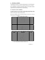
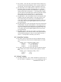
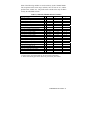
3. ER3000 PART NUMBERING SYSTEM
Standard features:
RS485 communications included.
1/8” inlet and exhaust ports, 1/4” controlled output port.
Maximum inlet pressure = 120 psig.
0 to 100 psig internal sensor.
Windows/DOS software package included.
24 VDC power required.
As the table below indicates, other sensor ranges are available. Please consult the
factory for special modifications or requirements.
Cv
Configuration
ER3 XX X X X - X
Current/Voltage
I…4-20 mA/1-5 VDC
V…0-10 VDC
1…Standard,
Cv=0.01
2…Low flow
(Cv=0.001)
4…High flow
(Cv=0.1)
Base Style
00…Standard
02…Integrated with
26-1000 and 269-529
04…OEM style (no
cover)
10…Integrated with
44-4000
11…Integrated with
44-5200
10 ER3000 User Manual
Internal Sensor Configuration
Board Configuration
0…0-100 psig, 0.1% accuracy
2…0-50 psia, 0.1% accuracy
3…0-150 psia, 0.1% accuracy
4 0-5 psig, 0.25% accuracy
S…Standard
(setpoint/feedback)
F…2 extra analog
inputs/outputs
E…Explosion proof
G…Combines F & E
M…KEMA explosion proof
N…Combines F & M
4. INSTALLATION
The ER3000 has a number of variations and wiring options. The following pages
of the installation section detail a typical installation and many of those options.
Note: Installation of explosion proof models shall be in accordance with the
specifications of the standards shown on the metal tag.
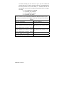
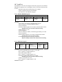
4.1 Interface Cable Assemblies
The following tables give the complete wiring layout of the ER3000 wiring
assemblies, which are connected to the J3 and J4 terminal blocks. Refer to the
tables to ensure proper wiring of external devices.
Note: The (+) and the (-) refer to the differential inputs. Both must be connected
for the system to work properly.
J3 Pins
1
2
3
4
5
6
7
8
9
10
11*
12
Table 1: Main Cable Assembly
Description
+Setpoint Input.
-Setpoint Input.
+Feedback Input.
-Feedback Input.
-RS485 Network connection.
+RS485 Network connection.
+ 24 Volt DC Power.
24 Volt Return, (Power Ground).
+5 Volt output (5mA Max.).
Analog Signal Ground.
Analog Signal Output.
Analog Signal Ground.
Color
Brown
Red
Orange
Yellow
Green
Blue
Violet
Gray
White
Black
Pink
Tan
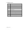
Table 2: Auxiliary Cable Assembly (ER3000F and ER3000G models)
J4 Pins
Description
Color
1
+Aux. Input #1.
Brown
2
-Aux. Input #1.
Red
3
+Aux. Input #2.
Orange
4
-Aux. Input #2.
Yellow
5
Analog Signal Ground.
Green
6
Digital Output Ground.
Black
7
Digital Output #1.
Blue
8
Digital Output #2.
White
* Active in ER3000F and ER3000G Models only.
4. Installation 11
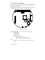
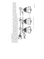
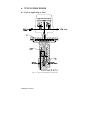
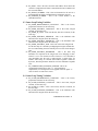
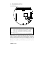
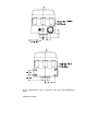
4.2 Voltage/Current Select Jumpers
Figure 1 shows the J5 voltage/current select jumpers location on the ER3000.
Use them to select between 4-20mA and 1-5V. The 0-10V models of the
ER3000 do not have the jumpers.
The jumper on the bottom board is for factory installation of the embedded
software only and the jumper should not be installed for normal operation.
1 2 3 4 5 6 7 8 9 101112 1 2 3 4 5 6 7 8
J3
J4
J5
1
2 3
4
LED3
LED2
LED1
Figure 1: Voltage/Current Select Jumpers
Jumper J5 (top board) - Voltage/Current Select (not on 0-10V models)
1: Analog Setpoint
2: External Feedback
3: Auxiliary input #1
4: Auxiliary input #2
For all the above jumper positions:
Jumper not installed - configured for 1-5V input.
Jumper installed - configured for 4-20mA input.
LED’s
Refer to Section 10.1, LED Indicators, for an explanation of the LED
indicators.
12 ER3000 User Manual
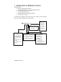
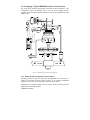
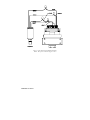
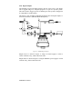
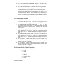
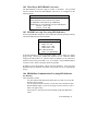
4.3 Basic ER3000 to PC Wiring
The necessary wiring for the ER3000 communicating to a PC is shown in Figure
2. A PC is typically used to communicate to the ER3000 digitally, but any
device capable of the interface protocol could be used, such as a PLC.
Figure 2: ER3000 Basic Wiring Diagram
4. Installation 13
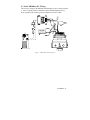
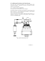
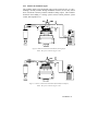
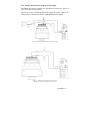
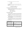
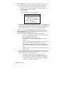
4.4 Setting up a Typical ER3000 Pressure Control System
One of the most commonly used modes of operation is shown in Figure 3. The
configuration shows the ER3000 with a 24 Volt power supply, pressure
regulator, 4-20mA transducer, RS232/RS485 converter, and an optional 25-9 pin
adapter cable.
Figure 3: ER3000 Typical System Wiring Diagram
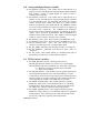
4.4.1 Plumb the External Regulator and Transducer
If higher pressures or flows are required by the application or it is necessary to
isolate the controller from the process media, an air actuated mechanical
regulator can be used to boost the output and/or provide isolation.
Additionally, an external transducer may be used to sense the process pressure
supplied by the external regulator.
14 ER3000 User Manual
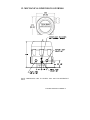
4.4.2 Mount the ER3000
Four 8-32 UNC screw holes are provided for the physical mounting of the
ER3000. For details, reference mechanical drawings at the back of the manual.
4.4.3 Connect the Power Supply
Connect a 24 Volt power supply to the ER3000, as shown in Figure 2.
Power up the ER3000.
Visually check the LED indicators to ensure that power is supplied to the
ER3000. The red LED, LED1, on the top board should be ON indicating power
applied and the red LED, LED1, on the bottom board should be blinking
indicating the embedded software is running.
Power down the ER3000.
4.4.4 Connect RS485 Interface Connections
Connect the ER3000 to the Tescom RS232/RS485 converter, as shown in Figure
2. Consult our Troubleshooting section if using a third party converter, not all
converters are capable of the mode of operation expected by our software.
Connect the RS485 converter directly to a COMM port (default=COM2) of the
computer, if necessary include the 25 to 9 pin adapter cable.
4.4.5 Install the “ER3000 (CVI)” Windows Program
Insert the “ER3000 User Software” CD into your PC and the install program
should start automatically. If it does not, choose and run the “autorun”
executable on the CD. Click on the INSTALL button in the “CD Menuing
System” menu to get to the “Installation Menu”. From the “Installation Menu”,
chick on the Windows Tune (32 BIT) button. Follow the on-screen instructions
during the installation process. The installation will automatically create the
directory ER3000 and install the Windows Tune program, including support files
(e.g. TESCOM.DLL).
The Windows program contains a complete online help manual and a manual.rtf
file of all the online help pages that may be easily printed out.
4.4.6 Communicate to the ER3000, using the ER3000 (CVI) Windows
Program
Power up the ER3000.
Execute the ER3000 (CVI) program. The program is executed by pressing the
Start button, choosing the Programs menu, choosing the ER3000 (CVI) folder,
and then selecting the ER3000 (CVI) program. If an error occurs, go to the
Troubleshooting section.
Power down the ER3000.
4. Installation 15
4.4.7 Connect Transducer Wiring
If the downstream process pressure regulation is required by the application, a
pressure transducer can be used to provide a 4-20mA, 1-5V, or 0-10V feedback
signal. Figure 3 shows wiring for a 2-wire 4-20mA transducer. The wiring of
three and four wire transducers are shown in section 4.5.1, Transducer Wiring
Configurations.
Check to ensure that the external feedback voltage/current select jumper is
installed for 4-20mA or removed for 1-5V operation. There is no jumper on the
0-10V external feedback ER3000 models.
4.4.8 Connect Pressure to the System
Figure 3 illustrates the typical pressure connections for the ER3000. The
ER3000 inlet pressure is the supply pressure (max 120 psi). The exhaust port on
the ER3000 is used for venting when a pressure reduction is required. The inlet
pressure to the regulator depends on the capability of the regulator and the
system requirements. The output pressure is the regulated pressure being
supplied to the process.
The gauge port can have a pressure gauge attached or simply plugged. If desired,
the gauge port can be used as the output (the normal output port must then be
plugged).
4.4.9 Tune the System
The system should now be fully installed. The system performance can be
checked using the Windows ER3000 (CVI) program or the DOS Tune program
provided. The tuning parameters can be updated using these programs to alter
the ER3000 and system performance. Refer to the Tuning Procedure section for
details on tuning the pressure control system.
16 ER3000 User Manual
4.5 Additions and Variations to the Typical System
This section shows variations and additions to the Typical ER3000 control
system shown in Figure 3. Alternatively, use Figure 2 as a baseline for systems
without an external transducer.
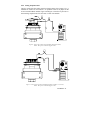
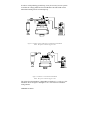
4.5.1 Transducer Wiring Configurations
The wiring for the two-wire transducer is shown in Figure 3.
The wiring for the three wire and four wire transducers are shown in Figure 4 and
Figure 5 respectively. Connect the ER3000 to the transducer, or other feedback
source, as shown in the respective diagrams.
Check to ensure that the external feedback voltage/current select jumper, J5:2, is
installed for 4-20mAmp or removed for 1-5 Volt operation. There is no jumper
on the 0-10 Volt ER3000 models.
Figure 4: Three-Wire External Feedback Cabling
NOTE: Wire power as shown in figures 2 & 3
4. Installation 17
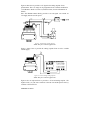
Figure 5: Four-Wire External Feedback Cabling
NOTE: Wire power as shown in figures 2 & 3
18 ER3000 User Manual
4.5.2 Analog Setpoint Source
Check to ensure that the analog setpoint voltage/current select jumper, J5:1, is
installed for 4-20mA or removed for 1-5V operation. There is no jumper on the
0-10V external feedback models. Figure 6 and Figure 7 show how to provide a 420mA analog setpoint from a PC D/A card or a PLC D/A module.
Figure 6: Passive PC or PLC D/A Card Analog Setpoint (4-20mA)
NOTE: Wire power as shown in figures 2 & 3
Figure 7: Active PC or PLC D/A Card Analog Setpoint (4-20mA, 1-5V, 0-10V)
NOTE: Wire power as shown in figures 2 & 3
4. Installation 19
Figure 8 shows how to provide a 0-5V signal to the analog setpoint from a
potentiometer. The 0-1V range can be programmed to be a failsafe condition for
1-5V ER3000’s. Refer to section 5.4, Failsafe Limits, for more information on
failsafe.
Note: The ER3000 cannot directly provide a 0-10 volt signal. An external 10volt supply must be used for power.
Figure 8: Potentiometer Analog Setpoint
NOTE: Wire power as shown in figures 2 & 3
Figure 9 shows how to provide the analog setpoint from an active variable
current supply.
Figure 9: Current/Voltage Analog Setpoint
NOTE: Wire power as shown in figures 2 & 3
Figure 9 also can represent how to provide a 1-5V/0-10V analog setpoint. The
negative lead (-) of your source connects to the red wire and the positive lead (+)
connects to the brown wire.
20 ER3000 User Manual
4.5.3 Monitor the Feedback Signal
The feedback signal can be monitored using an A/D card in the PC, or a PLC.
Although, currently available through the RS485 interface, the user may find it
more convenient to directly read the transducer analog output. This would be
beneficial when adding to existing system software which performs system
control, data acquisition, etc.
Figure 10: Monitor 4-20mA External Feedback (Floating Input)
NOTE: Wire power as shown in figures 2 & 3
Figure 11: Monitor 4-20mA External Feedback (Ground Referenced Input)
NOTE: Wire power as shown in figures 2 & 3
4. Installation 21
In order to avoid producing ground loops, it may be necessary in some systems
to monitor the voltage produced across the ER3000’s internal 250 Ω resistor
rather than breaking into the 4-20 mAmp loop.
Figure 12: Monitor voltage produced by 4-20 mAmp External Feedback
NOTE: Wire power as shown in figures 2 & 3
Figure 13: Monitor 1-5V/0-10V External Feedback
NOTE: Wire power as shown in figures 2 & 3
The wiring from the transducer is dependant on whether it is a 3-wire or 4-wire
transducer. Refer to Figure 4 and Figure 5 for 3-wire and 4-wire transducer
wiring schemes.
22 ER3000 User Manual
4.5.4 Profile Control / Digital Inputs
This feature is only available on models that have the extra analog inputs, as
referenced in section 3 (ER3000 Model Descriptions).
Figure 14 shows a simple wiring method of controlling a profile, without the need
for a computer. Once the profile is downloaded into the ER3000, it can be
started or stopped with a toggle switch. The Digital Input pushbutton may be
used if the “Digital Input” function has been used within the profile. This allows
an operator the flexibility to wait until an event has occurred like changing to the
next device.
An additional feature, necessary for some demanding applications, is provided
for by the Profile Start/Stop and Digital Input signals, which are the Extra
Analog Input 1 and Extra Analog Input 2 inputs of the ER3000. This feature is
the ability to adjust the toggle level (or trip point) of the analog input where it
switches between a logical 0 and a logical 1. The ER3000 toggle variables
enable this feature and are described in section 9.5, Analog Input Variables. For
example, this feature allows connecting a pressure transducer to the Digital Input
and waiting for a specific pressure before continuing on in the pressure profile.
Figure 14: External Profile Control
NOTE: Wire power as shown in figures 2 & 3
(J5 jumpers 3 and 4 must be removed, refer to Figure 1)
4. Installation 23
4.5.5 Switch Feedback Control to a Second Feedback Source
The feedback source can be easily switched between two feedback sources by
writing to variable 87 (ID_EXT_FEEDBACK_SOURCE) in the ER3000. This
may be quite beneficial if trying to control at two very different pressures, e.g. 80
psi and 8000 psi. Transducer 1 could be a 10,000 psi transducer and Transducer
2 could be a 100 psi transducer.
This feature is only available on ER3000 models that have the extra analog
inputs, as referenced in Section 3 (ER3000 Model Description).
Figure 15: Switch between two External Feedback Sources
NOTE: Wire power as shown in figures 2 & 3
4.5.6 Monitor Analog Signals
The ER3000 can monitor a number of analog signals. This is quite useful in data
acquisition systems to perform trend analysis on the system. Figure 15 shows
two transducers (e.g. with outputs P1 and P2) that can be continuously monitored
by a PC program. All of the ER3000 models can monitor two analog signals, the
analog setpoint and external feedback. Some ER3000 series models, as
referenced in Section 3 (ER3000 Model Description), can monitor two additional
analog signals; the extra input 1 and extra input 2 signals.
Monitoring Extra Input 2 does necessitate the knowledge that this input doubles
as the Profile Start/Stop input. The toggle level of Extra Input 2 should be set to
its maximum value, 4095, if you do not want the pressure profile to start running.
This is simply done by adjusting variable 86 (ID_AD_EXTRA2_TOGGLE)
described in section 9.5 (Analog Input Variables).
24 ER3000 User Manual
Figure 16: Networking/Daisychaining ER3000’s
4. Installation 25
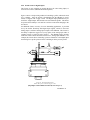
4.5.7 Networking ER3000’s
Up to 32 ER3000’s can be networked together, daisychained, as shown in Figure 16. The ER3000’s must be set up to different node
addresses before being networked together and powered-up. All ER3000’s are factory set to node address 250, therefore the address
must be changed to allow them to all communicate on the network. Changing the node address is accomplished by wiring an ER3000 as
shown in Figure 2 and running the Windows ER3000 program. Once communicating to the ER3000 change the Node Number field in
the Miscellaneous Window from 250 to the desired node address. Repeat this process for all nodes.
Note: Power supply must be able to provide 300mA to each ER3000 in the network.
4.5.8 Digital Outputs
The ER3000’s can provide digital outputs to the rest of the system. The outputs
can be toggled using a PC computer program or as part of a pressure profile.
This can be used to trigger a process in another part of the system or simply turn
on a light bulb or sound an alarm.
This feature is only available on ER3000 models that have the digital outputs, as
referenced in Section 3 (ER3000 Model Description).
Figure 17: ER3000 Digital Outputs
Output load #1 is shown in Figure 17 using an external supply to switch a
12VDC solid state relay, which controls the load.
Output load #2 is shown in Figure 17 using the ER3000’s power supply to switch
a 24VDC relay, which controls the load.
26 ER3000 User Manual
4.5.9 Monitor Internal Sensor using the Analog Output
The ER3000 provides the capability of monitoring the internal sensor. Figure 18
shows the 4-20 mA wiring option.
This feature is only available on models that supply the analog output of the
internal sensor, as referenced in Section 3 (ER3000 Model Description).
Figure 18: Monitor Internal Sensor (4-20mA wiring)
Figure 19: Monitor Internal Sensor (0-10V wiring)
NOTE: Wire power as shown in figures 2 & 3
4. Installation 27
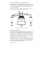
5. OPERATION
5.1 Theory of operation
The ER3000 is a microcontroller-based device that implements a digital control
algorithm to regulate pressure. Supply pressure is allowed into the ER3000 via a
pulse-width modulated solenoid valve at the inlet port, and pressure is reduced
via a similar valve at the exhaust port (normally the exhaust vents to ambient).
In a typical application, the ER3000 loads the dome of a dome loaded regulator
(air to open and a venting type regulator for the purpose of this example) and
senses pressure from a transducer mounted downstream in the process, as shown
in Figure 3. The ER3000 compares the feedback signal to the setpoint every 25
milliseconds. If the feedback is lower than the setpoint, the ER opens its inlet
valve, allowing pressure to flow onto the dome of a pressure reducing regulator.
This opens the main valve of the regulator, increasing pressure downstream. The
ER3000 will continue to increase pressure on the dome of the regulator,
increasing downstream pressure until the feedback signal is equal to the setpoint.
If the setpoint is lowered, so that the feedback is now higher than the setpoint, the
ER3000 will open its exhaust valve, reducing pressure on the dome of the
regulator. This will cause the regulator to self vent, thus lowering downstream
pressure. The ER3000 will continue to reduce pressure on the dome of the
regulator until the feedback signal is equal to the setpoint.
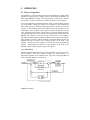
5.1.1 PID Control
PID (Proportional/Integral/Derivative) control algorithm is widely used in the
process industry. The most common example of a PID controller is a
temperature controller for an industrial oven. The basic control algorithm can
best be described through use of Figure 20:
Figure 20: PID Control
28 ER3000 User Manual
In this drawing, the dashed line represents the controller. The setpoint signal,
which is input to the controller, represents the desired level of response (the
desired pressure in this case). The output, which goes to the “system under
control”, is the actuating signal to the process (the amount that each valve is
opened in this case). The feedback signal represents the measured response of
the system (using, for example, a 4-20 mA pressure sensor). Thus, the function
of the controller is to analyze the setpoint and the feedback to produce the output
signal. This is done in the following manner.
Refer to the Figure 20, ignoring for the moment, the lower block containing the
term Kd. We see that the feedback signal is subtracted from the setpoint signal
to form the error signal. The error thus represents the deviation of the actual
system response from the desired response. The output is then produced by
summing two terms. The first term is the product of the error and the constant
Kp (the proportional constant). Thus the larger the error the greater the output is.
The second term is formed by multiplying the integral of the error times the
constant Ki (the integral constant). The effect of the integral is to accumulate the
error over time. The effect of even small errors will eventually cause the output
to increase over time until the system responds and the error is eliminated.
We return now to the effect of the Kd block in the feedback path. This block
multiplies the derivative of the feedback times the constant Kd (the derivative
constant). The derivative is sensitive to rapidly changing signals. Its primary
function in the control algorithm is to suppress oscillations.
“Tuning” a controller is the process of selecting the optimal Kp, Ki, and Kd
constants to yield the “best” response. The “best” response depends on what is
most important for a given application and often becomes a compromise between
response time and stability.
5.2 Control Modes
The ER3000 provides four modes of operation. These modes depend on
whether the feedback signal is derived from the controller’s internal pressure
sensor, a user supplied external sensor (such as a 4-20 mA pressure transducer)
or a combination of the two. The four modes are described in the following
sections.
5.2.1 Internal Feedback Mode
The internal feedback mode uses the ER3000’s temperature compensated
internal sensor to control the output pressure in the 0-100 psig range.
5.2.2 External Feedback Mode
The external feedback mode uses a user supplied external transducer to control
the process pressure. This mode is typically used when using the ER3000 to load
the dome of a mechanical air actuated regulator or control valve. Control of the
5. Operation 29
actual process pressure is obtained by installing a pressure transducer at the
output of the regulator or valve to provide the feedback signal to the ER3000.
External feedback can also be useful when using the ER3000 as a standalone
unit. It may be desirable to measure the pressure downstream from the
controller. For example, if the controller’s output passes through a length of pipe
to a vessel and it is expected that there will be pressure drops in the pipe, then it
may be beneficial to install a pressure transducer at the vessel to provide the
feedback signal.
5.2.3 Cascade Loop Mode
Cascade loop mode implements one PID loop within another PID loop.
The inner loop uses the controller’s internal sensor and the outer loop uses an
external sensor. This mode of operation creates more stability, but slows down
the response of the system.
(Note - For cascade control it is best to set the Integral Minimum = 0 and Integral
Maximum = 32767. This is because it is necessary to maintain a positive
pressure on the dome of the regulator to maintain output pressure from the
system.)
5.2.4 Manual Mode
In manual mode, no control algorithm is implemented. The setpoint is used to
directly control the unit’s pulse width modulators. This mode can be useful for
system testing.
In Windows ER3000 Signal Generator Screen or DOS Tune a setpoint value of:
0% = Fully opens the exhaust solenoid valve
50% = Closes both solenoid valves.
100% = Fully opens the inlet solenoid valve
In Windows ER3000 Read/Write Screen or DOS ERTALK a setpoint value of:
0x0706 = Fully opens the exhaust solenoid valve
0x0800 = Closes both solenoid valves.
0x08fa = Fully opens the inlet solenoid valve
5.3 Setpoint sources
The setpoint for the unit can be derived from one of three sources. It can be:
• Transmitted over the RS485 interface.
• Input from an analog signal (4-20mA, 1-5V, or 0-10V).
• Supplied by an embedded profile.
30 ER3000 User Manual
5.4 Failsafe Limits
Another function of the ER3000 is to detect when programmable limits are
exceeded. Limits can be set on the following variables:
• Analog setpoint.
• Internal feedback.
• External feedback.
• Inner loop error signal.
• Outer loop error signal.
Associated with the limits is a failsafe state that is user defined to set the inlet and
exhaust valves in any desirable combination of open and/or closed states. The
default failsafe state is to close the inlet valve and open the exhaust valve so that
the system will be vented if a limit is exceeded.
Limits can be useful for providing added security in the event of a system failure
such as broken transducer wiring, lack of supply pressure, etc. When limits are
not desired the failsafe modes should be “disabled” (they are disabled when
shipped from the factory).
5.5 LEDs
There are four LEDs (light emitting diodes) on the boards to indicate the status
of the unit. The LEDs indicate the ER3000 is fundamentally operating correctly.
Refer to the Troubleshooting Section for more details on LED indicators.
5.6 RS485 Communication
RS485 communication provides a low cost yet efficient means of communicating
between a computer and a network of ER3000 controllers.
5.6.1 Protocol
In the network the computer serves as a master and all of the controllers as
slaves. Each controller must have a unique node number between 1 and 250.
Controllers have a default node number of 250 when shipped from the factory.
When configuring a network each controller must be individually powered up
and have a unique node number assigned, using Windows ER3000 (CVI) or
DOS tune.exe. The computer initiates all communication and the controllers
respond only to messages that are sent specifically to their node addresses.
The implementation of the Tescom protocol is explained fully in the Software
Programs Section of the manual.
5. Operation 31
6. TUNING PROCEDURE
6.1 Typical Application to Tune
Figure 20: Regulator and ER3000 Internal Operation
32 ER3000 User Manual
Figure22: Typical Tuning Application
6. Tuning Procedure 33
6.2 Tune the Typical Application
This tuning procedure utilizes the Windows Tuning program ER3000 (CVI) and is taken
from the ER3000 (CVI) On Line Help. It applies to the above typical application using
external feedback.
To begin, it should be realized that the tuning of PID controllers is learned with
experience. However, the following basic concepts should allow the inexperienced user
to tune their loops sufficiently for use on a majority of applications.
There are some features of the ER3000 that are unique when compared to other PID
controllers that allow the system to be optimized. In particular, the use of four different
modes of operation, the setting of minimum values for inlet and exhaust valves
(deadband adjust) and the setting of maximum and minimum values for the integral sum
allow for greater flexibility in the ER3000 system.
To begin, three windows should be opened:
• Tuning (Advanced!) --- Select ‘Gains’ in Format Menu
• Signal Generator
• Plot
Each system has unique requirements. Since tuning will always be a compromise
between various tradeoffs, it is necessary to decide what are the most important
parameters for the given application. Typical goals include the following:
• Maximize speed of response.
• Minimize peak overshoot.
• Minimize offset.
• Minimize settling time.
In addition, the region of operation will affect how the unit is tuned. This application will
be operating primarily in the 0 to 2500 psi region. Thus tuning should be performed over
this entire range. However, the final setup should be tested in intermediate pressure
ranges as well, to verify maximum performance throughout the system’s range.
In the Tuning Window, make sure the Control Mode is set to External Feedback and the
Sensor Range Minimum and Maximum are 0 and 2500 respectively. The ER3000 is
shipped with outer loop PID parameters that have been established at the factory to work
well with the regulator in that system, however, in this example we will begin tuning by
setting the parameters as follows:
• Proportional: 200.
• Integral: 0.
• Derivative: 0.
• Integral Minimum: 0.
• Integral Maximum: 0.
34 ER3000 User Manual
(Note - For cascade control it is best to set the Integral Minimum = 0 and Integral
Maximum = 32767. This is because it is necessary to maintain a positive pressure on the
dome of the regulator to maintain output pressure from the system.)
In the Signal Generator, set ‘Setpoint 1’ & ‘Setpoint 2’ to 625 and 1875, which is 25%
and 75%. Make sure that the plot screen is set up to show the entire tuning range. For
example, with the above setpoints, the display should be set up for 0 to 2500.
Since tuning is generally done using step changes, set up 'Wave Type' for option
'TOGGLE'.
Now click on the "Setpoint 1/Setpoint 2" in the Signal Generator to toggle between the
two setpoints.
With the proportional term set to 200, the response will be relatively slow. The first step
in tuning is to see how far the proportional term can be increased. In general, increasing
the proportional term will decrease the response time (i.e. - make the response wave more
square), however a point will be reached at which the effect becomes detrimental. That
is, too much proportional term will result in overshoot and possibly ringing of the
response. Also, it should be noted that the effect of the tuning parameters (PID) tends to
be logarithmic. Thus a possible sequence of values to try for the proportional term might
be 200, 400, 800, 1600, until ringing and/or overshoot occurs and then narrow down to
an optimal value, one which gives just a slight amount of overshoot and ringing.
Next the derivative term should be increased so as to reduce the overshoot and ringing in
the system. However, too much derivative term may result in a noisy output.
Once the optimal proportional and derivative terms are found, the integral term should be
adjusted. The integral term has the effect of eliminating DC offsets, however too much
integral will lead to instability (overshoot and ringing). Again the effect is logarithmic so
values such as 10, 20, 50, 100, 200, 500, 1000 ... can be tried until an optimal value is
obtained.
At this point it should be noted that the ER3000 provides a unique integral limiting
feature ('Minimum Outer Integral' and 'Maximum Outer Integral'). This allows for using
large integral terms without creating excessive overshoot. It should be realized that the
integral sum is what holds the valves open even when there is zero error. For closedended systems the minimum and maximum integrals can be very small. However, for
systems requiring flow it is necessary to keep these values higher. To determine how
small they can be made (remember - smaller is better as long as proper flow is
maintained) the setpoint should be set to the maximum level and the minimum and
maximum reduced until flow is no longer maintained, then slightly increase these values.
Often, for closed ended systems a value of one or two is sufficient.
After performing the steps mentioned above, tuning can often be improved by iterating
between the various parameters. Although performing basic tuning can be simple,
learning to fully optimize the tuning requires experience, so experiment!
6. Tuning Procedure 35
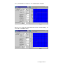
The following is an example sequence of tuning steps. First a very undertuned
response is shown (note size of proportional term).
Next the proportional term is increased, however, overshoot and ringing
results:
36 ER3000 User Manual
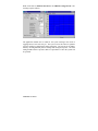
Now, some Derivative is introduced. Note the decrease in overshoot.
However, if we zoom in on the horizontal axis between 1750 and 2000 psi, we
notice that a small offset remains.
6. Tuning Procedure 37
What can be done to eliminate the offset is the addition of integral term. The
resulting response follows:
The application should now be tuned for the system working in the mode of
toggling between 625 and 1875 psi. The system can be fine tuned to optimize
speed or stability by adjusting the tuning parameters. The system can be further
tuned by selecting different pressure settings and testing the response. The final
tuning should be done at pressures that are representative of how the system will
be operated.
38 ER3000 User Manual
7. CALIBRATION
The ER3000 is fully calibrated at the factory. The calibration process involves
temperature compensation and pressure linearization of the internal pressure sensor, and
linearization of both the analog setpoint and external feedback inputs. The additional
inputs and outputs on some models, as referenced in Section 3 (ER3000 Model
Description), are also linearized. The user is able to adjust the calibration as described in
the following sections.
7.1 Zero/span
The calibration of the unit may be changed by adjusting the zero and span settings of the
ER3000. The Zero and Span settings are found on the Miscellaneous Screen of the
Windows ER3000 program.
Normally, the zero and span do not need adjustment since the unit has been factory
calibrated. However, under the following conditions it may be advantageous to make
some adjustment:
•
•
•
•
The application is using a reduced pressure range.
The unit is normally operating under nonstandard temperature conditions
and it is desired to optimize the calibration for this environment.
There has been some long-term drift in the calibration.
An external transducer is being used to provide feedback.
The procedure is as follows:
1. Connect a reference pressure gauge to the output of the ER3000 (or the
output of the booster regulator, if one is being used).
2. Set the setpoint (via the analog setpoint input or the RS485 interface as
appropriate) to a value close to zero (4.16 mA for analog input or 1% for
RS485 interface are recommended).
3. If the reference pressure meter does not indicate 1 psi then increase the
zero value to raise the reading or decrease to lower it, as required.
4. Next, set the setpoint to a value close to 100% (19.2 mA for the analog
setpoint or 95% for RS485 interface are good values).
5. If the reference pressure meter does not indicate 95 psi then increase the
span value to raise the reading or decrease to lower it, as required.
6. Set the setpoint (via the analog setpoint input or the RS485 interface as
appropriate) to a value close to zero (4.16 mA for analog input or 1% for
RS485 interface are recommended).
7. Verify that the pressure meter indicates 1 psi. If not, then repeat above
procedure.
A couple of points should be noted for proper calibration. First, the controller should be
properly tuned before performing calibration, if possible. Second, proper time for the
pressure to settle to a stable value should be allowed for each step. Finally, if the zero is
adjusted too far in the negative direction, then the output will not respond until the zero
is raised to within the control range (i.e. - so that the output is above zero psi).
7. Calibration 39
8. SOFTWARE PROGRAMS
8.1 Windows Tune Program
To run the Windows Tune program, click the ER3000 (CVI) icon.
The Tune program is an all encompassing software package which allows the
user to address any ER3000 Controller on the RS485 network and provides easy
tuning of the ER3000’s. Additionally, the Tune program allows you to monitor
system operation, alter profiles, specify failsafe limits, enable password
protection, read/write internal variables, acquire data, and review previously
acquired data.
The basic screens available are; Signal Generator, Plot, Tuning, Profile, Pulse,
Failsafe, Data Acquisition, Dacq View, Miscellaneous, Read/Write, and
Password.
For more information on the Windows Tune program, see section 6, Tuning
Procedure, which uses the Windows Tune Program to explain how to tune the
ER3000. Information is also available on the Windows Tune program Help
Screens. The help screens are accessed by the Help Menu in the ER3000
Control Window. To access help on a particular Window, right click on the
mouse while that Window is highlighted. To get a printout of the Windows Help
Screens use the file MANUAL.RTF in the MANUAL subdirectory.
8.2 Windows Example Programs
In the WIN16 and WIN32 directories there are four subdirectories of Windows
programs - LabVIEW, Visual Basic, LabWindows (CVI), and “C”. In the
windows directory (i.e. \WINDOWS) there are two files (tescom.dll, tescom.ini)
which are used with any Windows program (see README.DOC file for more
information).
The files in the corresponding subdirectories contain simple programs in the
LabVIEW, Visual Basic, LabWindows (CVI), and “C” languages, illustrating the
use of the tescom.dll (Dynamic Link Library).
There are also two subdirectories, DLL and DLL32. The files in these directories
are used to create the 16 and 32 bit versions of the Tescom DLL.
8.3 Tescom Protocol (Provides Custom Software Support)
The Tescom Protocol used to interface to the ER3000 is non-proprietary. A
description of the protocol is given in PROTOCOL.DOC in the subdirectory
TESCOM2\LIBRARY.
Typically programmers can use the DOS-based library or the Windows-based
DLL provided to aid in communicating to the ER3000. However, not all systems
40 ER3000 User Manual
run on these platforms. We provide all the software used in the development of
the Tescom Protocol library and DLL. This allows the programmer the ability to
alter and recompile the Tescom Protocol in a format suitable for their system.
The Tescom protocol software includes the following six functions:
Startup - This function must be called during program initialization
before any other function to allow PC initialization, including the serial
port. This function does not send any data to the ER3000. This
function needs to be called only once.
WriteNetVar - This function is used to write any of the ER3000
internal variables.
ReadNetVar - This function is used to read any of the ER3000 internal
variables.
WriteProfileSegment - This function is used to write any of the
ER3000 profile segments, 1-32.
ReadProfileSegment - This function is used to read any of the ER3000
profile segments, 1-32.
Shutdown - This function must be called before exiting the program.
This function does not send any data to the ER3000. This function
needs to be called only once.
8.3.1 DOS Library
The Tescom protocol, protocol.lib, allows easy access to the ER3000 from a PC
for DOS-based C-language programs.
One thing to note is that the LIBRARY directory contains two subdirectories one for Microsoft libraries and another for Borland. It is important to use the
PROTOCOL.LIB file from the directory corresponding to the compiler being
used.
Custom DOS applications can be developed easily using the existing software as
a baseline. The ERTALK program demonstrates basic communication with the
ER3000 and is a good starting point for custom software development. The
PROFILE2 program demonstrates the usage of the profiling functions.
8.3.2 Windows DLL
The Tescom protocol, TESCOM.DLL, allows easy access to the ER3000 from a
PC for Windows-based programs.
The protocol is available as a 16-bit and a 32-bit DLL. The proper DLL should
be placed in the Windows directory when generating custom software (this is
automatically done if the Tescom Windows program is installed, ER3000
(CVI)).
Custom Windows applications can be developed easily using the example for the
programming environment being chosen. There are examples for C, Visual
Basic, LabVIEW, and LabWindows/CVI.
9. ER3000 Internal Variables 41
8.3.3 Macintosh Custom Software
The Tescom protocol is provided and written in C. The protocol software can be
easily compiled with custom software for the Macintosh. A demo program is
also provided to ensure proper system operation and provide an example
program using the Tescom protocol software.
8.4 DOS Programs
To run any of the DOS-based programs, type ‘C:\TESCOM2\TESCOM’ at the
DOS prompt and follow the instructions on the display.
Most subdirectories contain a README.DOC file describing the files in the
directory.
8.4.1 Tune
The program TUNE.EXE provides the user with access to many of the
controller’s programmable variables. It also includes a graphics screen for
displaying the setpoint and feedback. In addition, it includes a function generator
for creating waves (square, sine, triangular or sawtooth) that are transmitted as
setpoints to the controller.
This program provides a powerful means of tuning the ER3000. Details on its
use can be found in the file tune.doc.
8.4.2 Ertalk
The program ERTALK.C is a simple program illustrating the use of four of the
library functions. It can be used to read or write any of the controller’s
programmable variables, as outlined in Section 9, “ER3000 Internal Variables”.
8.4.3 Profile
The Profile directory contains a set of programs that will allow users to construct
complete pressure profiles by writing a DOS batch file. Each program will
perform a different profile function (start, ramp, soak or step) and store the
setpoint, feedback and time in a file called data.txt. This file can be imported to a
program such as Excel to plot the profile. The programs and their descriptions
are documented in README.DOC residing in TESCOM2\PROFILE directory.
It should be noted that this method of profiling writes to the ER3000 setpoint
variable, which is different then the embedded profiling capability of the
ER3000. The PROFILE2 program actually downloads pressure profiles into the
ER3000 for embedded pressure profiling.
8.4.4 Profile2
The user may use functions such as: ramp, dwell, step, change variable, loop,
digital in, and digital out to construct the desired profile (refer to Section 3
(ER3000 Model Description) for models with digital in and digital out). The
42 ER3000 User Manual
profile may then be downloaded into the controller. After profile download, it
may be started by software writing variable ID_PROFILE_STATE, a toggle
switch, or by the UI3000/UI4000. See the Readme.doc in the profile2 directory
for a detailed description of the software.
8.4.5 Data_log
This sample data acquisition program provides basic data collection for the user.
The program can be used to read up any of the ER variables and store the
information into an output file. Data_log.cfg is used to configure the data
collection variables including sample time, number of samples, variables to
collect and output file name. See readme.doc in Data_log directory for more
information.
8.4.6 Test_pr
Test_pr.exe resides in the Debug directory. This program can be used as a
simple test for the user to check for node and serial numbers, version of software,
and communication port. This program should be used as part of the
troubleshooting steps described in Section 10, Troubleshooting.
9. ER3000 Internal Variables 43
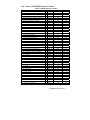
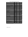
9. ER3000 INTERNAL VARIABLES
The ER3000 has a number of internal variables which can be accessed via the
RS485 interface. The most commonly used variables are listed below. The
variable index number, name, and description are shown. The index number is
the value that is entered in the DOS-based ERTALK program or the Read/Write
Screen of the Windows-based ER3000 (CVI) program to access the specified
variable. A complete list of internal variables is shown in the table at the end of
this section.
9.1 Setpoint and Feedback Variables
37 ID_SETPOINT - This is the controller’s setpoint.
43 ID_SETPOINT_FLAG - This variable determines the source of the
setpoint, variable 37 (ID_SETPOINT).
0 => setpoint from A/D, analog setpoint input
1 => setpoint from RS485 network, typically a PC.
2 => setpoint from internal pressure profile
44 ID_FEEDBACK - This is the controller’s overall feedback signal. For
internal sensor mode it is the same as inner feedback. For external
sensor mode or cascade mode it equals the outer loop feedback.
87 ID_EXT_FEEDBACK_SOURCE - This variable determines the source
of the external feedback.
0 => feedback from the compensated external sensor, see variable 5.
1 => feedback from extra analog input 1, see variable 77.
Note: For both setpoint and feedback a value of 400 counts is 0% and 3700
counts is 100%. To convert between counts and percent, use the following
formulas:
value_percent = (value_counts - 400 ) * 100 / 3300.
value_counts = ( value_percent * 3300 /100) + 400.
9.2 Configuration Variables
9
ID_CONTROL_MODE - This variable establishes the control mode for
the controller. A value of four only occurs when a failsafe condition exists
due to a failsafe limit being exceeded (see variables 54 to 64). A value of
five only occurs if the controller is in ESTOP, emergency stop, mode.
0 => internal feedback mode.
1 => external feedback mode.
2 => cascade mode.
3 => manual mode.
setpoint = 0x08fa => inlet open
setpoint = 0x0800 => solenoids closed
setpoint = 0x0706 => exhaust open
4 => failsafe mode (read only)
5 => emergency stop (read only)
44 ER3000 User Manual
42 ID_NODE - This is the unit’s network node address. Note that if this
variable is changed then all future communication must be addressed to
the new node address.
52 ID_SERIAL_NUMBER - This is the serial number for the unit. It is
programmed at the factory and should not be changed by the user.
53 ID_VERSION_NUMBER - This is the version number of the
embedded software.
9.3 Inner Loop Tuning Variables
35 ID_INNER_PROPORTIONAL_CONSTANT - This is the P-term,
proportional constant, for the inner loop.
28 ID_INNER_INTEGRAL_CONSTANT - This is the I-term, integral
constant, for the inner loop.
3 ID_INNER_D_COEF1 - This is the D-term, derivative constant, for the
inner loop.
50 ID_INNER_INTEGRAL_MINIMUM - This is the minimum value
allowed for the integral sum on the inner loop.
29 ID_INNER_INTEGRAL_MAXIMUM - This is the maximum value
allowed for the integral sum on the inner loop.
30 ID_INNER_INTEGRAL_SUM - This is the value of the integral sum
for the inner loop. It is formed by multiplying the integral constant time
the error and summing the result with the previous value for the integral
sum.
66 ID_INNER_INTEGRAL_DEADBAND - This is the inner loop
minimum error required for the integral sum to be changing in value.
Often it is set to zero and has no effect. However, if it is desirable to
stop integrating once the error is reduced below a certain value, for
instance when using an external dome-loaded regulator which has
hysteresis, then this parameter should be set to the minimum acceptable
error.
6 ID_COMPENSATED_INTERNAL_SENSOR - This is the
compensated internal sensor value, i.e. - after temperature
compensation, zero and span have been applied to the raw signal. A
value of 400 is 0% and 3700 is 100%.
9.4 Outer Loop Tuning Variables
25 ID_OUTER_PROPORTIONAL_CONSTANT - This is the P-term,
proportional constant, for the outer loop.
21 ID_OUTER_INTEGRAL_CONSTANT - This is the I-term, integral
constant, for the outer loop.
16 ID_OUTER_D_COEF1 - This is the D-term, derivative constant, for
the outer loop.
49 ID_OUTER_INTEGRAL_MINIMUM - This is the minimum value
allowed for the integral sum on the outer loop.
9. ER3000 Internal Variables 45
22 ID_OUTER_INTEGRAL_MAXIMUM - This is the maximum value
allowed for the integral sum on the outer loop.
23 ID_OUTER_INTEGRAL_SUM - This is the value of the integral sum for
the outer loop. It is formed by multiplying the integral constant time the
error and summing the result with the previous value for the integral sum.
67 ID_OUTER_INTEGRAL_DEADBAND - This is the outer loop minimum
error required for the integral sum to be changing in value. Often it is set to
zero and has no effect. However, if it is desirable to stop integrating once
the error is reduced below a certain value, for instance when using an
external dome-loaded regulator which has hysteresis, then this parameter
should be set to the minimum acceptable error.
9.5 Analog Input Variables
1
5
77
78
85
86
ID_AD_SETPOINT - This is the value of the analog setpoint. A value
of 400 is 0% and 3700 is 100%. Note that the analog setpoint is not
used unless the controller is programmed to use it (see variable #43).
ID_COMPENSATED_EXTERNAL_SENSOR - This is the
compensated external sensor value, i.e. - after linearization, zero and
span have been applied to the raw signal. A value of 400 is 0% and
3700 is 100%.
ID_COMPENSATED_EXTRA_AD1 - This input is available only on
certain models, refer to section 3. This is the compensated external
analog input value, i.e. - after linearization has been applied to the raw
signal.
ID_COMPENSATED_EXTRA_AD2 - This input is available only on
certain models, refer to section 3. This is the compensated external
analog input value, i.e. - after linearization has been applied to the raw
signal.
ID_AD_EXTRA1_TOGGLE - This variable is used to adjust the level
that the ER3000 interprets the ID_COMPENSATED_EXTRA_AD1
variable as a logical 0 or a logical 1.
ID_AD_EXTRA2_TOGGLE - This variable is used to adjust the level
that the ER3000 interprets the ID_COMPENSATED_EXTRA_AD2
variable as a logical 0 or a logical 1.
9.6 Pressure Profile Control Variables
69 ID_PROFILE_TYPE - This is the type of the profile step currently active.
0 => STOP
1 => RAMP
2 => STEP
3 => DWELL
4 => DIGITAL OUTPUT
5 => DIGITAL INPUT
6 => LOOP
7 => CHANGE VARIABLE
46 ER3000 User Manual
70 ID_PROFILE_STATE - This is the run state of the profile.
0 => STOP
1 => START
2 => RUN
71 ID_PROFILE_STEP - This is the step in the profile which is currently
being run.
119 ID_UI_PROFILE_STARTRUN - This is the restarting mode of the
profile.
0 => Restart profile at the beginning.
1 => Resume profile at current profile step.
9.7 Single “Puff” Solenoid Control Variable
73 ID_PULSE - This variable allows opening the inlet or exhaust for the
specified duration for one pulse period. After one pulse duration, the
variable is returned to a value of 0.
0x08fa => Inlet full open.
0x0800 => Both valves closed.
0x0706 => Exhaust full open.
9.8 Pulse Mode Variables
81 ID_PULSE_PERIOD - This controls the rate of the pulse while pulse
mode is active. The value represents how many passes through the
control algorithm (25ms per pass) before sending a pulse to one of the
solenoids.
82 ID_PULSE_WIDTH - This controls how long the solenoid is held open
while pulse mode is active. Part of this number compensates for
allowed system fluctuations (or noise) so too small a number will not
open the solenoid valve.
83 ID_PULSE_DEADBAND - This is the error from the setpoint allowed
for the pulse function to stop pulsing. This value is in counts read up
from the sensor. One count of error is .03% and typically this number is
in the range of 0-3.
84 ID_PULSE_ENABLE - This turns the pulse function ON(1) or OFF(0).
9.9 Scaling Variables
108
109
110
111
114
115
116
117
ID_UI_UNITS_CHAR1
ID_UI_UNITS_CHAR2
ID_UI_UNITS_CHAR3
ID_UI_UNITS_CHAR4
ID_UI_SCALE_MIN_LO
ID_UI_SCALE_MIN_HI
ID_UI_SCALE_MAX_LO
ID_UI_SCALE_MAX_HI
The "units" variables are used by supplied
software to display the pressure range
units (i.e. psi.).
The scale minimum and scale maximum
variables are used by supplied software to
show minimum and maximum ranges.
9. ER3000 Internal Variables 47
9.10 Analog and Digital Output Variables
88 ID_DIGITAL_OUTPUT1 - This variable can be written directly by a
program or by the embedded profile using the Digital Output command.
This variable is written to Digital Output #1, shown in Table 2,
Auxiliary Cable Assembly.
89 ID_DIGITAL_OUTPUT2 - This variable can be written directly by a
program, by the embedded profile using the Digital Output command,
or by the embedded code. The embedded code updates this output if
variable ID_TTL_FLAG enables this output as a within tolerance
indicator. If enabled, ID_TTL_ERR0 and ID_TTL_ERR4095 variables
are used to set the maximum error allowed, in counts, for a setpoint of 0
and 4095 counts, respectively. The embedded code interpolates
between these points to find the maximum error allowed for all other
setpoint values. Reference ID_SETPOINT and ID_FEEDBACK to
translate between counts and percent. This variable is written to Digital
Output #2, shown in Table 2, Auxiliary Cable Assembly.
90 ID_DIGITAL_OUT1_INIT - Power-up state of ID_DIGITAL_OUT1.
91 ID_DIGITAL_OUT2_INIT - Power-up state of ID_DIGITAL_OUT2.
92 ID_DA_ANALOG_OUT - This is the value written to the D/A
converter to generate the 0-10V or 4-20mA output signal.
93 ID_TTL_ERR0 - Maximum error allowed at 0 counts, see variable 89.
94 ID_TTL_ERR4095 - Maximum error allowed at 4095 counts, see
variable 89.
96 ID_TTL_FLAG - This variable enables(1) or disables(0) the usage of
ID_DIGITAL_OUTPUT2 as a within tolerance indicator.
9.11 PWM Control Variables
12 ID_PWM_SHUTOFF_FLAG – This flag is only active if
ID_RTTASK_DELAY (variable #13) is not a 0 or 1 and designates
what the ER3000 will send to the PWM every 25ms while it is delaying.
0 => Write the previously computed value to the PWM
1 => Write a 0 to the PWM.
13 ID_RTTASK_DELAY – This variable is set to 0 typically, allowing the
control algorithm to generate a new value for the PWM every 25ms.
Certain systems need a slower acting control system which is allowed by
with this variable, for example writing a 4 to this variable will allow the
control algorithm to compute a new PWM value every 100ms.
19 ID_INNER_SENSOR_MIN – This variable operation is typically
disabled by writing a 0 to it. If not disabled, it allows for a minimum
internal pressure. If the internal pressure is below the specified value
the exhaust valve will not be opened to decrease the pressure.
20 ID_INNER_SENSOR_MAX – This variable operation is typically
disabled by writing a 4095 to it. If not disabled, it allows for a maximum
internal pressure. If the internal pressure is above the specified value,
the inlet valve will not be opened to increase the pressure.
48 ER3000 User Manual
34 ID_OUTPUT - This is the value of the output from the controller. It is
this value which controls the ER3000’s valves. A positive number will
open the inlet valve and a negative number will open the outlet valve.
46 ID_SOLENOID - This variable determines which valve is open when
the output is positive or negative. In normal mode, (0 => Normal)
positive outputs open the inlet solenoid and negative outputs open the
exhaust solenoid. In reversed mode, (1 => Reversed) positive outputs
open the exhaust solenoid and negative outputs open the inlet solenoid.
This is useful in reverse acting systems (i.e. - in systems where
increasing the pressure causes the process variable to decrease).
47 ID_MIN_INLET - This is the minimum value for the inlet pulse width
modulator. The pulse width modulator’s value ranges from 0 to 250.
This variable (along with variable #48) sets the deadband for the
system. This variable is solenoid dependant and typically a value close
to 10. Larger values can give tighter regulation, but at a cost of more
gas being exhausted.
48 ID_MIN_EXHAUST - This is the minimum value for the exhaust pulse
width modulator. The pulse width modulator’s value ranges from 0 to
250. This variable (along with variable #47) sets the deadband for the
system. This variable is solenoid dependant and typically a value close
to 10. Larger values can give tighter regulation, but at a cost of more
gas being exhausted.
65 ID_PWM_VALUE - This is the value which is controlling the PulseWidth Modulators for the solenoids. Positive values represent the inlet
solenoid opening and negative values are for the exhaust solenoid. A
value of +/- 250 represents a 100% duty cycle (full on).
9.12 Gain/Offset Variables
39 ID_GAIN - This is the gain value. This value in conjunction with the
offset (variable #40) is used to form the feedback signal (see variable
#44):
feedback = gain * compensated_reading + offset.
0x0200 =>
1/8 ( .2% adjustability)
0x1000 =>
1 (.025% adjustability)
0x8000 =>
8 (.003% adjustability)
40 ID_OSET - This is the offset value. This value in conjunction with the
gain (variable #39) is used to form the feedback signal (see variable
#44):
feedback = gain * compensated_reading + offset.
0x0000 =>
-1/2 FS
0x0fff =>
+1/2 FS
9.13 Failsafe Variables
64 ID_PWM_FAILSAFE - This variable establishes the failsafe state of
the unit which is established if any of the programmed limits is
9. ER3000 Internal Variables 49
exceeded. Normally, the unit will be set up to open the exhaust and
close the inlet valve if a limit is exceeded. Also note, when shipped from
the factory the limits are set to their limits (i.e. - disabled). The unit will
automatically remove itself from failsafe if the failsafe limit is no longer
exceeded.
0 => IN_CLOSED_EX_CLOSED
1 => IN_OPEN_EX_CLOSED
2 => IN_CLOSED_EX_OPEN
3 => IN_OPEN_EX_OPEN
Failsafe Limits for Specified Signals
These variables are the minimum and maximum values allowed for a given
signal that is permissible before tripping a limit and causing the unit to go into
failsafe.
Minimum/Maximum
Limited Signal
54 ID_MIN_AD_SETPOINT
55 ID_MAX_AD_SETPOINT
56
ID_MIN_COMPENSATED_INTERNAL_SENSOR
57
ID_MAX_COMPENSATED_INTERNAL_SENSOR
58
ID_MIN_COMPENSATED_EXTERNAL_SENSOR
59
ID_MAX_COMPENSATED_EXTERNAL_SENSOR
60 ID_MIN_INNER_ACTUAL_ERROR
61 ID_MAX_INNER_ACTUAL_ERROR
62 ID_MIN_OUTER_ACTUAL_ERROR
63 ID_MAX_OUTER_ACTUAL_ERROR
50 ER3000 User Manual
1 ID_AD_SETPOINT
6
ID_COMPENSATED_INTERNAL_SENS
OR
7
ID_COMPENSATED_EXTERNAL_SENS
OR
0 ID_INNER_ACTUAL_ERROR
14 ID_OUTER_ACTUAL_ERROR
9.14 Table of all ER3000 Internal Variables
Table 3: ER3000 Internal Variables
Variable Name and Number
Type
0 - ID_INNER_ACTUAL_ERROR
* Signed
1 - ID_AD_SETPOINT
* Unsigned
3 - ID_INNER_D_COEF1
Signed
4 - ID_INNER_D_COEF2
- Unused
5 - ID_COMPENSATED_EXTERNAL_SENSOR
* Unsigned
6 - ID_COMPENSATED_INTERNAL_SENSOR
* Unsigned
7 - ID_RAW_EXTERNAL_SENSOR
* Unsigned
8 - ID_RAW_INTERNAL_SENSOR
* Unsigned
9 - ID_CONTROL_MODE
Signed
10 - ID_INNER_DERIVATIVE
* Signed
11 - ID_INNER_EFFECTIVE_ERROR
* Signed
12 – ID_PWM_SHUTOFF_FLAG
Unsigned
13 - ID_RTTASK_DELAY
Unsigned
14 - ID_OUTER_ACTUAL_ERROR
* Signed
16 - ID_OUTER_D_COEF1
Signed
17 - ID_OUTER_D_COEF2
- Unused
18 - ID_OUTER_EFFECTIVE_ERROR
* Signed
19 - ID_INNER_SENSOR_MIN
Unsigned
20 - ID_INNER_SENSOR_MAX
Unsigned
21 - ID_OUTER_INTEGRAL_CONSTANT
Signed
22 - ID_OUTER_INTEGRAL_MAXIMUM
Signed
23 - ID_OUTER_INTEGRAL_SUM
Signed
25 - ID_OUTER_PROPORTIONAL_CONSTANT
Signed
26 - ID_FACTORY_MIN_INLET
Unsigned
27 - ID_FACTORY_MIN_EXHAUST
Unsigned
28 - ID_INNER_INTEGRAL_CONSTANT
Signed
29 - ID_INNER_INTEGRAL_MAXIMUM
Signed
30 - ID_INNER_INTEGRAL_SUM
Signed
34 - ID_OUTPUT
* Signed
35 - ID_INNER_PROPORTIONAL_CONSTANT
Signed
37 - ID_SETPOINT
Unsigned
38 - ID_RAW_TEMP_SENSOR
* Unsigned
39 - ID_GAIN
Unsigned
40 - ID_OSET
Unsigned
41 - ID_ARDG
* Unsigned
42 - ID_NODE
Unsigned
43 - ID_SETPOINT_FLAG
Signed
44 - ID_FEEDBACK
* Unsigned
46 - ID_SOLENOID_DIRECTION
Signed
47 - ID_MIN_INLET
Unsigned
48 - ID_MIN_EXHAUST
Unsigned
49 - ID_OUTER_INTEGRAL_MINIMUM
Signed
50 - ID_INNER_INTEGRAL_MINIMUM
Signed
51 - ID_RAW_AD_SETPOINT
* Unsigned
52 - ID_SERIAL_NUMBER
Unsigned
53 - ID_VERSION_NUMBER
Unsigned
54 - ID_MIN_AD_SETPOINT
Unsigned
* - Denotes Read Only, all other variables are Read/Write.
Range:Decimal
-4095 : 4095
0 : 4095
-32,768 : 32,767
--0 : 4095
0 : 4095
0 : 4095
0 : 4095
0:3
-32,768 : 32,767
-32,768 : 32,767
0:1
0 : 65535
-4095 : 4095
-32,768 : 32,767
---32,768 : 32,767
0 : 4095
0 : 4095
-32,768 : 32,767
-32,768 : 32,767
-32,768 : 32,767
-32,768 : 32,767
0 : 250
0 : 250
-32,768 : 32,767
-32,768 : 32,767
-32,768 : 32,767
-32,768 : 32,767
-32,768 : 32,767
0 : 4095
0 : 4095
0 : 65,535
0 : 65,535
0 : 65,535
1 : 250
0:2
0 : 4095
0:1
0 : 250
0 : 250
-32,768 : 32,767
-32,768 : 32,767
0 : 4095
0 : 65,535
0 : 65,535
0 : 4095
Range:Hex
-0fff : 0fff
0 : 0fff
-8000 : 7fff
--0 : 0fff
0 : 0fff
0 : 0fff
0 : 0fff
0:3
-8000 : 7fff
-8000 : 7fff
0:1
0 : ffff
-0fff : 0fff
-8000 : 7fff
---8000 : 7fff
0 : 0fff
0 : 0fff
-8000 : 7fff
-8000 : 7fff
-8000 : 7fff
-8000 : 7fff
0 : fa
0 : fa
-8000 : 7fff
-8000 : 7fff
-8000 : 7fff
-8000 : 7fff
-8000 : 7fff
0 : 0fff
0 : 0fff
0 : ffff
0 : ffff
0 : ffff
1 : fa
0:2
0 : 0fff
0:1
0 : fa
0 : fa
-8000 : 7fff
-8000 : 7fff
0 : 0fff
0 : ffff
0 : ffff
0 : 0fff
9. ER3000 Internal Variables 51
Table 3 (continued): ER3000 Internal Variables
Variable Name and Number
55 - ID_MAX_AD_SETPOINT
56 - ID_MIN_COMPENSATED_INTERNAL_SENSOR
57 -ID_MAX_COMPENSATED_INTERNAL_SENSOR
58 - ID_MIN_COMPENSATED_EXTERNAL_SENSOR
59-ID_MAX_COMPENSATED_EXTERNAL_SENSOR
60 - ID_MIN_INNER_ACTUAL_ERROR
61 - ID_MAX_INNER_ACTUAL_ERROR
62 - ID_MIN_OUTER_ACTUAL_ERROR
63 - ID_MAX_OUTER_ACTUAL_ERROR
64 - ID_PWM_FAILSAFE
65 - ID_PWM_VALUE
66 - ID_INNER_INTEGRAL_DEADBAND
67 - ID_OUTER_INTEGRAL_DEADBAND
68 - ID_FEEDBACK_FILTER
69 - ID_PROFILE_TYPE
70 - ID_PROFILE_STATE
71 - ID_PROFILE_STEP
72 - ID_ESTOP_FLAG
73 - ID_PULSE
74 - ID_EXTRA_AD1
75 - ID_EXTRA_AD2
76 - ID_DAC
77 - ID_COMPENSATED_EXTRA_AD1
78 - ID_COMPENSATED_EXTRA_AD2
79 - ID_RANGE_MIN_INLET
80 - ID_RANGE_MIN_EXHAUST
81 - ID_PULSE_PERIOD
82 - ID_PULSE_WIDTH
83 - ID_PULSE_DEADBAND
84 - ID_PULSE_ENABLE
85 - ID_AD_EXTRA1_TOGGLE
86 - ID_AD_EXTRA2_TOGGLE
87 - ID_EXT_FEEDBACK_SOURCE
88 - ID_DIGITAL_OUTPUT1
89 - ID_DIGITAL_OUTPUT2
90 - ID_DIGITAL_OUT1_INIT
91 - ID_DIGITAL_OUT2_INIT
92 - ID_DA_ANALOG_OUT
93 - ID_TTL_ERR0
94 - ID_TTL_ERR4095
95 - ID_DA_ANALOG_WRITE_FLAG
96 - ID_TTL_FLAG
98 – ID_SENSOR_FLAG
*
*
*
*
*
*
*
Type
Unsigned
Unsigned
Unsigned
Unsigned
Unsigned
Signed
Signed
Signed
Signed
Signed
Signed
Unsigned
Unsigned
Unsigned
Unsigned
Unsigned
Unsigned
Unsigned
Unsigned
Unsigned
Unsigned
Unsigned
Unsigned
Unsigned
Unsigned
Unsigned
Unsigned
Unsigned
Unsigned
Unsigned
Unsigned
Unsigned
Unsigned
Unsigned
Unsigned
Unsigned
Unsigned
Unsigned
Unsigned
Unsigned
Unsigned
Unsigned
Unsigned
* - Denotes Read Only, all other variables are Read/Write.
52 ER3000 User Manual
Range:Decimal
0 : 4095
0 : 4095
0 : 4095
0 : 4095
0 : 4095
-32,768 : 32,767
-32,768 : 32,767
-32,768 : 32,767
-32,768 : 32,767
0:3
-250 : 250
0 : 4095
0 : 4095
0:1
0:7
0:2
0 : 31
0:1
1798 : 2298
0 : 4095
0 : 4095
0 : 65,535
0 : 4095
0 : 4095
0 : 20
0 : 20
0 : 200
0 : 250
0 : 330
0:1
0 : 4095
0 : 4095
0:1
0:1
0:1
0:1
0:1
0 : 255
0 : 4095
0 : 4095
0:1
0:1
0:1
Range:Hex
0 : 0fff
0 : 0fff
0 : 0fff
0 : 0fff
0 : 0fff
-8000 : 7fff
-8000 : 7fff
-8000 : 7fff
-8000 : 7fff
0:3
-fa : fa
0 : 0fff
0 : 0fff
0:1
0:7
0:2
0 : 1f
0:1
0706 : 08fa
0 : 0fff
0 : 0fff
0 : ffff
0 : 0fff
0 : 0fff
0 : 14
0 : 14
0 : c8
0 : fa
0 : 14a
0:1
0 : 0fff
0 : 0fff
0:1
0:1
0:1
0:1
0:1
0 : 0ff
0 : 0fff
0 : 0fff
0:1
0:1
0:1
Most of the following variables are used exclusively by the UI3000/UI4000.
The exceptions are the sensor range variables, 108-111 and 114-117, and the
profile restart, variable 119. The profile restart variable is the only one that is
used by the embedded software.
Table 3 (continued): ER3000 Internal Variables
Variable Name and Number
100 - ID_UI_INIT
101 - ID_UI_LOCK_FLAG
102 - ID_UI_PASSWORD_ENABLE
103 - ID_UI_USER_PASSWORD
104 - ID_UI_GRAPH_MIN
105 - ID_UI_GRAPH_MAX
106 - ID_UI_GRAPH_TIME
107 - ID_UI_GRAPH_CONTINUOUS
108 - ID_UI_UNITS_CHAR1
109 - ID_UI_ UNITS_CHAR2
110 - ID_UI_ UNITS_CHAR3
111 - ID_UI_ UNITS_CHAR4
112 - ID_UI_REMOTE_SP1
113 - ID_UI_REMOTE_SP2
114 - ID_UI_SCALE_MIN_LO
115 - ID_UI_ SCALE_MIN_HI
116 - ID_UI_ SCALE_MAX_LO
117 - ID_UI_ SCALE_MAX_HI
118 - ID_UI_SP1OR2_FLAG
119 - ID_UI_PROFILE_STARTRUN
120 - ID_UI_DECIMAL_POSITION
121 - ID_UI_BACKLIGHT
122 - ID_UI_CONTRAST
Type
Range:Decimal
Range:Hex
Unsigned
Unsigned
Unsigned
Unsigned
0 : 255
0 : 255
0 : 255
0 : 255
0 : ff
0 : ff
0 : ff
0 : ff
float %
float %
float %
float %
0 : 65,535
0 : 65,535
0 : 65,535
0 : 65,535
0 : ffff
0 : ffff
0 : ffff
0 : ffff
Unsigned
0:1
0:1
#
#
#
#
#
#
#
#
#
#
#
#
#
#
# - Denotes usage by the UI3000/UI4000 only, all other variables are Read/Write.
% - Denotes 32-bit floating point numbers for the scale_min and scale_max variables.
9. ER3000 Internal Variables 53
10. TROUBLESHOOTING
10.1 LED Indicators
1 2 3 4 5 6 7 8 9 101112 1 2 3 4 5 6 7 8
J3
J4
J5
1
2 3
4
LED3
LED2
LED1
Figure 21: LED Locations
Table 4: LED Indicators
Terminal (Top) Board
LED1, red = On continuously, if power is supplied to the ER3000.
LED2, green = On if ER3000 is sending data out, via RS485.
LED3, amber = On if ER3000 is receiving data in, via RS485.
Micro (Bottom) Board
LED1, red = blinks “heartbeat” if system is functioning properly.
Additionally, the Micro (Bottom) Board LED, LED1, blinks once per second,
staying on more than off, when the system is functioning properly. If this LED is
on or off continuously then the electronics are not functioning. This LED will
also blink at a different rate, twice a second, if the zero or span buttons have been
pressed too long, causing their corresponding limits to be exceeded. If a failsafe
limit has been exceeded, the LED will also blink once per second, but will be off
more than on.
54 ER3000 User Manual
10.2 Third Party RS232/RS485 Converters
The RS232/RS485 converters range in modes of operation. The provided
Tescom software needs the RS232/RS485 converter to be configured in the
following mode.
Table 5: Third Party RS232/RS485 Converter Mode
Echo off.
Transmitted data, SD, is used for flow control.
No handshake control (RTS/CTS, DSR/DTR).
Additionally, for 4-wire RS422 converters (half duplex).
Connect: +TD to +RD.
Connect: -TD to -RD.
10.3 ER3000 Power-up Test, using LED Indicators
Power up the ER3000 without any Tescom provided software packages running.
Check the LED indicators on the ER3000.
Table 6: LED’s, Power Up
Terminal (Top) Board
LED1, red = ON
LED2, green = OFF
LED3, amber = OFF
Micro (Bottom) Board
LED1, red = BLINKING
If the LED indicators are not as specified in Table 6, refer to Figure 2 to ensure
proper wiring. Check power wiring if the red LED’s are off. Check the RS485
wiring if the amber LED is on. Check to ensure no jumper is on J3 of the micro
(bottom) board if the green LED is on. If not using a Tescom RS485/RS232
converter, refer to Table 5 for proper mode of operation.
If unable to resolve the problem, contact your local distributor. A list of Tescom
distributors may be found on our website, www.tescom.com, or by contacting the
factory.
10.4 ER3000 Data Communications Test, using LED Indicators
For Windows
These procedures assume
- You have followed the instructions in Sections 4.4.3 thru 4.4.6 to run the
Windows Tune program.
- You are using a Tescom converter or some other converter that has TxD
& RxD indicator lights. If you are not using a Tescom converter, refer to
Table 5 for proper setup
- The test above, “Power-up Test of the ER3000, using LED Indicators”,
works.
10. Troubleshooting 55
•
If the “Comm Error” window pops up, click on “Search Network”. As the
program scrolls through the nodes, check the TxD light on the converter.
o If it is not blinking, you are not connected to that comm port.
When the search is completed, change the comm port and repeat
until you find the correct comm port.
o If it is blinking,
Check the LED indicators on the ER3000.
Table 7: LED’s, Data Transfer
Terminal (Top) Board
LED1, red = ON
LED2, green = BLINKING
LED3, amber = BLINKING
Micro (Bottom) Board
LED1, red = BLINKING
If the LED indicators are not as specified in Table 7, refer to Figure 2 to
ensure proper wiring. If the amber LED, LED3, is OFF, suspect the
wrong COM port setting. If the amber LED, LED3, is BLINKING and
the green LED, LED2, is OFF, suspect the wrong node address.
•
•
•
If the error message “Tescom Startup failed. DLL may be in use by
another application”, click “OK” and use the ‘Channel Selection’ box to
change the comm port. Repeat the above step.
If you try all 4 comm ports without success then try the following:
1. Go to Device Manager: Depending on your operating system,
it may be in MyComputer\Control
Panel\System\Hardware\Device Manager
2. Click on “Ports” – this will list all the comm ports on your
computer.
3. If your communications port is higher than 4, you will need to
go to the Tescom.ini file and change it there. This file is
installed automatically during the Windows Tune installation.
It is found in the windows directory on your computer hard
drive.
4. After changing the comm port in the file, save the file and run
Windows Tune.
If after trying the comm port found in the Device driver, you are still
unable to establish communications, run Hyperterminal (typically found
in Programs\Accessories\Communications).
1. A “Connection Description” box will open for a new
connection. Enter any name, such as “abc” and click “OK”.
2. A “Connect To” box titled “abc” will open. Use the dropdown menu at “Connect Using:” to connect to the comm port
in question (i.e. COM2). Click “OK”.
56 ER3000 User Manual
♦
If the port is in use by another application then the error
message “Unable to open COM2” will appear. That port
will have to be freed up before it can be used by the
ER3000 software.
♦
If a connection box does appear, check the LED indicators
on the ER3000
For DOS
This procedure assumes:
- The Tescom “ER3000 User Software” CD, DOS install has been installed
- The communications hardware is configured, as shown in Figure 2.
- The test above, “Power-up Test of the ER3000, using LED Indicators”,
works.
• Run ERTALK by Typing: “\tescom2\tescom 1” at a DOS prompt (i.e. C:\>).
• Type in the node address (250 if unknown).
• Select “1” to “Read ER-3000”.
• Type “44” for parameter index, any parameter works.
• If “Node x : Variable Number 44 = ...” scrolls on the screen, communication
to the ER3000 is working. Otherwise, “Error” is scrolling, LET IT
SCROLL.
If unable to resolve the problem, contact your local distributor. A list of Tescom
distributors may be found on our website, www.tescom.com, or by contacting the
factory.
10.5 Pressure Control Problems
If there is a problem with controlling the pressure:
• Check for pneumatic connections: the inlet pressure (max:120 psig)
must go into the inlet port (marked “IN” on the unit). The gauge port
must be plugged if gauge not installed.
• Check the control mode and setpoint source using the provided software.
• Check the values of the PID parameters using the provided software.
• Check the unit’s calibration: see the Calibration Section for details.
10.6 Acceptable Resistance Values
The resistance values must be measured with all external wiring disconnected,
including the power. Ensure converter screw terminals are tight.
10.6.1 ER3000 RS485 Interface
• +RS485 to GND = 10KΩ to 50KΩ
• -RS485 to GND = 10KΩ to 50KΩ
10.6.2 Converter RS485 Interface
• +RS485 to GND = 3K to 5KΩ
• -RS485 to GND = 900Ω to 1.2KΩ
10. Troubleshooting 57
10.7 Leak Test
The ER3000 can be leak tested using the DOS Tune program or the Windows
ER3000(CVI) program. Prior to running the leak test, ensure the following items
are done.
• ER3000 wired up and communicating to the computer.
• 100psi is applied to the inlet of the ER3000.
• The outlet port of the ER3000 is plugged.
10.7.1 Windows ER3000 Program
Setup Screens as Shown in Table
Signal Gen.
Plot
Tuning
Control Mode: Manual
Sensor Range: 0/100
(Min/Max)
Signal Type:
Setpoint 1:
Setpoint 2:
Toggle
0
50
Axis, Vertical: -5/105
(Min/Max)
Axis, Time:
5
Misc.
Span: 100
Zero: 0
(Need not be
ex act )
Procedure:
• Open “PLOT” and “SIGNAL GENERATOR” Screens
• Click on Setpoint 1, wait until feedback reaches 0
• Click on Setpoint 2
• Watch the feedback signal for 25 seconds, it should remain constant
If feedback increases, the inlet solenoid is leaking
• Change Setpoint 1 to 100
• Click on Setpoint 1
• Wait for feedback to stabilize, which takes approximately 5 seconds
• Click on Setpoint 5
• Watch feedback signal for 25 seconds, it should remain constant
If feedback decreases, the unit is leaking
• If leaking, plug exhaust port with finger and release
If pressure buildup at exhaust, then exhaust solenoid is leaking
10.7.2 DOS Tune Program
Main Screen Settings
i = 50
j=0
l = toggle
m = -5
Setpoint #1
Setpoint #2
Wave Type
Display, Lower
n = 105
o=5
w=0
x = 100
Display, Upper
Timebase
Sensor Range, Low
Sensor Range, High
Setup Screen Settings
a = 100 (approx.)
b = 0 (approx.)
c = Manual
d = Digital
Procedure:
• From the TUNE Main Screen, select ‘b’ to run plot.
• Press “spacebar” to toggle Setpoint to 0.
• Wait until Feedback reaches 0.
• Press “spacebar” to toggle Setpoint to 50.
• Watch the Feedback (FB) signal for 25 seconds.
If feedback increases, the inlet solenoid is leaking
• Change ‘j’ (Setpoint #2) to 100.
• Press “spacebar” to toggle Setpoint to 100.
58 ER3000 User Manual
Span
Zero
Mode
Setpoint
Source
• Wait for Feedback to stabilize, which takes approximately 5 seconds.
• Press “spacebar” to toggle Setpoint to 50.
• Watch Feedback signal for 25 seconds.
If feedback decreases, the unit is leaking
• If leaking, plug exhaust port with finger and release
If pressure buildup at exhaust, then exhaust solenoid is leaking
10. Troubleshooting 59
11. ER3000 Accessories
Part #
Description
82699
12 pin MTA (connector only)
85138-X
12 wire cable assembly (5, 10, 20, 50 and 100 foot options)
85121
12 wire cable assembly – 24”
85139-X
8 wire cable assemble (5, 10, and 20 foot options)
85122
8 wire cable assembly – 24”
85137
Fitting Kit (includes ¼”x 1/8” NPT, ¼”x ¼” NPT, and a
male tube connector)
80279
Filter
85145
Filter Kit
82575-25
250 mA/24VDC Power Supply
82575-50
500 mA/24VDC Power Supply
85061
RS232 to RS485 converter
82948
USB to RS485 converter
82919
Potentiometer with digital display
60 ER3000 User Manual
12. MECHANICAL DIMENSIONS OF ER3000
NOTE: DIMENSIONS ARE IN INCHES AND ARE FOR REFERENCE
ONLY
12. Mechanical Dimensions of ER3000 61
NOTE: DIMENSIONS ARE IN INCHES AND ARE FOR REFERENCE
ONLY
62 ER3000 User Manual
CE Declaration of Conformity
Manufacturer’s Name:
Tescom Corporation
Manufacturer’s Address:
12616 Industrial Boulevard
Elk River, Minnesota 55330-2491
United States of America
European Contact:
Marc Lembcke
TESCOM EUROPE GMBH & CO. KG
An der Trave 23-25
23923 Selmsdorf
Germany
+49/38823/31-0
declares that the product:
Product Name:
Electronic Pressure Controller
Model Number:
ER3000
to which this declaration relates, is in conformity with the relevant EU Directives
listed below:
EU EMC Directive 89/336/EEC
using the relevant section of the following EU standards and other normative
documents:
EN55011
Limits and measurements of RFI for Industrial,
Scientific and Medical (ISM) Equipment
EN50082-2
Generic Immunity for Heavy Industrial
Environment
Approval: Jim Tomczak
Title: Vice President &
Chief Financial Officer
INDUSTRIAL CONTROLS
12616 Industrial Boulevard
Elk River, Minnesota 55330-2491
TEL 1-800-447-1250 (763) 241-3238
FAX (763) 241-3224
E-mail: [email protected]
www.tescom.com
Form No. 1893 Rev. 1/07 Printed 1/07 2M