1
Cadmould® 3D-F
simcon kunststofftechnische Software GmbH
2012 / Version 6.0
-1-
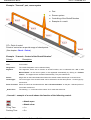
Cadmould® 3D-F
Table of contents:
2012 / Version 6.0
Page:
1. Introduction.............................................................................................14
1.1 Why to simulate an injection molding process?....................................................14
1.2 What can Cadmould® 3D-F do?...........................................................................14
1.3 How exact calculates Cadmould® 3D-F?.............................................................15
2. Installation ..............................................................................................16
2.1 Software requirements..........................................................................................16
2.2 Hardware requirements........................................................................................16
2.3 Before the installation...........................................................................................16
2.4 Installation.............................................................................................................16
3. Starting Cadmould® 3D-F......................................................................17
3.1 Command Line Options........................................................................................17
3.1.1 Program language...........................................................................................17
3.1.2 Full Screen.......................................................................................................17
3.2 3D Display with stereo projection..........................................................................18
4. Carrying out a simulation......................................................................19
4.1 Load a geometry ..................................................................................................19
4.1.1 Load at the beginning......................................................................................19
4.1.2 Replace............................................................................................................20
4.1.3 Merge...............................................................................................................20
4.2 The runner system................................................................................................21
4.2.1 Runner segment..............................................................................................21
4.2.2 Select Function ...............................................................................................22
4.2.3 Zoom................................................................................................................22
4.2.4 Calculation.......................................................................................................22
4.2.5 Hot/Cold Runner..............................................................................................22
4.2.6 Update.............................................................................................................23
4.2.7 Delete...............................................................................................................23
4.2.8 Further cross-sections of a runner segment....................................................23
4.2.8.1 Needle valve nozzle/ annular shape...........................................................23
4.2.8.2 Rounded trapezoid......................................................................................24
4.2.8.3 Square.........................................................................................................24
4.2.8.4 Trapezoid....................................................................................................24
simcon kunststofftechnische Software GmbH
-2-
2012 / Version 6.0
4.2.8.5 Rounded square..........................................................................................25
Cadmould® 3D-F
4.2.8.6 Virtual Runner Segments............................................................................25
4.2.9 Example of a runner system............................................................................25
4.2.9.1 First runner segment...................................................................................26
4.2.9.2 Second runner segment..............................................................................27
4.2.9.3 Third runner segment ................................................................................28
4.2.10 Construction assistance.................................................................................28
4.3 Gate......................................................................................................................29
4.3.1 Define a gate location......................................................................................29
4.3.1.1 Enter the Gates...........................................................................................29
4.3.1.2 Edit..............................................................................................................30
4.3.1.3 Delete..........................................................................................................30
4.3.1.4 Optimizing the gate locations......................................................................31
4.3.1.5 Display Flow Length / Thickness.................................................................31
4.4 Sensors.................................................................................................................31
4.5 Cascade Injection Molding....................................................................................32
4.6 Select a material...................................................................................................35
4.7 Define the process conditions...............................................................................36
4.7.1 Vary the process conditions.............................................................................36
4.8 Flow Rate / Pressure Input Profile........................................................................37
4.8.1 Split Bar...........................................................................................................38
4.8.2 Edit Bar............................................................................................................38
4.8.2.1 Flow-Rate Variation.....................................................................................39
4.8.3 Remove Bar.....................................................................................................39
4.8.4 Clamping Force Limitation...............................................................................40
4.8.5 Injection Pressure Limitation............................................................................40
4.8.6 Switch dep. on.................................................................................................40
4.8.7 No inflow..........................................................................................................40
4.8.8 Pressure...........................................................................................................40
4.9 Heterogeneous Hot-Runner Temperatures..........................................................41
4.10 Wall Temperature Distribution............................................................................41
4.10.1 Uniform Wall Temperature.............................................................................41
4.10.2 Assigned Wall Temperatures.........................................................................41
simcon kunststofftechnische Software GmbH
-3-
2012 / Version 6.0
4.10.3 Wall temperature analysis..............................................................................42
Cadmould® 3D-F
4.11 Packing ..............................................................................................................43
4.11.1 Packing Variation...........................................................................................44
4.12 S+W (Shrinkage and Warpage) .........................................................................45
4.12.1 Fix Surfaces...................................................................................................46
4.13 Inserts (Simulation with Inserts or 2K-Simulations)............................................47
4.13.1 Boundary and Initial Conditions.....................................................................48
4.14 Heat Transfer Coefficient....................................................................................49
4.15 Injection Compression........................................................................................51
4.16 Describe and store the simulation.......................................................................51
4.17 Start the simulation.............................................................................................52
4.18 Cancel the simulation..........................................................................................52
4.19 Stored Results ...................................................................................................52
5. Toolbar "Edit".........................................................................................53
5.1 Copy.....................................................................................................................53
5.1.1 Copy the part and the runner system...............................................................53
5.1.2 Connecting all runner systems.........................................................................54
5.2 Mirror....................................................................................................................55
5.3 Rotate...................................................................................................................56
5.4 Delete...................................................................................................................57
5.5 Cut........................................................................................................................57
5.6 Undo – Function ..................................................................................................58
6. Design of a symmetrical cavity.............................................................59
6.1 Reconstruct w/o symmetries.................................................................................61
7. Toolbar "Wall Temperature" .................................................................63
7.1 Mold......................................................................................................................63
7.2 Heating/Cooling-channel segments......................................................................64
7.2.1 Bore.................................................................................................................64
7.2.2 Bend.................................................................................................................64
7.2.3 Baffle................................................................................................................65
7.2.4 Bubbler.............................................................................................................65
7.2.5 Hose.................................................................................................................65
7.2.6 Type Conversion..............................................................................................66
simcon kunststofftechnische Software GmbH
-4-
2012 / Version 6.0
7.2.7 Design Aid for Heating/Cooling Systems.........................................................66
Cadmould® 3D-F
7.2.7.1 Drilling.........................................................................................................66
7.2.7.2 Moving heating/cooling segments...............................................................67
7.2.8 Repair of heating/cooling segments.................................................................67
7.3 Heating/Cooling Circuits.......................................................................................67
7.4 Save Heating/Cooling system...............................................................................68
7.5 Import a Heating/Cooling System.........................................................................68
7.6 Options – Wall Temperature Analysis...................................................................69
7.6.1 Material ...........................................................................................................70
7.6.2 Cycle................................................................................................................70
7.6.3 Heat Flow.........................................................................................................71
7.6.4 Element Length................................................................................................71
7.6.5 Simulation........................................................................................................71
7.6.6 Snapshot..........................................................................................................72
7.6.7 Inserts..............................................................................................................72
7.7 Wall Temperature Analysis...................................................................................74
7.8 Cooling system manufactured of STL...................................................................75
7.8.1 Close-to-contour cooling channel.....................................................................75
7.8.2 Drilled cooling channel.....................................................................................77
7.9 Example of a heating/cooling system...................................................................80
8. Stack and compute projects ................................................................95
9. Result selection......................................................................................98
9.1 Result groups........................................................................................................99
9.2 Result details......................................................................................................100
9.2.1 Local Results.................................................................................................102
9.2.2 Result Display................................................................................................103
9.2.2.1 Air Traps....................................................................................................103
9.2.2.2 Weld Lines................................................................................................103
9.2.2.3 Sink Marks................................................................................................103
9.2.2.4 Displayed Limits........................................................................................103
9.2.2.5 Clamping Force.........................................................................................104
9.2.2.6 Cavity........................................................................................................105
9.2.2.7 Flow Direction...........................................................................................105
simcon kunststofftechnische Software GmbH
-5-
2012 / Version 6.0
9.2.2.8 Orientation.................................................................................................105
Cadmould® 3D-F
9.2.2.9 Deformation (Shrinkage and Warpage).....................................................106
9.2.2.10 3-Click Transformation............................................................................107
9.2.2.11 Shrinkage Allowance...............................................................................107
9.3 Interior results.....................................................................................................108
9.3.1 Activating the results......................................................................................109
9.3.2 Display of interior results................................................................................110
9.4 Animation of cross-sectional profiles..................................................................112
9.5 3D flow front........................................................................................................113
9.5.1 Activate the display of the 3D flowfront..........................................................113
9.6 Evaluation of multiple results..............................................................................114
9.7 Loading New Results..........................................................................................114
10. Description of results........................................................................115
10.1 Result Summary...............................................................................................115
10.2 Cavity................................................................................................................115
10.3 Flow Front.........................................................................................................115
10.4 Snapshot Filling................................................................................................116
10.5 Filling Orientation Degree.................................................................................116
10.6 Force and Moment............................................................................................117
10.7 Diagrams..........................................................................................................117
10.7.1 Diagram Functions.......................................................................................118
10.7.2 Functions in the Context Menu....................................................................118
10.7.2.1 Limits.......................................................................................................118
10.7.2.2 Division....................................................................................................118
10.7.2.3 Display of the Curve................................................................................118
10.7.2.4 Delete Curve...........................................................................................118
10.7.2.5 Curve to the bottom.................................................................................118
10.7.2.6 Scale Like Active Curve..........................................................................119
10.7.2.7 Smooth Curve.........................................................................................119
10.7.2.8 Maximize Curve......................................................................................119
10.7.2.9 Rename Curve........................................................................................119
10.7.2.10 Curve => Table.....................................................................................119
10.7.2.11 Load Curves..........................................................................................119
simcon kunststofftechnische Software GmbH
-6-
2012 / Version 6.0
10.7.2.11.1 From File..........................................................................................119
Cadmould® 3D-F
10.7.2.11.2 From Clipboard.................................................................................119
10.7.2.12 Variation................................................................................................120
10.7.2.13 Store Image File....................................................................................120
10.8 Residual Stress.................................................................................................120
10.9 Part Quality.......................................................................................................120
10.10 Snapshot Packing...........................................................................................121
10.11 Shrinkage & Warpage - Cooling.....................................................................121
10.12 Shrinkage & Warpage (Ejection).....................................................................121
10.13 Shrinkage & Warpage (Final)..........................................................................122
10.14 Interior.............................................................................................................122
10.15 Residual Stress Interior...................................................................................122
10.16 Wall Temperature Analysis.............................................................................122
10.17 Heating/Cooling System.................................................................................123
10.18 Sensor............................................................................................................124
11. Variation Results................................................................................125
11.1 Summary..........................................................................................................125
11.2 Bar Charts.........................................................................................................125
11.3 Compare Curves...............................................................................................125
12. Examples of the results ....................................................................126
12.1 Example: Force and Moment............................................................................129
13. Animations..........................................................................................131
13.1 Online Animations.............................................................................................131
13.2 Single-Step Frames..........................................................................................131
13.3 Store Animations..............................................................................................132
14. Report Filling Analysis .....................................................................133
14.1 Define a Report Standard ................................................................................135
14.2 Import Results...................................................................................................136
14.3 Edit a Report.....................................................................................................136
15. Cadmould® 3D-F Viewer...................................................................136
16. Menu Bar.............................................................................................137
16.1 File....................................................................................................................137
simcon kunststofftechnische Software GmbH
-7-
2012 / Version 6.0
16.1.1 Open............................................................................................................137
Cadmould® 3D-F
16.1.1.1 Project.....................................................................................................137
16.1.1.2 Runner System.......................................................................................137
16.1.1.3 H/C System.............................................................................................137
16.1.1.4 Cadmould® 3D-F Any Result (CAR).......................................................138
16.1.2 Save.............................................................................................................138
16.1.2.1 Project.....................................................................................................138
16.1.2.2 H/C System.............................................................................................138
16.1.2.3 Runner System.......................................................................................138
16.1.3 Import ..........................................................................................................139
16.1.3.1 Mesh Files...............................................................................................139
16.1.3.2 Material Data...........................................................................................140
16.1.3.3 Wall Temperatures..................................................................................140
16.1.4 Export ..........................................................................................................141
16.1.4.1 Cadmould® 3D-F FE...............................................................................141
16.1.4.2 NASTRAN...............................................................................................141
16.1.4.3 STL..........................................................................................................141
16.1.4.4 Compensation of Shrinkage and Warpage Results................................142
16.1.4.5 Material Data...........................................................................................144
16.1.4.6 Wall Temperatures..................................................................................144
16.1.5 Convert........................................................................................................144
16.1.5.1 CAR -> Txt..............................................................................................144
16.1.5.2 RM1 -> CFE............................................................................................145
16.1.5.3 BMP/PNG -> AVI.....................................................................................145
16.1.6 Explore Project Directory.............................................................................145
16.1.7 Auto Store....................................................................................................145
16.1.8 Save Animation............................................................................................145
16.1.9 Save Image..................................................................................................145
16.1.10 Save Window.............................................................................................146
16.1.11 Print............................................................................................................146
16.1.12 Print Option................................................................................................146
16.1.13 Print Setup.................................................................................................146
16.1.14 Recent File List..........................................................................................146
simcon kunststofftechnische Software GmbH
-8-
2012 / Version 6.0
16.1.15 Exit ............................................................................................................146
Cadmould® 3D-F
16.2 Edit....................................................................................................................147
16.2.1 Default Settings............................................................................................147
16.2.2 Geometry.....................................................................................................147
16.2.2.1 General...................................................................................................147
16.2.2.1.1 Scale..................................................................................................147
16.2.2.1.2 Transform...........................................................................................148
16.2.2.2 Groups....................................................................................................151
16.2.2.3 Heating/Cooling Channel........................................................................152
16.2.2.4 Measuring Devices..................................................................................152
16.2.2.5 Mould → Mounting Position....................................................................156
16.2.2.6 Parts........................................................................................................157
16.2.2.6.1 DeskArtes...........................................................................................157
16.2.2.6.2 Element Orientation............................................................................158
16.2.2.6.3 Erase Embossed Labels....................................................................158
16.2.2.6.4 Mesh Prepare.....................................................................................159
16.2.2.6.5 Mesh Refine.......................................................................................159
16.2.2.6.6 Thickness...........................................................................................160
16.2.2.7 Runner....................................................................................................162
16.2.2.8 Symmetry................................................................................................162
16.2.2.8.1 Build Symmetrical Cavity....................................................................162
16.2.2.8.2 Reconstruct w/o Symmetries..............................................................162
16.2.3 Language.....................................................................................................163
16.2.4 Material........................................................................................................163
16.2.4.1 Class.......................................................................................................163
16.2.5 Text Labels..................................................................................................163
16.2.5.1 New.........................................................................................................163
16.2.5.2 Visible......................................................................................................164
16.2.6 Wall Temperature........................................................................................164
16.3 View..................................................................................................................165
16.3.1 Toolbars.......................................................................................................165
16.3.1.1 Visibility...................................................................................................165
16.3.1.1.1 Recently Used Functions...................................................................165
simcon kunststofftechnische Software GmbH
-9-
2012 / Version 6.0
16.3.1.2 Configuration of Toolbars........................................................................165
Cadmould® 3D-F
16.3.2 Status Bar....................................................................................................166
16.3.3 Colours.........................................................................................................167
16.3.3.1 Air Trap...................................................................................................167
16.3.3.2 Results....................................................................................................168
16.3.3.2.1 Default (color scale: 0 - 255).............................................................168
16.3.3.2.2 simcon (color scale: 0 - 14)...............................................................168
16.3.3.2.3 Gray (black-and-white).......................................................................168
16.3.3.2.4 Traffic Light.........................................................................................168
16.3.3.3 Background.............................................................................................168
16.3.3.4 Parts........................................................................................................168
16.3.4 Cutaway.......................................................................................................169
16.3.5 Font..............................................................................................................169
16.3.6 Save.............................................................................................................170
16.3.6.1 Store Views.............................................................................................170
16.3.6.2 Select A View..........................................................................................170
16.3.6.3 Delete A View..........................................................................................170
16.3.7 Split Screen..................................................................................................170
16.3.8 Standard Views............................................................................................170
16.3.9 Zoom............................................................................................................170
16.3.9.1 Full size...................................................................................................170
16.3.9.2 Rectangle................................................................................................170
16.3.10 Look vertically at... ....................................................................................171
16.3.11 Mesh Statistic.............................................................................................171
16.3.12 Projected Area...........................................................................................172
16.3.13 Projection...................................................................................................172
16.3.14 Options.......................................................................................................172
16.3.14.1 All..........................................................................................................172
16.3.14.2 Visibility.................................................................................................172
16.3.14.3 Miscellaneous.......................................................................................172
16.3.14.3.1 Lighting.............................................................................................172
16.3.14.3.2 Gloss [%]..........................................................................................173
16.3.14.3.3 Continuous Tone (continuous color).................................................173
simcon kunststofftechnische Software GmbH
- 10 -
2012 / Version 6.0
16.3.14.3.4 Lines / Color.....................................................................................173
Cadmould® 3D-F
16.3.14.3.5 Symm. Objects.................................................................................173
16.3.14.3.6 Opacity [%].......................................................................................173
16.3.14.3.7 Hidden Groups Translucent..............................................................174
16.3.14.3.8 Display Part (geometry on / off)........................................................174
16.3.14.3.9 Transparency unfilled domains [%]..................................................174
16.3.14.4 Animation..............................................................................................174
16.3.14.4.1 Animation Frames............................................................................174
16.3.14.4.2 Animation Duration...........................................................................174
16.3.14.4.3 Video Codec.....................................................................................174
16.3.14.5 Image width in image files.....................................................................174
16.3.14.6 Results..................................................................................................175
16.3.14.6.1 Longest Flow Path............................................................................175
16.3.14.6.2 Cross-Sectional Profiles...................................................................175
16.3.14.6.3 Local Value vs. Time........................................................................175
16.3.14.6.4 Force and Moment...........................................................................175
16.3.14.6.5 Minimum / Maximum........................................................................176
16.3.14.6.6 Arrow Length (permille)....................................................................176
16.3.14.6.7 Deformation Amplification.................................................................176
16.3.14.6.8 Zero-Deformation Center..................................................................176
16.3.14.6.9 Results on Inserts.............................................................................176
16.3.14.6.10 Short-Shot Markers........................................................................177
16.3.14.6.11 Contrast Amplification of the color scale........................................177
16.3.14.7 Mesh.....................................................................................................177
16.3.14.7.1 Element Edges.................................................................................177
16.3.14.8 Perspective/Stereo................................................................................177
16.3.14.9 Mouse...................................................................................................178
16.4 Simulation.........................................................................................................179
16.4.1 Gates ..........................................................................................................179
16.4.2 Sensors........................................................................................................179
16.4.3 Shutoff Nozzles............................................................................................180
16.4.4 Material........................................................................................................180
16.4.4.1 Enter the material ...................................................................................180
simcon kunststofftechnische Software GmbH
- 11 -
2012 / Version 6.0
16.4.4.2 Toolbox: Cadmould® 3D-F material data base......................................181
Cadmould® 3D-F
16.4.4.3 Add your own material data into material data base...............................181
16.4.4.4 Diagrams in the material data base ........................................................182
16.4.4.5 Data exchange........................................................................................182
16.4.4.5.1 Export.................................................................................................182
16.4.4.5.2 Import.................................................................................................183
16.4.5 Process........................................................................................................183
16.4.6 Gate Variation..............................................................................................183
The function “Gate Variation” makes it possible for you, to compare different gating
positions by variant calculations with each other....................................................183
The window "Gate Variation" appears on the screen.............................................184
16.4.7 Thickness/Diameter Variation......................................................................184
16.4.7.1 Object groups..........................................................................................185
16.4.8 Force and Moment.......................................................................................186
16.4.9 Description...................................................................................................187
16.4.10 Simulation..................................................................................................187
16.4.11 Cadmould® 3D-F Task Schedule.............................................................187
16.4.12 Options ......................................................................................................188
16.4.12.1 Model....................................................................................................188
16.4.12.1.1 Element Edge Length.......................................................................188
16.4.12.1.2 Wall Thickness.................................................................................188
16.4.12.1.3 Automatic Mesh Refinement............................................................188
16.4.12.1.4 Symmetry Check..............................................................................188
16.4.12.1.5 Old Thickness Method......................................................................189
16.4.12.1.6 Keep mesh structure........................................................................189
16.4.12.1.7 Remesh............................................................................................189
16.4.12.1.8 Virtual Runners.................................................................................189
16.4.12.2 Clamping Force.....................................................................................190
16.4.12.3 Snapshot Filling.....................................................................................190
16.4.12.4 Snapshot Packing.................................................................................190
16.4.12.5 Optional Results....................................................................................191
16.4.12.6 Shape Factors.......................................................................................191
16.4.12.7 Shrinkage and Warpage (Residual Stress)...........................................193
simcon kunststofftechnische Software GmbH
- 12 -
2012 / Version 6.0
16.4.12.8 Gravity...................................................................................................194
Cadmould® 3D-F
16.4.12.9 Runner Balancing..................................................................................195
16.4.12.10 Temperatures after Ejection................................................................195
16.4.12.11 Inserts.................................................................................................196
16.5 Results..............................................................................................................197
16.5.1 Animation.....................................................................................................197
16.5.2 Check ..........................................................................................................197
16.5.3 Diagram.......................................................................................................197
16.5.4 Report..........................................................................................................197
16.5.5 Selection......................................................................................................197
16.5.6 Variation.......................................................................................................197
16.6 Help..................................................................................................................198
16.6.1 Manual.........................................................................................................198
16.6.2 TeamViewer.................................................................................................198
16.6.3 Cadmould Wiki.............................................................................................198
16.6.4 About Cadmould® 3D-F...............................................................................198
17. Controls...............................................................................................199
17.1 Button Bar.........................................................................................................199
17.2 Mouse Control + Keyboard...............................................................................201
17.2.1 Combination of keys....................................................................................201
17.2.2 Light.............................................................................................................201
17.2.3 Rotation........................................................................................................201
17.2.4 Zoom............................................................................................................202
17.2.5 Pan...............................................................................................................202
18. Copyrights...........................................................................................203
19. Non-liability.........................................................................................203
20. Appendix ............................................................................................204
21. Reference registers............................................................................210
simcon kunststofftechnische Software GmbH
- 13 -
Cadmould® 3D-F
2012 / Version 6.0
1. Introduction
1.1 Why to simulate an injection molding process?
The complexity of today's plastic parts as well as the costs, quality and competition pressure
makes it necessary to recognize potential errors early, already in the development phase of
parts and molds in order to solve the problems in the design phase. The most flexible, reliable
and economical tool for this is the software Cadmould® 3D-F. It is available today with sufficient efficiency and is meant to support the experienced injection molding specialist in recognizing and solving problems with the manufacturing process, because simulation is better than
trials.
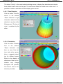
Very often the location of air traps and weld lines is an important topic. With the injection moulding simulation you can optimally define the points of injection or change the wall thickness
before the actual injection moulding process in order to shift the location of the weld lines into
uncritical areas. You can avoid air traps. The simulation enables you to optimize the process
parameters. It quickly supplies you with results for cost reduction of your products.
1.2 What can Cadmould® 3D-F do?
Cadmould® 3D-F stands for patented technology (EP 1 385 5103).
The special 3D-framework (3D-F) crosslinking method has the advantage, that the 3D-F mesh,
which is needed for simulation, is generated automatically. Please see the appendix for more
information.
Cadmould® 3D-F is a “Computer Aided Engineering (CAE)” software. It is possible to simu-
late the filling phase of the injection molding process depending on the assigned thermoplastic
material and process parameters.
Cadmould® 3D-F Warp Expert users can calculate shrinkage and warpage of the
part. As most important results the filling pattern, the pressure loss and the remaining cooling
time and warpage are output. Thus different conditions and suppositions can be compared very
easily. In addition to the pure filling of the part (re: Cadmould® 3D-F Rapid) complicate
runner systems (hot and cold) and heating/cooling systems can be balanced.
Cadmould® 3D-F simulates also the cascade injection moulding process. The clamping
force limitation and injection pressure capacity of the injection moulding machine may be considered in the calculation of the filling simulation. Based on certain boundary conditions Cadmould® 3D-F can compute the flow rate profile automatically.
In order to run a simulation, it is necessary to describe the part geometry. Normally the part
geometry is available from the CAD system. The CAD format, which is utilized by Cad-
simcon kunststofftechnische Software GmbH
- 14 -
Cadmould® 3D-F
2012 / Version 6.0
mould® 3D-F, is the so called STL-format (stereo lithography - format). This data format can
also originate from a 3rd party conversion program.
Cadmould® 3D-F is also able to simulate multi-cavity and family molds. The connecting
runner systems can be defined inside the system or imported from CAD system by IGES files.
Calculations are carried out applying a non-isothermal and, if applicable also compressible, multilayer approach.
The material data base distributed with the program can be edited and extended.
This manual describes the whole function range of Cadmould® 3D-F.
Depending on the license you have purchased, different functions are available to you.
On this CD-ROM you find also the stand alone program Cadmould® 3D-F Viewer:
Cadmould® 3D-F Viewer is a program to present all possible results of a Cadmould® 3D-F calculation.
This software has to be installed separately. To do this, please start the setup in the subfolder
“CMViewer” on this CD-ROM.
Please contact your distributor in case of questions about the license.
On the Cadmould® 3D-F product information CD you find the Cadmould® 3D-F Viewlets. Cadmould® 3D-F Viewlets are animated product descriptions, which comes near to a
first step tutorial.
The content can also be used for product demonstrations.
1.3 How exact calculates Cadmould® 3D-F?
By own benchmarking from simcon in national and international public founded research projects, as well as by Cadmould® 3D-F users is guaranteed, that Cadmould® 3D-F
Rapid can provide very exact results.
The results of the simulation with reinforced and non-reinforced materials are in the range of the
process variation and measuring tolerance.
simcon kunststofftechnische Software GmbH
- 15 -
Cadmould® 3D-F
2012 / Version 6.0
2. Installation
2.1 Software requirements
Windows® XP/Vista (32bit, 64bit), Windows ® 2000, MS-EXCEL® (from Office 97), Browser MS-Internetexplorer or Firefox, Acrobat Reader (V9.0 contained on CD)
2.2 Hardware requirements
fast CPU, option: multi core CPU, min. 1 GB RAM, min 50 GB free hard disk space, graphic
adapter with OpenGL support, USB 2.0 port, 3 button mouse, option: SpaceNavigator ®, CDROM or DVD-ROM
2.3 Before the installation
Cadmould® 3D-F Rapid can be installed by an administrator only.
Cadmould® 3D-F Rapid is delivered on CD-ROM. The license file will be send by email.
To install the USB Dongle:
Please, attach the provided dongle to a USB port on your computer. Regard, that the red LED
on the dongle lights. In some cases it is possible, that the dongle is not recognized, then please
try another USB port.
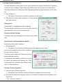
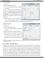
2.4 Installation
To install please insert the CD ROM into your CD-ROM. The installation procedure should start
automatically after a short time. If the installation procedure does not begin, start the routine by
hand:
1) Open the Windows-Explorer.
2) Change to the CD-ROM and open the root directory.
3) Start the installation program »Starter(.exe)«
installation directory
The directory, where the software is to be installed. The standard is »C:\Program files\Cadmould\Rapid«. For reasons of uniformity the program system should be installed into the
given directory.
4) Indicate the location of the license file.
This is the directory where you saved the license file from the mail.
simcon kunststofftechnische Software GmbH
- 16 -
2012 / Version 6.0
Cadmould® 3D-F
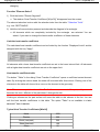
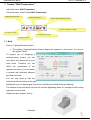
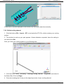
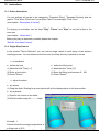
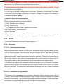
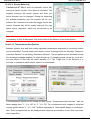
3. Starting Cadmould® 3D-F
You can start Cadmould® 3D-F by double-clicking on the icon on your desktop, if this was
created during the installation procedure, or you start it by: "Start Programs Cadmould
Fill Cadmould® 3D-F ".
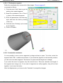
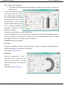
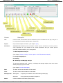
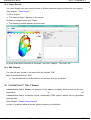
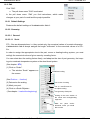
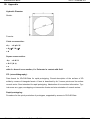
Thus you receive the following "start" window:
Toolbar - Standard
Status Bar
Toolbar – Edit
Toolbar - Walltemperatures
Working Area
Please look up specific menus and buttons in the topics "Menu Bar" resp. "Button Bar".
3.1 Command Line Options
The command line options allow to start Cadmould® 3D-F and Cadmould® 3D-F
Tasklist with user-specific settings.
These options are suffixed to the <cadmould.exe> resp. <tasklist.exe> on the register attributes
of the desktop icon. The following options are available among others:
3.1.1 Program language
With the command "-lng language" you can define the language which is used at the start of
Cadmould® 3D-F.
The different languages are abbreviated by the first three characters of the language name.
e.g.: eng; ger; fre; ita; spa; por;
3.1.2 Full Screen
If you add the command "-fsc", Cadmould® 3D-F is started in full screen mode.
simcon kunststofftechnische Software GmbH
- 17 -
Cadmould® 3D-F
2012 / Version 6.0
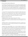
3.2 3D Display with stereo projection
You now have the possibility to display the part stereoscopically.
To use this function you need the following hardware which supports this:
•
a graphics card with quad buffering, e.g. nVIDIA Quadro
•
shutter glasses
•
a display or projector with a frequency of at least 120 Hz
If you want to use this function, you have to start Cadmould 3D-F with the command line option
“-prm 2”. You cannot switch between orthogonal and stereoscopic view while the program is
running.
Therefore it is advisable to create two desktop icons, one with the command line option “-prm 2”
to start the program in stereoscopic mode and one without these option to start it normally.
Please see also chapter: 11.3.13.6 Perspective/Stereo
simcon kunststofftechnische Software GmbH
- 18 -
2012 / Version 6.0
Cadmould® 3D-F
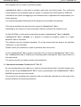
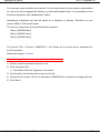
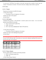
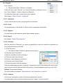
4. Carrying out a simulation
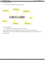
Perform a simulation by filling in the menus appearing after clicking the buttons from left to the
right.
Simulation
Description
Gate Editor
Material Selection
Cadmould Task Schedule
Import STL File
Runner Segments
Process Parameters
Check-Point
Editor
Shutoff Nozzles
Simulation Start
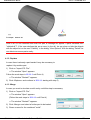
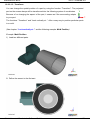
4.1 Load a geometry
You can load a geometry, replace the old one and load a new. Or you can add another (different) geometry to the one loaded. That means, you can merge two different geometries.
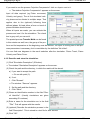
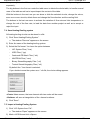
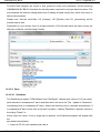
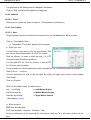
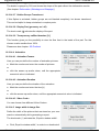
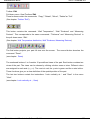
4.1.1 Load at the beginning
(See chapter: Appendix → STL file)
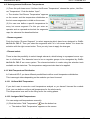
(1) Click on the icon "Import STL File".
The window "Open" appears on screen.
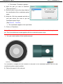
(2) Browse to the directory with the STL-file (stereo lithography file) describing your part geo metry. (Example geometries are shipped with the software. You find them in the subdirectory
geom in the installation path.)
(3) Click on the file: Example: becher.stl
(4) Click on "Open".
(5) Wait for the geometry to load and appear on the screen.
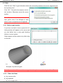
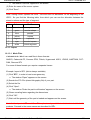
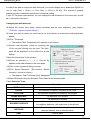
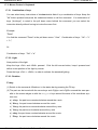
The window "Scale the part to millimeters" appears.
(6) Compare
the
size
of
the
bounding box of your part with
the units given on the left side
in this window. Click the unit
which gives the right size of
your part and then "OK", or
scale the part to your needs in
the scale window "?" and then click “OK”.
(See chapter: Scale)
simcon kunststofftechnische Software GmbH
- 19 -
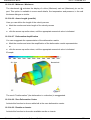
Cadmould® 3D-F
2012 / Version 6.0
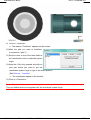
Example: becher.stl
Note: If an STL-file contains more than one part, a message will appear "n parts extracted from
"rubbish.stl"!". If the user declines this as an error (in the stl), he can show or hide the objects
with the object list on the card "Visibility" in the dialog "View Options" With the dialog "Delete" he
can delete erroneous parts easily.
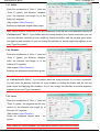
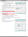
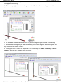
4.1.2 Replace
In case there is already a part loaded it may be necessary to
replace it by another part.
1) Click on "Import STL File".
The window "Open" appears.
Follow the work steps in 15.1.1.1 until Point 4)
The window "Restart?" appears.
2) Click <Replace> and continue in 15.1.1.1 starting with step 5)
4.1.3 Merge
In case you want to simulate a multi-cavity mold this step is necessary.
1) Click on "Import STL File".
The window "Open" appears.
(Follow the work steps in 15.1.1.1 until Point 4)
The window "Restart?" appears.
2) Click <Merge> and select a further part to be loaded.
3) Chose a name for the combined "mold".
simcon kunststofftechnische Software GmbH
- 20 -
Cadmould® 3D-F
2012 / Version 6.0
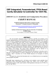
Example: becher+loc3
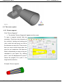
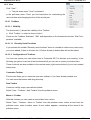
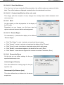
4.2 The runner system
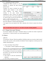
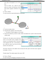
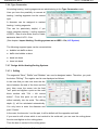
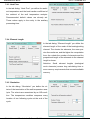
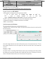
4.2.1 Runner segment
Click "Runner Segment".
The window "Runner Segments" appears on the screen.
To input a segment several data are
necessary. These form the information of
the vertices of starting and ending point
(color coded red and green) as well as
the diameters at each end. There is more
than one way to define these data. Use
what fits your needs best. Edit fields are
filled in automatically as soon as they are
redundant to your inputs. E.g. defining
point 1 and the displacement to point 2
makes the program fill in point 2, the
length and the direction.
Example: Runner segment
simcon kunststofftechnische Software GmbH
- 21 -
Cadmould® 3D-F
2012 / Version 6.0
4.2.2 Select Function
All coordinates can be defined by a mouse-click.
Position the cursor in the field you want to get the coordinates for. Keep the <Ctrl> key pressed
and click on the part or onto that end of an existing segment (red or green) where you want to
position the runner segment. The coordinates on the part or of the center line’s end of the runner segment are transferred to the input field.
Any displacement or direction can be grabbed in the same manner, tangents and the bending
direction for linking bends and hoses (heating/cooling segments) with already existing
heating/cooling segments can be transferred to the input field, e.g. the vector normal to a surface or a segment’s start to end displacement. Picking the colored end of a segment gives the
direction of the front face of the segment. The cursor focus must be in one of the X/Y/Z fields
prior to selection.
Diameter and length information can be picked accordingly.
Parts and runner segments can be selected with “<Ctrl>+left mouse button” directly at the
screen.
Note: You can also define a direction, by putting the letter of a standard direction, like X/Y/Z into
the first field of direction. Put in the letter with opposite sign, to turn the direction 180°.
4.2.3 Zoom
Activate this button to show the segment full screen. This makes it easier to find the
segment in a complex runner system.
4.2.4 Calculation
For a conical segment by default the angle is calculated based on given length and both ending
diameters. You may also give this angle and one diameter and have the missing diameter
added.
Click the symbol of the value you want to have calculated.
4.2.5 Hot/Cold Runner
Before creating a segment you can define it as a “Hot Runner” by setting the tag “ Hot Runner”.
A “Hot Runner” is shown in red and yellow stripes. A “Cold Runner” is shown in blue and yellow
stripes.
For every hot runner segment can later in the process parameter window a temperature be
assigend.
Please see also: Chapter Heterogeneous Hot Runner Temperature.
simcon kunststofftechnische Software GmbH
- 22 -
Cadmould® 3D-F
2012 / Version 6.0
4.2.6 Update
1) Click the arrow “New” or “Existing” down or up to open a segment you want to update.
2) Change the parameter(s).
3) Click < Update >.
If you don’t click <Update> the changes will be not effective.
4.2.7 Delete
1) Click the arrow “New” or “Existing” down or up to open a segment you want to delete.
The selected part or segment is highlighted red.
2) Click on <Delete>.
4.2.8 Further cross-sections of a runner segment
All runner segments (square, rounded square, trapezoid, rounded trapezoid, annular shape) you
create appear as cylindrical or bevel runner segments on the screen, as the program uses the
hydraulic diameter in simulation. Furthermore so far it is not possible to define or display an orientation of non-symmetric shapes.
(See the technical and/or theory manual)
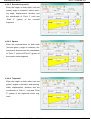
4.2.8.1 Needle valve nozzle/ annular shape
Enter the inside and outside diameter on
both sides (red and green), displacement,
direction + length and the coordinates of
“Point 1” (red) and “Point 2” (green) of the
runner segment.
simcon kunststofftechnische Software GmbH
- 23 -
2012 / Version 6.0
Cadmould® 3D-F
4.2.8.2 Rounded trapezoid
Enter the height on both sides (red and
green), angle of retraction, radius, opening angle, displacement, direction and
the coordinates of “Point 1” (red) and
“Point
2”
(green)
of
the
rounded
trapezoid.
4.2.8.3 Square
Enter the cross-sections on both ends
(red and green), angle of retraction, displacement, direction and the coordinates
of “Point 1” (red) and “Point 2” (green) of
the square runner segment.
4.2.8.4 Trapezoid
Enter the height on both sides (red and
green), angles of retraction and opening,
width, displacement, direction and the
coordinates of “Point 1” (red) and “Point
2” (green) of the trapezoid runner segment.
simcon kunststofftechnische Software GmbH
- 24 -
2012 / Version 6.0
Cadmould® 3D-F
4.2.8.5 Rounded square
Enter the height on both ends (red and
green), width, angle of retraction, displacement, direction and the coordinates
of “Point 1” (red) and “Point 2” (green) of
the runner segment.
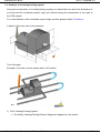
4.2.8.6 Virtual Runner Segments
Virtual Runner segments make it possible to connect an existing runner system with a part, without a direct contact
at the section. The melt will be transported through the segment without delay
and pressure loss.
These virtual segments are applicably
e.g. at a test dimensioning, if an approximate shape of the runner is known, but
the
exact
balancing
connection
is
searched. Then different versions can be analysed without much changing time and effort.
Finally, the best version should be checked again with a runner, build with regular runner seg ments.
Note: A virtual runner segment is displayed as a thin, yellow-white striped segment. The displayed diameter serves only for a better recognisability.
4.2.9 Example of a runner system
It is advised to build the runner system off the part to guarantee a correct connection to the part.
Furthermore think in segments, i.e. from one change of direction or diameter to the following.
simcon kunststofftechnische Software GmbH
- 25 -
2012 / Version 6.0
Cadmould® 3D-F
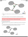
4.2.9.1 First runner segment
1) Click "Runner segment".
The window "Runner Segments" appears.
1) Set the cursor in one of the three fields of <Point 1> (red).
2) Keep the <Ctrl> key pressed and click on your part where you want to link the runner seg ment with the part. Point 1 will receive the coordinates of the selected surface point. To get
the coordinates of the second point, you can either:
enter them directly,
enter the direction (e.g. by
mouse click) and the length,
enter the displacement.
3) Enter the parameters of the
runner segment.
4) Before
you
click
<Create>
leave the last field by pressing
the <Tab> key. (If the option
<Create> still doesn’t appear,
click the <Tab> key more
times. Make sure to define the
runner segment completely.)
5) Click <Create> to get the segment on the screen.
As you can define both diameters of a segment the sketch in the window “Runner Segments” is
not representative by its dimensions. The diameter at <Point 1> (red) may be smaller than that
at <Point 2> (green) opposing the sketch.
The left diameter (red) has been projected onto the cups bottom.
simcon kunststofftechnische Software GmbH
- 26 -
2012 / Version 6.0
Cadmould® 3D-F
4.2.9.2 Second runner segment
A new runner segment can only be defined if the segment number input field at the center top
reads “new”.
Already existing segments (the input field reads “Existing” and a segment is highlighted red) can
be updated or deleted.
Define the coordinates by mouse-click, or you proceed as follows:
1) Click the arrow “New” down to get the existing, last created segment.
2) Swap the coordinate of the <Point 2>
(green) of the previous segment.
3) Enter the parameters of the second
segment and leave the field by clicking <Tab> key. If you didn’t define a
new segment, i.e. didn’t enter displacement
or
direction,
you
will
receive an error message, as you are
up to creating a identical segment.
4) Click the arrow “Existing” up to create
a new segment.
5) Click on <Create>.
simcon kunststofftechnische Software GmbH
- 27 -
Cadmould® 3D-F
2012 / Version 6.0
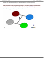
4.2.9.3 Third runner segment
Define the coordinates by a mouse-click (See chapter: “Runner segment”),
or proceed as follows:
1) Click the arrow “New” down to get the
existing, last created segment.
2) Swap the coordinate of the < Point 2
> (green) of the second segment.
3) Enter the parameters of the third segment and leave the field by clicking
<Tab> key.
4) Click the arrow “Existing” up to create
a new segment.
5) Click on <Create>.
4.2.10 Construction assistance
It´s now possible to move runner segments by drag and drop in space. To do this, select the
segment with CTRL + middle mouse button. If you select the segment on the boundary surface,
you will move the whole segment. The direction in space and the length won´t change.
If you select the end of a segment, only this end will move. Take care, direction and length of
the segment can change now. If two ends of segments are visibly together, they will be fixed
together, if you loose the button.
After the displacement, you have to click "Actualize" to accept the changes.
simcon kunststofftechnische Software GmbH
- 28 -
Cadmould® 3D-F
2012 / Version 6.0
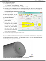
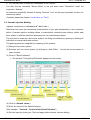
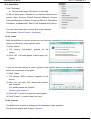
4.3 Gate
Click the icon “Gate” to get information about the connectivity between the runner segments and
the injection point.
Click “OK”. If all parts are properly connected, continue. Otherwise correct the runner
system.
Note: Open runner ends are colored red
resp. green, even if no dialogue is open
where runner end points can be digitized.
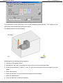
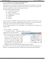
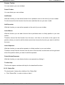
4.3.1 Define a gate location
If you have not built a runner system the following window will appear on the screen and
you can define one or more gate locations
without a runner system.
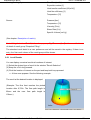
Gates appear on the screen as a yellow cone
on the part.
Example: Cup with one gate
Note: If you want to define more than one gate location, please consider chapter Virtual Runner
4.3.1.1 Enter the Gates
a) by a mouse-click
b) by keyboard
a) by a mouse-click
simcon kunststofftechnische Software GmbH
- 29 -
Cadmould® 3D-F
2012 / Version 6.0
Keep the <Ctrl> key pressed and click the location on the part where you want to gate it. The
coordinates of the gate will be indicated in the window "Gate Locations".
b) by keyboard
(1) Click "Add".
(2) Wait, until the window "Edit Gate Locations" appears on the screen.
(3) Indicate the coordinates as x, y, z components.
If the indicated point does not fit to the part surface, the desired gate
location will be projected onto the part surface in view direction.
(4) Click "OK".
Note: If you know two of three coordinates, you can leave the third coordinate empty. Cadmould® 3D-F will find it by itself.
You just have to put in a + or –, to define the direction from which Cadmould® 3D-F has to
drop a perpendicular onto the part surface. Eg: (14.5, 0, +) The input '+' will let the program drop
a perpendicular from the point (14.5, 0, Zmax) in negative Z-direction from above down onto the
part. If you want to define the gate on the bottom, you put (14.5, 0, -) in, without rotating the part
(which was necessary in earlier versions, because the projection of points in viewing direction
could find only visible points). Then the program will drop a perpendicular from the point (14.5,
0, Zmin) in positive Z-direction from below up onto the part.
4.3.1.2 Edit
(1) Mark the coordinates by clicking them.
(2) Click "Edit".
(3) Wait until the window "Gate Location" appears on the screen.
(4) Enter modified coordinates.
(5) Click "OK".
4.3.1.3 Delete
(1) Mark the coordinates by clicking them.
(2) Click "Delete".
simcon kunststofftechnische Software GmbH
- 30 -
2012 / Version 6.0
Cadmould® 3D-F
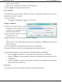
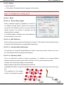
4.3.1.4 Optimizing the gate locations
Cadmould® 3D-F provides to you the
possibility, to optimize the gate locations
chosen by you.
Therefore, you have to activate the option
<Optimize gate locations> in the window
<Gate
locations>.
crossing
of
the
Cadmould® 3D-F
The
part>
option
<Permit
means,
that
involves the opposite
side of the part also. This could be helpful, if
you want to gate at a root of fin and does not
matter, on which side the gate is set.
The next step is choosing your options and
then click <Optimize> to start the gate optimization.
If you agree to the new locations click <OK>, otherwise click <Undo> to restore the old locations.
Note: The optimization can only be run, if the mesh of the part is already prepared.
4.3.1.5 Display Flow Length / Thickness
The function <Display Flow Length / Thickness> helps you to define the number of gates and
their positions. To use this function, you need a prepared mesh.
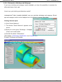
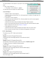
4.4 Sensors
(Optional)
The instruction “Sensors” offers the possibility of definition points on your part you want to proof
exactly. After execution of the simulation the defined “Sensors” appear as a result group in the
window “Result Selection”.
1) Click on the button “Sensor Editor”
The window: “Sensors” appears on the screen.
Keep the <Ctrl> key pressed and click on the
part where you want to position the “Sensor”.
The coordinates of the point are indicated in
the window. You may also enter the coordinates by keyboard.
Click <Add> to enter the coordinates by
keyboard.
Click <OK> to accept the “Sensor”.
simcon kunststofftechnische Software GmbH
- 31 -
2012 / Version 6.0
Cadmould® 3D-F
You can also edit or delete the coordinates of the “Sensor”.
You also find the command "Sensor Editor" in the pull down menu "Simulation" under the
instruction “Sensors”.
An alternative possibility instead of setting “Sensors” is to use the post processor function for
measuring results.
(Consider please the chapter “Local Value vs. Time”)
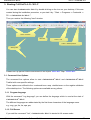
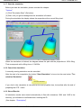
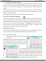
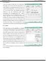
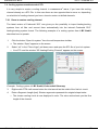
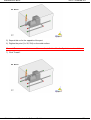
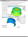
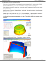
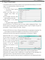
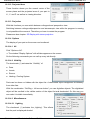
4.5 Cascade Injection Molding
(optional component to Cadmould® 3D-F Fill)
Weld lines can lower the mechanical characteristics of your part substantially or are a cosmetic
defect. Cascade injection molding allows to manufacture extended parts without visible weld
lines, and/or to shift the weld lines purposely into non restricted part areas.
The melt feed is made by a hot runner system, the filling is controlled by opening or shutting off
individual or several valve gate nozzles.
The packing pressure is applied by re-opening of the nozzles.
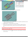
(1) Design a hot runner system.
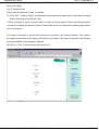
(2) Examine your hot runner system, by clicking on „Gate Editor“. Correct the runner system in
case of errors.
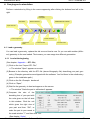
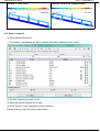
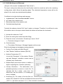
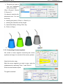
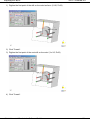
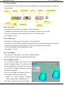
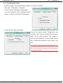
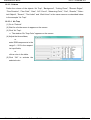
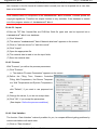
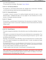
(3) Click on "Shutoff Nozzles".
The window "Timing Shutoff Nozzles" appears on the screen.
Clear table
Move up current line
Move down current line
Remove current line
Load values
Default values
Insert above current line
Test and apply table
contents,
dismiss
dialog
(4) Click on <Default values>.
(5) Enter the control of the Shutoff Nozzles.
(See example: "Cascade - Control of the Shutoff Nozzles")
(6) Exit the input by clicking on <Test and apply table contents, dismiss dialog>.
simcon kunststofftechnische Software GmbH
- 32 -
2012 / Version 6.0
Cadmould® 3D-F
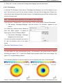
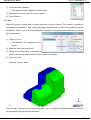
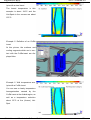
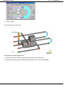
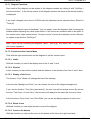
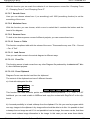
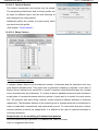
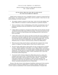
Example: "Cascade" part, runner system
Part
Runner system
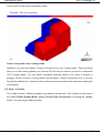
Controlling of the Shutoff Nozzles
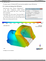
Example of a result
CP = Point of control
Points of control are a special usage of check points.
(See chapter: Check - Points)
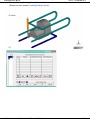
Example: “Cascade - Control of the Shutoff Nozzles”
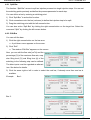
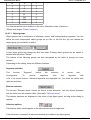
Column:
Description:
Line:
Line number
Designation:
The nozzle designation can be selected freely.
Segment:
The segments, which are to function as shutoff nozzles, can be selected with “Ctrl + Left
Mouse Button” on the runner system, or be registered automatically by clicking on <Default
values>. The segments are numbered automatically. They are marked red.
Action:
Single click on the button determine whether the shutoff nozzle should open or should close.
Control type:
The control type of the shutoff nozzle can be selected in the list field (column: Control type) by
mouse-click.
Point of control: Points of control can be selected with “Ctrl + left mouse button” on the part. Selected points of
control are marked red.
„Active line“:
The marking " > " on the left of the column "line" marks the active line.
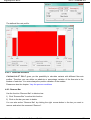
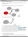
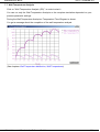
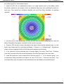
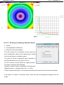
„Cascade“– example of a result shows the function of the following control.
= Nozzle open
= Nozzle close
Filling Time
=1s
Packing Time
=5s
simcon kunststofftechnische Software GmbH
- 33 -
2012 / Version 6.0
Cadmould® 3D-F
Line
Designation
Segment
Action
Control type
Parameters
Point of control
1
Nozzle 1
10
1 Time [s]
0.0
2
Nozzle 1
10
3 CP reached
2
3
4
5
6
7
8
9
10
11
Nozzle 2
Nozzle 4
Nozzle 2
Nozzle 4
Nozzle 3
Nozzle 5
Nozzle 1
Nozzle 2
Nozzle 4
11
14
11
14
12
15
10
11
14
3 CP reached
3 CP reached
3 CP reached
3 CP reached
3 CP reached
3 CP reached
2 Level [%]
2 Level [%]
2 Level [%]
2
2
1
1
1
1
99.0
99.0
99.0
Notice: The controlling of shutoff nozzles should always contain a line, which opens a shutoff
nozzle on the time = 0,0 s (see line 1) or with the level = 0,0 %, otherwise directly with the
beginning of simulation the flow front freezes.
Example: “Cascade - example of a result”
Process parameter:
Filling Time
=1s
Ejection Temperature
= 120 °C
Melt Temperature
= 250 °C
Packing Pressure
= 75 %
Hot Runner – Temperature
= 250 °C
Packing Time
=5s
Wall Temperature
= 40 °C
Pattern 1: Level 30%
Pattern 2: Level 51%
Pattern 3: Level 75%
Pattern 4: Level 97%
simcon kunststofftechnische Software GmbH
- 34 -
2012 / Version 6.0
Cadmould® 3D-F
Pattern 5: Level 100%
Pattern 6: End of the Packing Phase
4.6 Select a material
(1) Click "Material Selection".
The window "Cadmould® 3D-F material data base" appears on the screen.
(2) Find the material you want to use.
(3) Mark the desired material by clicking.
(4) Click "Select", if you marked the correct material.
Double-clicking in step (3) has the same effect.
simcon kunststofftechnische Software GmbH
- 35 -
Cadmould® 3D-F
2012 / Version 6.0
4.7 Define the process conditions
(1) Click "Process Parameters".
The window "Process Parameters" appears on the screen.
(2) Define the Filling Time, the Switch-to-Packing Level, the
Melt Temperature, the Hot-Runner Temperature, the Wall
Temperature and the Ejection Temperature,
or
click "Default", if you like to use proposed values for the
selected material,
or
click “Load”, if you like to see a selection of RM1/DES/SYMfiles which can be used for the actual project.
If it is possible, activate () the simulation of the packing phase and shrinkage and warpage prediction.
(3) Change the values, if you do not want to accept them.
(4) Click "OK", if you accept the modified parameters or continue to profile the injection in the
next section.
4.7.1 Vary the process conditions
You have the possibility to let Cadmould® 3D-F execute a Design of Experiment, where
Cadmould® 3D-F computes with different process conditions, which were defined by you
before. To use this function follow the next steps:
1) Click <Vary> in the window "Process-Parameters".
The window "Process Parameters" is extended by the column "Variation".
2) Enter always the positive variation of the median in
the new column.
e.g.: 0.2s with a median of 1s results a variation
between 0.8s, 1s and 1.2s of Filling Time.
3) When you click on "Go" (Simulation Start) after entering the "Simulation Description", a new folder is created, where all simulations of this DOE will be saved.
4) All simulations will automatically be written in the task
list, which will then be opened. Then you only have to
click "Go" in the task manager to start the calculation
in batch mode.
The simulation will only start automatically, if the module “Batch” is licensed. Otherwise you
will have to start the simulations from the created folder manually.
(Please see chapter: "Stack and compute projects")
simcon kunststofftechnische Software GmbH
- 36 -
2012 / Version 6.0
Cadmould® 3D-F
Note: The combination of N variables with 3 possible conditions, would cause 3^N simulations,
if proceeded naive. When using a method, developed by Mr. Taguchi, the number of necessary
simulations is reduced.
N
S
T
1
3
3
2
9
5
3
27
5
4
91
9
5
243
9
6
729
9
7
2187
9
So, if all 7 possible process parameters are varied, only 9 simulations are necessary instead of
3^7=2187 simulations of the naive way.
Note: You find the results of the variation in the menu <Results> under <Variation>.
(Please see chapter "Variation Results")
4.8 Flow Rate / Pressure Input Profile
1) Click “Process Parameters”.
The window “Process Parameters” appears on the screen.
2) Place the cursor on the button: “Filling Time [s]”.
The button changes to “Flow Rate / Pressure Input”.
3) Click this button.
The window “Flow
Rate
/
Pressure
Input” appears on
the screen.
In the window “Flow Rate /
Pressure Input” you see a
diagram describing your
injection process.
simcon kunststofftechnische Software GmbH
- 37 -
Cadmould® 3D-F
2012 / Version 6.0
4.8.1 Split Bar
The function: “Split Bar” serves to split an injection process into single injection steps. You can set
the switching points precisely and define the process parameter for each step.
You can define a bar by entering a switching point.
1) Click “Split Bar” to active this function.
2) Click somewhere onto the bar (red area) to define the injection step to be split.
3) Drag the switching point with the left mouse-button.
You can also active “Split Bar” by clicking the right mouse-button on the target bar. Select the
command “Split” by clicking the left mouse-button.
4.8.2 Edit Bar
You can edit the bars.
1) Click the right mouse-button on the bar area.
A pull down menu appears on the screen.
2) Click “Edit”
The window “Edit Bar” appears on the screen.
Now, you can edit the flow rate [cm3/s] and the
percentage [%] of the maximum flow rate, resp.
also filling level [%] and filling time [s] of the
switching to the following step can be defined.
The latter inputs must be regarded as alternatives. See below for details.
3) Click the arrow right or left in order to select the next bar, if already more than one bar is
availabe.
Example:
Bar 1:
Bar 2:
simcon kunststofftechnische Software GmbH
- 38 -
Cadmould® 3D-F
2012 / Version 6.0
Bar 3:
The defined flow rate profile:
4.8.2.1 Flow-Rate Variation
Cadmould® 3D-F gives you the possibility to calculate variants with different flow-rate
profiles. Therefore you can define an absolute or percentage variation of the flow-rate in the
window of each bar. You enter always the positive variation of the median.
Please see also the chapter: Vary the process conditions
4.8.3 Remove Bar
Use the function “Remove Bar” to delete a bar.
1) Click “Remove Bar” to active this function.
2) Click on the bar you want to delete.
You can also active “Remove Bar” by clicking the right mouse-button in the bar you want to
remove and select the command “Remove”.
simcon kunststofftechnische Software GmbH
- 39 -
Cadmould® 3D-F
2012 / Version 6.0
4.8.4 Clamping Force Limitation
Mark the field: “Clamping Force Limitation” to enter the parameters ( = On).
Enter the Maximum Clamping Force [kN] and the closing direction.
With this function you can try to run the last phase of the filling process without exceeding the
predetermined clamping force. The flow rate, respectively the pressure will be reduced. This
reslut can be used for a machine equitably fluting.
But please keep in mind a full supply safety while dimensioning the machine. Also a suggestive
packing pressure should be considered.
4.8.5 Injection Pressure Limitation
a) Mark the field: “Injection Pressure Limitation” to enter the parameters ( = On). Enter the maximum injection pressure [bar]. This pressure will not be exceeded no matter how the profile was
defined. For this option to trigger it does not matter at which moment of filling the pressure limit
is reached. In case the process runs below the pressure limit this option is not activated.
b) Define the filling level [%] at which the injection pressure is kept constant. This avoids pres sure peeks at the end of the filling process similar to switching to packing pressure. The
benefit of this option compared to a set pressure is that you need not know the exact pres sure.
4.8.6 Switch dep. on
Switch depending on the Time [s] or the Level [%] of filling by marking it (●).
The other scale will no longer be linear. Values given there are for information purpose only.
The same applies to the pop-up windows for editing the bars. During a simulation run using
compressibility material data (pvT) the non-active switch values may shift due to thermal shrinkage effects.
4.8.7 No inflow
With this option you can simulate a short shot. The filling stops at the entered filling stage.
Remark: You cannot simulate packing when this option is set, because the part must be full.
4.8.8 Pressure
Each step of the filling phase can be switched from a flow rate constant to pressure constant
step.
Right-click the bar of the step you want to change. Chose “Pressure” in the menu. The color of
the bar changes from red to blue. The scale relevant for pressures is at the right hand side of
the diagram. Switching back to a flow rate control is analogue.
simcon kunststofftechnische Software GmbH
- 40 -
2012 / Version 6.0
Cadmould® 3D-F
4.9 Heterogeneous Hot-Runner Temperatures
(1) From the pull down menu “Uniform Hot-Runner Temperature” choose the option „Hot-Runner Temperature“. Push the button “Input”.
Þ The window “Hot-Runner Temperature” appears
on the screen and the temperature distribution on
the hot runner segments is visible on the screen.
(2) You can now define a specific temperature for
every hot runner segment. For this you enter an
operator and an operand and select the segments
resp. the elements like described below:
- Runner segment:
Push the button “Runner Segment” to select segments which have been designed in Cadmould® 3D-F. Then you select the segments with Ctrl + left mouse button. You close the
selection with the right mouse button. Then you only have to apply the changes.
- Element select:
There is also the possibility to select triangle elements, which belong to a prepared runner sys tem in cfe-format. The elements have to be on negative groups to be recognized by Cadmould® 3D-F as runner system. The element selection is made using the selection tools
available on the status bar. The temperature assignment also has to be applied.
4.10 Wall Temperature Distribution
In Cadmould 3D-F you have different possibilities to define a wall temperature distribution.
This is amongst others depending on the modules you have licensed.
4.10.1 Uniform Wall Temperature
If you don't want to execute a wall temperature analysis or you haven't licensed the module
Cool, you can define a uniform wall temperature for the whole cavity.
This temperature is as well for the filling as for the cooling phase.
4.10.2 Assigned Wall Temperatures
You can assign wall temperatures manually.
(1) Click the button "Wall Temperature"
from the button bar.
The window "Wall Temperature" appears on the screen.
simcon kunststofftechnische Software GmbH
- 41 -
Cadmould® 3D-F
2012 / Version 6.0
(2) You can assign a temperature to every element
for the filling and cooling phase. Push the button
for the phase you want to assign a temperature.
(3) Chose an operator (=, +, -, x, /). This will be
applied to the area selected in the next steps.
(4) Give a value (operand) fitting your plan.
(5) Click “Element Select” or “Runner Segment”.
The window: “Wall Temperature“ disappears.
(6) Select the elements using the selection tools listed in the table SelectionTools or segments using CTRL+left mouse button.
(7) You can swap or copy temperatures by pushing the arrow buttons. Hold the mouse pointer
over the buttons to see what the effect of a click will be.
If you have assigned temperatures by this method, the wall temperature mode in the process
parameter window will switch to “Element-based WT for filling&cooling [°C]”.
4.10.3 Wall temperature analysis
If you have already done a wall temperature analysis or you will calculate it before the filling
simulation, you can use this distribution for the simulation.
1) Select "Element-based WT for filling&cooling [°C]" from the list.
2) (optionally) Click the folder button to load an already calculated distribution.
The window “Open” appears on the screen.
3) Open the appropriate TMP0 file.
If you like to use the wall temperature mode "Element-based WT for fixed times [°C]", you have
to choose at least one of the offered saving modes on the card "Snapshots" in the dialogue
"Options Wall Temperature Analysis". Cadmould® 3D-F will write additional results to the
known TMP files. The new CAR files have the identifier 152. They are read by the filling and packing simulation as well as by the shrinkage and warpage simulation instead of the old temperatures
for filling and cooling. The time dependent wall temperatures are shown with the wall temperature
dialogue.
(Consider please the chapters: Wall Temperatures; Options – Wall Temperature Analysis)
simcon kunststofftechnische Software GmbH
- 42 -
Cadmould® 3D-F
2012 / Version 6.0
4.11 Packing
(Not part of the module “Cadmould® 3D-F Fill”)
Conditions:
1. Material data include pvT data.
2. Cadmould® 3D-F Pack license.
In the menu “Process Parameter” define the duration of the packing phase [s] and activate the
check box “Packing Phase” ().
The packing pressure is a constant pressure by default. The value is dependent on the material.
To change or control these settings follow the next instructions:
1) Move the cursor to the button “Duration” near to packing.
The button changes to “Input”. Push this button and the window “Packing-Pressure Input”
appears on the screen.
2) Define a packing profile similar to defining an injection profile. The only difference is that
there is no flow rate input but a pressure input. It could be defined as absolute pressure val ues (blue bars) or relative to the required filling pressure (red bars). You can change this by
right mouse button on the particular bar and than choosing “Ratio [%]” or “Pressure [bar]”.
simcon kunststofftechnische Software GmbH
- 43 -
Cadmould® 3D-F
2012 / Version 6.0
Option: Open Hot Runner / Shutoff Nozzle
A large (hot-)runner system may preserve a pressure load beyond the end of the defined pack ing phase. This either can force further melt into the gating area (open system) or must unload
back towards the machine in case the nozzle is shut at its tip. Normally this has no significant
influence. If the gating is at a location that is critical for warpage and the material is still liquid,
however, this can have significant influence. In reality the hot runner is either closed by a needle
valve at the downstream end or has ambient pressure at the machine end. From now on both
options are simulated exactly. The choice is made via an alternative option during the “PackingPressure Input”.
Choices are:
Open Hot Runner = ambient pressure at the machine end of the runner
Shutoff Nozzle = zero flow rate at the tip(s) of the hot runner
4.11.1 Packing Variation
You can launch a DOE with different packing profiles. It works in the same way, as the flow-rate
variation. See chapter Flow-Rate Variation.
simcon kunststofftechnische Software GmbH
- 44 -
2012 / Version 6.0
Cadmould® 3D-F
4.12 S+W (Shrinkage and Warpage)
(Not part of the module “Cadmould® 3D-F Fill”)
The input cooling time determines the total fixation inside the mould as well as the remaining
cooling phase, which follows the packing phase. The calculated temperature course will be displayed in the results as extended packing phase.
Conditions to simulate shrinkage and warpage:
1. Cadmould® 3D-F Warp Expert license.
2. pvT data of the material used.
3. Mechanical data of the material used.
4. Calculated packing phase.
Typically the submenu below S+W “Input” needs no changes. Therefore it is sufficient to enter
the duration value in the input window beside the button and activate the checkmark.
1) Activate the check box “S+W”.
2) Enter the cooling time inside mold after filling.
3) Place the cursor on the button: “Duration [s]” near to “S+W”.
The button changes to “Input”.
4) Click this button.
The window “Shrinkage + Warpage” appears on the screen.
Enter the shrinkage and warpage process parameter:
Cooling Time inside mold after filling [s]
Heat Transfer Coefficient Ambient [W/m²/K]
Ambient Temperature [°C]
In the field "Simulation" of the window "Shrinkage and Warpage" calculation creteria can be
activated resp. deactivated:
Multiple Steps (more exact results, in addition, a
higher computing time, therefore optionally)
Unwarp Calculation – The deformation compensated geometry is saved in a extra file. To
calculate this file, it takes
more time. You
should only use this function, if a Unwarp-geometry is needed.
Anisotropy [%]: The values of the last fibre orientation file, needed for S+W are multiplied with this value/100%.
(100 % => calculation as before, 0 % => fibre orientation stochastical)
simcon kunststofftechnische Software GmbH
- 45 -
2012 / Version 6.0
Cadmould® 3D-F
To complete the field "Fix Surfaces" please see chapter "4.11.1 Fix Surfaces".
3) Click “OK”, in order to store the shrinkage and warpage process parameters.
4.12.1 Fix Surfaces
In the field "Fix Surfaces" of the window "Shrinkage and Warpage" you can fix surfaces of your
part. This can serve e.g. to fix the contact surfaces of the part with a steep inlay. Please con sider that all these elements will be fixed in space. So spatial disconnected fixed surfaces could
not move to each other.
Note: This function should generally only be used for ONE steep inlay.
Click the button "Duration/Input" next to the option "S+W" in the window "Process Parameters"
The window “Shrinkage+Warpage” with the function “Fix Surfaces” appears on the
screen.
You define the surfaces which should be
fixed with object groups. To define an
object group, click on "Element Select".
The window “Shrinkage + Warpage”
disappears from the screen.
You can now add the elements you want to
fix, with the selection tools to the object
group.
(See also: Table Selection Tools)
Note: You find a detailed description of object groups in the chapter: "Object Groups".
You can choose for every defined object group, if the elements in this group should be fixed by
activating the option "Fix". If there are already object groups defined from other dialogs, the
option "Fix" is deactivated by default.
In the following example on the next page you see a belt pulley with insert. (Pivot blanked)
Picture 1: Surfaces not fixed
Picture 2: Inner surfaces of the axle connexion are fixed
simcon kunststofftechnische Software GmbH
- 46 -
2012 / Version 6.0
Cadmould® 3D-F
4.13 Inserts (Simulation with Inserts or 2K-Simulations)
(The function Inserts is only available, if the module “2K & Insert” is licensed.)
By pushing the button “Inserts” you get a window where you can define the parameter for
inserts or first components in an insert or 2K-Simulation.
Note: To use this function it is necessary that for all parts (part as well as insert resp. first com ponent) the cfe-mesh is already prepared.
1) Push on “Inserts”.
2) The window “Inserts” appears on the screen.
3) Select “Insert”.
You can now define the
required data for the insert
resp. the first component.
Required
date
are
the
material and the initial temperatures, which can be
defined
in
the
following
ways:
Material:
• the
•a
material data can be entered manually or chosen from the table beside,
plastic or mould material from the Cadmould® 3D-F Material Database can be chosen
or
•a
material from a precedent project can be loaded (e.g. from the simulation of the first comp.)
Initial-Temperatures:
• define
•
a constant temperature as starting-temperature
load the starting-temperatures from a project, in the case the insert was also calculated with
Cadmould® 3D-F before. Therefore you need the interior temperatures, this means
Cadmould® 3D-F reads the last .car file with the number 132.
If you have made these input, you can leave the window with “Ok” and the checkmark in front of
“Inserts” will be activated.
Note: Please see also chapter Option-Inserts, as well as the Manual 2K & Insert.
simcon kunststofftechnische Software GmbH
- 47 -
Cadmould® 3D-F
2012 / Version 6.0
4.13.1 Boundary and Initial Conditions
●
On the contact surface there is ideal adhesion.
●
At the contact surface the insert and the part exchange heat.
●
At all other surfaces heat is exchanged with the mould.
●
The starting temperature for the insert is either constant or comes from an antecedent simulation.
●
If an insert consists of fiber reinforced material, the fiber orientation is read from a previous
Cadmould® 3D-F filling analysis.
●
The thermal stress is calculated inside the part and the inserts.
●
If a 2K simulation is calculated and a filling and packing analysis was done for the first com ponent, the thermal strains from before the ejection can be taken over to the calculation of
the second component. This happens, if in the dialog “Inserts” a temperature distribution for
the first part is loaded from a former simulation. This situation is given for a plate slide or
rotary mould. Because the first component is still under mould constraint and the strains
must be considered.
simcon kunststofftechnische Software GmbH
- 48 -
Cadmould® 3D-F
2012 / Version 6.0
4.14 Heat Transfer Coefficient
The heat dissipation at the plastic surface can be affected by different disturbances. Especially
inserts and over moulding of other bodys resp. sheets impair the cooling at the contact faces.
This affects always the cooling time, often the warpage behavior and sometimes the fill beha vior.
1) Click <Options>.
The window “Heat Transfer Coefficient” appears on the screen.
2) Determine the heat transfer coefficient for filling, packing
and after packing.
Filling phase:
(not available in Cadmould® 3D-F Rapid)
The heat transfer coefficient can be set optionally, wall thickness dependent or be given as constant value.
Packing and After Packing:
A constant value can be assigned to the heat transfer coefficient.
Heat Transfer Coefficient Element specific:
Activate the heat transfer coefficient
●
Element specific
The window “Heat Transfer Coefficient [W/(m²K)]” appears on the screen.
You can now assign the heat transfer coefficient
for every several element.
This heat transfer coefficient is effective for filling,
packing and after packing.
To change the heat transfer coefficient, you have
to choose the operator and operand first. Then
you can select one of the functions "Runner Segment" or "Element Select".
Function "Runner Segment":
1) Click the button "Runner Segment".
The window “Heat Transfer Coefficient [W/(m²K)]” disappears from the screen.
2) Now you can choose the segments, which you would like to assign a new heat transfer coefficient with
<Ctrl + left mouse button>.
simcon kunststofftechnische Software GmbH
- 49 -
2012 / Version 6.0
Cadmould® 3D-F
3) To return to the window "Heat Transfer Coefficient" click right mouse button and confirm the
changing.
Function "Element Select"
1) Click the button "Runner Segment".
The window “Heat Transfer Coefficient [W/(m²K)]” disappears from the screen.
The element selection is done with the selection tools from the table: "Selection Tools".
e.g.: tool: RECTANGLE
2) Hold the left mouse button pressed and describe the diagonal of a rectangle.
All elements which are completely included by the rectangle
are selected. You are
asked, if you want to change the heat transfer coefficient of these elements.
Limit the heat transfer coefficient
The calculated heat transfer coefficient can be limited by the function “Displayed Limits” and be
assigned with the key "Apply".
All elements with a lower heat transfer coefficient are set to the lower interval limit. All elements
with a higher heat transfer coefficient are set on the upper limit.
Heat transfer coefficient table
The button "Table" in the dialog "Heat Transfer Coefficient" opens a coefficient sorted element
table. By clicking the column-head, the table will be sorted after this column. Clicking one of the
elements in the table will show a blue cone on the element in the geometry.
Note: This cone can partial not be visible. To find the cone, zoom out of the part, until you see it,
because the cone, different of the part doesn’t changes its size.
Clicking an element on the part surface will move the table to this element in the list. You can
edit the heat transfer coefficients in this table. The option "Table" is not available in Cadmould® 3D-F Rapid.
Typical Heat Transfer Coefficients [W/m²K]
Metal
1000
Plastics
200
Sheet (compact)
200
Sheet (foamed)
100
Glass
50
simcon kunststofftechnische Software GmbH
- 50 -
Cadmould® 3D-F
2012 / Version 6.0
4.15 Injection Compression
If you want to use the process "Injection Compression" click on <Input> next to it.
The window "Injection Compression" appears on the screen.
Input all data required (eg Piston movement,
Velocity and group). The at first simulated velocity phase can be divided in multiple steps. That
applies also to the (optional) following force
defined phase. At least either a force or travel of
pistom limitation should be set.
When all inputs are made, you can activate the
process and use it for the simulation. The check
box is grey until you can set it.
The special process Transfer Mold can be found
in this window as well; here, the group of the preform and its temperature at the beginning must be defined. The input of a filling time in the pro cess parameters is necessary, but is overridden by the definition "No Inflow".
You can find new diagrams in the result selection after the simulation: Piston Travel, Piston
Velocity and Piston Force.
4.16 Describe and store the simulation.
(1) Click "Simulation Description" (ID button).
The window "Simulation Description" appears on the screen.
(2) Check the path and the directory, in which the results will be stored.
a) if you want to accept the path:
Go on with point (3).
b) If not:
1. Click "Browse".
The window: "Save as" appears.
2. Set the path and the directory.
3. Click "Save".
(3) Chose an identification number in the field "Result Identifier". (Usually simulations are given
ascending ID numbers)
(4) Enter a name for the simulation run in the field
"Title". This will appear with the results.
(5) (optional) Describe the simulation process in the
field "Description". This is stored to a text file for later access.
(6) Click "OK".
simcon kunststofftechnische Software GmbH
- 51 -
2012 / Version 6.0
Cadmould® 3D-F
4.17 Start the simulation
Before you start the simulation, please consider the chapter:
"Options"
(1) Click "Simulation Start" (Go button).
(2) Wait, until you get a message that the simulation is finished.
During the simulation the display shows the properties at the current filling level.
When the simulation is finished, the diagram shows the part with the properties at 100% filling.
That corresponds with a filling time of 1.34252s.
4.18 Cancel the simulation
A currently running simulation can be cancelled.
After the start of a computation the button "Start Simulation" is turns into the new button "Termination Simulation".
Termination Simulation
If you click it, the calculation is cancelled at the next possible time, but earliest after the end of
preparing the CFE - mesh.
4.19 Stored Results
All simulation results were stored automatically in files with extensions .RM1 and .CAR in the
directory you indicated or confirmed when entering the ID.
(See chapter: “Description”)
simcon kunststofftechnische Software GmbH
- 52 -
2012 / Version 6.0
Cadmould® 3D-F
5. Toolbar "Edit"
Activate the button: Edit
Pull down menu: View/Toolbars/Edit
Copy
Rotate
Mirror
Cut
Delete
5.1 Copy
You can copy all your parts, all runner segments and all Heating/Cooling segments.
You copy the parts by marking them, entering the direction and the amount of intermediate cop ies.
Take a look at the following example.
That is the goal.
5.1.1 Copy the part and the runner system
All coordinates can be defined by a mouse-click.
(See chapter: “Runner segment”)
1) Click the button "Copy".
The window "Copy" appears on the screen.
simcon kunststofftechnische Software GmbH
- 53 -
Cadmould® 3D-F
2012 / Version 6.0
2) Mark the parts you want to copy.
The parts you want to
copy are highlighted
red on the screen.
(Part 1, Runner 1, Runner
2, Runner 3)
You have to enter the displacement now. You can
do this by:
entering two points (<Point 1> <Point 2>) or
entering the direction and the length.
3) Leave the field by clicking <Tab> key.
4) Click on <Copy>.
5.1.2 Connecting all runner systems
We create a runner segment connecting two runner
systems and copy it to connect all the runner systems.
Open the function copy.
Mark the runner segment you want to copy, enter the
displacement by selecting “Point 1” and “Point 2”.
Enter the intermediate copies.
The goal is reached.
simcon kunststofftechnische Software GmbH
- 54 -
Cadmould® 3D-F
2012 / Version 6.0
5.2 Mirror
You can mirror all your parts, all runner segments and all heating/cooling segments.
You mirror the parts by marking them, entering a point on the mirror plane and the normal vector of the mirror plane.
Take a look at the following example.
This is the goal.
All coordinates can be defined by a mouse-click.
(See chapter: “Runner segment”)
In chapter: “Copy” we have created a runner system.
Now, we mirror the runner system in part. Mind not to mirror those segments on the backbone
of the runner system!
1) Click on "Mirror".
The window "Mirror" appears on the screen.
2) Mark the parts you want to mirror.
3) Enter an orientation point (<Point on
Plane>)
4) Enter the normal vector of the mirror
plane.
5) Leave the field by clicking <Tab> key.
6) Click <Mirror>.
The goal is reached.
simcon kunststofftechnische Software GmbH
- 55 -
Cadmould® 3D-F
2012 / Version 6.0
5.3 Rotate
You can copy all your parts, runner segments and heating/cooling segments around an axis.
You copy the parts by marking them, entering the axis, the angle and the intermediate copies.
Take a look at the following example.
This is the goal.
Again we start with the situation finished in chapter
“Second runner segment”
All coordinates can be defined by a mouse-click.
(See chapter: “Runner segment”)
1) Click the button <Rotate>.
The window “Rotate” appears on the screen.
2) Mark the parts you want to rotate, in this case all.
3) Enter a rotation axis by entering the axis direction and an axis point. The direction can be
taken from runner 2, the point may be defined by clicking on the end of the third runner seg ment.
4) Enter the rotation angle. Mind that 360° would put the final copy in the same place as the
source!
5) Enter the intermediate copies.
6) Leave the field by clicking the <Tab>
key.
7) Click <Rotate>.
The goal is reached.
simcon kunststofftechnische Software GmbH
- 56 -
Cadmould® 3D-F
2012 / Version 6.0
5.4 Delete
1) Click the button <Delete>.
The window “Delete” appears on the screen.
2) Mark the parts or runners you want to delete.
3) Click <Delete>.
5.5 Cut
With this function, models with a known symmetry could be halved. This makes it possible to
accelerate the simulation, with using symmetries, because only a half of the problem must be
calculated. There is no loss of presentation, because of the symmetrical definition, the whole
part is displayed.
1) Click on <Cut>!
The Window „Cut“ appears on the
screen.
2) Mark the parts you want to cut.
3) Define the cutting plane by entering a
point on the cutting plane and the normal vector to the plane.
4) Click on <Cut>!
Example: Cut into parts
After cutting, the parts can be edited separative, e.g. one half can be deleted and the other can
be duplicated with symmetrical definition.
simcon kunststofftechnische Software GmbH
- 57 -
Cadmould® 3D-F
2012 / Version 6.0
Additionally you have the possibility to cut the part into groups instead of separate parts. This
can be used for defining the thickness locally.
Example: Part cut into groups
Close to the points only / Cutting width
Additional you have the options “Close to the points only” and “Cutting width”. These functions
help you to edit cooling systems you load as STL file and you want to convert to a Cadmould
3D-F cooling system. You can divide connected channels where in the cavity a channel is
plugged. For this choose a “Cutting width” and the option “Close to the points only” to cut only
through the channel you choose by Ctrl and left mouse button and not all channels crossing the
cutting plane.
5.6 Undo – Function
The “Undo Function” makes it possible, to go back to the last state. This function can be used in
the masks Delete, Rotate, Mirror, Copy, Cut and Type Conversion by pressing the <Undo>
button. You can only go back one step.
simcon kunststofftechnische Software GmbH
- 58 -
Cadmould® 3D-F
2012 / Version 6.0
6. Design of a symmetrical cavity
In this chapter we show you the design of the following symmetrical multi cavity with the function
"Build symmetrical cavity".
Therefore, the runner system with cavity marked in the picture has to be designed yet:
We have now the following initial situation:
1) Click in the menu Edit / Geometry / Symmetry on „Build symmetrical cavity“.
The window "Build Symmetrical Cavity" appears on the screen.
Note: This window shows, that you are in a special mode to
build up a symmetrical cavity and has to be opened during the
whole design process. In this mode, there are only the functions "mirror", "rotate" and "delete" from the "edit" function bar available. You finish the design
process with the button "Done" and return to the normal mode.
2) Click the button "mirror" in the function bar.
The window "Mirror" appears on the screen.
3) Choose now the elements you want to mirror, define a point on the mirror plane and the nor mal vector of the plane.
simcon kunststofftechnische Software GmbH
- 59 -
Cadmould® 3D-F
2012 / Version 6.0
Mirror plane: As mirror plane we choose the plane spanned by the axes Y and Z. The normal vector of this plane is: X=1; Y=0;
Z=0
Point on Plane:: As a point on the
plane we choose the final point of the
third runner segment: X=23.299; Y=0;
Z=1
4) Click on "Mirror".
You can now see two symmetrical parts on the screen.
5) Close the window "Mirror".
6) Click the button "Rotate" in the function bar.
The window "Rotate" appears on the screen.
7) Choose the elements you want to rotate, define the rotation axis, a point on the axis and the
rotation angle.
Rotation axis: As rotation axis we define the
vector of the fourth runner segment. We
choose it by clicking the initial or final point
of the segment with <Ctrl + left mouse button>, while the cursor is set into one of the
fields for the rotation axis.
Axis Point: As point on the rotation axis we choose the final point of the third runner segment:
X=23.299; Y=15; Z=1
Rotation Angle: The rotation angle in this case is 180°.
8) Click on "Rotate".
You can now see the designed symmetrical multi cavity:
simcon kunststofftechnische Software GmbH
- 60 -
Cadmould® 3D-F
2012 / Version 6.0
9) Close now the window "Rotate" and leave the symmetrical cavity mode with the button
"Done".
Such a symmetrical design of a multi cavity decreases the calculating time significantly.
Note: You can control the design, by deactivating the option "Symmetrical objects" in the menu
view / options. You can see than the situation, without symmetrical objects.
6.1 Reconstruct w/o symmetries
Cadmould® 3D-F can also reconstruct the designed multi cavity without using symmetries.
1) Therefore click in the menu Edit / Geometry / Symmetry on "Reconstruct w/o symmetries".
Your reconstructed multi cavity appears anymore as follows on the screen:
simcon kunststofftechnische Software GmbH
- 61 -
Cadmould® 3D-F
2012 / Version 6.0
In your project exists now four parts and the complete runner system. Due to the fact that all
parts are now calculated separately, the calculation time can increase significantly.
Note: You can clarify that your project now consists of four parts by assigning a different colour
to each part in the menu View / Colours / Parts. (See also chapter: 16.3.3.4 Parts)
Your multi cavity appears than e.g. as follows on the screen.
simcon kunststofftechnische Software GmbH
- 62 -
2012 / Version 6.0
Cadmould® 3D-F
7. Toolbar "Wall Temperature"
Active the menu: Wall Temperature
Pull down menu: View/Toolbars/Wall Temperature
Heating/Cooling Channels
Heating/Cooling Circuits
Options Wall Temperature Analysis
Start Wall Temperature Analysis
H/C System from File
Save Heating/Cooling system
3D Cooling Channel
7.1 Mold
Click on "Heating/Cooling System".
The window "Heating/Cooling-Channel Segments" appears on the screen. You are on
the register "Mold".
To support you by designing a
heating/cooling system, you can
now define the dimensions of your
mold block. Therefore you can
define
the
coordinates
of
two
opposed corners or you can define
a minimal wall thickness between
part and mold wall.
You can now show or hide the
mold block with the button at the right.
Additionally you can display grid lines on the mold block and define the grid spacing.
The surface of the mold block can now be used as digitalising plane, for example to drill cooling
segments into the mold.
Please see also chapter: Drilling
Example:
simcon kunststofftechnische Software GmbH
- 63 -
Cadmould® 3D-F
2012 / Version 6.0
7.2 Heating/Cooling-channel segments
Click "Heating/Cooling System".
The window "Heating/Cooling-Channel Segments" appears on the screen. Jump to the
register "Bore".
To input a heating/cooling segment several data are necessary. These form the information of the vertices of starting
and ending point (color coded
red and green) as well as the
diameter. Bends and hoses are
tied to existing heating/cooling-channel segment by the
definition of a tangent.
There is more than one way to define these data.
Apply the method that fits your demands best. Edit fields are filled in automatically as soon as
they are redundant to your inputs. E.g. defining point 1 and the displacement to point 2 makes
the program fill in point 2, the length (L) and the direction.
Remark: Branches are possible.
7.2.1 Bore
Enter the coordinates of “Point 1” (red) and “Point 2” (green), the direction, displacement, the
diameter and length (L) of the bore H/C segment.
(See chapter: Select Function)
7.2.2 Bend
Enter the coordinates of “Point 1”
(red) and “Point 2” (green), the tangents and the connection to, the diameter and length (L) of the bend H/C
segment.
(See chapter: Select Function)
simcon kunststofftechnische Software GmbH
- 64 -
Cadmould® 3D-F
2012 / Version 6.0
7.2.3 Baffle
Enter the coordinates of “Point 1” (red) and
“Point 2” (green), the direction, displacement, the diameter and length (L) of the
baffle H/C segment.
(See chapter: Select Function)
Baffles are displayed striped white-purple.
Note: Baffles must be connected to two bore segments at the red end to be identified correctly by
Cadmould® 3D-F. If your baffles have the wrong direction for a correct connection, you can
invert the direction manually for every baffle by clicking the button with the red and green arrow
and applying with actualize. Or you can change the direction for several segments together on the
card "Type Conversion".
7.2.4 Bubbler
Enter the coordinates of “Point 1” (red) and
“Point 2” (green), the direction, displacement, the diameter and length (L) of the
bubbler H/C segment.
(See chapter: Select Function)
Bubblers are displayed striped white-green.
Note: Bubblers must be connected to two bore segments at the red end to be identified correctly
by Cadmould® 3D-F. If your bubblers have the wrong direction for a correct connection,
you can invert the direction manually for every bubbler by clicking the button with the red and
green arrow and applying with actualize. Or you can change the direction for several segments
together on the card "Type Conversion".
7.2.5 Hose
Enter the coordinates of “Point 1” (red) and
“Point 2” (green), the tangents and the connection to, the diameter and length (L) of
the hose H/C segment.
(See chapter: Select Function)
Hoses are displayed striped white - turquoise.
Note: Hoses are treated adiabatic. No heat transfer between other elements occurs.
simcon kunststofftechnische Software GmbH
- 65 -
Cadmould® 3D-F
2012 / Version 6.0
7.2.6 Type Conversion
All existing heating / cooling segments are administering in the Type Conversion mask.
Here you have the possibility to convert all
heating / cooling segments into the correct
type.
A diameter can be assigned to marked
heating / cooling segments.
This can be particularly helpful, if you
import complete heating / cooling systems
of IGES – files of axle center lines or Cadmould® 3D-F HCS – files.
(See chapter: Import Heating / Cooling systems as an IGES – file; H/C System)
The following segment types can be converted into:
bubbler into baffle or bore
baffle into bubbler or bore
bend into hose
hose into bend
7.2.7 Design Aid for Heating/Cooling Systems
7.2.7.1 Drilling
The segments "Bore", "Baffle" and "Bubbler" can now be designed easier. Therefore, you push
the button "Drilling". The register card is now displayed as follows:
In the new field you can now enter the distance between the end of the bore and the
part. Now move the cursor into the field
"red" point and digitize a point on the mold
block surface with "Ctrl + left mouse
button". From this point on will now be
drilled vertically into the mold. The drilling
depth (L) will be calculated automatically.
You only have to enter the diameter and
push "Create".
In the case, the bore don´t cut the part, it will be drilled until the opposite mold wall.
If you want to drill a bore which is not vertical to the mold wall, you can use the cutting plane
function and digitize on the cutting plane.
Then the bore is vertical to the cutting plane.
simcon kunststofftechnische Software GmbH
- 66 -
2012 / Version 6.0
Cadmould® 3D-F
7.2.7.2 Moving heating/cooling segments
It´s now possible to move heating/cooling segments by drag and drop in space. To do this,
select the segment with CTRL + middle mouse button. If you select the segment on the bound ary surface, you will move the whole segment. The direction in space and the length won´t
change.
If you select the end of a segment, only this end will move. Take care, direction and length of
the segment can change now. If two ends of segments are visibly together, they will be fixed
together, if you loose the button.
After the displacement, you have to click "Actualize" to accept the changes.
7.2.8 Repair of heating/cooling segments
If you import h/c-segments from IGES-lines it´s possibly that too short segments are generated,
which cause problems in the verification of the h/c-system. The function “Repair” helps you to
locate these too short elements. Push the button “Repair” and the following window will open:
You can now enter a value for the segment length. If Cadmould® 3D-F finds segments
which are shorter you can repair them automatically by pushing “Repair” . The segments which
are found are connected with lines with the “Repair”-window.
7.3 Heating/Cooling Circuits
You can define time-dependent flow rate- and inlet temperature values separately for each cooling circuit. Also every cooling channel could be assigned a cooling fluid of its own.
Click "Heating/Cooling Circuits".
The window "Heating/Cooling Circuits" appears
on the screen.
Cadmould® 3D-F recognizes automatically all exist-
ing heating/cooling circuits and numbers them. You can
now in the left table select one or more circuits, for which
you want to define the parameters. Chosen circuits are
displayed red on the graphic table.
If you have selected one or more circuits, you can now
enter the points of time with the associated values for
the flow rate and the inlet temperature into the table on
the right side. The time you enter defines, that from this
point of time until the next value resp. until the end of
process, the associated values are valid. A duly completed table could for example look like this:
simcon kunststofftechnische Software GmbH
- 67 -
Cadmould® 3D-F
2012 / Version 6.0
Now you only have to define a cooling fluid for each channel. You can do this by marking all, or
separately.
The big buttons in the first row under the table serve to delete the whole table, to handle several
rows of the table as well as to import/export the content of the table.
With the buttons in the next row you can show or hide the selected circuits, change the colour,
save one or more circuits, delete them and change the flow direction and the cooling fluid.
The buttons in the last row serve to activate the variation of flow rate and inlet temperature, to
change the unit of the flow rate, to load the data from another project as well as to accept or
reject the input.
7.4 Save Heating/Cooling system
All heating/cooling circuits can be stored in a file.
1) Click “Save Heating/Cooling System”.
The window "Save as" appears on the screen.
2) Enter the name of the heating/cooling system.
3) Select the file format. You have the option between
•
H/C System Files (*.hcs)
•
IGES Files (*.igs)
•
Cadmould-FE-Mesh Files (*.cfe)
•
NASTRAN Files (*.nas)
•
Binary Stereolithography Files (*.stl)
•
Textual Stereolithography Files (*.stl)
By default the *.hcs-format is selected.
If you decide to save the system as a *.cfe-file, the choice-dialog appears
<Center Line> means, that one element with two nodes will be saved.
<Surface> will save a triangulation of the channel surfaces.
4) Click "Save".
7.5 Import a Heating/Cooling System
1) Click “H/C System from File”.
The window "Open" appears on the screen.
2) Mark a HCS-file and click <Open>.
simcon kunststofftechnische Software GmbH
- 68 -
Cadmould® 3D-F
2012 / Version 6.0
H/C systems in the following file formats can be imported:
–
H/C system files (*.hcs)
–
IGES files (*.igs)
–
Cadmesh files (*.cm4)
–
CFE-mesh files
–
STL files
Please see for the import of STL files chapter: 3D Heating/Cooling Channel
7.6 Options – Wall Temperature Analysis
To start the wall temperature analysis the options of the analysis must be filled in.
Input is done, if you can close the window “Options Wall Temperature Analysis” by <OK>.
Note: You can find all input data from this dialog, except of "Snapshot" in the .TXT-file of the
project.
simcon kunststofftechnische Software GmbH
- 69 -
Cadmould® 3D-F
2012 / Version 6.0
7.6.1 Material
1) Click “Options Wall Temperature Analysis”.
The window "Options Wall Temperature Analysis" appears on the screen.
In the tab dialog: “Material” the Plastic Material and
the Mold Material have to be entered.
The Plastic Material should be already registered,
because you must have selected the plastic material of your part.
(See chapter: Wall Temperatures, Material)
Note: With the button "Load" you can optionally
load the settings for the actual card or for all cards
from an existing project.
2) Click <Mold Material>.
The material data base of metal appears on the screen.
3) Search for the mold material you want to use.
4) Double-click the material name or click <Select> to finish the selection.
(See chapter: Enter the material)
7.6.2 Cycle
In the tab dialog: “Cycle” you define the cycle time
of the wall temperature analysis.
simcon kunststofftechnische Software GmbH
- 70 -
2012 / Version 6.0
Cadmould® 3D-F
7.6.3 Heat Flow
In the tab dialog: “Heat Flow” you define the ambient temperature and the heat transfer coefficient of
the ambient of the wall temperature analysis.
Recommended default values are already set.
These values apply to the cavity in the auxiliary
processing time.
7.6.4 Element Length
In the tab dialog: “Element Length” you define the
element length of the mesh of the heating/cooling
channel. The shorter the elements, the more precise the results are, and the higher the computation
time. As a check the number of elements and the
proportional length of the elements to the channel
length is shown.
Attention: Small element lengths (analogical
much elements) causes long calculating time or
even memory requirements that exceed available
memory.
7.6.5 Simulation
In the tab dialog: “Simulation” you define the criteria of the termination of the wall temperature analysis. The criteria are associated by an OR-condition. The temperature condition compares every
location of two following cycles at the end of the
cycle.
simcon kunststofftechnische Software GmbH
- 71 -
2012 / Version 6.0
Cadmould® 3D-F
7.6.6 Snapshot
If you have chosen at least one of the offered saving modes, you can use the wall temperatures as
edge condition for following simulations in the dialogue “Process Parameters”. If you choose "Every"
or "For the fixed Times", this detailed results get
usable by the wall temperature mode "Element-based WT for filling&cooling [°C]".
Cad-
mould® 3D-F will write additional results to the
known TMP files. The new CAR files have the
identifier 152. They are read by the filling and packing simulation as well as by the shrinkage and
warpage simulation instead of the old temperatures
for filling and cooling. The time dependent wall
temperatures are shown with the wall temperature dialogue.
7.6.7 Inserts
This card offers you the possibility to consider
inserts from another material in your wall temperature analysis. The definition of the inserts is done
with object groups, which contain the elements of
another material. The object group must also contain the h/c-segments which belong to the insert. If
there are no elements or no h/c-segments in the
object group, you get an error message when starting the wall temperature analysis, that this insert is
ignored. If you still want to consider this insert, you
have to define an h/c-segment, which is nearby the
insert.
In the following example you see the results of two wall temperature analyses with inserts of different materials.
simcon kunststofftechnische Software GmbH
- 72 -
2012 / Version 6.0
Cadmould® 3D-F
Example 1: Wall temperature analysis with a steel insert
The lowest temperature in this
example is about 104°C and the
Hot-Spots in the corners are about
123°C.
Example 2: Definition of an Cu/Be
insert
At this picture, the surfaces and
cooling segments which are in contact with the Cu/Be-insert are displayed blue.
Example 2: Wall temperature analysis with a Cu/Be insert
You can see a clearly temperature
homogenisation
caused
by
the
Cu/Be insert at the ribbed region, as
well as a temperature reduction
about 25°C at the (former) HotSpot.
simcon kunststofftechnische Software GmbH
- 73 -
Cadmould® 3D-F
2012 / Version 6.0
7.7 Wall Temperature Analysis
Click on “Wall Temperature Analysis (GO)”, in order to start it.
You can run only the Wall Temperature Analysis or the complete simulation depended on your
process parameter settings.
During the Wall Temperature Analysis a Temperature-Time-Diagram is shown.
You get a message about the completion of the wall temperature analysis.
(See chapters: Wall Temperature distribution, Wall Temperatures)
simcon kunststofftechnische Software GmbH
- 74 -
Cadmould® 3D-F
2012 / Version 6.0
7.8 Cooling system manufactured of STL
It is very simple to create a cooling channel in Cadmould® 3D-F, if you have the cooling
channel already as a STL-File. In this case there are two opportunities to move on, depending
on what kind of cooling channel you have: close-to-contour or drilled channels.
7.8.1 Close-to-contour cooling channel
The latest version of Cadmould 3D-F now gives you the possibility to import heating/cooling
systems from stl files and convert them automatically into the internal Cadmould 3D-F
heating/cooling system format. The following example of a cooling system from LBC GmbH
describes how to operate.
1.
Click the button “Open h/c system” from the wall temperature toolbar.
The window “Open” appears on the screen.
2.
Select “.stl” in the “Files of type” pull down menu and open the STL-file of your h/c-system.
Your STL and the window “3D Heating/Cooling Channel” appears on the screen.
Example: Cooling system of LBC GmbH, Lüdenscheid Germany
3.
Digitize with CTRL+left mouse button the inlet as well as the outlet of the first h/c circuit.
4.
Enter a Segment-Length [mm]. Shorter segments represents the original shape better.
The chosen cooling circuit is now displayed in color. The color scale shows you the flow
length of the channel.
simcon kunststofftechnische Software GmbH
- 75 -
2012 / Version 6.0
Cadmould® 3D-F
5.
Click on the button with the green checkmark to start the conversion.
After the conversion you get the following display of the converted h/c-system:Now clear the
table with the button with the red cross.
6.
Repeat the steps 3. - 5. for all h/c-circuits of your h/c-system.
7.
After you have converted all circuits of your system, you only have to delete the STL file.
For this open the function “Delete”
from the icon bar “Edit” and delete the loaded STL
files.
Remark: H/C-Systems loaded as STL file appear in the menu delete as “Parts” and not as “H/CSegments”. So you have to delete “Parts”.
8.
Open the function “H/C Circuits”
from the button bar “Wall Temperature” to check the
system for failures.
simcon kunststofftechnische Software GmbH
- 76 -
Cadmould® 3D-F
simcon kunststofftechnische Software GmbH
2012 / Version 6.0
- 77 -
Cadmould® 3D-F
2012 / Version 6.0
You get the following display:
If there are no failures displayed in the window, the conversion was done correctly.
7.8.2 Drilled cooling channel
1. Click the button <File – Import – STL > and select the STL-File, which contains your cooling
system
2. The window to scale up your part appears. Unless otherwise requested, leave the setting to
mm and click <Ok>
Now, you have your cooling system in your Working Area.
3. Click the button <Edit – Geometry – Heating/Cooling Channel – Segments> and select in
the Status Bar <Point on Edge>
4. Click while holding the Ctrl-key on the edge-loop center of your cooling channel.
simcon kunststofftechnische Software GmbH
- 78 -
Cadmould® 3D-F
2012 / Version 6.0
Immediately the hole center (center mark on the mould surface), direction and diameter of the
hole appear in the dialog.
5. Enter a very high value for the length an click <Create>. The protruding ends will be cut
later.
6. Do the same with the transverse bore. The previous segment gets trimmed automatically.
7. Select the protruding end you want to delete by click on the segment while holding the CtrlKey. Then click the button “Delete”.
8. Finally you have to delete the imported STL. Therefore go to <Edit – Geometry – Tools –
Delete> select the STL-Part and click on “Delete”.
simcon kunststofftechnische Software GmbH
- 79 -
Cadmould® 3D-F
2012 / Version 6.0
7.9 Example of a heating/cooling system
During the construction of a heating/cooling system you should be sure about the dimension of
your part and the coordinate system origin you defined during the construction of your part at
the CAD-system.
For a new definition of the coordinate system origin consider please chapter "Transform".
A sketch of the part used in this example:
This is the goal.
Example: Loc3 with a runner system and a H/C system
1) Click "Heating/Cooling System".
The dialog "Heating/Cooling-Channel Segments" appears on the screen.
simcon kunststofftechnische Software GmbH
- 80 -
Cadmould® 3D-F
2012 / Version 6.0
The dimensions of the mold block were in this example already defined. The visibility of the
mold block was activated by pushing the button.
The display shows now the following:
Modelling the first heating/cooling segment:
1) Change to the register "Bore".
2) Activate the "red" point, by putting the cursor into one of the coordinate fields.
3) Enter the coordinates of <Point 1> (red). To get the coordinates of the second point, you can
either:
enter them directly,
enter the direction (e.g. by mouse click selection) and the length,
enter the displacement.
4) Enter the diameter of the bore segment.
simcon kunststofftechnische Software GmbH
- 81 -
Cadmould® 3D-F
2012 / Version 6.0
5) All parameters are given, when the <Create> button turns active. (Make sure, that all parameters are correct before you click <Create>.)
6) Click <Create> to get the segment on the screen.
Segments, that already exists (the input field for the segment number indicates “Existing” and a
segment is highlighted red.) can be updated or deleted.
You get the following result on the screen.
Next Segment:
1) Enter the coordinates of <Point 1> (red) by using the “Select Function”.
Note: To digitize points on the part, the mold block must be undisplayed.
(See chapter: Select Function)
simcon kunststofftechnische Software GmbH
- 82 -
Cadmould® 3D-F
2012 / Version 6.0
2) Get the coordinates of the second point, you can either:
enter them directly,
enter the direction (e.g. by mouse click selection) and the length,
enter the displacement.
3) Enter the diameter of the bore segment.
4) Click <Create>.
Next Segment:
5) Enter the coordinates of <Point 1> (red) by using the “Select Function”.
(See chapter: Select Function)
6) Get the coordinates of the second point, you can either:
enter them directly,
enter the direction (e.g. by mouse click selection) and the length,
enter the displacement.
7) Enter the diameter of the bore segment.
simcon kunststofftechnische Software GmbH
- 83 -
Cadmould® 3D-F
2012 / Version 6.0
8) Click <Create>.
9) Reactivate the display of the mold block.
Next Heating/Cooling Circuit:
The next circuit will be designed with the new design aid functions for heating/cooling circuits.
Therefore will first be drilled two bores through the part in X-direction.
1) Activate the function "Drilling" on the register "Bore".
2) Digitize the point on the mold surface where the drill should start.
(In this example: Y≈35; Z≈0)
3) All further input data will be filled in automatically, as you see in the next picture.
4) Click "Create".
simcon kunststofftechnische Software GmbH
- 84 -
Cadmould® 3D-F
2012 / Version 6.0
5) Repeat this no for the opposite of the part.
6) Digitize the point (Y≈-35; Z≈0) on the mold surface.
Remark: The cursor must be in one of the coordinate fields of the "red" point to create a dril.
7) Click "Create".
simcon kunststofftechnische Software GmbH
- 85 -
Cadmould® 3D-F
2012 / Version 6.0
Next Segments:
1) Digitize the first point of the drill on the mold surface. (Y≈35; Z≈32)
2) Click "Create".
3) Digitize the first point of the next drill on the mold. (Y≈-35; Z≈32)
4) Click "Create".
simcon kunststofftechnische Software GmbH
- 86 -
Cadmould® 3D-F
2012 / Version 6.0
The heating/cooling system is now shown like this:
Connection drill between the both upper segments:
5) Digitize the starting point of the drill on the side of the mold.
(X≈55; Z≈32)
6) Click "Create".
simcon kunststofftechnische Software GmbH
- 87 -
Cadmould® 3D-F
2012 / Version 6.0
You have now the following result:
The crossing drills were cut with each other and you can delete the superfluously segments
afterwards. Before we do this, we will connect the upper circuits with hoses.
1) Jump to the register "Hose".
2) Deactivate the display of the mold block.
3) Enter the coordinates of <Point 1> (red) and <Point 2> (green) by using the "Select Func tion" (Ctrl + left mouse button). Enter the diameter.
4) Leave the last field with the "Tab" Button.
Note: The direction of the tangents and the length of the hose will be calculated automatically by
Cadmould® 3D-F.
5) Click "Create".
6) Repeat the points 3) - 4) for the second hose.
simcon kunststofftechnische Software GmbH
- 88 -
Cadmould® 3D-F
2012 / Version 6.0
7) Click "Create".
The result looks now like this:
Deleting the superfluous segments:
1) Open the function "Delete" by pushing the button in the button bar.
2) Select the segments which should be deleted with "Ctrl + left mouse button".
simcon kunststofftechnische Software GmbH
- 89 -
Cadmould® 3D-F
2012 / Version 6.0
3) Click "Delete".
The goal is reached. Cadmould® 3D-F recognizes automatically all existing heating/cooling
circuits and numbers them.
simcon kunststofftechnische Software GmbH
- 90 -
Cadmould® 3D-F
2012 / Version 6.0
4) Click on “Heating/Cooling Circuits” to check the circuits and to enter the parameters.
(Please see also chapter: Heating/Cooling Circuits)
simcon kunststofftechnische Software GmbH
- 91 -
Cadmould® 3D-F
2012 / Version 6.0
8. Stack and compute projects
(Separate auxiliary module of Cadmould® 3D-F)
The "Cadmould® 3D-F Task Schedule" is a stand-alone program, which can be started
over the "Start"-menu of windows or in Cadmould® 3D-F by pushing the button "Cadmould® 3D-F Task Schedule". Several projects can be stacked and be computed success-
ively - also during your absence.
Use for it the Cadmould® 3D-F Task Schedule.
Note: The "Cadmould® 3D-F Task Schedule" can be started with user-specific settings.
Please see chapter "Command Line Options"
(1) Start the "Cadmould® 3D-F Task Schedule".
The window "Task User Credentials" appears on the screen.
If your scheduled simulations should be calculated while the registered user is not logged in,
you have to enter the password.
If not, you can continue without a password.
The window "Cadmould Task Schedule" appears on the screen.
The Cadmould® 3D-F Task Schedule always shows all Cadmould® 3D-F jobs
present in the memory ("task" directory) and their status.
If some Cadmould® 3D-F jobs had been stored, then these last in the Cadmould® 3DF Task Schedule listed as follows.
simcon kunststofftechnische Software GmbH
- 92 -
2012 / Version 6.0
Cadmould® 3D-F
Example:
Show system dialog
to edit task properties
Browser
Show Project
Terminate Task in current line
Clear Table
Move up current line
Remove current line
Move down current line
Start Task resp. batch in
current line immediately
Insert above current line
Column:
Job:
Description:
internal number; Several tasks (variant calculations) can be combined into one job, if they are to
be computed successively (starting status: Sequence).
Project:
Projects with full path information. (See chapter: Open)
Simulation:
Cadmould® 3D-F process simulation modules (can be switched on and off by mouseclick). Dependent on your defaults of the process parameters and your license process
simulation modules stand for you to arrangement.
T = Wall Temperature Analysis
(See chapter: Heating / Cooling - Circuits; Options – Wall Temperature Analysis)
F = Cavity Filling Analysis
P = Packing
W = Shrinkage and Warpage Analysis
The process parameters of fill -, packing -, shrinkage and warpage analysis, have to be stored
already assigning a project number.
(See chapter: Process; Description)
Date:
The date, at which the simulation is to be started.
Time:
The time, at which the simulation is to be started.
Starting mode:
Starting time
= beginning of simulation; new order knowing number (job)
Sequence
= the projects are processed in sequence.
Status:
Current conditions of the tasks (of the project).
simcon kunststofftechnische Software GmbH
- 93 -
Cadmould® 3D-F
2012 / Version 6.0
(2) Click on <Browser>.
The window "Open" appears on the screen.
(3) Mark a project and click on <Open>.
The project appears in Cadmould® 3D-F Task Schedule.
(4) Position the Courser (pointer of mouse) in the next free line and repeat the steps 2, 3, 4, to
all projects you would like to compute, until all of them stand in the Cadmould® 3D-F
Task Schedule.
(5) Give the starting date, the starting time and the starting mode,
or
you start the job in the current line immediately by clicking on <GO>
"Start Task resp. batch in current line immediately".
simcon kunststofftechnische Software GmbH
- 94 -
Cadmould® 3D-F
2012 / Version 6.0
9. Result selection
You can view and document results in several ways.
Click "View Results".
The window "Result Selection" appears on the screen.
Different Result Groups are available. In each group there are several Result Details.
Visible results can be varied and additional information displayed using the controls below these
selection fields.
simcon kunststofftechnische Software GmbH
- 95 -
Cadmould® 3D-F
2012 / Version 6.0
9.1 Result groups
Mind that depending on licensing and options selected for simulation the offered choice of result
groups may vary!
Result Summary
Cavity
Flow Front
Snapshot Filling
Filling Temperature (interior)
Filling Velocity (interior)
Filling Orientation Degree
Diagrams
Residual Stress
Miscellaneous
Part Quality
Snapshot Packing
Packing Temperature (interior)
Packing Velocity (interior)
Packing Orientation Degree
Shrinkage and Warpage - Cooling
Shrinkage and Warpage (Ejection)
Shrinkage and Warpage (Final)
Residual Stress in Layers –5 to +5
Wall Temperature Analysis
Heating/Cooling System
Sensor
Result files can be converted into text files.
(See chapter: Convert / CAR ->Txt)
simcon kunststofftechnische Software GmbH
- 96 -
2012 / Version 6.0
Cadmould® 3D-F
9.2 Result details
Mind that depending on licensing and material properties available the offered choice of result
details may vary.
Cavity:
Part without results
Flow Front:
Time When Filled [s]
Level When Filled [%]
Filled by Gate
Temperature When Filled [°C]
Pressure Loss [bar]
Shear Stress When Filled [kPa]
Velocity When Filled [mm/s]
Snapshot Filling:
Temperature [°C]
Pressure [bar]
Shear Stress [kPa]
Velocity [mm/s]
Frozen Layer Thickness [%]
Free Cross Section [mm]
Volume Shrinkage [%]
Filling Orientation Degree:
Averaged
Miscellaneous
Max. Temperature [°C]
Max. Shear Rate [1/s]
Diagrams:
Injection Pressure [bar]
Flow Rate [cm³/s]
Injection Power [kW]
Clamping Force X [kN]
Clamping Force Y [kN]
Clamping Force Z [kN]
Level of filling [%]
Mass [g]
Mass - Gate 1 [g]
Mass Flow - Gate [g/s]
Force Xn on object group [kN]
Force Yn on object group [kN]
Force Zn on object group [kN]
Moment Xn on object group [Nm]
simcon kunststofftechnische Software GmbH
- 97 -
2012 / Version 6.0
Cadmould® 3D-F
Moment Yn on object group [Nm]
Moment Zn on object group [Nm]
Residual Stress (element and node based):
Avg. Hydrostatic
Max. Von Mises
Part Quality:
Filling Problems
Sinkmarks
Ejection Time [s]
Sealing Time [s]
Freezing Time [s]
Gradient Volume Shrinkage [1]
Snapshot Packing:
(See the Snapshot Filling results.)
Packing Orientation Degree:
Averaged
Shrinkage & Warpage (Cooling):
Max. Temperature
Min. Temperature
Shrinkage and Warpage (Ejection and Final):
X-Deformation [mm]
Y-Deformation [mm]
Z-Deformation [mm]
Deformation [mm]
Shrinkage [%]
X-Warpage [mm]
Y-Warpage [mm]
Z-Warpage [mm]
Warpage [mm]
Curvature Change [%]
Filling Temperature (interior); Filling Velocity (interior)
Packing Temperature (interior); Packing Velocity (interior)
Residual Stress in Layers –5 to +5 without 0:
Avg. Hydrostatic
(Element based and node based)
Max. Von Mises
Wall Temp. Analysis Diagram:
Max. Temperature [°C]
Min. Temperature [°C]
simcon kunststofftechnische Software GmbH
- 98 -
2012 / Version 6.0
Cadmould® 3D-F
Heating/Cooling System:
Flow Rate [cm³/s]
Reynolds number [1]
Heat transfer coefficient [W/(m²K)]
Heat flow efficiency [1]
Temperature [°C]
Sensor:
Pressure [bar]
Temperature [°C]
Viscosity [Pa.s]
Shear Rate [1/s]
Specific Volume [cm³/g]
(See chapter: Description of results)
Note: Hitting the button “Detail”, information pops up. Eg: "Pressure [bar]" is the new default result detail of result group "Snapshot Filling."
The standard result detail is a user preference and will be saved in the registry. If there is no
entry, the first result column of the result group will be shown.
9.2.1 Local Results
You can display numerical results at locations of interest.
(1) Select the desired type of result in the window "Result Selection"
(2) Keep the <Ctrl> key pressed.
(3) Click the location of interest on the part and keep both keys pressed.
A blue cone appears. See the following example.
The result at the desired location is displayed.
(Example: The flow front reaches the picked
location after 0,752s. The flow path length is
85mm and the max. flow path length is
138mm.)
simcon kunststofftechnische Software GmbH
- 99 -
2012 / Version 6.0
Cadmould® 3D-F
9.2.2 Result Display
In the window for result selection there are scrollable buttons allowing to add or to modify the
selected result.
Air Traps
Sink Marks
Displayed Limits
Cavity
Orientation
3-Klick-Transformation
Deformation
Weld Lines
Further
Result
Clamping Force
Flow Direction
9.2.2.1 Air Traps
Click the button "Air Traps" in the window: "Result Selection".
The places, in which air traps may occur, are marked by small cones on the part.
The color of the cones can be modified by the user. The default is white.
(See chapter: “Colors”)
9.2.2.2 Weld Lines
Click the button "Weld Lines" in the window: "Result Selection".
The places, in which weld lines develop, are indicated on the part. Depending on the data quality there may be places with “false alarms”. It is up to the user to qualify this result.
The color of the lines can be modified by the user.
(See chapter: “Colors”)
9.2.2.3 Sink Marks
Click the button "Sink Marks" in the window: "Result Selection".
The sink marks on the part are displayed geometrically.
9.2.2.4 Displayed Limits
You can limit the range of the results by the
function: “Displayed Limits”. The limitation can
be accomplished with all results of the categories Flow Front, Snapshot, Miscellaneous and
Shrinkage & Warpage.
Here is one example of a limitation of the result: “Snapshot Filling Temperature [°C]”
1) Chose
the
result
category
„Snapshot
Filling“ and the result „Temperature [°C]“.
Each color is assigned a certain temperature.
simcon kunststofftechnische Software GmbH
- 100 -
Cadmould® 3D-F
2012 / Version 6.0
2) Click “Displayed Limits”.
The window "Displayed Limits “...“" appears on the screen.
In the left and right fields you see the range of
temperature occurring during the filling process (250°C to 263.1°C). It is the same range
of temperature that is shown in the large color
scale below the Menu Bar.
Now, you can limit the results in a range you want to view exactly by comparing the colors,
standing for different temperatures, on your part. Use the sliders or the input fields to set the
range boundaries. Clicking on “<” or “>” transfers the slider position to the input field allowing a
better tuning of the range.
Example: We view the range between 253.5°C and 256°C.
The limited results can be saved and recalled by clicking
<Save> and <Recall>, resp.. You cancel the limitation by clicking <Reset>.
9.2.2.5 Clamping Force
Click the button "Clamping Force" in the window:
"Result Selection" to get information about the clamping force [kN] and the projected area [mm²] depending on the clamping force direction. Mind that the results do not take account of undercuts.
If the button "Clamping Force" is pushed, the points
of load incidence are displayed with red, green and
blue arrows.
Please regard also chapter: Clamping Force
simcon kunststofftechnische Software GmbH
- 101 -
2012 / Version 6.0
Cadmould® 3D-F
9.2.2.6 Cavity
The button "Cavity" in the result selection dialog serves to display flow directions and orientations without result colors on the part. The arrows and fibers are visible more clear now. It is
possible to make an animation with this display option as well.
9.2.2.7 Flow Direction
Click the button "Flow Direction" in the window:
"Result Selection" to get
information about the flow
direction in any time of the
filling process. The time to
view is controlled by the
slider.
9.2.2.8 Orientation
Click the button "Orientation"
in
"Result
the
window:
Selection"
and
then on one of the buttons (red, yellow, green,
blue or magenta) standing for different layers.
Equal to the display of
directions of flow the orientation
may
change
throughout the process.
The time to view is controlled by the slider.
simcon kunststofftechnische Software GmbH
- 102 -
Cadmould® 3D-F
2012 / Version 6.0
9.2.2.9 Deformation (Shrinkage and Warpage)
If you have shrinking and warpage results available, you have the possibility to examine the
deformed shape of your part.
How do you get shrinking and distortion results?
Cadmould® 3D-F warp Expert user can calculate shrinkage and warpage. Shrink-
age and warpage results can be displayed as in the following example described.
Viewing distorted parts
(1) Click „Result Selection”.
The window “Result Selection” appears on the
screen.
(2) Select the result group “Shrinkage + Warpage
(Final)” and a result detail.
(3) Activate the button “Deformation”.
(See chapter: „Deformation Amplification“ and “Opacity [%]“)
Example: Shrinkage and Warpage
simcon kunststofftechnische Software GmbH
- 103 -
2012 / Version 6.0
Cadmould® 3D-F
9.2.2.10 3-Click Transformation
Note: This function is only available, if one of the result groups "shrinkage + warpage" is selec ted.
The 3-click transformation is just one of many possible procedures to temporarily define a trans formed coordinate system. The transformation may include a transformation of the origin of the
original coordinate system and a rotation of the coordinate axes.
(1) Select a shrinkage and warpage result.
(2) Click on “3-Click Transformation”.
The following window appears on the screen.
(3) Position the cursor in the first line.
(See Point on...function)
(4) Keep <Ctrl> pressed, and you
select three points on your part,
those you would like to assign the
characteristics of the respective
line (line inscription).
The cones can be stored only before the transformation.
To compare results of different simulation variants it is important to have the equal conditions to
each measurement.
In order to keep the conditions equal, the cones of the
"3-Click Transformation" can be stored and be loaded to measure a different simulation variant.
9.2.2.11 Shrinkage Allowance
The warpage-result (Result Group “Shrinkage + Warpage) can be calculated with anisotropic
allowance. You can define the orientation
of the new scaling system with entering 3
points (see 9.2.2.10 3-Click Transformation)
1. Select the result group “Shrinkage +
Warpage”.
2. As detail “Warpage” must be chosen.
3. Click on the “Shrinkage
Allowance”-
Symbol.
→ The window “Shrinkage Allowance”
appears.
simcon kunststofftechnische Software GmbH
- 104 -
2012 / Version 6.0
Cadmould® 3D-F
4. Enter a allowance in axial direction.
The "Default" button serves to set isotropic
shrinkage allowance based on the average
A description on how to enter coordinates
see chapter 3-Click-Transformation
longitudinal shrinkage as a starting point..
For the following picture a X allowance of
10% has been chosen and 0.8% for the other
directions.
As can seen quite clearly an anisotropic allowance (anisotropic stretching) is not angle preserving. Undercuts may arise and counter measures must be taken.
9.3 Interior results
In Cadmould® 3D-F Version 3.50 you can now see results from the inside of the part.
The results you can see are the following:
●
residual stress
●
filling temperature (interior)
●
packing temperature (interior)
●
filling velocity (interior)
●
packing velocity (interior)
In each Simulation the interior results at the end of the filling- and cooling phase are stored.
If you want more results to be stored please consider the following steps:
simcon kunststofftechnische Software GmbH
- 105 -
2012 / Version 6.0
Cadmould® 3D-F
9.3.1 Activating the results
Open the window “Simulation Options” before you start the simulation.
(Menu bar Simulation Options)
Jump to the tab “Shrinkage and Warpage”:
You can activate the result “Residual Stress –
Interior” to see this result after the simulation.
Jump to the tab “Optional Results”:
Choose the interior results “Temperature” and
“Velocity“ if you want to see them after the simulation for the whole process. The number of
“Stored Cross-Sectional Control Points” allows
you to adjust the resolution of the interior results.
Note: By default, Cadmould® 3D-F saves
the interior result at the end of the filling phase
and the end of S+V.
simcon kunststofftechnische Software GmbH
- 106 -
2012 / Version 6.0
Cadmould® 3D-F
9.3.2 Display of interior results
After executing a simulation with the settings as above you can now regard the interior results.
Open the result selection and select the group “Packing Temperature (interior)”.
Open the function “Cutting Plane” (Menu bar View Cutaway).
Activate now the cut by selecting a cutting direction and pushing the button “Active”.
You can now regard
the interior temperature distribution at any
point of time and in
any cutting plane. You
can also animate the
temperature developing.
Therefore
you
only have to push the
play
button
(green
arrow) in the button
bar.
The result detail has
no effect on the display of the interior
results.
The
only
effect is that the results of the chosen
layer are projected on
the shell of the part.
simcon kunststofftechnische Software GmbH
- 107 -
Cadmould® 3D-F
2012 / Version 6.0
Here are some more examples of interior results:
Figure: Filling Velocity (interior) with activated cutting plane
In the example above, the velocity was limited up to 400 mm/s to receive a better visibility of the
differences.
Figure: Residual Stress – Hydrostatic Node based with activated cutting plane
simcon kunststofftechnische Software GmbH
- 108 -
Cadmould® 3D-F
2012 / Version 6.0
9.4 Animation of cross-sectional profiles
Since one of our last updates you can regard cross-sectional profiles for some results in Cadmould® 3D-F. Now you can also animate these results in the form of a diagram.
Open therefore an existing project and choose the result “Temperature” from the result group
“Snapshot Packing”.
Make sure that in the menu “Display Options“ on the tab “Results“ the function “Cross-Sectional
Profiles” is activated.
Digitize now a point on the part with “Ctrl + left mouse button”. A diagram with the cross-sectional profile opens. You can now start the animation by pushing the play-button.
You can also jump to a point in time which you want to see with the slider in the window „Result
Selection“.
Figure: Cross-Sectional Profiles – Temperature Snapshot Packing
simcon kunststofftechnische Software GmbH
- 109 -
Cadmould® 3D-F
2012 / Version 6.0
9.5 3D flow front
The latest version of Cadmould 3D-F gives you the possibility to see a 3D flow front.
9.5.1 Activate the display of the 3D flowfront
Open the menu “View – Options – Miscellaneous”.
In the option “Transparency unfilled domains”
choose a value smaller than 100%. A value about
25% is advisable.
Now display one of the results “Time when filled” or
“Level when filled” from the result window and you
get a 3D flow front when you move the flow front by
slider or by entering a point in time.
Example of a 3D flowfront.
simcon kunststofftechnische Software GmbH
- 110 -
Cadmould® 3D-F
2012 / Version 6.0
9.6 Evaluation of multiple results
If you have run several simulations for a part, you can select the simulation results in the win dow "Result Selection" under the title: "Simulation".
(1) Click the arrow in the line: Simulation.
(2) Select a simulation by clicking it.
9.7 Loading New Results
If you want to open a different part with already existing results, click "Open" in the pull down
menu "File", or click on the first button in the toolbar.
(See chapter: “Open”)
simcon kunststofftechnische Software GmbH
- 111 -
Cadmould® 3D-F
2012 / Version 6.0
10. Description of results
10.1 Result Summary
By choosing the group <Result Summary> a window is opened, which contains a table with the
result developing over the time.
When you do a click on the title bar with the right mouse button, a configuration window opens.
There you can for example adjust the order and the visibility of the column. There can also be
loaded a standard configuration an own configurations can be saved and loaded.
10.2 Cavity
The geometry of your part without any result.
10.3 Flow Front
In <Time When Filled> and <Level When Filled> the filling pattern (isochrones) is stored. In
<Time When Filled> the time is stored, at which each point is reached by the flow front.
In <Level When Filled> the filling levels is stored, at which each point is reached by the flow
front.
Both filling patterns may be scaled using the slider and also may be animated.
In the ISO-Picture <Filled by Gate> you can see the influence of the different gates. The melt of
each gate will be displayed in an own color.
In case of using cascade filling it is process conditional possible that the filling operation of following gates is unrealized.
<Temperature When Filled [°C]> holds the temperature of the melt at the time of each point
being reached by the melt front, i.e. here the flow front temperatures are stored. The displayed
temperatures are average values across the part’s thickness.
<Pressure Loss [bar]> indicates the pressure loss from the point of injection to the respective
place at the time of 100 % filling (the maximum if more than one injection point was defined.).
<Shear Stress When Filled [kPa]> contains the shear stress at the flow front. The maximum
shear stress over the thickness usually occurring close to the wall or the frozen skin is given.
<Velocity When Filled [mm/s]> represents the flow front speed, when the flow front reaches the
location you are looking at.
simcon kunststofftechnische Software GmbH
- 112 -
Cadmould® 3D-F
2012 / Version 6.0
10.4 Snapshot Filling
The category <Snapshot Filling> contains snapshots, i.e. here values at specific times during
filling are stored. The time can be set by the slide control in the result menu. In addition the results can be animated.
The following results are available:
<Temperature [°C]>:
The average temperature across the parts thickness (wall to wall).
<Pressure [bar]>:
The current pressure at each location of the part.
<Shear Stress [kPa]>:
The maximum shear stress across the thickness at each location of the part.
<Velocity [mm/s]>:
The average velocity across the parts thickness.
<Frozen Layer Thickness [%]>:
The thickness of the frozen layer as percentage of the parts thickness.
<Free X Section [mm]>:
The thickness of the flow able layer.
<Volume Shrinkage [%]>:
The volume shrinkage is the shrinkage potential of the plastics melt at a specific moment during
filling and packing phase. The volume shrinkage contains beside the linear shrinkage also the
gauge shrinkage. That's why the values can be comparatively high compared to the processing
shrinkage. Volume shrinkage differences in the part causes different local shrinkage, what
causes warpage.
10.5 Filling Orientation Degree
The average orientation degree can be displayed as an “iso image”. The values are between 0
(coincidental) and 1 (reliable). You can recognize, where isotropic and anisotropic areas are in the
part. You can draw first conclusions about the stiffness and shrinkage behaviour from this
information. Building the average of the layers is done from the orientation tensor. The average
direction can be checked by activating all five fiber buttons. Instead of the colored fibers you can
see one black fiber.
simcon kunststofftechnische Software GmbH
- 113 -
2012 / Version 6.0
Cadmould® 3D-F
10.6 Force and Moment
The following results are displayed on the part:
●
Resulting Force [kN]
●
Moment Xn on object group [Nm]
●
Moment Yn on object group [Nm]
●
Moment Zn on object group [Nm]
The value of the respective result refers to the moment chosen in the result selection window.
The development of force and moment can also be saved as animation.
Note: The arrow of the respective moment is only displayed, if the moment has a certain influ ence on the result. Is for example the moment in X-direction negligible small, only the other
moments are displayed.
(Please see also chapter: "Force and Moment (Display)")
10.7 Diagrams
This category contains nine diagrams:
(Injection) Pressure [bar] vs. time [s]
Flow Rate (at the gate) [cm3/s] vs. time [s]
Mass [g] (contains also the runner system
with hot runners)
Clamping Force X [kN] vs. time [s]
Mass - Gate [g]
Clamping Force Y [kN] vs. time [s]
Mass Flow – Gate [g/s]
Clamping Force Z [kN] vs. time [s]
Force Xn; Yn; Zn on object group [kN]
Level (of filling) [%] vs. time [s]
Moment Xn; Yn; Zn on object group [kN]
Example: Pressure [bar] vs. time [s]
Note: When the option "Local Value vs. Time" in the menu View, Options, Results is activated,
there are more diagrams available.
(See chapter: "Local Value vs. Time")
simcon kunststofftechnische Software GmbH
- 114 -
Cadmould® 3D-F
2012 / Version 6.0
10.7.1 Diagram Functions
Each result of the diagram can be probed in the diagram window by clicking it with “Ctrl/Strg +
left mouse button”. In the left top corner of the diagram window the result at the desired location
is displayed.
If you load a diagram curve from a CAR file also the abscissa can be selected freely. Default is
"Time [s]".
Zoom curves without input via keyboard: You can simply zoom the diagrams with a rectangular
window without selecting any other option before. If the curves are zoomed, there is an option in
the context menu (right mouse button) "Unzoom curves" to show the complete curves. Alternative option is the shortcut "Ctrl/Strg+F”.
Note: There is a line connecting the diagrams "Mass – Gate n [g]" and "Mass Flow – Gate n [g/s]"
with runner segment n.
10.7.2 Functions in the Context Menu
Click with the right mouse button on the diagram to call the context menu.
10.7.2.1 Limits
With this function you can fit the display area of the X- and Y-Axis.
10.7.2.2 Division
In this function you can set the number and the distance of the divisions from the X- and Y-Axis.
10.7.2.3 Display of the Curve
The function “Font” allows it to change the font of the labeling.
In the function “Background Color” you can choose the color of the diagram background.
If you use the function “Text Color (permanent)”, the text color will be always as set. By choose
function “Text Color = Curve Color”, the text color will always be the same like the curve color.
In the functions “Curve Color” and “Pen Width” you can set the display options of each curve.
10.7.2.4 Delete Curve
With this function you can delete several curves of the diagram.
10.7.2.5 Curve to the bottom
With this function you can sort the curve to the bottom of the list on the right hand side.
simcon kunststofftechnische Software GmbH
- 115 -
2012 / Version 6.0
Cadmould® 3D-F
10.7.2.6 Scale Like Active Curve
With this function you can scale the ordinate of not homonymous curves like “Clamping Force
X”, “Clamping Force Y” and “Clamping Force Z”.
10.7.2.7 Smooth Curve
Here you can choose values from 1 (no smoothing) until 1000 (smoothing function) to set the
smoothing of the curve.
10.7.2.8 Maximize Curve
With this function you can choose, which curve is scaled that it contacts the bottom and the
head of the diagram.
10.7.2.9 Rename Curve
To look at two homonymous curves of different projects, you can rename them here.
10.7.2.10 Curve => Table
This function compiles a table with the values of the curve. This saves the way over “File – Convert
– Car Text”.
10.7.2.11 Load Curves
Here you can load curves in the actual diagram in different ways.
10.7.2.11.1 From File
This function serves to load curves from any other Diagram-file produced by Cadmould® 3DF, also of different projects.
10.7.2.11.2 From Clipboard
Diagram-Curves can also be load from the clipboard.
The content of the clipboard can have 2 different formats:
a) A text with data pairs like this:
5
10
15
1363
1377
1397
or
5
1363
10
1377
15
1397
This function can read decimals, points and commas without problems: "1" = "1.00" = "1,00"
Additional you can mark a table in MSExcel and copy the content with Strg/Ctrl+C to the clipboard.
b) A second possibility is to load a bitmap from the clipboard. For this you need a program which
can copy images to the clipboard. Any image editor should be able to do this. It is possible to load
cutaways from an image as well. If it is not possible to load an image, the reason can be, that there
is too much useless image information in the image. In this case you can erase these labels,
simcon kunststofftechnische Software GmbH
- 116 -
2012 / Version 6.0
Cadmould® 3D-F
legend or scale using eg MSPaint. If there are gaps in the curve, Cadmould® 3D-F cannot
read this as one curve. You have to stitch it with a few pixels first (in your image editor).
To decide between the curves, Cadmould® 3D-F needs different colors. Possibly you have to
repair that, too.
10.7.2.12 Variation
This function allows you to load the bar charts or compare curves of an variation, if performed.
10.7.2.13 Store Image File
With this function you can save the diagram window as PNG- or BMP-file.
10.8 Residual Stress
Avg. Hydrostatic
Max. Von Mises
This results can also be displayed as diagram over the profile. Digitize <Ctrl + left mouse but ton> a point on the part to see the diagram.
10.9 Part Quality
Points which are difficult to fill can be recognized with the result <Filling Problems>.
There are four categories:
green
=
good to fill
yellow
=
problems with the filling are likely
red
=
there are problems with the filling
white
=
not filled
Criteria are comparison of flow front and melt temperature as well as comparison of filling time
and sealing time.
For the analysis of <Sink Marks> the sealing time is compared with the time of freezing.
The <Ejection Time [s]> is the time when the average temperature reaches the ejection temperature.
<Sealing Time [s]> means every connection to a gate is frozen.
<Freezing Time [s]> means the time at which the entire cross section has reached the no flow
temperature.
The <Gradient Volume Shrinkage> describes the quality of the sink marks. It´s hundred of times
the gradient of the thickness shrinkage. The gradient expresses, how much the reflected light is
simcon kunststofftechnische Software GmbH
- 117 -
Cadmould® 3D-F
2012 / Version 6.0
distorted, respectively casts a cloud. A high value describes a great changing of the surface direction in comparison to the design. If the part is comparative planar at this point, you can see a
sink mark or a buckle there. By our experiences this is the case, if the value is higher then 3.
10.10 Snapshot Packing
See chapter: "Snapshot Filling"
Note: During the remaining cooling time, Cadmould® 3D-F will continue writing 111-files.
The packing time will be extended up to the ejection time.
10.11 Shrinkage & Warpage - Cooling
The max. and min. temperature occuring in the mold [°C] over the time [s].
10.12 Shrinkage & Warpage (Ejection)
Results describe the state outside the mold immediately after ejection from the mold.
This category comprises these results:
X-Deformation [mm]
Y-Deformation [mm]
Z-Deformation [mm]
Deformation [mm]
Shrinkage [%]
X-Warpage [mm]
Y-Warpage [mm]
Z-Warpage [mm]
Warpage [mm]
Curvature Change [%]
The first 4 deformation results are the components and the overall values of deformation based
on shrinkage and warpage.
The <shrinkage> is the local linear change in distance in the part, occurring in the surface
extension. It is not directed, i.e. directional differences as they are typical for fiber reinforced
materials are displayed as average values. The mean shrinkage of the entire part is given in the
status line.
The <warpage> is the overall deformation reduced by the above defined mean shrinkage.
Except the local shrinkage all deformation results depend on the position of the warped part and
the original one. For the standard the mean deformation is minimized. The relative position can
be changed using the 3-Click Transformation.
simcon kunststofftechnische Software GmbH
- 118 -
Cadmould® 3D-F
2012 / Version 6.0
The <curvature change> is used by curved faces and free formed surfaces, which could not be
measured normally. A positive result describes a convex deformation, a negative result
describes a concave deformation.
10.13 Shrinkage & Warpage (Final)
The results show the state outside the mold after cooling down to the ambient temperature
entirely.
This category holds the same types of results as the category “Ejection” described above.
10.14 Interior
At the interior results, a result is assigned to every node depending on the time. These result
distribution can also be displayed as a diagram over the profile or on cutting planes.
To see this diagram, you have to digitize a point on the part with <Ctrl + left mouse button>.
The following interior results are available:
●
Filling Temperature
●
Filling Velocity
●
Packing Temperature
●
Packing Velocity
The wall thickness of the part is divided into 10 layers. That means 10+1 check points. Time-dependent-temperature or -velocity is assigned to each check point.
Please see also chapter: Cross-Sectional Profiles
10.15 Residual Stress Interior
The remaining Hydrostatic Stress and the remaining Von Mises Stress after cooling to ambient
temperature. These results can also be displayed as cross-sectional profiles. Digitize a point on
the surface of the part to show this profile.
10.16 Wall Temperature Analysis
The max. and min. temperature at the mold [°C] over the time [s], as well as the inlet and outlet
temperature and the flow rate for each cooling circuit can be displayed in a diagram.
simcon kunststofftechnische Software GmbH
- 119 -
Cadmould® 3D-F
2012 / Version 6.0
10.17 Heating/Cooling System
The <Pressure [bar]> describes the pressure at each point of the System.
The <Reynolds number [1]> (Re) is a dimensionless number, which describes the ratio between
the inertia and viscosity forces. For the pipe stream accounted here, it is:
Re = average speed * diameter / kinematic viscosity of the fluid
If the Re number decreases below a critical threshold of approx. 2300, the favored turbulent
flow switches to a laminar flow, which can dissipate much less heat from the cooling wall. The
Re number and further typical numbers are necessary for the calculation of the heat flow to the
coolant fluid.
Because of obstructions and fluctuations are not allowed to have influence on the heat flow, the
Re number should be high enough over the threshold. With rising value there is a repletion of
the impact, so that an increase produces nearly no advancement, but requires a higher pump
capacity.
The <Heat transfer coefficient [W/(m²K)]> describes the temperature transfer between the mold
and the coolant fluid.
The <Heat flow efficiency [1]> shows if an element takes surpassing or substandard much of
the whole heat supplied. The whole length of the system is accounted.
E<1 The element absorbs substandard much heat
E=1 The element absorbs average much heat
E>1 The element absorbs surpassing much heat
That means, that the system is balanced designed, if all elements have the efficiency 1.
The <Temperature [°C]> shows, where and how the temperature of the temperate medium
arises. A coolant bore, whose medium heats much, dissipate much heat and is perhaps too
small dimensioned.
simcon kunststofftechnische Software GmbH
- 120 -
Cadmould® 3D-F
2012 / Version 6.0
10.18 Sensor
The category <Sensor> contains five diagrams:
●
Pressure [bar] vs. time [s]
●
Temperature [°C] vs. time [s]
●
Viscosity [Pa·s] vs. time [s]
●
Shear Rate [1/s] vs. time [s]
●
Specific Volume [cm³/g] vs. time [s]
Check-Point-Diagrams and Check-Points are connected by a line.
Each result of the diagram can be probed in the diagram window by clicking it. In the left top
corner of the diagram window the result at the desired location is displayed.
simcon kunststofftechnische Software GmbH
- 121 -
2012 / Version 6.0
Cadmould® 3D-F
11. Variation Results
If you've used the "Vary" function in the dialogue "Process Parameter" or another variation
method (DOE), you can see the results after the simulation in the menu "Results → Variation”.
Note: The variant calculations are only made automatically, if the module “Batch” is licensed.
Otherwise you have to start all necessary variant simulations manually.
11.1 Summary
When you choose the function "Summary", the
window "Variation Summary" appears on the
screen.
In this window you can see, which parameters are
varied and which process parameters has which
simulation ID.
11.2 Bar Charts
When you choose the function "Bar Charts", the
following variation bar charts appears on the
screen. On the right hand side, you can choose,
which result you want to display. The numbers in
the bars accord to the simulation ID.
11.3 Compare Curves
When you choose the function "Compare
Curves", a diagram appears on the
screen, where you at first have to choose
the value for the X- and Y-axis in a separate window.
On the right hand side, you can choose
to which simulation the axis will be
scaled.
simcon kunststofftechnische Software GmbH
- 122 -
Cadmould® 3D-F
2012 / Version 6.0
12. Examples of the results
You find the result: "Time When Filled" in the result category "Flow Front“. This result shows
isochrones of the flow fronts during filling. Each color is assigned to an equal long time range
depending on the number of colors in the scale.
e.g.: the color blue is assigned to the time range 0.000 – 0.0168s, the time 0.83s is shown in
the last red color that encloses 0.824 – 0.841s.
You can detect potential problems due to weld lines or air traps in this presentation.
(See chapter: "Weld Lines", "Air Traps")
This picture shows the current packing pressure at each point of the part. The time can be set
either with the slider or by numeric input in the time field above the slider. For filling snapshots
there is the additional choice of numeric input of the filling level.
simcon kunststofftechnische Software GmbH
- 123 -
2012 / Version 6.0
Cadmould® 3D-F
The diagram shows the maximum temperature at the end of the filling phase for each place /
point at the part. (Color scale set to 14 colors for better reading)
A filling simulation of a whistle was run to show the following results.
The result shows an air trap
at the round wall. An air trap
can lead to the so-called
“Diesel effect” and burn the
material. Obviously, the flow
front is slower in the round
wall than the flow front in the
cylinder
wall,
this
is
the
reason for the air trap. In
order to increase the flow
front speed in the round wall,
the wall thickness is changed.
(See chapter: “Thickness”)
simcon kunststofftechnische Software GmbH
- 124 -
Cadmould® 3D-F
2012 / Version 6.0
The air traps and weld lines can be indicated.
The next picture shows the result of a simulation, after the wall thickness was changed from
1mm to 1.5 mm. The air trap at the round wall is avoided.
simcon kunststofftechnische Software GmbH
- 125 -
2012 / Version 6.0
Cadmould® 3D-F
12.1 Example: Force and Moment
In the following example, the force and the moment on the slider in the clamping should be cal culated.
(See also chapter "Force and Moment (View)" and "Force and Moment (Simulation)")
This picture shows the cavity with the selected inner
surfaces and the defined
coordinate
system.
the
upper inner surface is also
selected, but because of
perspective
reasons
not
visible.
In the following pictures you see the display of the results:
Picture 1: Result of the calculation of force and moment
Note: Only the moment in X-direction is displayed, because the others are negligible low. As
result of the forces is only displayed the resulting force.
simcon kunststofftechnische Software GmbH
- 126 -
Cadmould® 3D-F
2012 / Version 6.0
Picture 2: Force in Z-direction over the time
You can see this diagram for all three directions, as also for the moments in all three directions.
(See also chapters: "Force and moment (Description of results)" and "Diagrams")
simcon kunststofftechnische Software GmbH
- 127 -
2012 / Version 6.0
Cadmould® 3D-F
13. Animations
13.1 Online Animations
You can animate all results in the categories: "Snapshot Filling", "Snapshot Packing" and the
results: "Time When Filled" and "Level When Filled" in the category "Flow Front".
(see chapter: “Description of results”)
For playing an animation use the keys "Play", "Pause" and "Stop" or use the button in the
menu bar.
(see chapter: “Button Bar”)
Before you play an animation consider please the chapter:
"Results, Animation Frames"
13.2 Single-Step Frames
In the window "Result Selection" you can look at single results in each stage of the injection
molding process. You can determine the time and the filling level by keyboard or mouse.
by keyboard
define the time
define the filling level
(1) Mark the field "Time [ s ]".
(1) Mark the field "Level [%]".
(2) Enter a time value.
(2) Enter the filling level between 0 - 100.
(3) Press "Return".
(3) Press "Return".
adjust the slider
by mouse
(1) Drag the slider. Resting for a short period will let the display adjust to the time position.
by keyboard
(1) Position the cursor on the slider
(2) Shift the slider using the ←/→ keys.
Example: 1
Picture shows the average temperature at
a filling level of 97%.
simcon kunststofftechnische Software GmbH
- 128 -
Cadmould® 3D-F
2012 / Version 6.0
13.3 Store Animations
You can store every animation as an avi-file. You can insert these into your reports, presentations
etc. and run it with the appropriate software, e.g. Microsoft’s Media Player. It is not possible to view
the stored animations with Cadmould® 3D-F.
Alternatively animations can also be saved as a sequence of pictures. Therefore you can
choose BMP or PNG as file format.
The result is a sequence of picture-files like this example:
"Movie_00000000.bmp"
"Movie_00000001.bmp"
"Movie_00000002.bmp"
...
The function "File -> Convert -> BMP/PNG -> AVI" allows you to convert such a sequence into
an AVI-animation.
Please see chapter: "Convert"
Before storing a film please consider the chapter: "Animation”.
1) Select a result an animation can be run on.
2) Click “Animation File”.
The window "Save as" appears on the screen.
3) Give the path, the directory and a name for the file.
4) Choose the file format. (AVI for an animation or BMP/PNG for a sequence of single pictures)
5) Click "Save".
simcon kunststofftechnische Software GmbH
- 129 -
2012 / Version 6.0
Cadmould® 3D-F
14. Report Filling Analysis
A user defined report of your filling simulations can be generated automatically by the function
“report”. You can print this file or send it as an e-mail.
(1) Click “Report”.
The window “Report” appears
on the screen.
(2) Enter your project data in the
template
"Cover
Sheet"
com-
pletely.
(3) In the template "Summary" add a
short summary to the report.
(4) Click “Default” in the template
"Figures".
The window "Open" appears on the screen.
Several RIL-files are in the directory where you have installed Cadmould® 3D-F. Each
RIL-file stands for a language e.g. ger.ril stands for German, eng.ril for English, ther-ger.ril for
thermoplastic - German, elas-ger.ril for rubber - German.
(5) Open the RIL-file of your choice. All figures defined therein are generated automatically. The
current aspect of your part will be applied, so set this before you select the report file.
(6) Determine the form of your report and its administration in the submenu "Options".
Appearance: Mark how to proceed
with the legend of the figures. The
legend is a set of information about
the type of result and the process
that the program generates automatically.
It
can
be
controlled
depending on the presence of your
caption.
Mark "General Remarks" to integrated these into the report. General remark may be helpful for people not so familiar in interpreting simulation results. They also give some guidelines how to improve possible defects.
Administration: By creating a report a subdirectory is created where all files belonging to the
report files are stored. The report itself can be stored in a separate directory.
Mark whether you would like to store the report in a subdirectory or in the report-specific directory.
simcon kunststofftechnische Software GmbH
- 130 -
Cadmould® 3D-F
2012 / Version 6.0
The report-specific directory can be selected with the browser or be created manually by indicating a new path,
e.g. D:\Reports\John
In this case the directory "John" is created.
(7) Click “OK”. Clicking “Apply” instead allows previewing the report and incorporating changes
before finalizing the report with “OK”.
If there is already a report, and you want to create a second report of the same filling analysis,
you have to change the directory where it should be saved, or rename the existing report directory in the explorer.
The report is provided in an htm-file format and is opened in an Internet browser .The name of
the report is the same as the name of the title of your report. The report is stored in the directory
you have defined in the template “Options”.
(8) Click on "Yes" in order to open the report now.
simcon kunststofftechnische Software GmbH
- 131 -
Cadmould® 3D-F
2012 / Version 6.0
14.1 Define a Report Standard
You can provide different report templates (RIL-files). Therefore it is possible of create different
reports automatically, based on user-defined report templates.
(1) Activate the template "Figures" in the window "report" in order to create a report template.
(2) Click "Default".
The window "Open" appears
on the screen.
In the directory Cadmould® 3DF was installed to, there are several
RIL-files. Each RIL-ile stands for a
language, e.g. ger.ril stands for German, eng.ril for English, ther-ger.ril
for thermoplastic – German, elas-ger.ril for rubber - German.
(3) Open the appropriate RIL-file in order to automatically generate result pictures of your part.
Cadmould® 3D-F provides a standard report. You can edit and store the report.
Use the functions "Edit", “Import” and "Remove" in the window "Report" in the template
"Figures", in order to modify the report.
(4) After the editing of the report click on "OK ".
Cadmould® 3D-F creates a RIL-file, which stores the appearance of your report. This file
is stored in the same directory as your RM1-file of your part. So you can create further reports
off this report.
You can provide several report templates, integrate texts and pictures into your reports. Use
the functions "Import", "Edit" and "Remove" in the window "Report" in the template "Figures".
Notice: If you provide several report templates of the same part, then you have to rename the
pertinent RIL-file after each newly created report.
simcon kunststofftechnische Software GmbH
- 132 -
2012 / Version 6.0
Cadmould® 3D-F
14.2 Import Results
You can integrate your own result pictures or Simcon-standard-report pictures into your reports.
(See chapter: "Save Image")
(1) Click "Import".
The window "Open" appears on the screen.
(2) Mark an image file and click "Open".
The following window appears on the screen.
(3) Enter a title and a comment in the fields "Title" and “Caption”. Then click “OK”.
14.3 Edit a Report
You can edit your results in the report with the function "Edit".
Mark a result and click on "Edit".
The selected result can be edited in the window, like you see before.
15. Cadmould® 3D-F Viewer
Cadmould® 3D-F Viewer is a program of the simcon company, which serves for the rep-
resentation
of
all
Cadmould® 3D-F simulation results. Additionally HTML project reports can be generated
automatically.
(See Chapter: Report Filling Analysis)
In case of questions about a license, please contact your distributor.
simcon kunststofftechnische Software GmbH
- 133 -
Cadmould® 3D-F
2012 / Version 6.0
16. Menu Bar
16.1 File
Click "File".
The pull down menu "File" is activated.
In the pull down menu "File" you find instructions for handling the projects.
16.1.1 Open
16.1.1.1 Project
The window "Open" appears on the screen. You can load an already existing result “RM1-file”,
symmetry file “SYM-file” or a design file “DES-file”.
RM1-files contain all information of a project.
SYM-files (symmetry files) are project files. They contain origin geometry (e.g. STL file), all
duplications of origin geometry and the runner system.
DES-files are project files. They are automatically created after you have determined a geometry title and a geometry identity number in the window "Simulations Description".
(1) Search the results of your part.
(2) Click on the file.
(3) Click on "Open".
(4) Wait until the geometry of the part is loaded and appears on the screen.
16.1.1.2 Runner System
Already existing runner systems (RUN – Files) can be loaded or merged. Already loaded runner
systems can be replaced by a new one.
Alternatively runner systems can be imported as centerlines in IGES format. During the import you
are prompted to set a general diameter for all segments.
16.1.1.3 H/C System
Already existing heating/cooling systems (HCS – files) can be loaded or merged. Already
loaded heating/cooling systems can be replaced by a new one.
Alternatively cooling channels can be imported as center lines in IGES format. During the import
you are prompted to set a general diameter for all channels.
In addition h/c systems in stl file format can be loaded and converted into the Cadmould 3D-F
format.
Please see for STL h/c system import chapter: 3D Heating/Cooling Channel
simcon kunststofftechnische Software GmbH
- 134 -
2012 / Version 6.0
Cadmould® 3D-F
16.1.1.4 Cadmould® 3D-F Any Result (CAR)
You can load *.CAR files of any result on any part, as long as the number of nodes resp. the
number of elements is the same. This function serves to display newer results in general.
16.1.2 Save
16.1.2.1 Project
Projects can be stored in the RM1 file format.
(1) Click “Save Project”.
The window "Save as" appears on the screen.
(2) Enter the name of the project.
(3) Click "Save".
16.1.2.2 H/C System
Heating/Cooling systems with particular or several cycles can be stored. You can choose
between three different file formats:
●
HCS - file format (H/C system file)
●
IGES - file format
●
CFE - file format (Cadmould® 3D-F FE-mesh file)
(1) Click “Save H/C System”.
The window "Save as" appears on the screen.
(2) Enter the name of the heating/cooling system.
(3) Click "Save".
Note: Saving h/c-systems as IGES - files will save no diameters. At the beginning of the IGES file you find the following table, from which you can see the allocation between the stored numbers and the type of the segment.
N
colour
Segment
2
red
regular
3
green
baffle
4
blue
bubbler
5
yellow
hose
16.1.2.3 Runner System
Runner systems can be stored in the following formats:
●
RUN - file (Runner system file)
●
IGES - file
(1) Click “Save Runner System”.
simcon kunststofftechnische Software GmbH
- 135 -
2012 / Version 6.0
Cadmould® 3D-F
The window "Save as" appears on the screen.
(2) Enter the name of the runner system.
(3) Click "Save".
Note: Saving runner systems as IGES - files will save no diameters. At the beginning of the
IGES - file you find the following table, from which you can see the allocation between the
stored numbers and the type of segment.
N
Colour
Profile
2
red
cycle
3
green
annular shape
4
blue
parable
5
yellow
square
6
magenta
trapezoid
7
cyan
rounded square
8
white
virtual segment
16.1.3 Import
16.1.3.1 Mesh Files
Cadmould® 3D-F can read files in these formats:
ANSYS, Cadmould-FE, Cosmos GFM, Fillcalc, Hypermesh ASCII, I-DEAS, NASTRAN, PATRAN, Raw and STL
For some of these formats you require a separate license.
Example: Import of STL (this is always available)
(1) Click "STL”, in order to load a new geometry.
The window "Open" appears on the screen.
(2) Search the STL-File (stereo lithography file) of your part.
(3) Select the file.
(4) Click "Open".
The window "Scale the part to millimeters" appears on the screen.
(5) Chose a scaling factor regarding the dimensions.
(6) Click "OK".
(7) Wait until the geometry of the part is loaded and appears on the screen.
Note for the Import of FE-mesh-files: This option is only available in Cadmould® 3D-F FE
products. Proceed in the same manner as described for STL.
simcon kunststofftechnische Software GmbH
- 136 -
2012 / Version 6.0
Cadmould® 3D-F
You need to add the extension .cfe to the file name to import a CFE-file you have already expor ted by Cadmould® 3D-F or used in cmv6. The restriction to four characters no longer
exists.
(4 characters
+
.cfe
=
file name)
e.g.
+
.cfe
=
bech.cfe
bech
16.1.3.2 Material Data
With the function “Material Data” you can assign a material to current projects.
(1) Click on „Material Data“.
(2) Open the appropriate plb file (Material.plb), or you can import the Material Data from an
another projetct. Therefore you have to select the project file (*.rm1), which contains the
material data.
The material is assigned to the current project.
(See chapter: Material Data, i0 Interface)
16.1.3.3 Wall Temperatures
Cadmould® 3D-F can proceed the distribution of the wall temperatures. Files of the wall
temperature distribution (Project_ identity-number_TMP0) can be imported into projects of the
same FE-mesh.
Proceeding: Import different wall temperatures into a current project.
1. Enter the “Title and the identity number of the project”.
(Gate, material and the process parameters should be already entered. In the field “Wall Temperature” in the window “Process Parameters” you can enter a default value at first.
2. Load or define a Heating/Cooling System.
(See chapter:Toolbar "Wall Temperature",Import a heating/cooling system)
3. Define the heating/cooling circuits.
(See chapter:Heating/Cooling Circuits)
4. Define the coolant fluid and the mold material.
(See chapter: Options – Wall Temperature Analysis)
5. Exit the Window: “Options – Wall Temperature Analysis” by clicking “OK”.
6. Start the Wall Temperature Analysis.
(See chapter: Wall Temperature Analysis)
The created file of wall temperature distribution (project_identity-number_TMP0) can be
imported into the current project.
(See chapter: "Wall Temperature distribution)
The mean wall temperatures of the filling and cooling phase can be indicated element- and
node-referred in the window “Wall Temperature [°C]”.
Click on “Wall Temperature”.
simcon kunststofftechnische Software GmbH
- 137 -
Cadmould® 3D-F
2012 / Version 6.0
16.1.4 Export
16.1.4.1 Cadmould® 3D-F FE
You can export the “Cadmould FE Mesh” of you actual project. In this file the FE-mesh of all
parts and if present also all runner- and h/c segments is saved. In case that the mesh isn't
already prepared this will happen during the export of the file.
(1) Click “File → Export → Cadmould-FE”.
The window: “Name of the mesh (4 characters)?” appears on the screen.
(2) Enter a name of the mesh using exactly 4 characters and click “OK“.
See chapter: “Model -> Relative Element Size [%]“ before you generate a FE-mesh of your part.
The new mesh file is stored in the directory of the project- resp. STL file.
The name of the new FE-mesh-file has 4 characters without any extension.
16.1.4.2 NASTRAN
Single cavities, multiple cavities and family molds can be transferred into NASTRAN files.
(1) Click “File → Export → NASTRAN”.
The window "NASTRAN Export" appears on the screen.
(2) Select all the parts you like to transfer into a NASTRAN file. (Selected parts are marked red.)
(3) Click <Export>.
(4) Enter the name and click "Save".
16.1.4.3 STL
Single cavities, multiple cavities and family molds can be transferred into STL files (stereo litho graphy files).
(5) Click “STL”.
The window "STL Export" appears on the screen.
(6) Select all the parts you like to transfer into a STL file. (Selected parts are red marked.)
(7) Click <Text> or <Binary>.
(8) Enter the name and click "Save".
simcon kunststofftechnische Software GmbH
- 138 -
Cadmould® 3D-F
2012 / Version 6.0
16.1.4.4 Compensation of Shrinkage and Warpage Results
(Separate auxiliary module of Cadmould® 3D-F)
Part geometry can be transferred into different file formats with consideration of the arising
deformation of the part during the cooling time. These files can be used for the numerical con trol and/or computerized numerical control treatment of the tool.
The following file formats can be exported:
•
.rm1 – Cadmould 3D-F project file
•
.stl – binary or text STL-file
•
.cfe – Cadmould 3D-F FE-Mesh file
•
.nas – NASTRAN file
•
.igs – IGES file
•
.txt – Catia file
Today a forecast on shrinkage arising at the part and the warpage of the part still is to be
regarded with caution. However, Cadmould® 3D-F offers to you a forecast of shrinkage
and warpage of a part which was tested and worked in real life applications.
You can intervene manually in this compensation of a part geometry with shrinking and
warpage results.
(1) Click on "Design + / - Deformation".
The window " Design + / - Deformation" appears on the screen.
(2) Select the part you want to transfer.
(3) Define the export type of the part geometry. The shrinkage and warpage values occur in positive directions, so for a
compensation the negative signs are
required: “[- Shrinkage], [- Warpage], i.e.
the compensation must be applied in
opposite direction to the shrinkage and/or
warpage of the part, thus leaving the export larger than the given model.
By the buttons X, Y and Z you can define spatial directions for which the compensation is
blocked, I.e. a pushed button means that a compensation for this direction will be performed.
simcon kunststofftechnische Software GmbH
- 139 -
Cadmould® 3D-F
2012 / Version 6.0
Example:
Cavity = Design + [ – Shrinkage ] x 1 +
[ – Warpage ] x 2 to twice overemphasize
the warpage.
Example:
Part = Design + [ Shrinkage ] x 2 +
[ Warpage ] / 0,5 if the true shrinkage of the
material is twice the simulated and the true
warpage is only half the simulated (which is
rather seldom for a well defined material and
process).
(4) Click on <Export>.
The STL file format is a usual transfer file format.
The window "Save as" appears on the screen.
(5) Define a directory, a file name and click on <store>.
(See chapter: "S+W (Shrinkage and Warpage)";"Mesh Files")
simcon kunststofftechnische Software GmbH
- 140 -
2012 / Version 6.0
Cadmould® 3D-F
16.1.4.5 Material Data
With the function “Export - > Material Data” material data can be copied from current projects.
The material data are stored in a PLB-file (Material.plb) and can be imported into
Cadmould® 3D-F material data base or be led further.
Note: Material data is a component of the Cadmould® 3D-F software. Consider please the
copyright regulations.
16.1.4.6 Wall Temperatures
Wall temperatures can be transferred from current projects in
TMPO-files (project_identity-number_TMP0) and be edited e.g. with the module „CADMESH“.
Subsequently, the wall temperatures can be imported into the project.
(See chapter: "Wall Temperatures")
16.1.5 Convert
16.1.5.1 CAR -> Txt
CAR-files are result files. The result files can be converted into TXT-files by the function “Convert / CAR -> Txt”. This may be of interest if you want to interface results to other programs.
Convert the CAR-files by opening them. The TXT-files are automatically stored in the directory
of the CAR-files, replacing the extension.
(1) Click on "CAR -> Txt".
The window "Open" appears on the screen.
(2) Select a type of result in the list field „Files of Type“.
Cadmold-Any-Result-Files
Shrinkage + Warpage - Cooling
Flow Front
Shrinkage + Warpage (Ejection)
Snapshot Filling
Shrinkage + Warpage (Final)
Air Traps + Weld Lines
Snapshot Filling Temperature Profiles
Diagrams
Snapshot Filling Velocity Profiles
Orientation
Snapshot Packing Temperature Profiles
Layer Temperatures for S+W
Snapshot Packing Velocity Profiles
Analysis
Residual Stress in Layers
Residual Stress
Wall Temperature Analysis
Part Quality
Sensors
Snapshot Packing
(3) Select a file.
(4) Click on "Open".
The opened file was converted into a text file and stored in the same directory as your STL-file.
simcon kunststofftechnische Software GmbH
- 141 -
Cadmould® 3D-F
2012 / Version 6.0
16.1.5.2 RM1 -> CFE
This function makes possible to extract the FE-Mesh from a RM1/DES/SYM-file and save it into
a CFE-file.
Choose the files you would like to convert in the dialogue an click on "Convert".
16.1.5.3 BMP/PNG -> AVI
With this function you can create an AVI-file from a sequence of pictures. Every picture is shown
in the AVI for the same period.
(1) Click “BMP/PNG -> AVI”.
The file explorer appears on the screen.
(2) Select the sequence of pictures you want to convert.
(3) Click on "Convert".
The window "Save" appears on the screen.
(4) Choose a file name for the animation.
(5) Click on "Save".
16.1.6 Explore Project Directory
Opens the Windows Explorer in the project folder.
16.1.7 Auto Store
Cadmould® 3D-F provides, if the function is activated (standard), automatically a project
backup file. In the field “Minutes” time interval between 1 and 60 can be
given for the actualization of the project backup file.
In case of incorrect abort of a project, the project can be repaired and
stored by clicking <Restore Session> and entering a title and identity
number of the project in the new appeared window.
16.1.8 Save Animation
You can save an animation of time based results.
Please see chapter: Store Animations
16.1.9 Save Image
The window "Save as" appears on the screen. You can store the current picture as a BMP-file
(bitmap-file) or a PNG-file (Portable Networks Graphics-files).
Besides the possibility to save a well-known 2D-Picture, you can save a 3D-Picture. To this
there are three 3-Dimensional image formats available.
You can find an introduction to the 3D-formats here:
Https://en.wikipedia.org/wiki/X3D
Http://en.wikipedia.org/wiki/Vrml
On the following web pages you can find programs to open these 3D-formats
simcon kunststofftechnische Software GmbH
- 142 -
Cadmould® 3D-F
2012 / Version 6.0
http://www.web3d.org/x3d/wiki/index.php/Player_support_for_X3D_components
http://castle-engine.sourceforge.net/view3dscene.php
http://www.instantreality.org/downloads/
http://www.bitmanagement.com/de/download
Simcon dissociates itself hereby expressly from all designs and contents of all linked sites on
this manual. simcon does not make these designs and contents its own.
16.1.10 Save Window
With this function you can take a screenshot of the opened windows. The window you select
can be saved as PNG-file (Portable Network Graphic-File) or BMP-file (Bitmap-File).
Therefore point with the mouse pointer on the window you want to save.
The window “Save As” appears on the screen.
Chose a file name and file type before clicking “Save”
16.1.11 Print
In the menu "Print" you can define the printer characteristics and print your part.
For more information about the setting of the printing characteristics refer to your Windows and
printer manuals or help function.
16.1.12 Print Option
The window "Print Option" appears on the screen.
In the field: "Image Size [%]" you can adjust the size of the print.
100% corresponds to DIN A4 sheet size.
50% correspond to DIN A5 sheet size.
In the field: "Resolution Reduction" you can set the factor, by which the print resolution is
reduced.
16.1.13 Print Setup
The window "Print Setup" appears on the screen. This menu is used in the same way as
Windows print setup.
For setting the printer characteristics you can refer to your Windows and printer manuals.
16.1.14 Recent File List
The 9 last opened files are in a list in the menu “File” for fast access.
16.1.15 Exit
Click “Exit” and “Yes” to finish Cadmould® 3D-F.
simcon kunststofftechnische Software GmbH
- 143 -
2012 / Version 6.0
Cadmould® 3D-F
16.2 Edit
Click "Edit".
The pull down menu "Edit" is activated.
In the pull down menu “Edit” you find instructions, which make
changes at your part of mould and the project possible.
16.2.1 Default Settings
Restores the default settings of Cadmould® 3D-F.
16.2.2 Geometry
16.2.2.1 General
16.2.2.1.1 Scale
STL - files are dimensionless, i.e. they contain only the numerical values of a certain dimension.
Cadmould® 3D-F always assigns the length "millimeter" to the numerical values of a STL-
file.
In order to assign the appropriate size to the part, runner or heating/cooling system, you must
multiply the numerical values of given case by a scaling factor.
You can select also the scaling factors freely, and adapt so the size of part geometry, the keeping at a moderate temperature system or the dead head system.
(See chapter: STL)
(1) Click on “Scale”.
The window “Scale” appears on
Predefined scaling
the screen.
(See Point on ... function)
(2) Determine the scaling.
(3) Mark your part.
(4) Click on <Scale Objects>.
(See chapter: Load at the beginning)
free choice of scaling
The X, Y and Z factor for
the object scaling.
Part geometry fixed point
Scaling of the cross section of
the runner and cooling/heating
segments
Mark the parts and/or
elements, which you would
like to scale.
simcon kunststofftechnische Software GmbH
- 144 -
Cadmould® 3D-F
2012 / Version 6.0
16.2.2.1.2 Transform
You can change the spatial position of a part by using the function “Transform”. The projected
part on the screen always will be transformed into the following system of coordinates.
Because of no changing the aspect of the part, it seams as if the surrounding adapts
to your part.
The functions “Transform” and “Look vertically at...” offer a easy way to position particular parts
in a mold.
(See chapter: “Look vertically at...” and the following example: Mold Position)
Example: Mold Position
1) Load two different parts.
2) Define the aspect to the first part.
simcon kunststofftechnische Software GmbH
- 145 -
Cadmould® 3D-F
2012 / Version 6.0
3) Click on “Transform”.
The window “Transform” appears.
4) Mark the part you want to transform.
(The cup is part 1.)
5) Set the cursor in one of the three fields of
the coordinates of the coordinate system
origin.
6) Keep the <Ctrl> key pressed and click on
your part where you want to put the
coordinate system origin.
(See Point on ... function)
The coordinates appear in the input fields.
7) Click on <Transform>.
Note: All parts which were not marked keep their relative position to the coordinate system origin. They are shifted and turned together with the coordinate system origin.
You get a new location of the transformed part.
For orientation, compare the new situation of the part in the coordinate system with the new
coordinate system origin’s position.
8) Define the aspect to the next part.
simcon kunststofftechnische Software GmbH
- 146 -
Cadmould® 3D-F
2012 / Version 6.0
9) Click on “Transform”.
The window “Transform” appears on the screen.
10)Mark the part you want to transform.
(Locomotive = part 2)
11)Set the cursor in one of the three fields of
the coordinates of the coordinate system
origin.
12)Keep the <Ctrl> key pressed and click on
your part where you want to put the
coordinates system origin or type in the exact position.
(See Point on ... function)
The coordinates appear in the window.
13)Click on <Transform>.
Note: All parts which are not marked keep their relative position to the coordinate system origin.
They are shifted and turned together with the coordinate system origin.
simcon kunststofftechnische Software GmbH
- 147 -
Cadmould® 3D-F
2012 / Version 6.0
You get a new location of the transformed part.
For orientation, compare the new situation of the part in the coordinate system with the new
coordinate system origin’s position.
If you want to define the new coordinate system origin only, then you need to set the base
view, mark all the parts in the window "Transform", define new coordinates of the origin
and then click on < Transform >.
16.2.2.2 Groups
The instruction: "Groups" gives you the possibility to group part elements and to allocate group
characteristics. Individual groups can be faded in and faded out. Part elements or part objects
can be assigned to different groups. The element and/or object selection can be done by using
selection tools.
(Consider please the chapter: "Heat Transfer Coefficient")
The element and/or object grouping can be accomplished before a mesh preparation, i.e. also
at a STL file to allow group specific element sizes.
Grouping elements:
1) Click on „Group“.
The window “Group” appears at the screen.
2) Select a group by clicking the arrows up or downward.
3) Click on <select objects>. (The window: “Result Selection” should be closed.)
The window “Groups” disappear.
4) Select the elements, you like to assign to the selected
group.
(See Table: Selection Tools)
simcon kunststofftechnische Software GmbH
- 148 -
Cadmould® 3D-F
2012 / Version 6.0
5) Confirm the regrouping in the following window.
Example: Groups fade in and groups fade out
All faded in groups are provided with a checkmark.
The checkmark is missing at faded out groups.
16.2.2.3 Heating/Cooling Channel
This function contains the commands Runner segment, 3D Heating/Cooling Channel and Heating/Cooling Circuits
16.2.2.4 Measuring Devices
This function opens a window where you find the following tools, to measure the part.
Caliper Gauge
(1) Load a part.
(2) Click on "Measuring Devices".
The window "Measuring Devices" appears at the
screen.
(3) Stay on the register "Caliper Gauge".
(4) Next two points must be defined.
The next step is additionally shown in the lower left
corner.
The "point on..." function helps to select corner points exactly.
As result of measurement you receive:
the distances in X -, Y and Z-direction
the direction in form of a unit vector
the direct distance of the given points
simcon kunststofftechnische Software GmbH
- 149 -
Cadmould® 3D-F
2012 / Version 6.0
the difference (absolutely, in per cent) between the designed and the simulated part
Point on ... function
The “Point on...” function is from now on located in the status bar of Cadmould® 3D-F.
This function helps you to select a point on the surface of the part. The pull-down menu is only
visible, if a selection of a point is necessary.
Activate the option „Surface“, keep the button <Ctrl> pressed and click on a surface, in order
to select one point on the surface.
Activate the option „Edge“, keep the button <Ctrl> pressed and click near to an edge, in
order to select one point on an edge.
Activate the option „Corner“, keep the button <Ctrl> pressed and click near to a corner, in
order to select a corner on the surface.
Activate the option „Node“, keep the button <Ctrl> pressed and click near to a node, in order
to select one node on the surface.
Activate the option „Group Border“, keep the button <Ctrl> pressed and click near to a group
border, in order to select one node on the group border.
Tape Measure
(1) Load a part.
(2) Click on "Measuring Devices".
The window "Measuring Devices" appears at the
screen.
(3) Switch to the register "Tape Measure"!
You must now define the two points, of which you
want to measure the distance.
The results you get are the following:
●
the shortest geodetic distance between two points
●
the difference (absolute, percental) between the designed and the simulated part
Protractor
(1) Load a part.
(2) Click on "Measuring Devices".
The window "Measuring Devices" appears at the
screen.
(3) Switch to the register "Protractor".
(4) Choose one measurement method from the list.
(for example the "3 Points" method)
simcon kunststofftechnische Software GmbH
- 150 -
Cadmould® 3D-F
2012 / Version 6.0
(5) Next three points must be defined.
The next step is additionally shown in the lower left corner.
The "point on..." function helps to select corner points exactly.
(See Point on ... function)
As result of measurement you receive:
the angle defined by three/four points
the angle at an edge
the angle between two edges/surfaces
the angle between an edge and a surface
the difference (absolutely, in per cent) between the designed and the simulated part
Dial Gauge
(1) Load a part.
(2) Click on "Measuring Devices".
The window "Measuring Devices" appears at the screen.
(3) Switch to the register "Dial Gauge".
(4) Choose one measurement method from the list.
(for example the "Roundness" method)
(5) Next the axis vector must be entered/digitized.
(6) Now you can choose a point on an edge/surface
of the part.
The next step is additionally shown in the lower left
corner.
The "point on..." function helps to select corner points
exactly.
(See Point on ... function)
As result of measurement you receive:
the straightness of an edge
the flatness of a surface
or the roundness, respectively shown as a diagram
the difference (absolutely, in per cent) between the designed and the simulated part
simcon kunststofftechnische Software GmbH
- 151 -
Cadmould® 3D-F
2012 / Version 6.0
Coordinate
1) Load a part.
2) Click on "Measuring Devices".
The window "Measuring Devices" appears at
the screen.
3) Switch to the register "Coordinate".
You have two possibilities for the alignment procedure: <3-Click Transformation> and <3-2-1
Method>.
Exemplification of <3-Click-Transformation>
Enter the origin of coordinates in the first line of the matrix. This point must be on the surface of
your part. Click – while holding the Ctrl-Key on the part.
In the next step, you define the direction of your X-axis. Click while holding the Ctrl-Key on the
part. The vector from the first to the second point is the X-axis of your coordinate system.
Now, you will define the position of the X-Y-plane. The vectors 1-2 and 1-3 define the X-Yplane, the z-axis is perpendicular to it.
In the last row you enter the measuring point.
You can select one or more components (X,Y,Z) to save.
The saved measures are the X/Y/Z component of the position vector from the origin of your
defined coordinate system to the measuring point. For each component one measure is saved.
Exemplification of <3-2-1 Method>
The points A1, A2 and A3 define the X-Y-plane. Perpendicular to it is the z-axis. In the next
step, you enter the points B1 and B2 to construct the direction of the X- and Y-axis. Y=0 is on
the projection of the vector B1B2 to the X-Y-plane.
C1 defines finally the X-Axis.
Your reference coordinate system is defined.
1. Set your measuring point onto the part (Click, while holding the Ctrl-key, onto the part).
2. Select one or more components (X/Y/Z) to save.
The saved measures are the X/Y/Z component of the position vector from the origin of your
defined coordinate system to the measuring point. For each component one measure is saved.
simcon kunststofftechnische Software GmbH
- 152 -
Cadmould® 3D-F
2012 / Version 6.0
Projected Distance
1) Load a part.
2) Click on "Measuring Devices".
The window "Measuring Devices" appears
at the screen.
3) Switch to the register "Projected Distance".
You have two possibilities for the alignment
procedure: <3-Click Transformation> and <32-1 Method>. The Exemplifications about the
alignments can be gathered under the section
“Coordinate”.
4) Choose now one or more components (X,
Y, Z), which will be saved as gauge by clicking “Save”. Additionally the according projected
planar resp. Spacial distance is save, if two or more directions are chosen.
Hydraulic Diameter
1) Load a part.
2) Click on "Measuring Devices".
The window "Measuring Devices" appears at
the screen.
3) Switch to the register "Hydraulic Diameter".
4) Digitize a point on the surface. You will get
the normal vector, the center of gravity, the
circumference, the hydraulic diameter and
the surface area of the collected cross section.
These function can be helpful to determine the hydraulic diameter of runner segments which are
available as STL file.
16.2.2.5 Mould → Mounting Position
Usually parts are delivered as STL files, where they are in mounting position. For the design of
multiple-cavity moulds and a proper simulation of clamping forces the parts are repositioned by
the user. Then in the final stage of a project geometrical data (gating) and modifications (flow
leaders) have to go back to the part designers, where they are expected based on the mounting
position again. With this dialog the mounting position of parts can be restored after an unknown
sequence of rearrangements of parts. To accomplish this a triangle of characteristic points has
to be digitized in both the mould position and the mounting position. For precision the triangles
should be as large as possible and be made of points that are not relocated by the mesh pre -
simcon kunststofftechnische Software GmbH
- 153 -
Cadmould® 3D-F
2012 / Version 6.0
paration. We recommend to digitize distant sharp corners with the digitizing mode “Corner”.
Provided both triangles are equal in size (preserve scale) and orientation (avoid mirroring)
Cadmould® 3D-F calculates the transformation required to put parts back into place. The
accompanied file selection dialog takes care of loading a broad variety files, which may serve to
define both positions.
Please note, that the result-files 110 (Unwarp), 120 (Ejection) and 121 (processing) will be
transformed as well.
Dependent on your license, there is a large selection of file formats which are able to save the
definition of Mould- and Mounting Position.
16.2.2.6 Parts
16.2.2.6.1 DeskArtes
The DeskArtes programs "3Data Expert" and "SimExpert" (starting with version 10.0) can repair
parts selected in Cadmould® 3D-F and then return the result via "File - Update in Cadmould"
immediately back to Cadmould® 3D-F, where the defective part is replaced automatically. If
in Cadmould® 3D-F more than a one part is present, a dialog "DeskArtes" appears, similar to
the dialog "Delete" to
select a part for repair. If only a single part is present, the DeskArtes program will appear with
the
part loaded immediately.
1. Import a STL file into Cadmould® 3D-F.
simcon kunststofftechnische Software GmbH
- 154 -
Cadmould® 3D-F
2012 / Version 6.0
2. Check, if the STL-Part is correct. Incorrect areas are represented in different colors as the rest of the
part.
3. If your part is not correct, click <Edit – Geometry – Parts – DeskArtes>.
→ The program DeskArtes starts with the incorrect part.
4. Repair the STL in DeskArtes.
5. In DeskArtes, click <File – Update in Cadmould>
6. The defectve part is replaced auomatically.
To use this function one of the programs “3Data Expert” or “SimExpert” from version 10.0 must
be installed on your PC.
16.2.2.6.2 Element Orientation
This function shows the orientation of the elements and repairs it (only in Cadmould® 3DF). Select the elements with the well known tools, which can be chosen by pressing the F4 but-
ton. Faulty elements (“holes” in the geometry) can be repaired easily by switching the blue ele ments to red.
16.2.2.6.3 Erase Embossed Labels
Thus the simulation of your part is not extended unnecessarily, embossed labels should be
removed from your part. Embossed labels extend the phase of mesh preparation and change
the CFE – mesh quantitatively. The consequence is a longer duration of the simulation.
(1) Click on “Erase Embossed Labels”.
The window “Erase Embossed Labels” appears on the screen.
(2) Click on <Select Elements>.
The selected elements are marked red.
The embossed labels, which can be deleted, are marked yellow.
simcon kunststofftechnische Software GmbH
- 155 -
2012 / Version 6.0
Cadmould® 3D-F
16.2.2.6.4 Mesh Prepare
This function allows to prepare the mesh of one or more molds without entering the usual inputs
(distribution system, material, process, identifier). It´s possible to make different settings for
every mould.
1) Load your geometry.
2) Click "Mesh Prepare".
The window "Mesh Prepare" appears at the screen.
3) Select the parts you want to
prepare. They appear blue in
the list and red at the display.
4) Now choose the options for
the mesh preparation. You
can define “Group Dependent” lengths if you have
defined groups before. This could be usefully, if your part contains very thin areas which
should be meshed denser, e.g. living hinges. For this click on “Group Dependent” and enter
the lengths in the table. Always additionally specify a value in the main window too.
5) Click <Start> to start the mesh preparation.
6) After the preparation, the prepared meshes will be exported with the file names
"Part001.cfe", "Part002.cfe" and so on, if this option is selected.
16.2.2.6.5 Mesh Refine
In order to get better result, you can refine the FE-mesh manually.
(Consider please the chapter: Automatic Mesh Refinement)
1) Click "Mesh Refinement".
The window "Mesh Refinement" appears at the screen.
Before you start with the mesh refinement you can indicate the mesh characteristics.
Thickness [mm]
Wall Temperature Cooling [°C]
Group
Heat Transfer Coefficient [W/(m²K)]
Wall Temperature Filling [°C]
Element Orientation
Click on <select objects>. (The window: “Result Selection” should be closed.)
The window “Mesh Refinement” disappear.
(See Table: Selection Tools)
2) Select the FE-mesh elements, you like to refine.
(See chapter: Element Edges)
3) Confirm the mesh refinement in the following window.
simcon kunststofftechnische Software GmbH
- 156 -
2012 / Version 6.0
Cadmould® 3D-F
16.2.2.6.6 Thickness
In order to be able to change the wall thickness, you need a display set to more than 65536 colors ((= High Color = 16 bit), i.e. True Color (= 24 bit or 32 bit)). This requires a graphic
adapter/monitor combination that allows running this setting.
If your PC fits these requirements, you can change the wall thickness in the entire part, as well
as in sub-areas of the part.
Changing the wall thickness
(8) Adjust the correct color depth, screen resolution and the sync frequency. (see chapter:
“Thickness - Adjust the system settings”)
(9) Load your part for which you must have a run a simulation or at least the mesh preparation
phase.
(10)Click "Thickness".
The window "Wall Thickness [mm]" appears on the screen.
(11)Check local thickness values by pressing the
<Ctrl> key and clicking onto the part. The thickness will be displayed on the status line at the
bottom.
Follow the instructions in the window:
(12)Chose an operator (=, +, -, x, /). This will by
applied to the area selected in the next steps.
(13)Give a value (operand) fitting your plan.
(14)Click “Select Elements”. (The window: “Result
Selection” should be closed.)
The window: “Wall Thickness [mm]“ disappears.
(15)Select Elements using the Selection Tools listed in the following table.
Table: Selection Tools
Tool
Description
RECTANGLE
All elements completely enclosed by the rectangle
CIRCLE
All elements completely enclosed by the circle
POLYGON
All elements completely enclosed by the polygon
PLANE SURFACE
All elements on a surface
INFINITE PLANE
All elements on a plane
BOUNDED SURFACE
DISTANCE
Surface definition based on the selected element situation to
his neighbor elements. (An angle have to be defined)
All elements , with a shorter distance along the surface to the
selected element, than a selected value.
PART
simcon kunststofftechnische Software GmbH
Several parts
- 157 -
2012 / Version 6.0
Cadmould® 3D-F
ALL
All elements
GROUP
All elements being member of the selected group
OBJECT GROUP
All elements of an object group
SINGLE
Single element (Selection end => right mouse button)
Switching between the individual tools:
F4 or Shift + F4 by an active Cadmould® 3D-F operating surface.
Example: Selection tool RECTANGLE
(16)Drag opens a rectangle around the area to be modified.
By
CFE
an
–
active
mesh
option
is
”
actually
Change
part
changed
on
shape
as
well”
one
or
both
the
sides
(option: “ Modify elements on both sides”) by the given arithmetic operation.
The CFE - mesh and concomitantly the volume of the shaped part change.
(17)Repeat the operation to change all elements to be modified.
(18)Run a new simulation.
Limit the measured wall thickness
The measured wall thickness can be limited by the function
“Displayed Limits” and with the key "Apply" the limited wall thickness interval can be forced for
the next simulation.
All too thin triangle elements and wall to wall bounds are set on the interval lower limit. The too
thick triangle elements are set on the upper limit, while the too thick wall to wall bounds are
removed.
Thickness - Table
The button "Table" in the dialog "Wall Thickness [mm]" opens a thickness sorted element table.
By clicking the column-head, the table will be sorted after this column. Clicking one of the elements in the table will show a blue cone on the element in the geometry.
simcon kunststofftechnische Software GmbH
- 158 -
Cadmould® 3D-F
2012 / Version 6.0
Note: This cone can partial not be visible. To find the cone, zoom out of the part, until you see it,
because the cone, different of the part doesn’t changes its size.
Clicking an element on the part surface will move the table to this element in the list. You can
edit the thickness in this table.
It is very easy to find and to correct errors in the mesh. This can be a useful help, if you didn’t
set the limits of the thickness in Simulation Options Model. This option is not available in
Cadmould® 3D-F Rapid
Thickness - Adjust the system settings
Be sure to have the rights to modify the settings.
(1) Click “Start“ and go to “Settings“
(2) Click “Control Panel“.
The window “Control Panel” appears on the screen.
(3) Activate "Display" with double-click.
(4) Click "Settings".
(5) Adjust the system settings to “True Color”. Mind that changing the color depth may affect the
display resolution and the sync frequency, changing them to unacceptable low values.
16.2.2.7 Runner
This function contains the command “Runner segments”.
16.2.2.8 Symmetry
16.2.2.8.1 Build Symmetrical Cavity
As long as this dialogue is open you can build a symmetrical cavity from an existing arrangement of runner segments and partial parts using the functions "Mirror" and "Rotate". Different
from the normal usage of these functions no new objects are created, but transformations which
create mirrored resp. rotated virtual objects during the simulation. These virtual objects are visible as well. However, they cannot be selected without the original object. And they do not cre ate simulation effort of their own, because they are filled identical to the original objects.
This dramatically reduces the simulation duration compared to the conventional simulation,
without any loss in quality and completeness of the results. Push the "OK" button if you are sat isfied with your work. To restart from scratch dismiss the dialogue with the "Cancel" button and
reopen it.
16.2.2.8.2 Reconstruct w/o Symmetries
This function is the counterpart of the automatic "Symmetry Check" and the manual "Edit
Geometry Symmetry Build symmetrical cavity". Undoes symmetry utilization and rebuilds
the cavity conventionally. This is required for the wall temperature analysis of symmetrical cavities, because the heating/cooling system result usually is not symmetrical.
simcon kunststofftechnische Software GmbH
- 159 -
2012 / Version 6.0
Cadmould® 3D-F
16.2.3 Language
The language of the dialogs can be changed if necessary.
Click on "Edit" and select the appropriate language.
16.2.4 Material
16.2.4.1 Class
Allows you to choose the class of material. (Thermoplastic or Elastomer)
16.2.5 Text Labels
16.2.5.1 New
Project-related pictures and texts can be inserted into the Cadmould® 3D-F surface.
Click on “Text Labels / New”.
The window “Text Label” appears on the screen.
Enter your text:
You can enter a text directly into the text window. This
text can be stored afterwards in the RTF file format.
Click on <Save>, in order to store the text. (i.e. RTF
files can be edit with Microsoft Word.)
You can load RTF file. Click on <Open>, to load a RTF
file. Pictures are not loaded.
Points of reference can be selected for each text label by Ctrl + left mouse button on the part.
(See Point on ... function)
You can determine the size of the text label by pulling the right, lower corner of the window
"Text Label".
Click on <Create>.
After you provided a label, the label can be:
edit
by clicking
=> Left Mouse Button
positioned new by
=> Middle Mouse Button
removed by clicking
=> Right Mouse Button
(See chapter: Colors)
Enter a picture:
BMP files (bit-map files)
PNG files (portable - networks - Graphics - files)
Points of reference can be selected for each picture label by Ctrl + left mouse button on the
part.
simcon kunststofftechnische Software GmbH
- 160 -
2012 / Version 6.0
Cadmould® 3D-F
(See chapter: Select Function)
(See Point on ... function)
(1) Click on <Image>.
(2) Click on <Open>.
The window “Open” appears on the screen.
(3) Mark an image file and click on <Open>.
The image appears in the window “Text Label”. You can determine the size of the image
label by pulling the right, lower corner of the window "Text Label".
(4) Click the right mouse button on the image, in order to position it.
Position your Image, by selecting one of the options from the context menu.
(5) Click on <Create>.
After you provided an label, the label can be:
edit
by clicking
=> Left Mouse Button
positioned new by
=> Middle Mouse Button
removed by clicking
=> Right Mouse Button
(See chapter: Colors)
16.2.5.2 Visible
If the current project contains “Text Labels”, they can be made visible and/or be faded out by
clicking on visible.
16.2.6 Wall Temperature
You have the possibility to assign wall temperatures to your part or to view the wall temperature
distribution if you have carried out a wall temperature analysis.
Please see the chapter: Assigned Wall Temperatures
simcon kunststofftechnische Software GmbH
- 161 -
Cadmould® 3D-F
2012 / Version 6.0
16.3 View
Click "View ".
The pull down menu "View" is activated.
In the pull down menu "View" you find instructions for customizing the
user interface and changing the look of the mould part.
16.3.1 Toolbars
16.3.1.1 Visibility
The checkmark () shows the visibility of the “Toolbar“.
Click “Toolbar“, in order to show or hide it.
There are the Toolbars “Standard”, “Edit” and dependent on the license also the bar “Wall Temperature” available.
16.3.1.1.1 Recently Used Functions
If you activate the toolbar “Recently used functions” there is a toolbar to which every menu entry
you use is added, if there is a button for it. Entries already in default bars will not be added.
16.3.1.2 Configuration of Toolbars
You can now create your own button bars in Cadmould 3D-F to alleviate your working. In the
following you get an overview of the functions which you can use to create your button bars.
These functions are also available in the context menu (right mouse button) of your own created
button bars.
Customize Toolbar
This function helps you to customize your own toolbars, if you have already created one.
You can move the buttons with drag and drop.
New Toolbar
Create an initially empty user-defined toolbar:
Select "View - Toolbars - New Toolbar" from the pulldown menu.
Menu => Toolbar
With this function you can create a new toolbar from a menu.
Select "View - Toolbars - Menu => Toolbar" from the pulldown menu, select an item from the
pulldown menu, enter a toolbar name. A new toolbar appears, containing all the items of the
pulldown menu.
simcon kunststofftechnische Software GmbH
- 162 -
Cadmould® 3D-F
2012 / Version 6.0
Rename Toolbar
You can rename your own toolbars.
Delete Toolbar
You can delete your own toolbars.
Add Button
With this function you can add a function from a pulldown menu to the end of your own toolbar.
For this choose first this function from the menu and then the one you want to add.
Add Separator
With this function you can add a separator at the end of your own toolbar.
Insert Button
With this function you can add a function from a pulldown menu to a likely position in your own
toolbar.
Therefore choose first this function from the menu, click than on the button to the right of the
position where you want to add the button and at last choose the function you want to add from
the menu.
Insert Separator
With this function you can add a separator to a likely position in your own toolbar.
Therefore choose first this function from the menu and click than on the button at the right hand
side of the position where you want to add the separator.
Delete Button/Separator
With this function you can delete a button or a separator by clicking it.
Toolbar Help
This function opens a window with help for the described functions.
16.3.2 Status Bar
The checkmark ()shows the visibility of the “Status Bar“.
Click “Status Bar“, in order to show or hide it.
simcon kunststofftechnische Software GmbH
- 163 -
Cadmould® 3D-F
2012 / Version 6.0
16.3.3 Colours
Define the colours of the objects “Air Trap”, “Background”, “Cutting Plane”, "Element Edges",
“Flow Direction”, “Flow Path”, “Gate”, “H/C Circuit”, “Measuring Point”, “Part”, “Results”, "Selected Objects", "Sensor", “Text Label” and “Weld Lines” in the same manner as described below
in the example “Air Trap”.
16.3.3.1 Air Trap
(1) Go to "Colours".
(2) Wait for a further menu to appear on the screen.
(3) Click “Air Trap“.
The window "Air-Trap Color" appears on the screen.
(4) Adjust the three sliders,
or
enter RGB components in the
range 0 – 255 in the respective input fields,
or
click a color in the table.
(5) Click “OK” to activate the
selected color.
simcon kunststofftechnische Software GmbH
- 164 -
2012 / Version 6.0
Cadmould® 3D-F
16.3.3.2 Results
16.3.3.2.1 Default (color scale: 0 - 255)
(1) Go to “Colors” “Results“.
A further menu appears on the screen.
(2) Click "Default".
16.3.3.2.2 simcon (color scale: 0 - 14)
(1) Go to “Colors“ “Results“.
A further menu appears on the screen.
(2) Click "SIMCON".
16.3.3.2.3 Gray (black-and-white)
(1) Go to “Colors” “Results”.
A further menu appears on the screen.
(2) Click "Gray".
16.3.3.2.4 Traffic Light
(Applicable for some quality results.)
(1) Go to “Colors” “Results”.
A further menu appears on the screen.
(2) Click "Traffic Light".
16.3.3.3 Background
The option "Image White " sets the background to white on images, independently from the
screen background color. The current setting of the option is stored permanently in the registry.
The default is not to use a separate white image background. The intention behind the option is
to save ink when printing images, as the color white is left blank on printouts.
16.3.3.4 Parts
A color can be assign to each shaped part. Preset is gray.
1) Click on “Part“.
The
window
"Part
Color"
appears on the screen.
2) Adjust the three sliders,
or
enter RGB components in the
range 0 – 255 in the respective input fields,
simcon kunststofftechnische Software GmbH
- 165 -
Cadmould® 3D-F
2012 / Version 6.0
or
click a color in the table.
3) Determine the shaped part, to which it is to be assigned.
4) Click <Apply> to activate the selected color.
16.3.4 Cutaway
Often parts have areas not easily visible from outside. To access these areas, you can cut your
parts with the function “Cutaway”.
(1) Click "Cutaway".
The window "Cutting Plane" appears on the screen.
Register - Standard
(2) Choose the normal vector of the
cutting plane in the pull down menu
or click on the coordinate axis, to
enter the vector manually.
(3) Click the button "active" to activate
the display of the cut.
(4) Move the slider to control the position of the cutting plane
or
define a point in the cutting plane by entering the coordinates or digitalizing a point on the
surface of the part.
(5) Click "Visible Side" to change the visible side at the cutting plane.
(6) Activate "Surface" to show the cutting plane as non translucent surface.
On the following registers, you can define the cutting plane by other possibilities:
●
Choose "Angle" to rotate the X-Y plane and move this plane into a certain point.
●
Choose "3 Points" to define a plane by giving the coordinates of three points lying in the
cutting plane
●
Choose "2 Points" to define a cutting plane by giving the coordinates of the beginning
and the end of the normal vector.
16.3.5 Font
You can choose the font for the scale, the title and the name of geometry.
simcon kunststofftechnische Software GmbH
- 166 -
Cadmould® 3D-F
2012 / Version 6.0
16.3.6 Save
You can store different views of your part. These are valid in the current directory.
Click "Save".
The window „Views" appears on the screen. Loading may take some time in a directory
with many files.
16.3.6.1 Store Views
(1) Identify the view, which you would like to store,
by entering the name into the field: "View Title".
(2) Click "Save".
The name of the selected view appears in the field "Stored Views", after the view is
stored.
16.3.6.2 Select A View
(1) Click the arrow in the field "Stored Views", in order to select a stored view.
(2) Click on the selected view.
16.3.6.3 Delete A View
Mark a stored view and click "Delete".
16.3.7 Split Screen
You can compare results of different simulations of a part in split windows.
For this choose a screen splitting mode and open a simulation in every window. If you now open
a result in the main window (not “Remote Controlled” in the status bar), this result will be dis played in all windows. Also, if you move your part in the main window, it will move the same way
in all “Remote Controlled” windows.
16.3.8 Standard Views
With each of these functions you can choose from two standard views.
16.3.9 Zoom
Zoom allows to magnify specific areas of the display.
16.3.9.1 Full size
Click "Zoom -> Full Size" to project the full part on the screen.
16.3.9.2 Rectangle
(1) Click "Zoom -> Rectangle".
(2) Drag open a rectangle on screen.
(3) Release the mouse button.
simcon kunststofftechnische Software GmbH
- 167 -
Cadmould® 3D-F
2012 / Version 6.0
16.3.10 Look vertically at...
The exact definition of the aspect of your part is very important to position several parts in a
mold.
1) Click < Look vertically at... >.
The window “Look vertically at...” appears.
You can define the line of sight in four different ways.
Look vertically at...
●
Surface of a part / runner segment
1) Push the button and select with “Ctrl + left mouse button” a surface of the part resp. of a
runner segment
●
Front face of a runner segment
1) Push the button and select with “Ctrl + left mouse button” an end of a runner segment
●
Plane defined by 3 points
1) Push the button down and push afterward the button “Digitize 3 points”.
2) You can now select three points on the surface of the part, which will define the plane.
Please consider also the note to the “Point on... function”.
●
Plane defined by normal vector
1) Push the button down and push afterward the button “Enter the normal vector”.
2) You can enter the normal vector in the window, that appears on the screen.
16.3.11 Mesh Statistic
The Quality of your CFE – Mesh can be checked.
●
Area
Diagram: Area [mm²] (Triangular Elements [%])
Proportional value of the triangle elements of the surface size [mm²].
●
Quality
Diagram: Quality [%] (Triangular Elements [%])
The evaluation of the element quality contains the criterion: Smallest angle / 60°.
The bigger the quotient, the better the element quality.
●
Min. Angle
Diagram: Min. Angle [°] (Triangular Elements [%])
Proportional value of the triangle elements with the smallest angle [°].
Sum of the Angles = 180°
●
Max. Angle
Diagram: Max. Angle [°] (Triangle Elements [%])
Proportional value of the triangle elements with the largest angle [°].
Sum of the Angles = 180°
simcon kunststofftechnische Software GmbH
- 168 -
Cadmould® 3D-F
2012 / Version 6.0
16.3.12 Projected Area
These function shows you the normal vector of the
screen plane and the projected area of your part in
X-, Y- and Z- as well as in viewing direction.
16.3.13 Projection
With this functions you can switch between orthogonal and perspective view.
Switching between orthogonal/perspective and stereoscopic view while the program is running
is not possible at the moment. Therefore you have to restart the program.
Please see also chapter: 3D-Display with stereo projection
16.3.14 Options
The display of your part on the screen can be altered.
16.3.14.1 All
Click "Options->All".
The window "Display Options" with all tabs appears on the screen.
On the following commands you can call up every tab directly.
16.3.14.2 Visibility
The checkmark () activates the “Visibility” of:
Parts
Inserts
Runner
Heating / Cooling System
Parts can be shown or hidden with the object list. A deselected object disappears immediately
from other lists.
With the combination “Ctrl/Strg + left mouse button” you can digitalize objects. The digitalized
object will be scrolled in the visible section of the object list and deselected. On this way you
can make it invisible immediately.
16.3.14.3 Miscellaneous
16.3.14.3.1 Lighting
The checkmark () activates the „Lighting“. This effects
that the part is displayed shaded.
simcon kunststofftechnische Software GmbH
- 169 -
Cadmould® 3D-F
2012 / Version 6.0
16.3.14.3.2 Gloss [%]
You can affect the representation of the results on surfaces parallel to the screen by the function “Gloss [%]”.
16.3.14.3.3 Continuous Tone (continuous color)
The check mark () activates "Continuous Tone".
Otherwise, the colour gradient is only displayed as lines.
16.3.14.3.4 Lines / Color
You can define the way your results will be represented in "Lines / Color". This becomes active
only if you have deactivated "Continuous Tone" before.
Mark the displayed number and enter the desired number of lines per color by keyboard,
or
click the arrows up or down, until the desired number of lines per color is displayed.
16.3.14.3.5 Symm. Objects
The checkmark () activates the „Symm. Objects”
(See chapter: Symmetry Check)
16.3.14.3.6 Opacity [%]
Here you can define the opacity of "Hidden Groups" or the original part in deformation results.
Mark the number and enter a per cent value of the opacity
or
click the arrows up and/or down, until the appropriate numerical value is indicated.
Example:
simcon kunststofftechnische Software GmbH
- 170 -
Cadmould® 3D-F
2012 / Version 6.0
The warpage is exaggerated in this example.
The shade is opaque by 30% and shows the shape of the part without the deformation results.
(See chapter: Deformation (Shrinkage and Warpage))
16.3.14.3.7 Hidden Groups Translucent
If this Option is activated, hidden groups are not blanked completely, but shown translucent.
This can be helpful to keep orientation in complex parts.
16.3.14.3.8 Display Part (geometry on / off)
The check mark () activates the display of the part.
16.3.14.3.9 Transparency unfilled domains [%]
This function gives you the possibility to view the flow front in the inside of the part. For this
choose a value smaller than 100%.
Please see also chapter: 3D-Flowfront
16.3.14.4 Animation
16.3.14.4.1 Animation Frames
Here you can pre-define the number of animation pictures.
Mark the number and enter the number of pictures
or
click the arrows up and/or down, until the appropriate
numerical value is indicated.
16.3.14.4.2 Animation Duration
Here you can pre-define the duration of the animation.
Mark the number and enter the time [s]
or
click the arrows up and/or down, until the appropriate numerical value is indicated.
16.3.14.4.3 Video Codec
You can choose from different Video Codecs.
16.3.14.5 Image width in image files
Define the width of the pictures that are stored on your command or automatically while generating a report.
The checkmark () activates the „Equal to window width“.
Click „Equal to window width“, in order to or deactivate it
simcon kunststofftechnische Software GmbH
- 171 -
2012 / Version 6.0
Cadmould® 3D-F
or
predefine
the
image
width
by
entering
the
pixel
number.
The pictures will be recalculated in the background in the given size.
16.3.14.6 Results
16.3.14.6.1 Longest Flow Path
The check mark () activates the display of the
longest flow path.
16.3.14.6.2 Cross-Sectional Profiles
The check mark () activates the display of diagrams over the profile, if saving of result in layers
is activated.
You show a profile diagram by digitising results on
the part (CTRL + left mouse button).
16.3.14.6.3 Local Value vs. Time
This function allows you to show Check points as postprocessor function (without setting it
before). You can draw a diagram for a digitalized point on the surface of the part. Digitalizing
local results on parts or runner systems of the files
101 - Snapshot Filling
111 - Snapshot Packing
122 - Snapshot Filling Temperature Profiles
123 - Snapshot Filling Speed Profiles
125 - Snapshot Filling Density in Layers
132 - Snapshot Packing Temperature Profiles
133 - Snapshot Packing Speed Profiles
135 - Snapshot Packing Density in Layers
- Snapshot Wall Temperature
a diagram pops up, which shows the course of the actual result detail versus time.
This setting will be saved in the registry.
This option does not exist in Cadmould® 3D-F Rapid.
16.3.14.6.4 Force and Moment
The check mark () activates the display of the results of "Force and Moment". If activated the
resulting force arrow and the arrows of the moments are shown.
The diagrams can always be called up from the result selection.
simcon kunststofftechnische Software GmbH
- 172 -
Cadmould® 3D-F
2012 / Version 6.0
16.3.14.6.5 Minimum / Maximum
The checkmark () activates the display of a blue (Minimum) and red (Maximum) pin on the
part. This option is available in some result details, like temperature and pressure, in the wall
thickness dialogue or similar.
16.3.14.6.6 Arrow Length (permille)
Here you can define the length of the velocity-arrows.
Mark the number and enter length of the velocity-arrows
or
click the arrows up and/or down, until the appropriate numerical value is indicated.
16.3.14.6.7 Deformation Amplification
You can exaggerate the representation of the deformation results.
Mark the number and enter the amplification of the deformation results representation
or
click the arrows up and/or down, until the appropriate numerical value is indicated.
Example:
The result "X-deformation" (the deformation in x-direction) is exaggerated.
16.3.14.6.8 Zero-Deformation Center
Activate this function to show a white ball at the zero-deformation center.
16.3.14.6.9 Results on Inserts
Activate this function to show also available results on inserts.
simcon kunststofftechnische Software GmbH
- 173 -
Cadmould® 3D-F
2012 / Version 6.0
16.3.14.6.10 Short-Shot Markers
If the flow front is frozen during the filling simulation, the unfilled nodes are marked with blue
balls. The unfilled nodes are displayed constantly when the checkmark is set here.
16.3.14.6.11 Contrast Amplification of the color scale
This integer (with the exception of zero) changes the normally linear relation between result
value and color.
16.3.14.7 Mesh
On this register you find all properties for the display of
the FE-mesh.
Dependent on your license, you find here also the
options node and element indices and assignment.
16.3.14.7.1 Element Edges
The checkmark () activates the display of the different
“Element Edges“.
Click "Part Edges" in order to activate or deactivate the part edges.
Click "Normal" in order to activate or deactivate the display of the FE-mesh.
Click "Group" in order to activate or deactivate edges, which split groups.
Click "Border" to see element egdes on the border of the mesh. (Error)
Click "Branch" to see element edges which connect more than 2 elements. (Error)
16.3.14.8 Perspective/Stereo
On this tab you can define settings for the perspective/stereoscopic view.
Vertical Angle of View [°]
This value defines the viewing angle for the perspective view.
Stereoscopic Eye Distance [mm]
This value defines the eye distance for the stereoscopic view.
simcon kunststofftechnische Software GmbH
- 174 -
Cadmould® 3D-F
2012 / Version 6.0
16.3.14.9 Mouse
On this tab you can define the function for each
mouse button.
The function “Zoom inverted” inverts the direction
of the mouse movement for zoom, as well as for
the scroll wheel.
simcon kunststofftechnische Software GmbH
- 175 -
Cadmould® 3D-F
2012 / Version 6.0
16.4 Simulation
Click "Simulation".
The pull down menu "Simulation" is activated.
In the pull down menu "Simulation" you find the following commands: Gate, Sensors, Shutoff Nozzles, Material, Process,
Thickness/Diameter Variation, Force and Moment, Description,
Simulation, Cadmould® 3D-F Task Schedule and Options.
You can select these with a mouse-click or by keyboard.
(See chapter: “Mouse Control + Keyboard”)
16.4.1 Gates
After the definition of a runner system you can check the connectivity of the mold and the runner
system and the place of the injection point.
(1) Click "Gates".
The window “Information” appears on the
screen.
(2) Click “OK”, if all parts appear to be properly connected.
If you do not have defined a runner system or the injection point is not obvious, you have to
define the coordinates of the gates.
(1) Click “Gates”.
The window "Gate Locations" appears on the
screen.
(2) Now, you can enter, edit, delete and optimize
gate locations.
(For details please see Chapter:
"Define a gate location")
(3) Click "OK" in order to accept the entered gates.
(4) Click "Cancel", in order to abort the input.
16.4.2 Sensors
The definition of sensors is analogical to the definition of gate positions.
See previous chapter and chapter: “Sensors”.
simcon kunststofftechnische Software GmbH
- 176 -
Cadmould® 3D-F
2012 / Version 6.0
16.4.3 Shutoff Nozzles
See chapter: “Cascade Injection Molding”.
16.4.4 Material
In order to define the material of the part, a delivery material data base is at your service. You
can limit the search range, by entering the material name, the supplier or the material class.
You can create user-database with your own material. Therefore you can copy material data
with the Cadmould® 3D-F i0-format or in the Cadflow neutral-file format from the delivery
data base or from user-database into your own user-database. The user-database can be
extended with own material data.
16.4.4.1 Enter the material
(1) Click "Material".
(2) Wait, until the window "Cadmould® 3D-F material data base" appears on the screen.
(3) Search for the material you want to use.
(4) Click on the material.
(5) Click "Select" to finish the selection.
Limit the search range
Seek after:
a) material class
(1) Click the arrow "Type".
●
A list of the existing materials appears.
(2) Click on the material class of the material you are looking for.
All the materials of this material class are indicated.
b) material name
Type the initial letters of the material into the field “Material Name”.
●
A list of the existing materials fitting this criterion is displayed.
c) the supplier
(1) Click the arrow "Supplier".
●
A list of the existing suppliers appears.
(2) Click on the supplier of the material you are looking for.
All materials of this supplier are indicated.
Caption:
The caption shows you the meaning of the symbols, which you can find in the last column of the
table. These column shows, which data are available for this material.
simcon kunststofftechnische Software GmbH
- 177 -
2012 / Version 6.0
Cadmould® 3D-F
16.4.4.2 Toolbox: Cadmould® 3D-F material data base
16.4.4.3 Add your own material data into material data base.
Edit
Datasheet
DataBase
Managment
New
Datasheet
Tools
Abort
Duplicate
Datasheet
Domains
Import
next/previous
Record
Delete
Datasheet
Help
Save
Disclaimer
Languages
Export
If you want to add own material data, you have to create an user-database, because the materials in the delivery database can´t be edited. They can only be copied into the user-database
and be edited there. Use therefore the function “Duplicate Datasheet”.
(1) Click "Material".
(2) Wait, until the window "Cadmould® 3D-F Material data base" appears on the screen.
(3) Switch to the user-database, by button “Database management” or create a new one.
(4) Click "add new record".
The window "Material data"
appears on the screen.
(5) Enter the material name,
type, and supplier. Without
these data the data record
cannot be stored.
(6) Click on "Viscosity".
(7) Enter
the
Carreau-
or
Cross-Coefficients.
(8) Click "Thermal".
(9) Enter the thermal data.
Note: Cadmould® 3D-F, CMSolver and Rapid can simulate with temperature dependent
thermal material properties. The material data base is extended as well. The data will be saved
in tables in the data base. If the chosen material has a temperature dependency, the program
will use this data set, but only if pvT-data are present as well. The temperature dependent
thermal material properties will be written in the dialog "Simulation Description".
(10)Click "PVT".
(11)Enter the pvT parameters using the IKV-, Renner- or 2-Domain-Tait-Ansatz.
simcon kunststofftechnische Software GmbH
- 178 -
2012 / Version 6.0
Cadmould® 3D-F
(12)Click "Mechanical".
(13)Enter the mechanical data.
(14)Save the data record by clicking “save changes”
or
chancel your data by clicking “cancel changes”
During the input an examination of the input values takes place. Necessary inputs are:
Name
Type
Supplier
Rheological data
Thermal data (conductivity, diffusivity and no-flow temperature)
16.4.4.4 Diagrams in the material data base
For the following material properties the appropriate diagrams can be represented in the data
base:
Example:
viscosity
pvT parameters
mechanical data
(Young’s modulus and Poisson’s ratio)
Click on diagram and choose one, by selecting it
from the list with the green arrow.
Note: Diagrams are only shown, if the optimal processing temperatures are entered on the
register process.
16.4.4.5 Data exchange
The CMDB serves two possibilities to exchange data between different database or to dispatch
material data.
16.4.4.5.1 Export
(1) Click "Material".
(2) The window "Cadmould® 3D-F Material data base" appears on the screen.
(3) Select a material.
(4) Click on “Export”
(5) Give a file name and choose the file type: “Cadmould i0” or “Neutral File”.
(6) Save the material data.
simcon kunststofftechnische Software GmbH
- 179 -
Cadmould® 3D-F
2012 / Version 6.0
The material data are saved as TXT-file (Cadmould i0) or as PLB-file (Neutral file, recommended, because in this file format all material data is saved) and can be imported into a user data
base or be led further.
Note: Material data is a component of the Cadmould® 3D-F software. Consider please the
copyright regulations. Therefore the export function is only available, if the database is started
out of the program window of Cadmould® 3D-F.
16.4.4.5.2 Import
I0-files are TXT-files. Neutral-files are PLB-files. Both file types and can be imported into a
Cadmould® 3D-F user database.
(1) Click "Material".
(2) The window "Cadmould® 3D-F Material data base" appears on the screen.
(3) Click on "add new record" or "edit this record".
(4) Click "Import".
(5) Open the appropriate file.
(6) The material date is read in into the input fields.
(7) Save the material data.
16.4.5 Process
With "Process" you define the process parameters.
(1) Click "Process".
The window "Process Parameters" appears on the screen.
(2) Define the Filling Time, Pressure Controlled
Filling, Melt Temperature, Hot Runner Temperature, Wall Temperature and Ejection Temperature,
or
click "Default", if you want to use proposed values.
(3) Change the values, if you do not accept them.
(4) Click "OK", if you accept the parameters.
(See chapter: Define the process conditions)
16.4.6 Gate Variation
The function “Gate Variation” makes it possible for you, to compare different gating positions by
variant calculations with each other.
(1) Click on "Gate Variation".
simcon kunststofftechnische Software GmbH
- 180 -
2012 / Version 6.0
Cadmould® 3D-F
The window "Gate Variation" appears on the screen.
(2) You can now assign 2 variations for
each gate. Therefore activate the
checkmark in front of the gate you
want to vary and select the positions “-1” and “1” by digitizing it on
the part.
(3) You get now a line on the part, which shows the different positions.
If you now leave the window with “OK” and start the simulation, Cadmould® 3D-F will
automatically launch a variant calculation. (Module “Batch” must be licensed.)
Please see also chapter: Variation results
16.4.7 Thickness/Diameter Variation
This function allows you to vary the wall thickness an the
diameter of runner- or heating/cooling-segments. It can
be helpful to build flow aids, resp. to balance a multi connection cavity.
(1) Click on "Thickness/Diameter Variation".
The
window
"Thickness/Diameter
Variation"
appears on the screen.
(2) The definition of the elements you want to vary, is
done with object groups.
(See also next chapter: "Object groups")
(3) Activate the option "Thickness/Diameter Variation [%]" for the object groups you want to vary
and define the variation of the initial value.
If you activate the option "Change part shape as well", the CFE mesh will actually be var ied one-sided e.g. double sided (option: "modify element thickness on both sides") by the
defined variation. Thus the shape and the volume of the part will change.
(4) Click "OK" to finish the input.
If you now start the simulation, the needed variant calculations are written into the Cadmould® 3D-F Task Schedule. (Only if module “Batch” is licensed. Otherwise you have to
start the simulations from the new directory manually.) The number of the variant calculations
depends on the number of object groups and is calculated with the "Taguchi" method.
Note: The combination of N object groups with 3 possible conditions, would cause 3^N simula tions, if proceeded naive. When using a method, developed by Mr. Taguchi, the number of
necessary simulations is reduced.
simcon kunststofftechnische Software GmbH
- 181 -
2012 / Version 6.0
Cadmould® 3D-F
N
S
T
1
3
3
2
9
5
3
27
5
4
91
9
5
243
9
6
729
9
7
2187
9
You find the results of the variation in the menu <Results> under <Variation>.
(Please see chapter "Result Variation")
16.4.7.1 Object groups
Object groups are a combination of elements, runner- and heating/cooling segments. You can
define as much independent object groups as you like. In the first line you can choose the
object group you would like to define.
A new object group has always the first free index. Existing object groups can be edited or
deleted with the button "Delete".
The indices of the following groups are than decreased by the value of groups you have
deleted.
Depending on the dialog, there are different functions:
Segment selection:
The
function
h/c-segments.
"Segment"
To
choose
serves
the
segments
selection
click
of
the
runner
segment
and
with
<Ctrl + left mouse button>. Selected segments are displayed red. You finish the choice with
right mouse button.
Element selection:
The function "Element select" serves the choice of part elements. You can choose elements
with the tools from the selection table. (See table: "Selection tools")
The chosen elements are displayed in the colour of the object group, as long as the dialog is
opened.
Selection options:
This buttons define what happens to the selected elements or segments.
If the left button is pressed, all selected elements are added to the object group.
simcon kunststofftechnische Software GmbH
- 182 -
Cadmould® 3D-F
2012 / Version 6.0
If the button in the middle is pressed, all elements which are already in the object group are
deleted from it and all other are added to the object group.
If the right button is pressed, all selected elements are deletes from the object group.
Clear List:
Press the button "Clear List" to delete all elements and segments from the group, but the object
group still exists.
Element List:
In the list you see all elements and segments that belong to the group.
You can delete several or all elements with keyboard or context menu
(right mouse click). When you select an element in the list, it is marked
red on the part.
16.4.8 Force and Moment
(not included in Cadmould® 3D-F Rapid)
This function allows it to calculate forces and moments on defined surfaces. You can for
example calculate the forces on a slider or core.
As result you get the resulting force, as well as diagrams which displays the development of the
forces and moments over the time.
Click in the menu "Simulation" on "Force and Moment".
The window "Force and Moment" appears on the screen.
(1) Define an object group, which contains the elements of the surface, for which you want to
calculate the forces and moments.
(2) Define the coordinate system for the forces and moments. The coordinate origin is also the
point of load incidence.
For the definition of the coordinate system, you have to define the origin, as well as one
point on the X axis and one point on the X-Y plane.
(3) Activate the option "Determine force and moment" for the object group.
(Please see also chapters: "Object groups" and "Example: Force and Moment")
simcon kunststofftechnische Software GmbH
- 183 -
Cadmould® 3D-F
2012 / Version 6.0
16.4.9 Description
In "Result Identifier" you must enter the identification number, under which the simulation data
are stored or use the system default. You must describe the simulation with some key words in
“Title”. You can give further explanations about your simulation in “Description”.
(1) Click "Description".
The window "Simulation Description" appears on the screen.
(2) Examine the path in which the results are stored.
a) They are OK
Continue with point (3).
b) They are not OK
1) Click "Browse".
The window "Browse for Folder" appears
on the screen.
2) Define the proper directory.
3) Click "OK".
(3) Enter the identification number in "Result Identifier".
The button to the right of the input field indicates the
state of the selected number. Clicking on it selects
the lowest unused number.
(4) Enter a short name for the simulation run in "Title".
(5) (optional) Describe the simulation process in the field "Description".
(6) Click "OK".
16.4.10 Simulation
You start the simulation run of the injection molding by clicking "Simulation".
Before you start the simulation, please consider the chapter: "Options"
(1) Click "Simulation".
(2) Wait until you get a message that the simulation is completed.
While the simulation is running intermediate results will appear on the screen.
16.4.11 Cadmould® 3D-F Task Schedule
See chapter: “Stack and Compute Projects”.
simcon kunststofftechnische Software GmbH
- 184 -
Cadmould® 3D-F
2012 / Version 6.0
16.4.12 Options
(1) Click “Options”
The window: “Simulation Options” appears on the screen.
Note: When you press the button "Load", you can optionally load the settings for the current
page or for all pages from an existing project.
16.4.12.1 Model
16.4.12.1.1 Element Edge Length
Enter a „Relative Length [%]“ (between 0.1 and 10) or
an “Absolute Length [mm]” to define the accuracy of
the results. The smaller the value, the more exact the
results, however, the number of elements and the
computing time increases.
The relative length is defined by the body diagonal of
the bounding box of your part.
16.4.12.1.2 Wall Thickness
Enter a minimum and maximum wall thickness of the part. The limitation of the wall thickness is
to prevent that wall thickness is not generated long the part.
16.4.12.1.3 Automatic Mesh Refinement
The activation of "Automatic Mesh Refinement" leads to more exact results, however, the number of elements and the computing time increases.
16.4.12.1.4 Symmetry Check
This is an alternative method to improve symmetries. It is different to the manual defined
method, because the whole model must be build first. This can cause memory trouble.
Therefore the manual proceeding is recommended.
Both procedures reduce the calculating time extensive.
Cadmould® 3D-F recognizes automatically symmetries of your part and of the runner sys -
tem.
The congruence of the multiple
cavities is recognized and used.
simcon kunststofftechnische Software GmbH
- 185 -
Cadmould® 3D-F
2012 / Version 6.0
You are using the symmetries for the simulation by activating the Symmetry Check and confirm ing it after the gate definition.
The symmetries are red marked. (See chapter: Symm. Objects)
16.4.12.1.5 Old Thickness Method
The algorithm for wall thickness determination was changed some versions back. Calculating
on the old wall thickness method may be recommended infew cases.
16.4.12.1.6 Keep mesh structure
It’s possible to keep the structure of an existing triangular mesh after the import in Cadmould® 3D-F. Cadmould® 3D-F will only prepare the wall thickness and the inner
structure. All triangular elements will be kept.
16.4.12.1.7 Remesh
During remesh, connected areas of elements lying in the same plane are identified. The boarding element edges of such an area remain, whereas the inside will be remeshed with elements
of better quality.
Note: The option remesh can cause longer calculation times.
16.4.12.1.8 Virtual Runners
This option changes the distribution of the defined flow rate to the different defined runner posi tions.
If this option is not activated, the flow rate will be evenly distributed to the runner positions. Thus
it can come to different pressures at the runner positions during the fill process, e.g if the mould
has different wall thicknesses.
Especially in the last phase of the mold filling it can give a high pressure rise, caused by imbal ance, if the material is pressed into an already filled section. In reality, the material will evade
over another section.
By activating this function you can make allowance for this behavior. From now on one pressure
level will be held at all runner positions. That will cause, that each runner position has another
flow rate, which complies in summation to the defined value.
To attain a realistic result, the function "Virtual Runners" is activated by default.
Note: If you define 2 or more gate positions in the window "Gate-Positions", this function will
automatically be activated and the gates appears as green cones on the display. You can deactivated this function in this dialogue here, if you want.
simcon kunststofftechnische Software GmbH
- 186 -
Cadmould® 3D-F
2012 / Version 6.0
16.4.12.2 Clamping Force
Using symmetries, you can take into account undercuts for the calculation of the clamping force.
This can extend the simulation time significantly. In this case it is advised to calculate without
undercuts and take into account the real situation by multiplication.
16.4.12.3 Snapshot Filling
A result storage interval and fixed filling levels can be
defined.
Result storage interval
Every ...% of filling
fixed filling levels
Entering of fixed values
the Buttons from left:
insert column, delete column, all columns delete,
insert default values.
Prepare restarts, beginning with X % of the filling
If this option is set, restart files will be written from this stage on together with the snapshot
results. They have the extension ".rst". Hitting the "Go" button they will be offered in case of
fitting to the running project. If you don’t want to use a restart file, just click the “Cancel” button. The simulation will start normal from the beginning on.
16.4.12.4 Snapshot Packing
A result storage interval and fixed filling levels can be
defined.
Automatic
Result storage interval
Every ...s packing
fixed filling times
Entering of fixed values
the Buttons from left:
insert column, delete column, all columns delete,
insert default values.
simcon kunststofftechnische Software GmbH
- 187 -
Cadmould® 3D-F
2012 / Version 6.0
16.4.12.5 Optional Results
The interior temperature and velocity can be stored.
The temperature distribution and a velocity profile can
be seen for different layers over the wall thickness or
been displayed on cutting planes.
Additionally define the number of control points which
are stored over the profile.
(See chapter: “Result details”)
16.4.12.6 Shape Factors
Motivation and definition of the term
If complex shapes have to be simulated the number of elements and the simulation time may
grow beyond tolerable limits. Then some sort of geometric modeling is required. In the case of
tubular runner channels one would like to model a complex cross-sectional shape by a simple
circle, described only be its diameter. If it comes to tiled or banded structures of part surfaces a
simple plate of constant thickness would be optimal. A good start is to model for equal volume
first. The pressure loss when filling, however, would required a different diameter or thickness
respectively. The thickness attribute of the underlying rod or triangle elements is not sufficient in
order to model both volumetrically and hydraulically correct. To resolve this dilemma a further
element attribute is added, the shape factor. It is defined as the ratio of hydraulic thickness to
volumetric thickness.
Shape factors for the modelling of 2-dimensional patterns
are best determined by experiment, in Cadmould® 3D-F of course.
Here is a suggested procedure:
simcon kunststofftechnische Software GmbH
- 188 -
2012 / Version 6.0
Cadmould® 3D-F
1. Cut out a square piece with a sufficiently hig number repetitions of pattern tiles and store it
as a water-tight STL, with borders closed
2. Import the STL file into Cadmould® 3D-F, set a single injection point in the middle, select
the plastic material of your project, enter an adequate filling time and a sufficiently small element size. Then specify the simulation identifier and lunch the filling simulation (no packing
required)
3. As soon as the mesh preparation is ready and the result-selection dialog appears, open the
dialog “Simulation Description” and look for the volume of the part.
4. Create a STL file with a square flat plate of the same volume as the patterned part, i.e. with
equal edge length and the equivalent thickness = Volume patterned
part
/EdgeLength2. Alternatively
create a square midplane mesh with the equivalent parametrical thickness.
5. If the simulation of the patterned part is through display the result “Flow Front – Pressure
Loss [bar]” and write down the maximum pressure from the right edge of the color scale.
6. Load the model part, enter a shape factor from the range 0.1 – 1.5 for element group 1, run
an equivalent filling simulation and inspect the result “Flow Front – Pressure Loss [bar]”. Vary
the shape factor until the pressure loss matches the one calculated for the patterned part.
simcon kunststofftechnische Software GmbH
- 189 -
Cadmould® 3D-F
2012 / Version 6.0
16.4.12.7 Shrinkage and Warpage (Residual Stress)
Interior
Average/Maximum/Minimum
Export for Structural Analysis
This file contains for all elements and all layers the
three independent values of the stress tensor, related
to the local element co-ordinate system.
The name of the file is /geometry name/ identifier of
the filling simulation/.str (e.g. geom_001.str).
The file is binary and all values are single precision.
The order of storage is the following:
Number of nodes, number of elements of the geometry.
Diagonal value of x, diagonal value for y, x-y value.
First all values for all layers of one element are stored and then the values of the next element.
If the option "In Layers" is activated, these results can also be displayed as diagram over the
profile.
simcon kunststofftechnische Software GmbH
- 190 -
Cadmould® 3D-F
2012 / Version 6.0
16.4.12.8 Gravity
You can activate the consideration of gravity for the
simulation. For this the density of the material must be
known. The fields “Magnitude” and “Direction” have to
be filled in. It may be necessary that you adjust the direction to your project.
simcon kunststofftechnische Software GmbH
- 191 -
Cadmould® 3D-F
2012 / Version 6.0
16.4.12.9 Runner Balancing
Cadmould® 3D-F does an automatic runner balancing for family moulds if the option is activated. The
program analyses the runner system and finds out,
which diameter can be changed. During the balancing
the material properties and the process will be considered. We recommend to start with bigger runner diameters, because they will be mainly reduced. You can
define runner segments, which are not allowed to be
changed.
Note: If you want to balance moulds with multi connected parts, which are already balanced, it
is necessary to lock all diameters, that could influence the balance of the several parts.
16.4.12.10 Temperatures after Ejection
Between ejection time and final cooling optionally temperature snapshots of mould and inserts
can be calculated. To have these extra results, choose a storage mode on the page "Temperat ures after Ejection" of the dialog "Simulation Options". The temperatures are calculated during
the shrinkage+warpage analysis, for each element at 11 sampling points across the cross-sec tion and stored in files with the result identifier 118. The 7-digit time in the filename is in
seconds, in contrast to other results, where it is milliseconds.
The temperature results will be offered as result group "Temperatures after Ejection", with the
detail ranging from "Y / H = +50" to "Y / H = -50". For a comparison with images of a thermal
camera please select "Y / H = +50" (surface temperature). Node-based display is recommen ded. These temperatures can be displayed and stored as an animation if more than one snapshot is specified.
simcon kunststofftechnische Software GmbH
- 192 -
Cadmould® 3D-F
2012 / Version 6.0
16.4.12.11 Inserts
The register “Inserts” serves the control and the
determination of the contact surface for 2K or insert
simulations.
You can define the group, in which elements on the
contact surface are sorted and the merging distance to
identify contact surfaces.
Click “Update” to start the identification process. The
older group allocation of the contact surface will be
overwritten.
Note: Please consider also the chapter Inserts, as well as the separate manual 2K&Insert.
simcon kunststofftechnische Software GmbH
- 193 -
Cadmould® 3D-F
2012 / Version 6.0
16.5 Results
Click "Results".
The pull down menu "Results" is activated.
In the pull down menu "Results" you find the following commands: Animation, Check, Diagram, Variation, Report and Selection
You can select these with a mouse-click or by keyboard.
(See chapter: “Mouse Control + Keyboard”)
16.5.1 Animation
These functions allow to start, stop and pause an animation.
16.5.2 Check
The completeness of the results of a Project can be examined automatically.
16.5.3 Diagram
You can load and edit diagrams, without have loaded a project.
16.5.4 Report
See chapter: “Report Filling Analysis”
16.5.5 Selection
With the instruction "Selection" you have the possibility to select the results for evaluation as
soon as the simulation is finished.
(1) Click "Selection".
The window "Result Selection" appears on the screen.
(2) Click the arrow "Simulation".
(3) Select a simulation result by clicking it.
(4) Click the arrow "Result Group".
(5) Select a result category by clicking it.
(6) Click the arrow "Result Detail".
(7) Select the desired result by clicking it.
View the stored snapshot results. Press the "interpolation" button in the bottom left corner of the
result selection window, and the slider will jump only to stored snapshot results (eg. each 10%).
Remark: Only snapshot results!
(For more details see chapter: “Result selection” and “Description of results”)
16.5.6 Variation
This function contains the results of the process parameter variation.
For a description of the individual results please see chapter "Variation Results".
simcon kunststofftechnische Software GmbH
- 194 -
Cadmould® 3D-F
2012 / Version 6.0
16.6 Help
Click “Help”.
The pull down menu ”Help“ is activated.
In the pull down menu “Help” you find the following instructions: “About Cadmould® 3D-F”
and “Manual“. You can select them by mouse-click or by keyboard.
(See chapter: “Mouse Control + Keyboard”)
16.6.1 Manual
(1) Click “Manual” to look up the help.
The manual appears on the screen as a PDF-file.
(2) Search your help topic from the table of contents (manual: page: 2) or from the reference
register.
16.6.2 TeamViewer
TeamViewer is getting installed automatically with Cadmould® 3D-F on your PC. With
this software you can show your screen contents the Cadmould® 3D-F support team.
For it, you get an ID and a password from TeamViewer which you submit to the support team by
phone.
16.6.3 Cadmould Wiki
Click on “Cadmould Wiki” to enter the site http://cadflow.fr/wiki .
16.6.4 About Cadmould® 3D-F
Click “About Cadmould® 3D-F” to get some information about Cadmould® 3D-F, e.g.
the version number and addresses.
simcon kunststofftechnische Software GmbH
- 195 -
2012 / Version 6.0
Cadmould® 3D-F
17. Controls
17.1 Button Bar
The buttons represent the most important commands of Cadmould® 3D-F. They are organized in groups. Click the individual buttons, in order to select the command you want to use.
These buttons contains the commands: "Open", "Print", „About Cadmould® 3D-F“,
„Manual“. These corresponds to the same instructions: "Open", "Print" in the pull down menu:
"File" and „About Cadmould® 3D-F“, „Manual“ in the pull down menu: "Help"
(See chapter: Open, Print, About Cadmould® 3D-F, Manual)
These buttons contain the commands: "Import STL", "Runner", "Gates", "Check Points",
"Shutoff Nozzles", "Material", "Process", "Description", "Simulation", " Cadmould® 3D-F
Task Schedule". These correspond to the same commands: "Import STL", "Gates", "Material",
"Process", "Description" and "Simulation (Go)" in the pull down menu: "File", “Edit” and "Simulation".
(See chapter: Import, Gates, Material, Process, Description, Simulation)
These buttons contain the commands: "View Results", “Save Window”, “Animation File”, "Play",
"Pause", "Stop" and "Report". "View Results" and “Report” correspond to the commands:
"Selection" and “Report” in the pull down menu: "Results", “Save Window” in the pull down
menu: “File”.
(See chapters: Selection, Save Window, Animations Report)
Toolbar: Wall Temperature
Pull down menu: View/Toolbars/Wall Temperature
These buttons contain the commands:
"H/C System from File", "Heating/Cooling System",
"Heating/Cooling Circuits",
“Save Heating/Cooling System", “Options Wall Temperature Analysis”, “Wall Temperature Analysis”.
(See chapter: Toolbar "Wall Temperature")
simcon kunststofftechnische Software GmbH
- 196 -
Cadmould® 3D-F
2012 / Version 6.0
Toolbar: Edit
Pull down menu: View/Toolbars/ Edit
These buttons contain the commands: "Copy", "Rotate", "Mirror", "Delete"an "Cut".
(See chapter: Toolbar "Edit")
This button contains the command: “Wall Temperature”, “Wall Thickness” and “Measuring
Devices”. This corresponds to the same commands: “Thickness” and “Measuring Devices” in
the pull down menu: “Edit“.
(See chapter: Wall Temperature distribution, Wall Thickness, Measuring Devices)
The first button projects your part full size onto the screen. The second button launches the
command: "Zoom".
(see chapter: Zoom)
The numbered buttons 1 to 6 contain 12 pre-defined views of the part. Each button contains two
views of the part. The views can be chosen by clicking a button ones or twice. Different colors
are assigned to each axis (x, y, z). The x-axis is red, the y-axis is green and the z-axis is blue.
These functions give you a clear definition of the spatial position of the part.
The last two buttons contain the instructions: “Look vertically at...“ and "Save" in the menu
"View".
(see chapter: Look vertically at..., Save)
simcon kunststofftechnische Software GmbH
- 197 -
Cadmould® 3D-F
2012 / Version 6.0
17.2 Mouse Control + Keyboard
17.2.1 Combination of keys
You can select many instructions of Cadmould® 3D-F by a combination of keys. Keep the
"Alt" button pressed and press the underlined letters to call the command. If a combination of
keys (“hot-keys”) is noted in the pull down menu behind the command, you can select the
instruction directly without having to invoke the menu first.
Example:
"Zoom"
You find the command "Zoom" in the pull down menu: "View". Combination of keys: "Alt" + "v"
+ "z ",
Or
Combination of keys: "Ctrl" + "a"
17.2.2 Light
New position of the light
Keep the keys <Ctrl> and <Shift> pressed. Click the left mouse button, keep it pressed and
define a new position of the light by mouse.
Press the keys <Ctrl> + <Shift>, in order to activate the standard lighting.
17.2.3 Rotation
F3-key:
(1) Switch to the command <Rotation> in the status bar by pressing the F3-key.
(2) The part can be turned with the arrow keys and <PgUp> and <PgDn> around the axes par allel to the screen edges or with the < x, y, z > keys around the axes of the coordinate sys tem now.
a) x-key: the part turns counterclockwise around the x-axis
b) X-key: the part turns clockwise around the x-axis
c) Y-key: the part turns counterclockwise around the y-axis
d) Y-key: the part turns clockwise around the y-axis
e) z-key: the part turns counterclockwise around the z-axis
f) Z-key: the part turns clockwise around the z-axis
simcon kunststofftechnische Software GmbH
- 198 -
2012 / Version 6.0
Cadmould® 3D-F
y
d)
c)
e)
f)
x
b)
a)
z
Mouse:
Rotation with the mouse happens around a fixed point. Keep the left mouse button pressed,
thus the pointer is projected on the part surface and defines the fixed point. Now move the
pointer into the direction of rotation and the part will turn around this fixed point.
17.2.4 Zoom
F3-key:
(1) Switch to the command <Zoom> in the status bar by operating the F3-key.
(2) The part can be zoomed by the arrow keys <up> = zoom out, <down> = zoom in now.
Mouse:
Keep the right mouse button pressed and move the pointer up or down.
17.2.5 Pan
F3-key:
(1) Switch to the instruction <Pan> in the status bar by operating the F3-key.
(2) The part can now be shifted by the arrow keys in direction of the arrow or with the x, y, z
keys as follows.
x-key: Along the x-axis in positive direction
X-key: Along the x-axis in negative direction
y-key: Along the y-axis in positive direction
Y-key: Along the y-axis in negative direction
z-key: Along the z-axis in positive direction
Z-key: Along the z-axis in negative direction
Mouse:
Keep the middle mouse button pressed and move the pointer into the direction, in which you
want to move the part.
simcon kunststofftechnische Software GmbH
- 199 -
Cadmould® 3D-F
2012 / Version 6.0
18. Copyrights
All rights reserved. The described computer programs are copyright © simcon kunststofftechnische Software GmbH, 1988-2009. Unauthorized duplication or selling of these programs or a
part of these programs is punishable.
The electronic or machine duplication of any simcon publication is permitted only with the permission of the simcon kunststofftechnische Software GmbH.
19. Non-liability
simcon products are under permanent quality control.
simcon kunststofftechnische Software GmbH can not be made liable for the accuracy of the
system, further, there is no guarantee for the fact that the system corresponds to the special
requirements of the users.
The user is exclusive responsible for the application of the software excluding simcon kunststofftechnische Software GmbH of any adhesion. This applies in particular to demand on
replacement of damages.
The information in the delivered database are given in good faith and they are meant for the
simulation of the injection moulding process with CADMOULD 3D-F. Nevertheless they are
non binding references and contain no warranties or guaranties of certain properties of the
materials of simcon or the producer of the material. The user takes sole responsibility for the
use of the data and the database system under the exclusion of every liability of simcon. simcon expressly excludes any warranty or liability for damages or consequential damages for results calculated with information in this database.
Before decisions are made on basis of the material data administered by this program, the
respective producer of the material must be contacted, in order to examine the topicality and
correctness of the information in each case.
simcon kunststofftechnische Software GmbH
- 200 -
Cadmould® 3D-F
2012 / Version 6.0
20. Appendix
Hydraulic Diameter
Sketch:
Formula:
Circle cross-section:
dhyd
=4A/U
= 4 d² / 4 d
=d
Square cross-section:
dhyd
=4A/U
= 4 s² / (4 s)
=s
with A = Area of cross section, U = Perimeter in contact with fluid
STL (stereolithography):
Data format for 3D-CAD-Data for rapid prototyping. Closed description of the surface of 3D
solids by means of triangular facets. A facet is described by its 3 corner points and its surface
normal vector. Semi-standard for rapid prototyping. Abstraction of true surface information. Typ ical errors are: gaps, overlapping or intersection facets and mis-orientation of normal vectors.
Rapid prototyping:
Procedure for the quick production of prototypes, supported by access to 3D-CAD-Data.
simcon kunststofftechnische Software GmbH
- 201 -
2012 / Version 6.0
Technical Explanation of the Cadmould 3D-F Technology
Cadmould® 3D-F
®
Dr. Paul F. Filz, Dr. F. Karl Webelhaus
For the calculation of fluid flow within 3 dimensional objects like in cavities of injection moulds
for plastics there are two classical Finite Element methods (Fig. 1):
●
Midplane model
●
Volume model
Midplane Model
The midplane model calculates the flow in the
midplane of the geometry. The geometry is represented in a 3 dimensional way but without
showing the wall thickness. The wall thickness
is numerically assigned to the midplane elements of the geometry as a property.
The midplane model is usable for geometries
where the thickness is small compared to the
other dimensions. Most injection molded plastic
parts are thin walled and fulfill this demand.
Fig. 1: Classical models
Plastic melts flow laminar, i.e. in layers without perpendicular flow, because of their high viscos ity. Turbulent flow does not occur. 1 Temperature, shear rate and viscosity, among others,
change strongly across the wall thickness. To describe this accurately the midplane model is
divided into many layers across the wall thickness.
Advantages of the midplane model are:
●
High resolution in areas with substantial changes e.g. of the temperature and the shear
rate by dividing the wall thickness into many layers
●
easy geometry changing for optimization e.g. flow leader definable independent of CAD
in the Finite Element model
1
●
fast calculation
●
exact results
Reynolds no. normally << 1. Turbulent flow starts at Reynolds no. > 2100. Even in thin gates, areas of high shear rates, Reynolds no. < 20 /Lit. 1/
simcon kunststofftechnische Software GmbH
- 202 -
Cadmould® 3D-F
2012 / Version 6.0
Disadvantages of the midplane model are:
●
the midplane model mostly cannot be created completely automatically from the CAD
geometry
●
Creating the midplane model means time consuming interactive computer work for the
user and needs certain experience /Lit 2/
●
The user has to decide which are the flow or thickness directions at areas with large
thickness
●
Interpretation of the results is more difficult due to the geometrical abstraction (no repres entation of the wall thickness in the geometrical model)
Volume model
The volume model calculates the flow in all three spatial directions. Here the wall thickness is
visible because it is part of the model. Layers are not used.
Advantages of the volume model are:
●
All spatial directions are equal; the geometry must not be divided into flow or thickness
directions by the user.
●
By using simple Finite Elements the creation of the geometry can be performed automatically
●
Realistic representation of the geometry
Disadvantages of the volume model are:
●
Also simple changes in the geometry need tedious interactive work by the user e.g.
changing of the design in the CAD system and redoing of the Finite Element mesh generation
●
For reasonable accuracy a high number of Finite Elements also across the wall thickness
is necessary
●
Special user know-how for optimal mesh generation is necessary (e.g. accuracy vs. calculation time)
●
Large numbers of elements lead to unacceptable long calculation times /Lit 3/.
●
Too coarse discretisation in wall thickness direction leads to inaccurate results (Fig. 2)
simcon kunststofftechnische Software GmbH
- 203 -
Cadmould® 3D-F
3 volume elements across wall thickness
2012 / Version 6.0
5 volume elements across wall thickness
Fig 2: Temperature distribution across wall thickness with coarse discretisation of the volume model
Cadmould® 3D-F Model
This was the reason why simcon developed the patented 3D framework model (3D-F).
The 3D-F Finite Element model is especially adapted for plastic injection molding simulation. It
connects the advantages of the two classical models without having their disadvantages.
As basis the 3D-F method uses the geometry description in stl format which was developed for
Rapid Prototyping (stereolithography). The stl model is generated automatically by the CAD
system. The described part volume is filled additionally by many „tubes“ in the inside, in which
fluid flow occurs and by which mechanical forces e.g. for shrinkage and warpage calculation
can be transferred. Thus the 3D framework is created, which extends in all three spatial dimensions (x, y, z) (Fig. 3).
Fig. 3: Cadmould® 3D-F Framework geometry model2
Fig 4: Accurate Cadmould® 3D-F calculation
with high resolution across the part thickness
2Tube diameters are represented smaller than in reality for better representation.
simcon kunststofftechnische Software GmbH
- 204 -
Cadmould® 3D-F
2012 / Version 6.0
It allows very accurate resolution of the shear rates, temperatures, etc. varying across the wall
thickness. (Fig. 4)
This is a necessary prerequisite for accurate calculation of the locally different, complex fluid
flow conditions like pressure, velocity, the resulting clamping force and fiber orientations. This
and an accurate thermal calculation are also preconditions for accurate determination of shrink age and warpage.
To achieve the necessary high resolution, in the Cadmould® 3D-F Model the part is discretized across the wall thickness in 25 sampling points in all areas.
Advantages of the Cadmould® 3D-F model are:
●
Automatic geometry creation
●
High resolution in areas of substantial changes e.g. of temperature and shear rate across
the wall thickness
●
Volumetric part areas and areas with steps in wall thickness are represented and considered accurately
●
easy geometry changing for optimization e.g. flow leader definable independent of CAD
in the Finite Element model
●
Realistic geometry representation
●
The feedback of the optimized geometry shape (compensation of shrinkage and
warpage) to the CAD system is possible.
●
Fast calculation
●
Exact results
Conclusion
In addition to save application, Cadmould® 3D-F with its patented 3D framework model
gives the industrial user exactly what he expects from a process simulation software:
●
Easy, automatic model creation
●
Fast calculation
●
Exact results
Authors
Dr. Paul F. Filz is managing director of simcon kunststofftechnische Software GmbH
Dr. F. Karl Webelhaus is head of development of simcon kunststofftechnische Software GmbH.
simcon kunststofftechnische Software GmbH
- 205 -
Cadmould® 3D-F
2012 / Version 6.0
Literature
/Lit. 1/ Menges, G.; Michaeli, W.; Mohren, P.
Anleitung zum Bau von Spritzgießwerkzeugen; Kapitel 5.10, Seite 212
5. Auflage 1999, Carl Hanser Verlag, ISBN 3-446-21258-2
/Lit. 2/ Filz, Paul F.
Neue Entwicklungen für die Simulation des Spritzgießprozesses von Thermoplasten
Dissertation an der RWTH Aachen 1988
/Lit. 3/ Webelhaus, F. Karl
Numerische Simulation des Spritzgießprozesses unter Berücksichtigung dreidimensionaler Strömungseffekte und der Materialkompressibilität
Dissertation an der RWTH Aachen 2000
simcon kunststofftechnische Software GmbH
- 206 -
Cadmould® 3D-F
2012 / Version 6.0
21. Reference registers
A
about Cadmould...........................................................................................................................................................................198
Ambient Temperature....................................................................................................................................................................45
13.animations...............................................................................................................................................................................131
online.........................................................................................................................................................................................131
store...........................................................................................................................................................................................132
auto store......................................................................................................................................................................................145
automatic mesh refinement..........................................................................................................................................................188
B
button bar.....................................................................................................................................................................................199
C
Cadmould Viewer........................................................................................................................................................................136
caliper gauge................................................................................................................................................................................152
4.5Cascade Injection Molding.......................................................................................................................................................32
Example.......................................................................................................................................................................................33
Control of the Shutoff Nozzles.................................................................................................................................................33
result.........................................................................................................................................................................................34
Clamping Force Limitation............................................................................................................................................................40
16.3.3colors..................................................................................................................................................................................167
air trap.......................................................................................................................................................................................167
default........................................................................................................................................................................................168
gray............................................................................................................................................................................................168
results........................................................................................................................................................................................168
simcon.......................................................................................................................................................................................168
traffic light.................................................................................................................................................................................168
combination of keys.....................................................................................................................................................................201
Compensation of Shrinkage and Warpage Results......................................................................................................................142
controls.........................................................................................................................................................................................199
convert................................................................................................................................................................................................
CAR -> Txt...............................................................................................................................................................................144
Cooling Time inside mold after filling..........................................................................................................................................45
coordinate system origin..............................................................................................................................................................151
coordinates definition.....................................................................................................................................................................22
copy................................................................................................................................................................................................53
copyrights.....................................................................................................................................................................................203
cutaway........................................................................................................................................................................................169
D
Deformation (shrinkage and warpage).........................................................................................................................................106
delete..............................................................................................................................................................................................57
DES-files......................................................................................................................................................................................137
description....................................................................................................................................................................................187
Design + / - Deformation = STL..................................................................................................................................................142
diagram window...........................................................................................................................................................................118
simcon kunststofftechnische Software GmbH
- 207 -
Cadmould® 3D-F
2012 / Version 6.0
diagrams.......................................................................................................................................................................................117
E
Erase Embossed Labels................................................................................................................................................................158
exit................................................................................................................................................................................................146
export.................................................................................................................................................................................................
Cadmould-FE............................................................................................................................................................................141
material data..............................................................................................................................................................................144
STL-file.....................................................................................................................................................................................141
wall temperatures......................................................................................................................................................................144
F
Filling Level [%]............................................................................................................................................................................38
Filling Problems...........................................................................................................................................................................120
Filling Time [s]..............................................................................................................................................................................38
first simulation...................................................................................................................................................................................
define the process conditions......................................................................................................................................................36
gate..............................................................................................................................................................................................29
select a material...........................................................................................................................................................................35
sensors.........................................................................................................................................................................................31
Flow Rate [cm3 / s]........................................................................................................................................................................38
4.8Flow Rate / Pressure Input Profile............................................................................................................................................37
Edit Bar.......................................................................................................................................................................................38
pressure.......................................................................................................................................................................................40
Remove Bar.................................................................................................................................................................................39
Split Bar......................................................................................................................................................................................38
switch dep. on..............................................................................................................................................................................40
Freezing Time [s].........................................................................................................................................................................120
frozen layer thickness [%]............................................................................................................................................................116
G
gates.............................................................................................................................................................................................179
delete...........................................................................................................................................................................................30
edit...............................................................................................................................................................................................30
enter.............................................................................................................................................................................................29
general information........................................................................................................................................................................19
geometry.............................................................................................................................................................................................
load..............................................................................................................................................................................................19
load at the beginning...................................................................................................................................................................19
merge...........................................................................................................................................................................................20
replace.........................................................................................................................................................................................20
groups...........................................................................................................................................................................................151
H
hardware requirements...................................................................................................................................................................16
2)heat transfer coefficient..............................................................................................................................................................49
filling phase.................................................................................................................................................................................49
Heat Transfer Coefficient...................................................................................................................................................................
Ambient.......................................................................................................................................................................................45
heating/cooling channel.....................................................................................................................................................................
simcon kunststofftechnische Software GmbH
- 208 -
Cadmould® 3D-F
2012 / Version 6.0
baffle...........................................................................................................................................................................................65
bend.............................................................................................................................................................................................64
bore..............................................................................................................................................................................................64
bubbler.........................................................................................................................................................................................65
hose.............................................................................................................................................................................................65
segments......................................................................................................................................................................................64
heating/cooling circuits..................................................................................................................................................................67
7.heating/cooling system................................................................................................................................................................63
example.......................................................................................................................................................................................80
import..........................................................................................................................................................................................68
load............................................................................................................................................................................................137
save......................................................................................................................................................................................68, 138
Hydraulic Diameter......................................................................................................................................................................204
I
import.................................................................................................................................................................................................
material data..............................................................................................................................................................................140
mesh files..................................................................................................................................................................................139
wall temperatures.....................................................................................................................................................................140
Injection Pressure Limitation.........................................................................................................................................................40
installation......................................................................................................................................................................................16
before...........................................................................................................................................................................................16
interface..............................................................................................................................................................................................
i0................................................................................................................................................................................................182
introduction....................................................................................................................................................................................14
L
Labels.................................................................................................................................................................................................
Images.......................................................................................................................................................................................163
Text...........................................................................................................................................................................................163
visible........................................................................................................................................................................................164
language.......................................................................................................................................................................................163
level when filled...........................................................................................................................................................................115
light..............................................................................................................................................................................................201
look vertically at...........................................................................................................................................................................171
M
manual..........................................................................................................................................................................................198
16.4.4material...............................................................................................................................................................................180
add your own material data.......................................................................................................................................................181
enter...........................................................................................................................................................................................180
seek............................................................................................................................................................................................180
menu bar.............................................................................................................................................................................................
edit.............................................................................................................................................................................................147
file.............................................................................................................................................................................................137
help............................................................................................................................................................................................198
simulation..................................................................................................................................................................................179
view...........................................................................................................................................................................................165
mesh refinement...........................................................................................................................................................................159
simcon kunststofftechnische Software GmbH
- 209 -
Cadmould® 3D-F
2012 / Version 6.0
Mesh Statistic...............................................................................................................................................................................171
mirror.............................................................................................................................................................................................55
Mold Position.....................................................................................................................................................................................
Example.....................................................................................................................................................................................148
mouse control + keyboard............................................................................................................................................................201
N
non-liability..................................................................................................................................................................................203
O
open....................................................................................................................................................................................................
project........................................................................................................................................................................................137
16.3.14options..............................................................................................................................................................................172
Animation..................................................................................................................................................................................174
animation duration....................................................................................................................................................................174
animation frame........................................................................................................................................................................174
arrow length..............................................................................................................................................................................176
continuous tone.........................................................................................................................................................................173
deformation amplification.........................................................................................................................................................176
display part................................................................................................................................................................................174
element edges............................................................................................................................................................................177
gloss[%].....................................................................................................................................................................................173
image width...............................................................................................................................................................................175
image width in image files........................................................................................................................................................174
lighting......................................................................................................................................................................................172
lines / color................................................................................................................................................................................173
longest flow path.......................................................................................................................................................................175
miscellaneous............................................................................................................................................................................172
opacity [%]................................................................................................................................................................................173
part edges..................................................................................................................................................................................177
results........................................................................................................................................................................................175
Symm. Objects..........................................................................................................................................................................173
visibility.....................................................................................................................................................................................172
P
packing...........................................................................................................................................................................................43
pan................................................................................................................................................................................................202
Percentage [%]...............................................................................................................................................................................38
Point on ... function......................................................................................................................................................................153
pressure [bar]................................................................................................................................................................................116
pressure loss [bar]........................................................................................................................................................................115
print..............................................................................................................................................................................................146
print option...................................................................................................................................................................................146
print setup.....................................................................................................................................................................................146
process..........................................................................................................................................................................................183
R
rapid prototyping..........................................................................................................................................................................204
report....................................................................................................................................................................................133, 197
define a report standard.............................................................................................................................................................135
simcon kunststofftechnische Software GmbH
- 210 -
Cadmould® 3D-F
2012 / Version 6.0
edit.............................................................................................................................................................................................136
import results.............................................................................................................................................................................136
10.8residual stress........................................................................................................................................................................120
in layers.....................................................................................................................................................................................122
result...................................................................................................................................................................................................
Export for Structural Analysis..................................................................................................................................................193
storage interval..........................................................................................................................................................................190
results.................................................................................................................................................................................................
air traps......................................................................................................................................................................................103
check.........................................................................................................................................................................................197
clamping force...........................................................................................................................................................................104
10.description............................................................................................................................................................................115
flow front................................................................................................................................................................................115
part quality..............................................................................................................................................................................120
Shrinkage & Warpage (Ejection)...........................................................................................................................................121
Shrinkage & Warpage (Final)................................................................................................................................................122
snapshot filling.......................................................................................................................................................................116
Snapshot Packing...................................................................................................................................................................121
Shrinkage & Warpage - Cooling ..........................................................................................................................................121
Wall Temperature Analysis ..................................................................................................................................................122
details........................................................................................................................................................................................100
display.......................................................................................................................................................................................103
displayed limits.........................................................................................................................................................................103
evaluation of multiple results....................................................................................................................................................114
examples....................................................................................................................................................................................126
flow direction............................................................................................................................................................................105
groups..........................................................................................................................................................................................99
loading new results....................................................................................................................................................................114
local...........................................................................................................................................................................................102
orientation.................................................................................................................................................................................105
selection.....................................................................................................................................................................................197
stored...........................................................................................................................................................................................52
view.............................................................................................................................................................................................98
weld lines..................................................................................................................................................................................103
RIL-files.......................................................................................................................................................................................133
RM1-files.....................................................................................................................................................................................137
rotate...............................................................................................................................................................................................56
rotation.........................................................................................................................................................................................201
runner.................................................................................................................................................................................................
4.2.1segment...............................................................................................................................................................................21
calculation................................................................................................................................................................................22
delete........................................................................................................................................................................................23
hot runner.................................................................................................................................................................................22
update.......................................................................................................................................................................................23
zoom.........................................................................................................................................................................................22
system..........................................................................................................................................................................................21
runner segment.........................................................................................................................................................................23, 26
simcon kunststofftechnische Software GmbH
- 211 -
Cadmould® 3D-F
2012 / Version 6.0
needle valve nozzle.....................................................................................................................................................................23
square..........................................................................................................................................................................................24
square rounded............................................................................................................................................................................25
trapezoid......................................................................................................................................................................................24
trapezoid rounded........................................................................................................................................................................24
runner system.....................................................................................................................................................................................
example.......................................................................................................................................................................................25
load............................................................................................................................................................................................137
S
16.3.6save.....................................................................................................................................................................................170
delete a view..............................................................................................................................................................................170
select a view..............................................................................................................................................................................170
store views.................................................................................................................................................................................170
save image....................................................................................................................................................................................145
Sealing Time [s]...........................................................................................................................................................................120
select function................................................................................................................................................................................22
server..................................................................................................................................................................................................
material......................................................................................................................................................................................163
shear stress [kPa]..........................................................................................................................................................................116
shear stress when filled [kPa].......................................................................................................................................................115
4.12shrinkage and warpage............................................................................................................................................................45
simulation options.......................................................................................................................................................................45
16.4.10simulation.........................................................................................................................................................................187
describe and store........................................................................................................................................................................51
options.............................................................................................................................................................................................
residual stress.........................................................................................................................................................................193
result accuracy........................................................................................................................................................................188
results in layers.......................................................................................................................................................................191
snapshot filling.......................................................................................................................................................................190
snapshot packing....................................................................................................................................................................190
thickness.................................................................................................................................................................................189
wall thickness.........................................................................................................................................................................188
options ......................................................................................................................................................................................188
start..............................................................................................................................................................................................52
Single-Step Frames......................................................................................................................................................................131
Sink Marks...................................................................................................................................................................................120
Stack and compute projects............................................................................................................................................................95
start Cadmould ..............................................................................................................................................................................17
status bar......................................................................................................................................................................................166
stereolithography..........................................................................................................................................................................204
switch points..................................................................................................................................................................................38
SYM-files.....................................................................................................................................................................................137
symmetry check...........................................................................................................................................................................188
T
Table\.................................................................................................................................................................................................
Selection Tools.........................................................................................................................................................................160
simcon kunststofftechnische Software GmbH
- 212 -
Cadmould® 3D-F
2012 / Version 6.0
Technical Explanation of the Cadmould 3D-F Technology........................................................................................................205
temperature [°C]...........................................................................................................................................................................116
temperature when filled [°C].......................................................................................................................................................115
16.2.2.6.6thickness.......................................................................................................................................................................160
adjust the system settings..........................................................................................................................................................162
changing....................................................................................................................................................................................160
limit.....................................................................................................................................................................................50, 161
three-click transformation............................................................................................................................................................107
time when filled...........................................................................................................................................................................115
Toolbar...............................................................................................................................................................................................
Simulation...................................................................................................................................................................................19
Wall Temperature........................................................................................................................................................................63
toolbars.........................................................................................................................................................................................165
Toolbox..............................................................................................................................................................................................
Cadmould material data base..................................................................................................................................................181
V
velocity [mm/s]............................................................................................................................................................................116
velocity when filled [mm/s].........................................................................................................................................................115
View Results..................................................................................................................................................................................98
Viewing distorted parts................................................................................................................................................................106
W
Wall Temperature Analysis...............................................................................................................................................................
7.6options....................................................................................................................................................................................69
cycle..........................................................................................................................................................................................70
element length..........................................................................................................................................................................71
heat flow...................................................................................................................................................................................71
material.....................................................................................................................................................................................70
material:part..............................................................................................................................................................................70
simulation.................................................................................................................................................................................71
start..............................................................................................................................................................................................74
Wall Temperature Distribution......................................................................................................................................................41
What can Cadmould do?................................................................................................................................................................14
Why to simulate an injection molding process?............................................................................................................................14
Z
zoom.............................................................................................................................................................................................202
full size......................................................................................................................................................................................170
rectangle....................................................................................................................................................................................170
simcon kunststofftechnische Software GmbH
- 213 -