1
\
Service
Bulletin
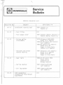
SERVICE BULLETIN LIST
BULLETIN NO.
SUBJECT
APPLICABLE TO
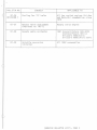
81-11
Crankshaft locking tool
1981 Everest LC
Futura LC
81 - 12
- Fuel filter
A11
- Fuel gauge cover
1981 Everest 500/E, Everest LC
Futura 500/E, Futura LC
- Driven pulley
disassembly
1979 Blizzard 5500-9500
Grand Prix Special
1980-81 Blizzard and Everest
(all models)
1980 - 81 Grand Prix Special
Grand Prix MX
Super & Ultra Sonic
Futura (all models)
- Throttle and brake
handle housing
1981 Blizzard (all models)
Grand Prix Special
Grand Prix MX
Super & Ultra Sonic
- Gear ratio
1980 - 81 Blizzard 9500
Ultra Sonic
Citation SS
Mirage Special
- Spring coupler
1981 Citation/Mirage
(all models)
- Ski leg washer
1980 Citation/Mirage
(all models)
1981 Bombardier
Snowmobiles Shop Manual
Supplement
All
81 - 1 3
81-14
81 -1 5
BULLETIN NO.
c~
SUBJECT
81-16
Brake light switch
1981 Blizzard (all models)
Grand Prix Special & MX
Super & Ultra Sonic
81-17
- Drive & driven pulley
removal
- Fuel tank air vent
1981 Blizzard (all models)
Grand Prix Special & MX
Super & Ultra Sonic
Everest (all models)
Futura (all models)
- Suspension cross shaft
screws
All units equipped with slide
suspension
81-18
Emergency cut-off switch
1abe 1
All 1981 models equipped with
lever type emergency cut-off
switch
81-19
Headlamp replacement bulb
Al 1 l 981 model s
Except Elan, Spirit & Nordik
81 - 20
Fuel line routing
All 1981 models
81-21
Suspension spring cross
reference chart
1981 Everest 500-500E
Futura 500-500E
Everest & Futura LC
Blizzard 5500,7500,9500
Grand Prix Special
Super & Ultra Sonic
81-22
Bushing replacement
procedure
1981 Blizzard MX
Grand Prix MX
81-23
Alternative spark plug
1981 Citation 3500, 4500,4500E
Citation SS
Mirage I, II, IIE, Special
Nordik
Everest 500, 500E, LC
Futura 500, 500E, LC
Blizzard 5500, MX
Grand Prix Special
Grand Prix MX
Elite
Engine storage protection
A11
Mikuni carburetor float
level adjustment
All
REVISION 1
81-24
REMINDER
cl
APPLICABLE TO
81-25
'------------~---------------------------J--------------------------------~
f<:I:"D\/Trt:"
Rill I I="TTN
I TST).
PAGE 2
•
•
~
II
BULLETIN NO.
81-26
REVISION 1
SUBJEC T
APPLICABLE TO
Cooling fan "V" belts
A11 fan cooled engines Ski-Doo
and Moto -S ki snowmobiles since
1975
81 - 27
Rotary valve adjustment
(Replaces no. 80-7)
Rotary valve engine
81-28
Speedo cable protector
1 981 Everest/Futura 500-500E
Everest/Futura 464 LC
Blizzard 5500/Sonic
Blizzard 9500/Ultra Sonic
81 - 29
Volatile corrosion
inhibitor
All 1982 snowmobiles
(SERVICE BULLETIN LIST), PAGE 3
Service
Bulletin
c
Date: May
14 ,
Serial nos:
ALL
1982
MODELS:
no.s2- 12
ALL
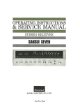
Subject: B u ~ c h / N • G • K •
Spa r k
P lug
Conversion Chart
This conversion chart has been established for the 1980 , 1981 and
198 2 snowmobiles models .
For the older models, this chart can be
used as a g uide .
The spark plug carbon ana l ysis remains the best
way to properly identify the right heat range .
, . , CAUTION : Severe engine damag e can occur if a wrong
~ heat range plug is u s ed :
A too "ho t" plug will result in overheating and reho t poi n ts pre-ign i tion , etc .
c
A too "cold" plug will r e su lt in fouling (shorting
t h e spark) or may create carbon build up which can
heat up r ed-ho t and cause pre-ignition or detonation.
c
All rights reserved ,c, Bombardier Inc.
*Trademarks of Bombardier Inc.
Litho'dinCanada
<t)
(BOMBARDIER SNOWMOBILES, SERVIC E 82 -1 2), PAGE 1
CONVERSION CHAR:
!2l
BOSCH
N.G . K.
:J>
!2l
Spark Plug
Identification
Bombardier
Part Number
Spark Pl ug
I dentification
Bombardier
Part Number
0
c+
M 175Tl
420 999 841
420 999 141
A-6
N.A.
A-7
284 001 027
420 999 881
420 899 731
A-7
A-8
284 001 027
284 001 028
420 999 230
A-8
284 001 028
420 999 190
420 89 7 010
B7HS
284 001 050
2 81~ 001 050
420 899 121
420 899 120
B7HS
420 899 180
420 899 181
B8HS
420 897 020
420 899 890
B9HS
420 899 940
BR7ES
Jn4 478 800
284 001 034
284 001 048
W 260 MZ 2
420 899 721
37ES
B8ES
w 275'12
4 20 899 920
BR8ES
w 280MZ2
420 899 570
B8ES
414 482 900
28h 001 051
W 300T2
420 899 576
B9ES
234 001 054
B9EV
284 001 055
284 001 058
{lJ
'0
'0
I-'
,.....,
0:1
0
!3:
0:1
!J>
:;o
t:l
H
.....
M 225T1
M 2 40Tl
()
{lJ
o'
I-'
(D
M 260Tl
M
2 80T31
w 225Tl
t:Q
:;o
W 250T l
(/)
W 240MZ 1
z
0
~
!3:
0
t:x:t
H
t""'
trJ
(/)
(/)
t:Q
:;:d
<;
w 240Tl
W 260T1
vl 260MZ1
\·1
275T1
W 280MZ1
'vl
2 50T2
B7HS
B71IS
B8HS
B9HS
H
(')
trJ
CXl
N
I
1-'
N
'-"
'1:1
:>
CJ
t'1
N
w 340S2S
420 899 476
BlOEV
28lf 001 050
28lf 001 0 50
2 84 001 053
284 001 053
284 001 056
2 8lt 001 056
4111 482 900
284 001 051
4 14 lq8 900
284 001 036
Service
Bulletin
0
1982
SERVICE BULLETIN LIST
BULLETIN NO.
SUBJECT
APPLICABLE TO
82 - 1
Armature plate replacement
part
1982
82 - 2
N.G.K. spark plug replacement part
1979-80 - 81 Vehicles equipped
with 277, 3 7 7' 464 and
503 engine types
82 - 3
Engine retaining bracket
ass'y
1980
Blizzard 7500/9500
Blizzard 7500/9500 Eur.
Super & Ultra Sonic
1981
Blizzard 7500/9500
Super & Ultra Sonic
1982
Citation 3500/4500E/SS
Mirage I/IIE/ Special
Nordik, Skandic,
Futura 300 & LC
Blizzard 9500
Everest LC
Ultra Sonic
(_
82-4
- 1982 Engine
& vehicle
technical data posters
and binder sizes
corrections
-
c
1982 Operator's manual
specification section
correction
Blizzard 5500 MX/9500
Sonic & Ultra Sonic
82-5
Removal of Skandic hood
grills
1982
Skandic
82 - 6
Battery installation
1982
Elite
82-7
Hitch bracket reinforcement tip
1982
Nordik/Nordik Europe
Skandic
82-8
Carburetors adjustment
1982
Blizzard 9500
Ultra Sonic
82-9
Information on high
altitude and/or deep snow
cal i b rations
1982
All s nowmobiles
(SERVICE BULLETIN LIST), PAGE 1
BULLETIN NO.
82-10
82-11
SUB.JECT
APP LICABLE TO
Vehicle storage procedure
(engine and pr i mer valve)
All
1981 Red and blue pilot
1981
Everest & Elite
lamps
82-12
Bosch/N . G.K. spark plug
conversion chart
All
(SERVICE BULLETIN LI ST ), PAGE 2
Service
Bulletin
Date: 1981
month
dav
05
26
no. 81-29
MODELS: ALL 1982 SNOWMOBILES
Serial nos: All
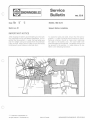
Subject Voltatile Corrosion Inhibitor
A ll the 1982 vehicles are protected against rust during
shipment by a new product called "Volatile Corrosion
Inhibitor".
It is necessary to remove and disca rd this capsule at predelivery.
The capsule locations for the different models are as follows :
- Elan - Spirit
!On the cylinder cowl - exhaust side)
c
- Citation 3500 - Mirage I
Citation 4500 - Mirage 11/E
Citation SS - M irage Special
Nordik - Skandic
(On the cylinder cowl)
- Everest 500/E - Futura 500/E
Blizzard 5500 MX - Sonic
!On the cylinder cowl near the forced flow tube)
- Everest LC - Futura LC
!On top of the magneto housing, side to rewind starter).
- Elite
!On the oil injection tank between the engine and the
exhaust pipe)
- Alpine
!On the fan housing - exhaust side)
Please send your comments on the efficiency of this
new product to your distributor.
c
All rights reserved © Bombardier Inc.
® *Trademarks of Bombardier Inc.
Litho' d in Canada
(BOMBARDIER SNOWMOBILES, SERVICE 81 -291
Service
Bulletin
c
no. 82-1
•l·•v
Date: 1981
05
08
MODELS: 1982 BLIZZARD 5500 MX
BLIZZARD 9500
1982 SONIC
ULTRA SONIC
Serial nos: All
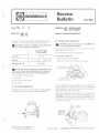
Subject Armature plate replacement part
The wires of the replacement part armature plote
assembly (PIN 420 866 650) for above listed models will
be longer than on the original part on the vehicle.
When installing th1s replacement part, secure the w111ng
using a tie wrap, as illustrated .
c
This w ill avoid loose wires from touching moving or
rotating parts .
c
~ *Trademarks of Bombardier Inc.
A ll rights reserved
(c>
Bombardier Inc.
Litho' d in Canada
(B OM BARDIER SNOWMOBI LES, SERVICE 82-1)
Service
Bulletin
c
no.
82-2
month
Date: 1981
06
MODELS: 1979, 1980 AND 1981 VEHICLES
EQUIPPED WITH 277,377,484 AND
503 ENGINE TYPES
Subject N.G.K. Spark plug replacement part
Serial nos: All
The 1982 vehicles usinq 277. 377. 464 and 503 enqi ne
types will be equipped with N. G. K. spark plugs.
It is possible to install the N. G. K. spark plugs to the
same engine types previously used on 1979, 1980 and
1981 vehicles. If the standard Bosch W 250 T 2 IW 4 Cl
- {P /N 420 899 940! needs to be replaced, you can use
the new N.G .K. BR -7ES spark plug {P/N 414 4788 OOl .
If the standard Bosch W 275 T 2 (W 3 Cl - IP /N 420 899
920) needs to be replaced, you can use the new N. G. K.
BR-8ES spark plug (P/N 414 4787 00!.
The N.G.K . spark plug numbering system is as follows:
c
BA-SES
Threads diameter
(14 mm)
Super wide ra nge
electrode
Threads leng th
Reststor type
Hea t range
0
NOTE: A N.G.K . BR-8ES is colder than a N.G.K.
BR-7ES.
c
® *Trademarks of Bombardier Inc.
All rights reserved © Bombardier Inc.
Litho' d in Canada
(BOMBARDIER SNOWMOBILES, SERVICE 82-2)
c
Service
Bulletin
Yea'
Date: 1982
month
day
04
28
no. 82-3
(REVISION 1)
MODELS: 1980 BLIZZARD 7600
BLIZZARD 7600 (EUR)
BLIZZARD 9&00
Serial nos: 3570, 3571, 3573, 3574
3577,3679,5313,5314
5316,5317
BLIZZARD 9600 (EUR)
SUPER SONIC
ULTRA SONIC
1981 BLIZZARD 7600
BLIZZARD 9600
SUPER SONIC
ULTRA SONIC
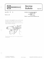
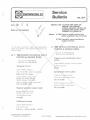
Subject Engine retaining bracket ass'y
The 1982 Blizzard 9500 & Ultra Sonic are equipped with
an engine retaining bracket ass'y . This feature wil l add
extra life to the drive belt by preventing the engine from
twisting upon acceleration.
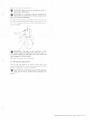
- Install the 90° brace end to the retainer plate and the
other end to the hook. Secure it using the two (2)
nuts.
"B"
In order to update our product, it is possible to install
this retaining bracket on the above listed vehicles using
the following pa rts:
c
-
1 Retainer plate
2 Screws
2 Lockwashers
1 Hook weldment
1 Brace
2 Nuts
P/N 512 035
P/N 222 082
P/N 224 781
PIN 512 035
P/N 512 035
P/N 396 302
200
065
140
300
400
400
Brace
INSTALLATION:
- Install the hook weldment to the engine support.
_ .....
~ 1l After pulley alignment. torque nut "B"
to 4-5 N•m 13-4 ft-lbsl.
2) Holding nut "B" torque nut "A"
to 20-27 N•m 115-20 ft-lbs) .
3) Reverify pulley alignment.
- Install the retainer plate to the engine crankcase electric starter location. Secure it using the two (2)
screws and lockwashers. Torque to 20-27 N•m (15-20
ft-lbs).
0
c
.
NOTE: Ensure the retainer plate brace hole is
located to its highest position.
Wlr CAUTION: Ensure that the crankcase halves are
'Y grooved the same as an electric engine type.
Wlr CAUTION: Before installation ensure that the
Y crankcase holes are threaded. If there are no
threads, the modification can not be performed.
0
NOTE: It is suggested to use the same installation
procedure for the 1982 Blizzard 9500 & Ultra Sonic.
Since this is a product improvement no wa rranty applies.
All rights reserved © Bombardier Inc.
® *Trademarks of Bombardier Inc.
.
Litho'd in Canada
(BOMBARDIER SNOWMOBILES, SERVICE 82-3)
Service
Bulletin
c
Date:
Year
mon1h
day
1981
06
23
Serial nos:
no. 82-3
MODELS: 1980 BLIZZARD 7500
BLIZZARD 7500 (EUR)
BLIZZARD 9500
BLIZZARD 9&00 (EUR)
SUPER SONIC
ULTRA SONIC
3570,3571,3573,3574
3577,3579,5313,5314
5316, 5317
1981 BLIZZARD 7500
BLIZZARD 9500
SUPER SONIC
ULTRA SONIC
Subject:
The 1982 Blizzard 9500 & Ultra Sonic w ill be equipped
with an engine retaining bracket ass'y. This feature w ill
add extra life to the drive belt by preventing the engine
from twisting upon accelera tion .
c
Engine retaining bracket ass'y
- Install the 90° brace end to the retainer plate and the
other end to the hook . Secure it using the two (2)
nu ts.
In order to update our product, it is possible to install
this retai ning bracket on the above listed vehicles using
the following parts:
-
1
2
2
1
1
2
Retainer plate
Screws
Lockwashers
Hook weldment
Brace
Nuts
P/ N
P/N
P/ N
P/ N
P/N
P/N
512
222
224
512
512
396
035
082
781
035
035
302
200
065
140
300
400
400
Brace
INSTALLATION:
- Install the hook weldment to the engine support.
- Install the retainer plate to the engine crankcase electric starter location . Secure it using the two (2)
screws and lockwashers. Torque to 20-27 N•m (15-20
ft-lbs)
0
1) After p ulley alignmen t, torque nut "A"
to 4-5 Nom 13-4 lt-lbsl
2l To rque nut "B" to 20-27 Nom (15-20 ft-lbsl.
31 Reverify pulley alignm ent.
NOTE: Ensure the retainer plate brace hole is
located to its highest position.
W
CAUTION: Ensure that the crankcase halves are
.,. grooved the same as an electric engine type.
W
CAUTION: Before installation ensure that the
.,. crankcase holes are threaded. If there are no
threads, the modification can not be performed.
c
All rights reserved © Bombardier Inc.
® *Trademarks of Bombardier Inc.
Since this is a product improvement no warran ty applies .
Litho'd in Canada
!BOMBARDIER SNOWMOBILES, SER VICE 82-3), PAGE 1
Service
Bulletin
monlh
Date: 1982
06
no.
82-4
(REVISION 1)
day
MODELS: 1982 CITATION 3500, 4500/E, SS
MIRAGE I, 11/E, SPECIAL
NORDIK, SKANDIC, FUTURA 300
BLIZZARD 9500, ULTRA SONIC
EVEREST UC, FUTURA UC
23
Serial nos: Not applicable
Subjets:
A) 1982 Engine & vehicle technical data
posters and binder sizes corrections
B) 1982 Operator's manual specification
section correction
For the above mentioned models, some specifications
MUST be corrected in their respective publications, proceed as follows:
c
+
A) 1. 1982 ENGINE TECHNICAL DATA
POSTER
- Ski-Doo {P/ N 484 0458 00)
- Moto-Ski {P/N 484 0460 00)
2. 1982 VEHICLE TECHNICAL DATA
POSTER & BINDER SIZES
- Ski-Doo {P /N 484 0457 00)
- Moto-Ski {P /N 484 0459 00)
Pressure lever identification (drive
pulley)
Citation 4500 & Mirage II (manual models):
A3SH should read:
Timing (B.T.D.C.)
B3KSH
Citation 3500 & Mirage I:
2.52 mm (0.099") indirect should read:
2.85 mm {0.112") indirect
Spring length (drive pulley)
Citation SS, Mirage Special:
Citation 4500/E, Citation SS,
Mirage 11/E, M irage Special,
Nordik, Skandic, Futura 300:
110.4 mm (4.346") should read:
100 mm {3.938")
2.52 mm (0.099") direct should read:
2.31 mm (0.090") direct
Nordik , Skandic, Fu tura 300:
96.5 mm {3.799") should read
Magneto generator output (watt)
100 mm (3.938")
Blizzard 9500, Ultra Sonic,
Everest L/C, Futura L/C:
160 w atts should read
140 watts
Crankshaft end-play
Citation 3500 & Mi rage 1:
N.A. should read:
0.20 mm - 0.40 mm (0.008" - 0.016")
All rights reserved
©
Bombardier Inc.
® *Trademarks of Bombardier Inc.
Litho' d in Canada
(BOMBARDIER SNOWMOBILES, SERVICE 82-4), PAGE 1
B)
1982 OPERATOR'S MANUAL
All C1ta t1on : (P/N 414 4467 OOJ
All Mirage: IP/N 414 4468 OOJ
Nordik, Skand1c: IP/N 41 4 4727 :JOl
Futura 300: IP/N 4 14 4810 OOl
Timing spec1flca tion must be changed to lhe
followmg:
Citation 3500
Mirage I
2.85 mm B.T. D.C.
(0. 11 2" ) 20°
C1tation 4500/ 1:
Mirage 11/E
Citation SS
Mirage Spec1al
Nordik, Skandic
!-=u tura 300
2.31 mrn B. I .D.C .
(0.090") 20°
(BOMBARDIER SNOWMOBILES, SERVICE 82-4), PAGE 2
Service
Bulletin
c
n um l ll
d'"IY
11
02
no. 82-4
MODELS: 1982 CITATION 3500, 4500/E,
MIRAGE I, lifE, SPECI
NORDIK, SKANDIC,
TURA 300
BLIZZARD 9500, U RA SONIC
EVEREST UC, F URA UC
ot applicable
Subjets:
A) 1982 Engine & veh· e technical data
posters an
inder sizes corrections
8) 1982 Operat
's manual specification
sect· n correction
HICLE TECHNICAL DATA
ER & BINDER SIZES
For the above mentioned models,
me specifications
MUST be corrected in their respective
ceed as follows:
c
A) 1. 1982 ENGINE TECHNICAL 0
POSTER & BINDER SIZES
- Ski-Doo (P /N 484 0458 OOl
- Moto-Ski (P/N 484 0460 OOJ
Ski-Doo !P/N 484 0457 OOl
- Moto-Ski (P/N 484 0459 OOl
Pressure lever identification (drive
pulley)
Citation 4500 & Mirage II (manual models):
A3SH should read
Timing (B.T.D.C.)
B
SH
Citation 3500 & Mirage 1:
2.52 mm (0.099") indirect should
ad:
2.85 mm (0.112") indirect
Citation SS ,
Citation 4500/E, Citation S ,
Mirage 11/E, Mirage Spec· ,
Nordik, Skandic, Futur 00:
· age Special :
11 0.4 mm (4.346'
hould read :
100 mm (3.938")
2.52 mm (0.099") dir t should read :
2.31 mm (0.090") d' ect
Nordik, Skandic, Futura 300:
96.5 mm (3.799") shouid read :
100 mm (3.938")
Blizzard 9500 Ultra Sonic,
Everest L/ , Futura L/C :
Cr
c
kshaft end-play
Citation 3500 & Mirage I:
N .A. should read :
0.20 mm - 0.40 mm (0.008" - 0.016")
All rights reserved © Bombardier Inc.
® *Trademarks of Bombardier Inc.
Litho' d in Canada
(BOMBARDIER SNOWMOBILES, SERVICE 82-4), PAGE 1
c
8)
1982 OPERATOR'S MANUAL
All Citation: (P/N 414 4467 OOl
II Mirage (P/N 414 4468 OQ)
rdik, Skandic: (P/N 414 4727 00)
Fut a 300: (P/N 414 4810 00)
Timing pecification must be changed to the
followin ·
Mirage I
2.85 mm B.T.O.C.
(0.112") 20°
Citation 4500/E
Mirage 11/E
Citation SS
Mirage Special
Nordik, Skandic
Futura 300
c
I
c
tn,....••r-.
A,..,...,~,...""'
.. ,,.... •• , •• ,.._.,_ ....
,.... _ _,, ...... - -- ··
- · -
c
Service
Bulletin
OIOnth
dnv
10
05
Date: 1981
no.
82-5
MODEL: 1982 SKANDIC
Serial no: 3179
Subject Removal of Skandic hood grills
The 1982 Skandic has been equipped with snow deflector grills on the hood to prevent snow from entering the
ennine compartment. However, under certain warmer
tempera tures, springtime as an example, these grills
may be removed. This will enable the engine to ru n
cooler.
REMOVAL PROCEDURE
Using a small Philips screwdriver, remove the four
screws holding the upper grill (PIN 517 1477 00) in posi tion.
Remove the grill .
c
] (l
II" lJ !lllOV('(j
Remove the four clips holding the two lower grills (P /N
517 1478 OOl m position .
Remove the grills.
NOTE: If you nrc in an area of continual deep fluffy
snow conditions, we suggest the grills not be removed.
0
Since this is a product improvement, no warranty ap
plies.
All rights reserved <!') Bombardier lnc.
® *Trademarks of Bombardier Inc.
Litho'd in Canada
(BOMBARDIER SNOWMOBILES, SERVICE 82-5}
Service
Bulletin
c
YCJI
monlh
dew
10
13
Date: 1981
no. 82-6
MODEL: 1982 ELITE
Serial nos: All
Subject Battery installation
IMPORTANT NOTICE
After charging the battery and reinstalling it on the vehicle, particularly during pre-delivery operations, it is important that the positive ( +) cable, the fuse holder w ire
and the taillight w iring be isolated from the alternator
pulley and belt. Wiring and/or cable contact with these
rotating parts could cause an electrical short .
To isolate the wires and cable, ensure that the battery
positive ( + l cable is directed down toward the frame.
Particular attention should be made when tightening
the cable to the battery post. The fuse holder wire
should be taped to the harness . The taillight wiring must
be secured to the positive ( +) cable using a tie rap
Refer to the following illustration.
Harness
c
® *Trademarks of Bombardier Inc.
All rights reserved <<;> Bombardier Inc.
Litho'd in Canada
I BOMBARDIER SNOWMOBILES, SERVICE 82-6!
Service
Bulletin
0
Date:
1981
rnnnl!
d ......
11
10
no.
82-7
MODELS: 1982 NORDIK
NORDIK (EUROPE)
SKANDIC
Serial nos: 3177, 3178, 3179
Subject
Under heavy load pulling conditions over rough terrain,
thme is a possibility that the trailer hitch bend . It is sugqP.sted that on machines used in these conditions two
bolts bolts be installed to lock the hitch securely to the
h11mper.
Following the measurements as per illustration :
Hitch bracket reinforcement tio
- Center punch the hitch plate
- Make the holes using a 7.0 mm (9/32") drill .
- Install the screws, washers and nuts then tighten
leaving 3-4 threads protrude through the nuts.
PARTS REQUIRED:
- 2 Screws P/N 222 064 565
- 2 Washers PI N 224 061 201
fi
I•
:
- 2 Nuts P/N 228 761 045
c
75.0 mm
1295")
L
PROCEDURE:
:
-~~
f 10mm
II
(0.393")
':
:
J'II
I
I
~
"-. Holes 7.0 mm
)
(9t32")
-0( ~~~3~3r;\
33 rnm l -.r
11 ·29 ")
- Remove hair pin from the hitch .
250.0 mm
!9.84")
- (Skandic models) as illustrated,
95.00 mm
_,l
(3.74")
I
Fla t washer
crew
Bumper
Remove the eight (8) nuts and screws securing the
rack to the frame.
- Unplug the tail lamp wiring terminals.
=- 3 4 Threads protrudmg
- Remove the rack.
m
(1.29")
- To install, reverse removal procedure.
-CAUTION: To prevent paint and/or decal dam'Y age, care must be taken at removal/installation of
the rack.
-CAUTION: To prevent damage to bumper grip,
'Y attention must be taken while drilling the bottom
part of the hitch plate.
This is a suggestion for product improvement .
ISkand1k models)
No warranty applies.
c
All rights reserved © Bombardier Inc.
® * Trademarks of Bombardier Inc.
Litho' d in Canada
(BOMBARDIER SNOWMOBILES, SERVICE 82-7), PAGE 1
Service
Bulletin
Date: 1981
11
13
no. 82-8
MODELS: 1982 - BLIZZARD 9500
1982- ULTRA SONIC
Serial nos: 3587 - All
5322- All
Subject: Carburetors adjustment
To adjust the carburetors when performing pre-delivery
operation or vehicle servicing, proceed as follows.
B) Throttle slide adjustment
W
CAUTION: Check oil injection pump adjustment
- , each time carburetor is adjusted.
BLIZZARD 9500
ULTRA SONIC
Air screw
WARNING: Ensure the engine is turned OFF, prior
to the throttle slide adjustment.
•
For maximum performance, correct carbu retor throttle
slide adjustment is critical.
The following method should be used
With engine turned off:
1.5 turn
- Remove the air in take silencer.
Main jet
P T 0 • 310
Idle speed R.P.M.
MAG . • 330
- Back off the idle speed screws completely.
1800-2000
W
CAUTION: Never operate the snowmobile with
. . the air intake silencer disconnected. Serious engine damage will occur if this notice is disregarded.
Cable adJUSter
lone each carbure tor). _
c_.
The carburetor ad justment are•
A) Air screw
Bl Throttle slide adjl!stment
Cl Idle speed
A) Air screw adjustment
Completely close the air screw (until a slight reseating
resistance is felt) then back off screw as specified .
Turn the idle speed screw clockwise until it con tacts the
throttle slide then continue turning two (2) additional
turns. Repeat on the other carburetor. This w ill ensure
identical throttle slide idle setting .
With the throttle cable adjuster jam nuts unlocked, fully
DEPRESS the throttle lever and check to have the throttle FLUSH with the top of the carburetor OUTLET bore.
To adjust, turn the carburetor cable adjuster, clockwise
or counter-clockwise.
,.
ri .,.__
~
Cable
adJustor
Throttle slide
FLUSH w ith
the top of the
OUTLET bore
c
All rights reserved t{:.J Bombardier Inc.
(!>)
* Tradema rks of Bombardier Inc.
Litho' d in Canada
!BOMBARDIER SNOWMOBILES, SERVICE 82-8), PAGE 1
llnp<::'ll lnr ihR other carb<netor.
W
CAUTION : Make sure both carburetors start to
... operate simultaneously .
WARNING : It is important that the throttle slide
•
adjustment be performed to ensure proper functioning of throttle mechanism.
Once both carburetors are adjusted, c.heck thnl w11h thf
throttle lever llllly depn~sserl, thP.re IS il fret: pinY of 1 b
mm (I It/') between the cover <md throttle slide Rr!Ad
111~1 nccordtngly.
xt=-l
IA;-:;:,:,\, ',~,\~l;§r ll
,l1 M~
y·:.
\
j ).~)
.(r~ I
-
,,~t;--
~~
r
""1
~
WARNING: This gap is very important. If the
•
throttle slide rests against the carburetor cover at
full throttle opening, it will create too much strain and
may damage the throttle cable.
Rec::heck carburetor synchrunization
C) Idle speed adjustment
Start engine and allow it to warm up then adjust idle
speed to 1800 2000 R. P.M. by turning tdle speed screws
equally clockwise or counter clockwrse.
CAUTION: Do not attempt to set the idle speed by
. , using the air screw. Severe engine damage can
occur.
( BOMBARDIER SNOWMOBILES. SERVICE 82-8). PAGE 2
Service
Bulletin
no. 82-9
l llOrlt lr
Date: 1982
01
MODELS: ALL 1982 SNOWMOBILES
22
Serial nos: All
Subject Information on high altitude
and/or deep snow calibrations
This bulletin is published as a guide to help you calibrate
the snowmobiles wich are operating in high altitude
areas. It summarizes the instruction sheet charts used in
the 1982's high altitude kits . Adjustment varies w ith
temperature, altitude and snow conditions.
NOTE: Even at sea level, under certain deep snow
conditions, some of these modifications in the drive
pulley, driven pulley and gear ratio could be performed to
obtain better performance.
0
c
c
All rights reserved © Bombardier Inc.
® *Trademarks of Bombardier Inc.
Litho'd in Canada
{BOMBARDIER SNOWMOBILES, SER VICE 82-9), PAGE 1
MODIFICATIONS & AD "'.J STMENTS CHART
(HIGH ALTil UDE KIT)
DRIVE PULLEY
MODEL 1982
Elan
Spirit
Kit PIN 861 7106 00
Citation 3500
Mirage I
Kit PIN 861 7133 00
RELEASE
SPRING
CENTRIFUGAL
LEVER KIT
TENSION
ADJUSTMENT
llbsl
CARBURATION
GEARING
DRIVEN PUllEY
TOP SPROCKET
lleethl
LOWER SPROCKET
lteethl
CHAIN
lhnksl
NEEDLE CIRCLIP
POSITION
FRON TOP
AIR SCREW
llurm
3'
1.5
2'
2.0
2'
1.5
2'
1.5
PILOT JET
NO
MAIN JET NO. IOTYI
2«0 m
18000 ttl
JOOOm
110000 ttl
150
404 1209 00
150
150
190
404 1190 00
180
404 1122 00
170
404 1238 00
240
404 1002 00
230
404 1189 00
220
404 11 12 00
1800 m
1600() ttl
Blue
414 2581 00
10
Yellow
12
414 4423 00
Citation 4500
Mirage II
Kit PIN 861 7134 00
Citation 4500 E
Mirage II E
Kit PIN 861 7134 00
12
14
504 0127 00
35
504 0129 00
14
504 0127 00
35
504 0129 00
14
504 0127 00
35
504 0129 00
35
404 1027 00
Nordik
Skandic
Kit P/N 061 7136 00
Citation SS
Mirage Special
Kit PIN 861 7135 00
to
0
3:
to
Everest 500/E
Futura 5001E
Kit PIN 861 7137 00
Remove 4 washers
lnsll!8 new rots 141
12
228 5810 45
2
m
::0
(J1
z
~
3:
0
to
r
Everest UC
Futura UC
Kit PIN 861 7140 00
125 12!
120 121
404 1248 00 121
404 1139 00 121
270
404 1004 00
260
404 1006 00
250
404 1003 00
300
404 1012 00
270
404 1004 00
250
404 1003 00
Yellow
14·15
414 1995 00
18
504 0437 00
2'
1.0
.
)>
:rJ
130 121
404 1249 00 121
Urange
14-15
38
504 0289 00
414 4065 00
Blizzard 5500 MX
Sonic
Kit PIN 861 7138 00
66
412 1042 00
3'
1.5
3'
2.0
30
404 1077 00
2 kits
14·15
860 4132 00
18
504 0437 00
200 121
195 1?1
190 1?1
404 1123 00 121
404 1194 00 121
404 1190 121
240 PTO
220 PTO
404 1091 00 121
260 MAG
404 1006 00
240 MAG
404 1002 00
200 PTO
404 1123 00
220 MAG
404 11 12 00
25
404 1103 00
240
404 1002 00
220
404 1112 00
210
404 1191 00
2400 m
18000 hi
3000 m
110000 hl
m
(J1
(J1
m
::0
~
(}
m
R3
{e
-o
Blizzard 9500
Ultra Sonic
Kit PIN 861 7139 00
Black
3 kits
414 4784 00
860 4173 00
Alpine
Kit PIN 861 7109 00
Light blue
414 1967 00
)>
(;)
14·15
19
504 0438 00
3'
15
2•
ABOVE 1800 METERS 16000 feet!
m
N
u
u
1.5
1.5
40 121
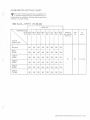
CARBURETOR SETTING CHART
-CAUTION: These adjustments are guidelines on•
ly. Specific adjustments vary with temperature, altitude and snow conditions. Always observe spark plug
condition for proper jetting .
1982 ELAN - SPIRIT VM 28-242
MAIN JET
TEMPERATURE
(DoC) -50°C -40°C -30°C -20°C -5°C
(0oF) (-60) (-40) (-20)
(0)
(20)
5°C
(40)
15°C 25°C
(60)
(80)
Needle E
clip position
from top
Pilot
jet
Air
screw
30
30
1 112 turn
Altitude
Meters (feet)
0
Sea level
160
160
160
160
160
160
160
160
600 m
(2,000)
160
160
160
160
160
160
160
160
1,200 m
(4,000)
160
160
160
160
160
160
160
160
1,800 m
(6,000)
150
150
150
150
150
150
150
150
2,400 m
(8,000)
150
150
150
150
150
150
150
150
3,000 m
(10,000)
150
150
150
150
150
150
150
150
{BOMBARDIER SNOWMOBILES, SERVICE 82-9), PAGE 3
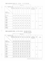
1982 CITATION 3500 - MJRAG E I VM 34-255
MAIN JET
TEMPERATURE
(OOC) -sooc -40oC -30°C -20° C -S°C
(20)
(0°F) (-60) (-40) (-20) (0)
S°C
(40)
15°C 2S°C
(60) (80)
Needle E
clip position
from top
Pilot
jet
Air
screw
30
30
1 112 turn
20
3S
2 turns
Altitude
Meters (feet)
0
Sea level
240
240
230
220
210
200
19S
18S
600 m
(2,000)
230
230
220
210
200
190
18S
17S
1,200 m
(4,000)
220
210
210
200
190
180
170
16S
1,800 m
(6,000)
210
200
19S
190
185
180
17S
170
2,400 m
(8,000)
19S
190
18S
180
175
170
16S
160
3,000 m
(10,000)
185
180
175
170
16S
160
155
150
tBOMBARDIEA SNOWMOBILES, SERVICE 82-9), PAGE 4
1982 CITATION 4500/E- MIRAGE 11/E
NORDIK, SKANDIC VM 34-276
MAIN JET
TEMPERATURE
(OoC) -50°C -40°C -30°C -20°C -S°C
(OOF) (-60) (-40) (-20)
(0)
(20)
soc
(40)
15°C 25°C
(60)
(80)
Needle E
dip position
from top
Pilot
jet
Air
screw
Altitude
Meters (feet)
0
Sea level
290
280
270
260
250
240
230
220
600 m
(2,000)
290
280
270
260
250
240
230
220
1,200 m
(4,000)
280
270
260
250
240
230
220
210
30
35
1,800 m
(6,000)
270
260
250
240
230
220
210
200
2,400 m
(8,000)
260
250
240
230
220
210
200
190
3,000 m
(10,000)
250
240
230
220
210
200
190
180
1 112 turn
20
1982 CITATION SS-MIRAGE SPECIAL 2X VM 34-277
MAIN JET
TEMPERATURE
(OoC)
(OoF)
-sooc
(-60)
-40°C -30° C -20°C -5°C
(-40) (-20)
(0)
(20)
soc
(40)
1S°C 25°C
(60)
(80)
Needle E
clip position
from top
Pilot
jet
Air
screw
40
1 112 turn
Altitude
Meters (feet)
0
Sea level
17S
170
165
160
15S
1SO
145
140
600 m
(2,000)
165
160
155
150
14S
140
13S
130
1,200 m
(4,000)
155
150
145
140
135
130
125
120
1,800 m
(6,000)
145
140
135
130
125
120
115
110
2,400 m
(8,000)
140
135
130
125
120
115
110
105
3,000 m
(10,000)
135
130
125
120
115
110
105
100
30
20
(BOMBARDIER SNOWMOBILES, SERVICE 82-9), PAGE 5
1982 EVEREST 500/E- FUTURA 500/E VM 36-114
I
MAIN JET
""' '
I
TEMPERATURE
(QOC) -50°C -40°C -30°C -20°C -5°C
(-60) (-40) (-20) (0)
(20)
"
w•FJ
I Altitude
'~
I
Meters (feet)
0
Sea level
5°C
(40)
15°C 25°C
(60) (80)
330
320
310
300
290
280
270
260
320
310
300
290
280
270
260
250
310
300
290
280
270
260
250
240
(6,000)
300
290
280
270
260
250
240
230
2,400 m
(8,000)
290
280
270
260
250
240
230
220
3,000 m
(10,000)
280
270
260
250 1240
230
220
210
600 m
(2.000)
l
I
jet
Air
screw
30
35
1 1/2 turn
20
30
1 turn
Pilot
jet
Arr
screw
40
1 112 turn
Neer.le E
cho position
from top
Pilot
1,200 m
(4,000)
1,800 m
i
1982 EVEREST L.C.-FUTURA L.C.
VM-227
MAIN JET
TEMPERATURE
(OoC) -sooc -40°C -30°C -20°C -5°C
(0oF) (-60) (-40) (-20) (0)
(20)
5°C
(40)
Needle E
15°C 25°C
(60) (80) clip position
from top
Altitude
Meters (feet)
0
Sea level
420
410
390
380
370
350
340
320
600 m
(2,000)
400
390
370
360
350
330
320
300
1,200 m
(4,000)
370
360
340
330
310
300
290
270
1,800 m
(6,000)
340
330
310
300
280
270
260
240
2,400 m
(8,000)
310
300
280
270
260
240
230
220
3,000 m
(10,000)
290
280
260
250
230
210
200
190
30
(BOMBARDIER SNOWMOBILES. SERVICE 82-9) PAGE 6
1982 BLIZZARD 5500 MX-SONIC
2X VM 34-203
I
MAIN JET
I
TEMPERATURE
(OoC) -50°C -40°C 30°C -20°C -5°C
(0oF) (-60) (-40) (-201 (0)
(20)
5"C
(40)
l5°C 25°C
(60)
1801
Altitude
Meters (feet)
240
240
230
220
210
200
195
185
600 m
(2,000)
240
240
230
220
210
200
195
185
240
230
220
210
200
195
190
185
-
Pilot
A1r
jet
screw
l
1
I ~ea level
1,200 m
(4,000)
Needle E
clip position
from •on
- -·
-
I 112 turn
3n
35
1,800 m
(6,000)
230
220
210
200
195
190
185
180
2,400 m
(8,000)
220
210
200
195
190
185
180
175
3,000 m
(10,000)
210
200
195 1 190 1185
180
175
170
-
2 turns
1982 BLIZZARD 9500 - ULTRA SONIC VM 36-118 PTO
VM 36-119 MAG
MAIN JET
TEMPERATURE
(ODC) -sooc -40oC -30°C -20°C -5°C
(20)
(0°F) (-60) (-40) (-20) (0)
Altitude
Meters (feet)
5°C
(40)
15°C 25°C
(60) (80)
Needle E
clip position
from top
Pilot
jet
Air
screw
PTO PTO PTO PTO PTO PTO PTO PTO
MAG MAG MAG MAG MAG MAG MAG MAG
330
350
0
340
Sea level
360
600m
320
(2,000)
340
310
330
1,200 m
(4,000)
300
320
290
310
1,800 m
(6,000)
270
290
2,400 m
(8,000)
3,000 m
(10,000)
320
310
330
300
320
290
310
280
300
270
290
260
280
250
270
240
260
300
290 270
310 ' 290
270 I 260
290 280
240
260
230
250
260
280
250
270
240
260
230
250
220
240
210
230
200
220
240
260
230
250
220
240
220
240
210
230
200
220
190
210
180
200
230
250
220
240
210
230
200
220
180
210
180
200
170
190
160
180
340
1
!
I
I
300
320
280
1
220
240
45
30
1 112 turn
40
--
(BOMBARDIER SNOWMOBILES, SERVICE 82 91, PAGE 7
1982 ALPINE
VM 34-215
MAIN JET
TEMPERATURE
(ODC) -50°C -40oC -30°C -20°C -5°C
(0oF) (-60) (-40) (-20) (0)
(20)
5°C
(40)
15°C 25°C
(60) (80)
Needle E
clip position
Pilot
iet
Air
screw
from top
Altitude
Meters (feet)
0
Sea level
310
300
290
280
270
260
250
240
600 m
(2,000)
300
290
280
270
260
250
240
230
1,200 m
(4,000)
290
270
260
250
240
230
220
210
30
30
1 112 turn
1,800 m
(6,000)
270
260
250
240
230
220
210
195
2,400 m
(8,000)
250
240
230
220
210
200
190
180
3,000 m
(10,000)
240
230
220
210
195
185
175
165
20
25
(BOMBARDIER SNOWMOBILES, SERVICE 82 9). PAGE 8
Service
Bulletin
no. 82-10
mon1h
Date: 1982
02
12
MODELS: ALL
Serial nos: All
Subject Vehicle storage procedure
(Engine and primer valve)
This Service Bulletin supersedes Service Bulletin (81 -24)
and also the storage procedure (cylinder lubrication)
with the recommended storage oil ( P/N 413 9048 00) as
described in t he 1982 Operator's Manual. The other procedures concerning cooling system, track, slide suspension, ski, controls, chaincase, fuel tank, carburetor,
drive pulley, chassis and battery remain the same.
Primer valve
1. Disconnect the inlet primer hose from the primer
valve .
To perform the storage procedures (engine and primer
valve) proceed as follows:
Engine
1. Start the engine and allow it to run at idle speed until
the engine reaches its operational temperature.
2. Stop the engine, remove the air silencer box, start
the engine.
3. Using the concentrated Bombardier Snowmobile Oil,
squirt oil into the carburetor(s) throat until the engine
dies.
4. Remove the spark plug{s) and pour approximately 85 ml
{3 fl. oz. imp., 3 fl. oz. U.S.) of oil into the cylinder(s)
5. Crank the engine to allow the crankshaft to turn 2 to
3 revolutions.
6. Reinstall the spark plug(sl and the air intake silencer.
2. Hold the hose higher than the gas tank to prevent
gasoline draining.
3. Using an appropriate hose . connect one end of the
hose to the inlet of the primer valve and place the
other end in a concentrated Bombardier Snowmobile
Oil can.
4. Activate the primer in order to fill it w ith oil.
5. Reinstall the inlet primer hose to the primer va lve .
We highly recommend that you advise your customers
of this revised storage procedure.
We suggest to post this Service bulletin to the view of
your customers or to publish it to them.
c
® *Trademarks of Bombardier Inc.
All rights reserved © Bombardier Inc.
Litho' d in Canada
{BOMBARDIER SNOWMOBILES, SERVICE 82-101
Service
Bulletin
Date:
Ap r i 1 1 9 , 1 9 8 2
Serial nos:
MODELS: 1981
Su~ect:
ALL
no.
82 - 1
EVEREST & ELITE
1981 Red & Blue Pilot Lamps
The 1981 pilot lamps are no longer available :
P/N 410 6063 00 (blue)
P/N 110 6056 00 (red)
The 1982 pilot lamps wi l l
retrofit :
P/N 410 6066 00 (blue)
P/N 410 6065 00 (red)
NOTE : To install the 1982 p i lot lamps on the 1981 Everest and
El ite, a rubber grommet ( P /N 570 2766 00) must be used as the
lamps are smaller .
O
Therefore,
if ordered
1981 P/N 410 6063 00
(blue)
1981 P/N 110 6056 00
(red)
Wi ll receive
Must order
1-P/N 410 6066 00
(b lue)
1 - P/N 510 2766 00
(gro mmet)
no thi ng
1 - P/N 410 6065 00
(red)
1 - P/N 510 2 766 00
(grommet)
INSTALLATION
c
Install the rubber grommet(s) into the dash using a soap and
water solution (applied to the retaining lips) .
Install the pi l ot lamp(s ).
® *Trademarks of Bombardier Inc.
All rights reserved © Bombardier Inc.
(nrnADADT\T"t'D
Cl\lfH.TM{)DTT"t'C
C"t'OUTf't;'
Q') _ l
l
\