1
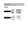
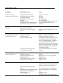
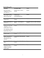
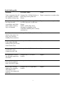
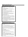
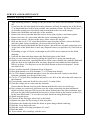
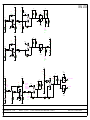
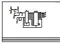
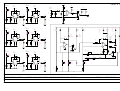
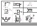
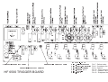
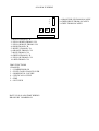
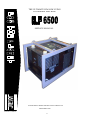
THE ULTIMATE JEM LOW LYING
FOG/SMOKE MACHINE
SERVICE MANUAL
PLEASE READ THESE INSTRUCTION CAREFULLY
JEM SMOKE PLC
Version 1.0 990127
0
HEAVY FOG 6500 SERVICE MANUAL
CONTENTS:
Index… … … … … … … … … … … … … … … … … … … … … … … … … … … … .Page 1
Features and Specifications… … … … … … … … … … … … … … … … … … … … … ...2
Safety… … … … … … … … … … … … … … … … … … … … … … … … … … … … … ... ..3
Safety and wiring off machine… … … … … … … … … .… … … … … … … … … … … ..4
Safety and wiring off machine… … … … … … … … … .… … … … … … … … … … … ..5
Fault Finding Guide… … … … … … … … … … … … … … … … … … … … … … … … … 6
7
8
9
Fault finding guide & 22 pin socapex guide … … … … ...… … … … ..… … … … … … 10
Service and maintenance. … … … … … … … … … … … … … … … … … … … … … … ..11
12
13
14
15
16
DMX 512 Option… … … … … … … … … … … … … … … … … … … … … … … … … … 17
Part number guide… … … … … … … … … … … … … … … … … … … … .… … … … … ..18
Heavy Fog 6500 mother wiring diagram… … … … … … … … … … … … … … … … ...19
Heavy Fog 6500 trigger wiring diagram… … … … … … … … … … … … … … … … … .20
Schematics… … … … … … … … … … … … … … … … … … … … … … … … … … … … ..21
1
Heavy Fog 6500 Features and Specifications:
The Heavy Fog 6500 is a dual purpose machine it can deliver Smoke or Low
lying fog at continuous output 24 hours a day 7 days a week 365 days of the
year. A series of vertical and horizontal louvers at the front of the machine
controlled by a jot-stick mounted on the controller will direct the low lying
fog wherever it is required, further more the controller has a pre-programmed
louver movement to reproduce scenic effects such as Sea, Wave, Cloud,
Waterfall, Curtain and volcano. The on-board 19" rack mounted controller can
be removed and mounted remotely or if preferred the machine can be
controlled via a lighting desk using either the 0-10v input connection through
a Mono Jack plug, and the 512 DMX card Via a 5 pin XLR plus a slave socket
to link the machines together.
Specifications:
Power requirements:
220v-240v 50hz 3 phase 20 amps per phase
208v 60hz 60 amp Single phase.
Heaters:
10kw
Fan speed:
0-3000rpm (1.2 amps)
Smoke output:
1250mc per minute
H.F output
500 square maters per minute
Pumps:
2 x Piston pumps (0.7amps each)
Fluid capacity:
2 x 5ltr integral tanks
Fluid types:
A1, B2,C3 and C4
Dimensions:
1170 x 760 x 715mm
Weight:
210kg
2
Safety
? ? Always connect to the correct mains power supply.
? ? Always use genuine JEM fog fluid.
? ? Always disconnect from the mains before attempting to start work on the
JEM H.F 6500.
? ? Do not suspend the machine above peoples heads.
? ? Do not stand directly at the front of the machine when firing.
? ? Do not block the airflow vent at the back of the machine.
? ? Clean the machines filters out once a month.
? ? Always install in a well-ventilated area.
? ? Ensure correct fluid is placed into specific smoke or heavy fog tanks.
? ? Never attempt to do any work on the machine if it isn't described in the
manual.
? ? Consult your supplier for advice on the JEM Heavy fog 6500.
3
Safety
Wiring of the machine
_
Because the machine, in most cases, will be wired to a 3 phase supply, a voltage of
415volts A.C will exist across each set of phases, therefore great care must be taken
when working on live apparatus.
ELECTRICITY KILLS. Under no circumstances should anyone without sound
electrical knowledge be permitted to work on this machine while connected to a live
electrical feed.
U.K AND EUROPEAN WIRING IF THE MACHINE
The U.K /European model operates on 220/240 volts and may be operated on a
single 220/240 volt phase, however, this causes a substantial current draw, so it is
much more desirable to use three separate phases to provide better load distribution.
The machine will benefit and run much more smoothly.
U.S.A WIRING IF THE MACHINE
The wiring connection is different in the U.S. In the U.S. 2 x 110volt phases (legs)
are used to obtain 208 volts, however the same cautions apply. To obtain a voltage
of 208 volts from two 110 volt legs, connect all live feeds (Hots) together on one
leg, and the neutral Blue wire on the other leg. This will give you 208 volts.
Note in this situation the supply neutral is not used. To those unfamiliar with use if
multiple electrical phases, known as "Legs" in the USA this action may seem
strange but is common in the commercial field and normal practice. As always make
sure that the earth (ground wire in the USA) is properly connected. NEVER operate
this machine without the earth/ground wire connected.
4
Safety
Wiring of the machine
_
N.B. THIS APPLIANCE MUST BE EARTHED!
Wiring of Plug
240V 3 PHASE
BROWN
BLACK
PHASE 1
PHASE 2
BLACK
PHASE 3
BLUE
NEUTRAL
GREEN/YELLOW
EARTH
208V SINGLE PHASE
5
BLACK
PHASE 1
BLUE
PHASE 2
GREEN/YELLOW
EARTH
Fault finding guide
Problem
Probable Cause
Cure
Heater, Fan and
compressor fail LED's on.
Condenser fan fuse blown.
Condenser fan motor faulty.
Fan blade jammed.
Insufficient air flow to the
machine.
Low gas charge.
Condenser coil air outlet blocked
or restricted at rear of machine.
Replace Fuse No7.
Replace.
Re-align.
Clear restriction.
Re-site machine.
Check for leaks, purge and re-charge.
Clear restriction and or re-site
machine.
Red LED on motherboard
flashing.
Overheat sensor circuit activated
faulty sensor on block.
O/S Triac or Opto on Trigger
board.
Replace sensor or sensors.
Phase down.
Contactor 1 faulty.
Faulty capacitor.
Pressure switch tripped.
Compressor internal thermal
overload trip activated.
Check mains supply voltage.
Repair or replace Contactor 1.
Replace compressor capacitor.
Reset and try again, if trip re-activates,
check filters are clean and machine
isn't in an enclosed space, reset and
run again, if trips again reset and
check machine for gas, when running
high pressure side 200psi low pressure
side 30 psi (5lb of R22 in machine) If
less check for leaks.
If O.K check compressor for faults.
Replace.
Freeze fan and solenoid
switch fail lights on.
Evaporator fan motor failure.
Jammed fan wheel.
Evaporator fan fuse blown.
Solenoid failure.
Evaporator coil sensor faulty.
Mag valve sensor faulty.
Replace motor.
Rectify.
Replace fuse No 8 on trigger PCB.
Replace coil.
Replace sensor.
Replace sensor.
Heavy fog smoke rising.
Evaporator fan speed to high.
Fan voltage on low speed should be 75
- 85 volts, check this on mother PCB.
Replace, then purge and recharge.
Heavy fog button pressed
but does not activate after
normal delay period.
Faulty thermostatic expansion
valve.
Restriction in refrigeration circuit.
Solenoid valve jammed open.
Drier blocked.
Lack of refrigerant.
6
Replace Triacs or Opto's No's 1,2 6
and 7
Check pipe work for ice build up at
any one point and clear by applying
heat.
Clear or replace.
Replace.
Check for leaks, seal vacuum purge
and recharge.
Fault finding guide
Timer malfunction.
Damp or faulty switch.
Erratic special effects.
Excess voltage drop in control Try different controller or use shorter
cable.
control cable.
Damp controller.
Faulty power supply.
Condenser fan runs at
full speed on switch-on.
Broken sensor.
Wire broken or disconnected
on mother PCB.
Replace red sensor on condenser coil
Repair or re-connect wire.
No heavy fog output/
or no smoke output
Tank empty.
Air leak in pump or fluid line.
Faulty pump.
Pump fuse blown.
Refill.
Locate and reseal.
Replace.
Replace fuse No's 5 and 6.
*Earlier models only*
Blocked change over valve.
Change over fuse blown.
Change over valve faulty.
Clean and test.
Replace fuse No 5.
Replace or modify to current spec,
using two separate pumps.
Repair or replace
Faulty switch or broken LED.
High current draw.
Repair or replace.
Refrigerant overcharge.
Tight compressor.
Compressor electrical
problem.
Discharge valve leak.
Internal compressor leak.
Purge and recharge.
Run in for a few hours.
Wiring problem, Check and correct.
Low current draw.
Low refrigerant charge.
Water in system.
Check for leaks and re-seal.
Purge, evacuate and re-gas.
Servo faulty, no servo
action at all.
Faulty servomotor or wiring.
Repair or replace.
Block heats up O.K but
no heating LED on
controller.
Socapex line 22 (Red) broken. Repair.
7
Re-seal.
Replace compressor.
Fault finding guide
Problem
Probable cause
Cure
Heat fan LED &
Compressor fan fail
LED lights on.
Socapex line21 (White)
Broken.
Repair.
Servo appears faulty.
Smoke blows low on
floor or to one side.
Socapex line 3
(Yellow/Blue)or 4
(Yellow/Red) broken.
Repair.
No variable smoke
output at all.
Worn or damaged slider
control.
Replace.
Smoke output stuck on
minimum.
Broken + volts supply to
slider.
Reconnect wires on slider ensuring
secure.
Machine cannot be
turned on or off using
"Standby" or "on "
buttons. Mains LED is
dim. Machine works by
pressing the heavy fog
button only to start.
Socapex line 5 (Green/Brown) Repair.
broken.
Machine stays in
standby mode.
Socapex line 7 (White/Red)
broken.
Repair.
Smoke LED will not
light and difficulty
selecting heavy fog
function.
Socapex line 8 (Red/Brown)
broken.
Repair.
Heavy fog LED will not
light .
Socapex line 9 (Red/Black)
broken.
Repair.
Machine will not switch
from Heavy fog to
smoke or vice versa,
machine is stuck in
smoke mode.
Socapex line 10 (Red/Blue)
broken.
Repair.
8
Fault finding guide
Problem
Probable cause
Cure
Front evaporator fan will Socapex line 11(Pink) broken or
not respond to demand
4066 chip next to pink wire
for smoke or heavy fog. blown.
Repair connection or replace chip.
No smoke or heavy fog
but front fan still
controllable with slider
when smoke or heavy
fog is in demand.
Socapex line 12 (Orange) broken Repair connection or replace chip.
or 4066 chip next to pink wire
blown.
NOTE:- 4066 chip can be
damaged by plugging in the
controller with the power already
switched on.
Standby, mains on,
Smoke only works. No
heavy fog. Stuck in
standby from switch on.
Socapex line 13 (Purple) broken.
Repair.
Machine will not go into Socapex line 15(Brown) broken.
ready mode although
heating LED goes of and
front nozzle is hot.
Repair.
No operation of solenoid Socapex line 16 (Black) broken.
switch fail Led or
compressor fail LED.
Repair.
No operation of freeze
fan fail and compressor
fail LED's.
Socapex line 17 (Yellow)
broken.
Repair.
Smoke delivered when
heavy fog is required,
heavy fog LED is light.
Socapex line 18 (Green) broken.
Repair.
Heavy fog LED only
lights up on controller,
total failure of all
controls, but compressor
starts up.
Socapex line 19 (Light Blue)
broken.
Repair.
9
Fault finding guide
Problem
Probable cause
Cure
Mains on LED only
lights up on controller.
Total failure of all
controls but pumps run.
Socapex line 20 (Dark Blue)
broken.
Repair.
Machine has failed but
Socapex line 6 (White/Blue)
there are no file lights on broken
controller.
Repair.
22 pin Socapex wiring table
Pin
1
2
3
4
5
6
7
8
9
10
11
12
13
14
15
16
17
18
19
20
21
22
Colour
ORANGE/BLUE
ORANGE/GREEN
YELLOW/BLUE
YELLOW/RED
GREEN /GROWN
WHITE/BLUE
WHITE/RED
RED/BROWN
RED/BLACK
RED/BLUE
PINK
ORANGE
PURPLE
GREY
BROWN
BLACK
YELLOW
GREEN
LT BLUE
BLUE
WHITE
RED
Function
DMX -VOLTS
DMX +VOLTS
VERTICAL LOUVER
HORIZONTAL LOUVER
CONTROLLER LED + VE
COMPRESSOR FAIL
CONTROLLER ON LED -VE
REFRIGERATION OFF LED
REFRIGERATION ON LED
SMOKE H/F SIGNAL
FREEZE FAN FAIL
PUMP SIGNAL
STANDBY/ON
DMX GROUND
READY SIGNAL
DEFROST VALVE SIGNAL
FREEZE FAN FAIL
PUMP CHANGEOVER
GROUND (GND)
+12VOLTS
HEAT FAN FAIL
HEATING SIGNAL
10
SERVICE AND MAINTENANCE
Internal view of the machine
Section 1 Internal view of machine
For an internal view of the machine you must:
1. Unscrew all 28 screws on the outside of the
machine. This includes the side panels.
2. Remove the two nylon caps and nuts on the
front cover and push the fluid tanks down into
the machine.
3. Line up the 2 ducting clips on the front cover
so they are flat and pull the lid forward. The
rear lid will slide off backwards. Ensure the
controller has had its joystick removed before
this is done.
Section 2 view off Electronics door
1. Looking towards the front from the rear of the
machine, on your left-hand side of the machine
you will see a filtered side panel.
2. Unscrew all 6 (six) screws from around the
edges and remove the panel.
3. There you will see a slide out electronics door,
pull towards you for a view of the electronics.
4. On the electronics door you will see a Mother
PCB a Trigger PCB and 2 Contactor.
Section 3 Replacing the Trigger PCB
After following section 2.
1. Remove all crimps on the board.
2. Unscrew the second Triac in from the left of
the board.
3. Unscrew all four (4) nylocs in the corners of
the board.
4. Pull out the molex connector.
5. Remove the board.
6. Reverse the procedure to replace the board.
N.B. Trigger board connections are as follows,
PRE MAY 1997 (JEM HEAVY FOG V1.0)
N, 15,1,2,3,4,5,6,7,8,9,0,11,12,13,14.
POST MAY 1997 (LVD_TRIG.PCB)
N, 15,1,2,3,4,5,7,6,8,9,10,11,12,13,14.
The above connections are from right to left.
11
SERVICE AND MAINTENANCE
Section 4 Replacing the Mother PCB
After following section 2.
7. Remove all wires on the board. Making note
of the connections.
8. Remove all four-(4) nyloc in the corners of
the board.
9. Pull the board forwards to reveal the back of
the board.
10. Remove all soldered wire connections on the
back of the motherboard by de-soldering them,
making a note of the connections.
11. Remove the board.
12. Replace with new board.
13. Reverse procedure to replace the board.
Section 5 Replacing a Contactor
After following section 2.
1. Remove all wires on the contactor you are
replacing, making note were they were
removed from.
2. Remove the two- (2) nuts and bolts holding the
contactor in place.
3. Remove the contactor.
4. Replace contactor and Reverse procedure.
Section 6 Replacing a condenser sensor
After following section 1 and removing only the
back panel.
1. Cut wires as close to the red condenser sensor
as possible.
2. Remove all silicone from around the old
sensor, and remove sensor.
3. Strip the existing Red wires back about 3mm,
ensuring the joints are staggered.
4. Place heat-shrink over the red wire
connections.
5. Solder new sensor to the existing red wires.
6. Pull heat-shrink over the connections and Heatshrink.
7. Place some Heat sink past on the copper outlet
pipe from the coil.
8. Place the new sensor on top of it and tiewrapp,
12
Ensuring you do not break the sensor
SERVICE AND MAINTENANCE
Section 7 Replacing a servo board
After following section 1 and only removing the
front cover.
1. The servo boxes are on either side of the
machine at the front.
2. Remove the four- (4) screws holding the servo
box in-place.
3. Disconnect the louver arm connector.
4. Pull the box towards you. This will give you a
view of the servo PCB inside the box.
5. Disconnect the wires.
6. Unscrew the four- (4) screws on the bottom of
the box that hold the servo PCB in-place.
7. Remove the PCB.
8. Replace with new PCB.
9. If the metal arm connections on the bottom of
the PCB are not attached to the new PCB then
disconnect the metal connections from the old
PCB and fix to the new PCB.
10. When connecting, line the pot up on the bottom
of the board so that it is at half way through a
turn. This will give a central point on the louver
when in fire mode.
11. Reverse procedure from No 7.
Section 8 Replacing the vapour fan
After following section 1 and removing the front
cover only.
1. Remove earth from the fan.
2. Cut up the heat-shrink until you can see were
the wires join; cut the wires at this point.
3. Remove all the heat-shrink from of the cable.
4. Remove all the silicone from around the vapor
fan.
5. Remove the two- (2) bolts holding the vapor
fan in-place.
6. Remove the vapor fan.
7. Replace with new vapor fan.
8. To the existing wires sleeve with new heatshrink.
9. Around the edge of the new vapor fan once inplace, seal with silicone sealant.
10. Join the wires together by soldering ensuring
there is heat-shrink over the brown and blue 13
wire joints
11. Heat-shrink the connections and replace the
SERVICE AND MAINTENANCE
Section 9 Replacing the block
After following section 1, taking off only the front cover make sure the machine is turned
off.
If you have the old style block the heating elements will only be coming out of the block
1" in length and there will be heat resistant wire attached to them. The new blocks have 7"
of elements coming out of the block and are attached to the wires with crimps.
1. Remove the fluid tanks on both sides of the machine.
2. Remove the two screws that hold the sensor access plate in-place, and remove plate.
3. Remove the four- (4) screws that hold the sensor retaining plate in-place.
4. Remove the sensors, (do not cut the wires, these sensors are fragile)
5. Drill out the six (6) 1/16" rivets that hold the vapor fan plate in place, (above the block)
and place plate on-top of machine, (do not cut the wires to the fan).
6. Remove the bracket that holds the block in-place, this will have an earth connection on it.
7. At the back of the block there is an 8-way dispersal cone try to pull this off, if no luck cut
it off.
8. Depending on type of block, cut through or pull off the wires connected to the block
elements.
9. Undo all the 4mm nuts that connect the fluid inlet pipes to the block.
10. Now you can remove the block by pulling the block in it's casing up towards you.
11. Replace with new block, ensuring that it has all the correct fittings on it and the fluid inlet
pipes are bent in the right direction, the 8way dispersal cone cannot be fitted until the
block is in place, You may have to cut the block shroud as shown in diagram 1 for the
new block to fit.
12. Once in-place bend all 8 elements down 90 degrees.
13. Place heat-shrink over all 8 elements (3" of 12.6mm heat-shrink).
14. Cut 2"0f 6.8mm heatshrink and place it over the wires that will connect to the block
elements, (pushing it to the top of the wires).
15. Cut 8 x 9" of glass fibre insulation and push it over all 8 of the wires that will connect to
the elements.
16. If not already connected fit all the wires with 2.5 crimps (blue).
17. Push the crimps one at a time onto the elements.
Ensure that the Brown wires are at the bottom and the blue wires are on the top.
18. Once crimps are connected, pull down over the crimp connection the heat-shrink and
shrink on with a heat gun. Pull up over the whole element the Glass fibre insulation, now
pull over the glass fibre insulation the last piece of heat-shrink at the bottom (so that 12 is
on the heat-shrink and 1" is over the wire) now shrink on using the heat gun.
19. Spiral-wrap the wires.
20. Connect all the fluid pipe inlets back to the block.
21. Replace the vapor fan by riveting it back into place.
22. Reconnect the bracket the holds the block in-place along with the earth tag.
23. Refit the 8-way dispersal cone.
24. Refit the sensors reversing procedures 4,3 and 2.
25. Refit the tanks.
26. Test to ensure all is working, refit the cover.
14
Heavy fog 6500 controller
White to Slider
Green
Blue
Orange
Yellow / Blue
Yellow / Red
Pink
Blue to slider
Red to Slider
Link
Red
White
0 - 10v Jack Socket
Blue
Purple
Red / Blue
Red / Brown
White / Red
Green / Brown
Red
Link to pump switch
Red / Black
Light Blue
Brown
White
Yellow
Black
White / Blue
JEM LTD.
+12V
SERVO +VE
J1c
RED
5
C1
4700uF
R2
820R
R6
1M
C2
0.1uF
R3
220R
OR
HORIZ LOUVRE
J1b
ORANGE
R1
22K
2
3
U1
6
R10
390K
D2
VERT LOUVRE
J1b
ORANGE
R11
4K7
R8
220R
C3
0.1uF
C5
1nF
7
R4
220R
C6
0.1uF
M
1
M1
12V
60RPM
U1
D3
8
R13
47R
4W
4
R12
390K
+12V
c
R5
680R
R7
1M
VR1
22K
R9
4K7
C4
1nF
D1
SERVO GND
J1a
WHITE
D R A W N B Y :C P W
POT SHAFT LINKED TO MOTOR SHAFT
DATE: 7,3,1997
TITLE: H F 6 5 0 0 S E R V O B O A R D
DWG No. CPW060 REV.
JEM LTD.
DEFROST
VALVE
J13
PIN8
+12V
C40
0.1uF
C37
V3
100uF
R82
R88
+12V
1M
+12V
Q9
2M2
D10
R93
9
0.1uF
10K
GND
J11
R86
JMP
10K
C35
14
7
1
U2
R89
10K
U1
8
R87
10K
D7
D8
R92
47K
R94
6
D9
150K
1%
V3
C38
VOUT
10uF
+12V
GND
+12V
R97
680R
R77
1K
R84
D11
4K7
R79
+12V
+12V
12K
R83
c
R85
1K
220K
GND
V4
R90
1K
VR7
200K
C8
C9
0.1uF
0.1uF
R80
R78
1K
33R
V1
11
13
DEFROST
VALVE FAIL
U2
10
J6
SOLENOID
J14
PIN8
SENSOR
BLACK
C34
R81
R95
C36
0.1uF
2K2
2K2
0.1uF
GND
DRAWN BY:CPW
V2
C39
10uF
6VREF
5
2
U1
4
V3
R91
1K
C10
0.1uF
GND
DATE: 10,12,1996 TITLE: HF6500/HF2500 MOTHERBOARD - PART3
DWG No. CPW049 REV. 1
HEATING
SIGNAL
PAD 11
RED
+12V
C45
10uF
R41
1K
HEATERS
1&2
J13
PIN10
+12V
C24
0.1uF
R44
4K7
c
4
VR2
2K2
R46
2K2
2
Q7
U3
+12V
R38
120R
C42
0.1uF
C43
0.1uF
C44
0.1uF
C47
0.1uF
C48
0.1uF
C49
0.1uF
7
C51
0.1uF
C52
0.1uF
C53
0.1uF
R45
4K7
+12V
1
8
J3
BLOCK
SENSOR
14
Q8
9
SERVO GND
WHITE
DMX -VE
+12V
C28
0.1uF
R53
10K
11
4
PUMP
SIGNAL
J14
PIN6
ORANGE
R51
4K7
U5
GND
5
SERVO +VE
RED
J12c
DMX +VE
J9b
VERT LOUVRE
ORANGE
7
R63
390K
VRAMP
6
R64
1M
1
PUMP
J13
PIN5
11
U4
13
U5
+12V
R65
680R
+12V
R60
680R
+12V
GND
9
+12V
R61
10K
VR3
200K
U5
VR4
2K2
6
R52
220K
C29
0.1uF
C27
10uF
GND
R59
120R
R54
22K
J5
CONDENSER
SENSOR
R74
100K
14
U5
J4
EVAPORATOR
SENSOR
VR5
200K
C32
0.1uF
D6
R71
100K
8
c
7
1
c
9
FREEZE
FAN SIGNAL
J14
PIN9
PINK
JMP
R70
22K
8
ZD2
3V3
U4
R66
390K
c
R58
6K8
2
FREEZE
FAN
J13
PIN12
5
R73
2K2
GND
R57
680R
4
J10
C33
100uF
R69
56K
V4
VRAMP
FREEZE
FAN FAIL
J14
PIN5
YELLOW
10
R56
220R
VRAMP
ORANGE&
GREEN
PAD 1
ORANGE&
BLUE
PAD 2
J9a
GND
C30
0.1uF
YELLOW&
RED
PAD 1
YELLOW&
BLUE
PAD 2
J12b
C31
0.1uF
13
U3
10
6500 DMX
GREY
PAD 10
+12V
R62
100K
+12V
R55
10K
2500
GREY
PAD 10
GND
+12V
2
DMX GND
SERVO GND
WHITE
GND
HEAT FAN
FAIL
J14
PIN4
WHITE
J12a
HORIZ LOUVRE
ORANGE
J8b
READY
SIGNAL
J14
PIN11
BROWN
GND
C26
10uF
J7a
6500
VERT LOUVRE
PAD 3
YELLOW&
BLUE
R50
2K2
U3
C25
0.1uF
U4
GND
J14
PIN10
LT BLUE
J8a
6
14
GND
J13
PIN3
SERVO +VE
RED
6500
HORIZ LOUVRE
PAD 4
YELLOW&
RED
R49
4K7
R48
1M
U3
HEAT
FAN
J13
PIN11
C50
0.1uF
+12V
+12V
GND
R47
1M
+12V
R43
1M
R40
1K
C54
4700uF
J7b
R42
1M
R39
2K2
+12V
J14
PIN7
DK BLUE
GND
C46
10uF
HEATERS
3&4
J13
PIN9
5
+12V
J13
PIN2
R67
47R
SPARE - 6500
J14
PIN1
GREY
+12V
GND
R68
1K
GND
R72
6K8
R75
4K7
VR6
10K
GND
DRAWN BY:CPW
DATE: 10,12,1996 TITLE:HF6500/HF2500 MOTHERBOARD - PART2
R76
1K
GND
c
R37
10K
JEM LTD.
+12V
DWG No.CPW047 REV. 1
+12V
+12V
R116
1K
R115
2M2
JEM LTD.
+12V
R128
22K
6VREF
+12V
C39
0.1uF
11
+12V
R131
1K
13
9
C40
4u7F
R132
100K
14
8
U11
D/A1
4
10
R114
1M
GND
R117
100K
2
U9
C34
10uF
3.5VREF
GND
U12
VJP
SETTING
5
C33
2u2F
7
R133
100K
6
C41
22uF
FOG
CONTROL
R129
22K
GND
GND
R130
100K
VERT
LOUVRE
YELLOW &
BLUE
GND
+12V
+12V
R120
1K
R119
2M2
R138
47K
U12
11
10
U11
14
HJP
SETTING
9
R136
100K
R139
56K
FOG
CONTROL
C36
10uF
3.5VREF
R137
100K
4
12
U9
GND
R135
1K
2
R121
100K
8
C35
2u2F
C42
0.1uF
5
D/A2
R118
1M
6VREF
+12V
GND
R134
100K
HORIZ
LOUVRE
YELLOW &
RED
GND
+12V
FOG
CONTROL
R145
47K
+12V
c
13
VR10
10K
+12V
+12V
VR7
OUTPUT
LEVEL
22K
R126
1K
R125
2M2
+12V
D/A3
10
R123
2M2
R124
2M2
D14
C37
2u2F
c
DMX CABLE
SCREENS
FOR PINK,
YELLOW & BLUE,
YELLOW & RED
R127
100K
12
C38
10uF
3.5VREF
DMX FAN
SPEED
PINK
DRAWN BY: CPW
R142
22K
9
14
U11
R140
100K
GND
GND
6VREF
8
U9
11
3
3
13
R148
22K
7
+12V
R122
68K
GND
+12V
C43
0.1uF
R147
22K
1
12
FREEZE FAN SIGNAL
PINK
U12
U12
3
4
PUMP SIGNAL
ORANGE
GND
5
GND
R141
100K
1
U11
6
R146
22K
C44
0.1uF
2
R143
68K
FOG
CONTROL
R144
100K
GND
DATE: 3,3,1997
TITLE: HF6500 CONTROLLER - PART5
DWG No. CPW059 REV.
JEM LTD.
+12V
+12V
R98
20K
1%
R103
1K
R101
2M2
3.5VREF
+5V
R100
2M2
+5V
16
7
R104
10K
1
R99
8K2
+V
Q1
10
U9
Q2
INP
6
Q3
GND
R105
10K
Q4
Q5
GND
R102
56K
C31
1uF
U8
Q6
11
Q7
R
D11
GND
D10
C32
3n3F
Q8
R107
220K
Q9
9
1
7
10
A0
6
3
Q11
R106
10K
2
6
4
5
13
4
12
3
14
GND
15
Q2
A3
Q3
12
13
15
16
A4
Q4
A5
Q5
A6
Q6
17
A7
D/A1
R108
R111
1M
D/A2
R109
1M
R112
1M
D/A3
R110
1M
R113
1M
18
D12
19
D13
1M
Q7
A8
24
1
A9
U13
21
A10
A11
22
23
8
SE
RESET
A2
+V
25
A10
Q12
A1
7
A9
GND
11
8
A8
Q10
27
VPP
P
Q0
Q1
9
5
28
A12
A11
G
A12
E
2
GND
A13
20
26
A13
GND
GND
14
GND
DRAWN BY: CPW
DATE: 3,3,1997
TITLE: H F 6 5 0 0 C O N T R O L L E R - P A R T 4
DWG No. CPW058 REV.
JEM LTD.
+12V
SE
SWITCHES
SE
SWITCHES
SE
RESET
+12V
SW10
WAVE
SE
U2
4
SE
RESET
EFFECTS
FOG GO
+12V
SW11
SEA
SE
14
+12V
U2
10
R79
15K
R78
220K
+12V
R81
47K
7
+12V
1
14
4
5
+V
Q
S
C18
3n3F
2
9
Q
D
3
R65
68K
A10
6
GND
Q
S
C19
3n3F
LED12
WAVE
SE
YELLOW
12
Q
11
R66
120R
7
+V
D
1
GND
R
R67
68K
A11
7
SW12
CLOUD
SE
U3
4
R
5
+V
3
Q
S
C20
3n3F
2
R69
68K
A9
6
7
+V
Q
C28
100uF
LED7
TIMER
OFF
RED
LED9
TIMER
REPEAT
YELLOW
LED8
TIMER
ONCE
YELLOW
R91
1M
R72
120R
R90
470K
7
LED15
WATERFALL
SE
YELLOW
R92
1K
LED6
TIMER
ON
GREEN
R93
1K
R94
1K
C30
0.1uF
TIMER
FOG GO
+12V
1
14
U1
6
R95
100K
U1
12
4
3
R96
100K
U1
GND
GND
8
2
EFFECTS
FOG GO
Q4
9
5
VR1
PUMP TIME
470K
SE
RESET
C29
0.1uF
R97
22K
11
13
c
SE
RESET
R87
1K
13
7
GND
SE
SWITCHES
R86
1K
R85
10K
A8
GND
12
R71
68K
C21
3n3F
C27
10uF
12
EFFECTS
FOG GO
SE
SWITCHES
GND
14
Q
S
LED14
CLOUD
SE
YELLOW
GND
R
11
R70
120R
SE
SWITCHES
+12V
R83
47K
10
D
1
GND
12
+12V
9
Q
D
U10
5
GND
SE
RESET
SW13
WATERFALL
SE
U3
14
R82
1K
2
SE
RESET
EFFECTS
FOG GO
SE
SWITCHES
+12V
6
R80
2K2
LED13
SEA
SE
YELLOW
GND
SE
RESET
C25
0.1uF
GND
R68
120R
EFFECTS
FOG GO
SE
SWITCHES
C24
0.1uF
13
GND
12
R77
47R
C26
0.1uF
3
U10
R
U1
+12V
SW14
VOLCANO
SE
4
R
5
3
Q
S
R73
68K
GND
2
GND
6
7
10
R
9
Q
D
C22
3n3F
U4
14
+V
A13
Q
S
C23
3n3F
LED16
VOLCANO
SE
YELLOW
R75
68K
GND
GND
12
7
A12
SW6
TIMER
ONCE
13
R76
120R
LED17
CURTAIN
SE
YELLOW
EFFECTS
FOG GO
DRAWN BY: CPW
VR2
DELAY TIME
470K
12
Q
11
R74
120R
14
+V
D
1
R89
10K
D8
10
c
U4
+12V
SW15
CURTAIN
SE
R84
47K
EFFECTS
FOG GO
DATE: 28,2,1997
SW7
TIMER
REPEAT
D7
D9
SW5
TIMER
START
R88
2K2
GND
TITLE: H F 6 5 0 0 C O N T R O L L E R - P A R T 3
DWG No. CPW057 REV.
JEM LTD.
+12V
C9
0.1uF
R32
10K
R39
1K
C10
0.1uF
R35
10K
R33
10K
R36
2M2
C12
0.1uF
+12V
7
R37
4K7
1
R45
120R
5
3
2
U5
C7
100uF
LED10
HORIZ
SCAN
GREEN
SW8
HORIZ
SCAN
R40
47K
D3
8
14
1
U5
VR4
HORIZ
SCAN
6
D4
SPEED
100K
4
12
VR3
HORIZ
SCAN
ARC
470K
GND
R38
560K
R42
47K
+V
14
13
Q
D
11
CK
R
C11
3n3F
12
Q
10
R44
68K
13
7
U7
GND
2
U6
7
R46
2M2
c
C8
100uF
S
9
R41
47K
c
R34
10K
R43
10K
+12V
HJP
SETTING
c
GND
R59
100K
R60
22K
DMX HORIZ
LOUVRE
YELLOW &
BLUE
HORIZONTAL
JOYSTICK
POT
10K
GND
+12V
R61
100K
VR8
HORIZONTAL
ADJUSTMENT
10K
c
GND
+12V
C16
0.1uF
R56
10K
SW9
VERT
SCAN
D5
R50
10K
R48
10K
R51
2M2
9
c
14
VR6
VERT
SCAN
SPEED
100K
13
R49
10K
C13
100uF
C14
100uF
6
R62
100K
14
8
10
R52
4K7
R55
47K
R53
560K
S
5
VR5
VERT
SCAN
ARC
470K
+V
3
CK
R
C17
3n3F
R57
68K
2
14
5
Q
D
Q
1
7
U7
GND
4
VR9
VERTICAL
ADJUSTMENT
10K
GND
4
U5
DMX VERT
LOUVRE
YELLOW &
RED
VJP
SETTING
+12V
3
U6
7
c
D6
R58
120R
11
U5
+12V
LED11
VERT
SCAN
GREEN
c
R54
1K
C15
0.1uF
c
R47
10K
R63
100K
R64
22K
VERTICAL
JOYSTICK
POT
10K
GND
GND
DRAWN BY: CPW
DATE: 28,2,1997
TITLE: H F 6 5 0 0 C O N T R O L L E R - P A R T 2
DWG No. CPW056 REV.
READY
SIGNAL
BROWN
JACK
INPUT
+VE
FOG
ENABLE
Q3
R1
1K
LED3
READY
GREEN
R8
1K6
+12V
FOG
ENABLE
R15
1K
4
5
R23
1K
TIMER &
EFFECTS
FOG GO
9
SW18
FOG
OUTPUT
LED4
REFRIGERATION
OFF
YELLOW
3
U14
6
FOG
CONTROL
JACK
INPUT
-VE
GND
+12V
LED1
CONTROLLER
ON
GREEN
8
R9
680R
R149
47K
LED5
REFRIGERATION
ON
YELLOW
R24
1K
REFRIG OFF
LED
RED & BROWN
REFRIG ON
LED
RED & BLACK
GND
R5
2K2
R7
1K
DMX +VE
RED
CONTROLLER
ON LED -VE
WHITE & RED
Q2
R3
68K
R6
22K
R4
100K
R10
2K2
LED2
HEATING
RED
TIMER
FOG GO
+12V
+VOLTS
DK BLUE
+12V
U15
7805
SMOKE/HF
SIGNAL
RED & BLUE
D1
R18
220K
HEATING
SIGNAL
RED
OUT
GND
C5
0.1uF
GND
LT BLUE
R19
10K
GND
DMX GND
BLACK
C1
10uF
EFFECTS
FOG GO
R17
22K
TIMER &
EFFECTS
FOG GO
Q6
GND
Q5
+12V
R16
10K
D MX F IRE
WHITE
+12V
GND
+12V
FREEZE
FAN FAIL
YELLOW
HEAT FAN
FAIL
WHITE
+5V
IN
C4
470uF
Q1
R11
1K6
R25
1K
6
U7
R2
2K2
CONTROLLER
ON LED +VE
GREEN & BROWN
JEM LTD.
+12V
DEFROST
VALVE FAIL
BLACK
LED18
HEAT FAN
FAIL
RED
R12
1K6
LED19
FREEZE
FAN FAIL
RED
R13
1K6
SW1
CONTROLLER
OFF
13
C2
0.1uF
C3
100uF
SMOKE/HF
SIGNAL
RED & BLUE
SW2
CONTROLLER
ON
DATE: 27,2,1997
SW3
REFRIGERATION
OFF
R21
120R
GND
R31
1K
C6
10uF
LED22
HF FLUID
YELLOW
8
U10
10
14
U10
SW4
REFRIGERATION
ON
DMX REFRIG
OFF
BLUE
STANDBY/ON
PURPLE
COMPRESSOR
FAIL
WHITE & BLUE
DRAWN BY: CPW
11
R26
47K
D2
LED20
DEFROST
VALVE FAIL
RED
LED23
SMOKE
FLUID
YELLOW
+12V
R22
2K2
DMX REFRIG ON
ORANGE
LED21
COMPRESSOR
FAIL
RED
R14
1K6
R29
10K
+12V
R20
22K
R30
1K
9
R27
47K
PUMP
CHANGEOVER
GREEN
R28
220K
GND
DMX HF
FLUID
YELLOW
DMX SMOKE
FLUID
GREEN
SW16
HEAVY
FOG
SW17
SMOKE
GND
GND
TITLE: H F 6 5 0 0 C O N T R O L L E R - P A R T 1
DWG No. CPW055 REV. 1
J16
Q1
PH2
g
g
C4
0.1uF
X2
mt1
Q2
mt1
Q6
4
HEATER3
J6
U7
3041
R17
470R
FS7
10A
R18
330R
R12
330R
FS6
10A
R20
120R
6
2
J5
U6
3041
HEATER2
C9
0.1uF
X2
mt2
R15
120R
6
2
R1
330R
FS4
10A
R13
470R
HEATER1
J4
U2
3041
R2
470R
HEATER4
J1 PIN9
J1 PIN10
J1 PIN9
U1
R7
3041
330R
R8
470R
J1 PIN10
FS2
10A
mt1
mt2
R9
120R
6
2
6
2
J3
PH3
g
Q7
1
mt2
R4
120R
C7
0.1uF
X2
4
1
4
1
4
1
mt2
+12V
C1
0.1uF
X2
mt1
+12V
+12V
+12V
g
J1 PIN1:
J1 PIN2:
J1 PIN3:
J1 PIN4:
J1 PIN5:
J1 PIN6:
J1 PIN7:
J1 PIN8:
J1 PIN9:
J1 PIN10:
J1 PIN11:
J1 PIN12:
J2
g
g
R21
91K
C8
0.1uF
X2
Q5
FS8
1A
ZD4
75V
4
FS5
3A
+12V
U8
D5
7812
IN
L1
4mH 400W
+12V
J1 PIN12
+12V
C11
0.1uF
X2
J1 PIN2
OUT
PH1
J1 PIN5
C14
0.1uF
X2
C12
0.1uF
X2
C13
0.1uF
X2
R26
91K
PH1
R27
47R
PH1
R28
120R
D3
0.1uF
C3
C10
FS9
1A
FS10
1A
J10
J11
J12
C5
HF
CONTACTOR
4700uF
+12V
4700uF
J14
D4
RL1
12V
J1 PIN3
FS11
1A
HEATER
CONTACTOR
RL2
12V
J1 PIN4
D6
RL3
12V
J1 PIN7
D7
GND
DRAWN BY:CPW
SMOKE PUMP
R22
470R
R25
91K
PH1
D2
2
PUMP
FS1
800mA
T1
FS3
1A
6
1
R23
470R
RAMP RESET
+12V
GND
HF CONTACTOR
PUMP
PUMP CHANGEOVER
HEATER CONTACTOR
DEFROST VALVE
HEATERS 3&4
HEATERS 1&2
HEAT FAN
FREEZE FAN
J7
U3
3021
GND
D1
R5
1K5
ZD1
75V
4
2
FREEZE
FAN
C2
0.1uF
X2
DATE: 15,12,1996 TITLE:HF6500 TRIGGERBOARD
J13
FS12
1A
DEFROST
VALVE
+12V
J2
NEUTRAL
FREEZE
FAN
6
1
RAMP RESET
J1 PIN1
R24
470R
VAPOUR FAN
LINE
J17
PH1
ZD2
75V
U4
3021
J1 PIN11
HEAT
FAN
J8
ZD3
75V
6
2
R11
47R
L2
4mH 400W
HEAT
FAN
R6
91K
Q3
R3
91K
J9
U5
3021
1
mt1
mt2
R10
91K
R16
91K
R19
1K5
L3
4mH 400W
+12V
C6
0.1uF
X2
mt2
ZD5
75V
4
R14
91K
Q4
mt2
ZD6
75V
g
mt1
+12V
mt1
+12V
PH1
JEM LTD.
J15
J1 PIN8
D8
HF PUMP
RL4
12V
D9
PUMP
CHANGEOVER
J1 PIN6
DWG No.CPW050 REV.
Transformer
15v O/P
20VA
15v
reg
12 way
molex
Heater #1 Live Feed (10A Fuse)
Heater Live Input From Contactor
HF 6500 TRIGGER BOARD
Heater #2 Live Feed (10A Fuse)
MOLEX PIN-OUTS
Pin 1 - Half wave output
Pin 2 - Heavy-fog contactor
Pin 3 - Heater contactor
Pin 4 - Heaters 1 & 2
Pin 5 - +12 volts
Pin 6 - Pump
Pin 7 - Defrost valve
Pin 8 - Condensor fan
Pin 9 - Ground
Pin 10 - Pump change over
Pin 11 - Heaters 3 & 4
Pin 12 - Evaporator fan
6500 D.M.X WIRING
1
2
3
1 2 3 4 5 6 7 8 9 10
1=BLACK FROM P.C.B
2=YELLOW/RED FROM P.C.B
3=YELLOW/BLUE FROM P.C.B
4=PINK FROM P.C.B
5=WHITE FROM P.C.B
6=ORANGE FROM P.C.B
7=BLUE FROM P.C.B
8=GREEN FROM P.C.B
9=YELLOW FROM P.C.B
10=RED FROM P.C.B
DMX FUNCTIONS
CHANNEL
1 = COMPRESSOR ON
2 = FLUID TANK CHANGE OVER
3 = HORIZONTAL LOUVRE
4 = VERTICAL LOUVRE
5 = FIRE
6 = NOT USED
DATE.25/02/98 6500 DMX WIRING
DRAWN BY J.MARSHALL
1=ORANGE/BLUE FROM SOCAPEX
2=GREEN/BLUE FROM SOCAPEX
3=GREY FROM SOCAPEX