1
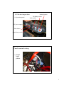
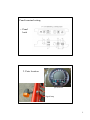
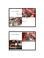
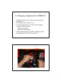
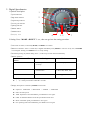
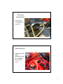
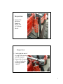
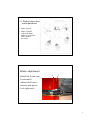
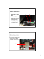
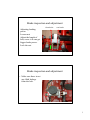
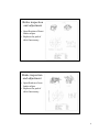
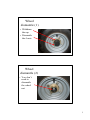
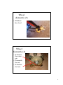
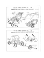
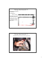
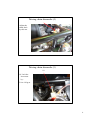
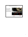
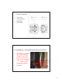
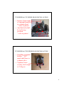
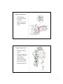
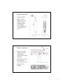
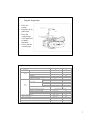
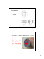
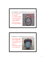
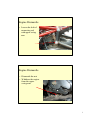
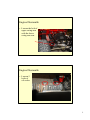
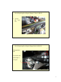
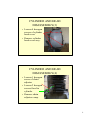
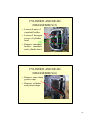
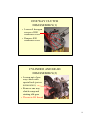
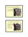
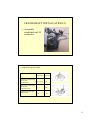
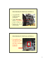
SERVICE MANUAL
Manufactured by Motive Power Industry Co., Ltd
4. Electric inspection
•1. Operation panel
Parking button
Headlamp switch
Main switch
12V power supply
Horn button
Signal lamp switch
Panel terminal wiring
• Panel
back
photo
1
Panel terminal wiring
• Panel
back
2. Parts location
speedometer
Signal lamp
2
2. Parts location
Relay
regulator
resistor
Ignition coil
2. Parts location
Starting safety device
battery
3
2. Parts location
CDI
Head lamp
Optional device
Reverse shifting safety device
Parking sensor
4
Electric inspection
• Check the
coupling,
prevent losing
connection of
the terminals.
• Spray some
anti-dust wax
if necessary.
Electric inspection
Flasher relay
starting motor relay
Head lamp & choke controller
Fuse
5
2. Charging Adjustment of BR150
• Start the engine, keep in idle speed, turn on the
headlamp.
• Disconnect the red/white wire .
• Use the pocket tester to measure the charging
current as photo shown:
1.Black (to battery).
2.Red (to wire harness).
• Adjust the idle speed to 1600 to 1800 rpm, then
the charging current shall be positive.
1
2
6
3. Ignition
• Ignition wiring
• For CDI unit,
you don’t have
to adjust the
ignition timing
7
3.1 OPERATION
1.OPERATION LAYOUT
2.. Digital Speedometer
1 1.Symbol description
①speed indication
8 2 ②high beam indicator
③signal lamp indicator
3
④reverse gear indicator
3
⑤parking indicator
⑥RESET button
⑦MODE button
⑧display area
6 4 5 7
2.Setting: Press “MODE + RESET” 2 sec., then can get into the setting procedure.
①Unit: km/h or mile/h, switched by MODE, and RESET to confirm.
②Wheel circumstance: from 1 to 3999 mm, 4 digitals individually set by RESET to increase one by one, and MODE
to next digital. Finally press MODE 2 sec. to escape setting.
③If without pressing any button during 20 sec., it will escape to main menu automatically.
④Button operation
Situation
Setting
Main menu
Button
MODE
: to next parameter
2: escape
: switch display
RESET
: digital + 1
2: no function
: no function
2: Reset RT, MAX, TRIP
MODE + RESET
l
l
2: setting parameter
『 』 means press button one time.
『 2』 means press button and hold 2 seconds.
⑤Display description: switched by MODE in main menu.
l
Sequence: SPD/TRIP → MAX/ODO → SPD/RT → SPD/TRIP
l
SPD: real time speed
l
TRIP: trip distance from last RESET, press RESET to zero again.
l
ODO: accumulated distance from this speedometer been used.
l
MAX: maximum speed, press RESET to zero again.
l
RT: operating time from last RESET, press RESET to zero again.
3.2 Steering Inspection
& Adjustment
Dismantle
• Lock tight the
bolts of steering
handle.
• Torque:0.5 kg-m
1
Steering
Inspection
• Inspect the
coupling joint
knuckle.
Maintenance
• Add grease into
upper
suspension arm
per 10,000km
from grease
valve.
2
Inspection
• Inspect the
absorber,
function
check and
oil leakage
check.
Inspection
• Lock tight the nut of
tie rod with steering
spindle support.
• Inspect the clearance
of tie rod with the
steering spindle
support.
3
Steering Inspection & Adjustment
Steering Inspection & Adjustment
• Lock tight the
bolt
• Add grease into
lower suspension
arm per
10,000km.
4
Steering Inspection & Adjustment
•
•
•
•
•
When checking the alignment of front wheel.
Keep the vehicle at flat surface
From the top view,wake sure:
C=D,and
A-B=1/8~1/4
Front
Steering Inspection & Adjustment
• Adjusting the toe-in
• Loosen unit#2 and
#3
• Rotating #4 to
adjusting the toe-in
5
3.3 Brake inspection
and adjustment
• Brake system
• Brake cylinder
• Adjust the hand
brake (to rear brake
disk) cable if
necessary
Brake adjustment
2
1
• Hand Park (Front end)
• Loosen nut#1
• Adjust bolt#2 out to
increase park power.
• Lock tight nut#1.
1
Brake adjustment
• Hand Park (Caliper
end)
• Loosen nut#1
• Adjust the cable to
front to increase
hand brake power.
• Lock tight nut#2.
1
2
Brake inspection
• Check the brake fluid
level, add it when
below “MIN” level.
MIN
2
Brake inspection and adjustment
• Adjusting braking
power.
• Loosen nut
• Adjust the length of
bolt, screw it in can get
bigger brake power.
• Lock the nut.
front brake
rear brake
Brake inspection and adjustment
• Make sure there is not
any fluid leakage
from the bolt.
3
Brake inspection
and adjustment
• Specification of front
brake caliper
• Replace the pad of
disk if necessary.
Brake inspection
and adjustment
• Specification of rear
brake caliper
• Replace the pad of
disk if necessary.
4
Wheel
dismantle (1)
• Withdraw
the cap
• Dismantle
the 4 nuts
Wheel
dismantle (2)
• You don’t
need to
dismantle
the wheel
nut
5
Wheel
dismantle (3)
• Withdraw
the wheel
Wheel
dismantle (4)
• Withdraw
the cotter
pin
• Dismantle
the nut
• Withdraw
the hub
6
2.4 Carburetor dismantle & inspection:
1. dismantle
l
l
Remove:-carburetor assembly, pipes,
cables and wires
Remove:- high-tension wire
2. adjustment
there are two screws might be adjusted to
tuning the engine intake mixture.
l
1st is the stop screw: to adjust the engine
idle speed, recommended idle speed is
1600 to 1800 rpm.
l
2nd is the air screw to adjust the air/fuel
ratio.
3.Auto by-start function check
the carburetor is equipped with auto
by-start to improve the engine cold start, it
shall be warm after the engine has been
starting for 5 minutes.
4. Float chamber function check
fuel level is controlled by float assembly,
and stopped by valve set. Whenever there
is any flooded fuel leaks, check if there is
any dirty element or valve set is worn out.
5. Whenever the carburetor is exploded, be
careful to install all the parts properly to the
original sequence.
CARBURETOR PRINCIPLE
Various
pressure
Intake
air
Functions:
1.Fuel atomization
2.Air/Fuel Ratio
3.Engine Output
To
Man
i
Fuel level
fol
d
Engine inspection
• Carburetor
Assembly
• Idle
adjustment(stop
screw)
1700±100rpm
• Pilot screw
1
IDLE ADJUSTMENT
Remarks:
1.For 4 stroke engine,more
opening turns of PS, A/F
ratio is richer.
2.Clean the jets and body
with compressed air.
怠速噴嘴
(PJ)
fuel
Pilot Screw
(PS)
怠速空氣噴嘴
(SAJ)
MAIN SYSTEM
Vacuum
piston
油針
(JN)
Body
Throttle
valve
主空氣噴嘴
(MAJ)
油針噴嘴
(NJ)
主噴油嘴
(MJ)
Remarks:
1.No leakage of vacuum
piston comp with body.
2.Keep jets and paths clean.
3.Don’t miss small parts
like O-ring, spacer … etc.
2
3.pilot screw assy.
4.vacuum piston assy.
5.jet needle
8.cover
13.main jet
14.pilot jet
15.float
19.by-start cap
20.auto by-start
3
CVT TRANSMISSION DISASSEMBLY(1)
• Loosen 9
hexagon
flange screws
of LH cover
• Remove
engine LH
cover
CVT TRANSMISSION DISASSEMBLY(2)
• Loosen nuts of
driving pulley and
clutch outer
• When installing
nuts, tighten torque
is 5.5 kg-m
1
CVT TRANSMISSION DISASSEMBLY(3)
• Remove drive face,
driving pulley assy.,
driven pulley assy.,
V-belt
Item
CVT
inspection data
Standard value ( mm )
Limit of use ( mm )
The inner dia. Of slide driving
plate
24.011~24.052
24.10
The outer dia. Of boss, movable
Driving plate
23.960.~23.974
23.940
Belt width
Clutch lining thickness
20.0~21.0
19.0
3
1.5
125.0~125.2
125.5
151
127
The outer diameter of driven
Plate sets
33.965~34.025
33.95
The inner diameter of slide
Driven plate
34.000~34.025
34.06
The outer diameter of weight
Roller set
17.920~18.080
17.40
Clutch outer inner diameter
Driven plate spring, free length
2
CVT
inspection data
Belt width
Roller dia.
Lining thickness
Outer dia
Frt pulley dia
Spring length
Engine inspection
•Transmission System
•Primary:CVT
•Final:reduction gear
•PV:CVT clutch-in
•GV:CVT top speed
3
Engine inspection
• Transmission
System
• Reverse gear
is engaged
Driving chain dismantle (1)
5
4.Dismantle 2 bolts
5.Push the reverse
box to right hand
approximately 10
mm.
4
4
Driving chain dismantle (2)
6.Dismantle the bolt(#16)
& nut.(#10)
Lock torque is:
2.5 to 3.0 kg-m
And make sure part #9
can rotate in pivot #17
7.Replace the collar (#17)
8.Assemble the engine
mount link by reverse
step 1 to 6.
Driving chain dismantle (3)
And make sure part #9 can rotate in pivot #17
5
Driving chain dismantle (4)
9.Adjust the
chain slack
by this nut.
Driving chain dismantle (5)
10
10. Lock the
lower nuts
by :
5.0 to 6.0 kg-m
6
Driving chain dismantle (6)
• When installing
the lock pin of
driving, keep the
close end forward
the Drive direction.
Close end
Open end
7
Engine inspection
• Engine layout
•Cylinder
head &
cover
1HEAD COMP. CYLINDER
2"GUIDE,EXH VALVE “
3O-RING
4"GUIDE,IN VALVE “
5VALVE EXHAUST
6VALVE INLET
7GASKET HEAD CYL.
8LOCK PIN (D10*14L)
9HEXAGON FLANGE BOLT
10STUD BOLT
11STUD BOLT
12INSULATOR CARB GASKET
13INSULATOR CARB
14IGNITION PLUG (CR7HSA)
15PLAIN WASHER
16"SPRING,VALVE “
17RETAIER VALVE SPRING
18COTTER VALVE
19"CAM,SHAFT ASSY."
20"SHAFT,EX.ROCKER ARM"
21VALVE RXKER ARM
22SCREW TOPPED ADJUSTER
23HEXAGON NUT
24"SHAFT,EX.ROCKER ARM "
25LOCK PIN
26CAMSHAFT HOLDER
27PLAIN WASHER
28HEXAGON FLANGE NUT
29CYL.HEAD COVER COMP.
30CYL.HEAD COVER
31"PACKING,CYL. HEAD COVER "
32HEXAGON FLANGE BOLT
33VALVE SEAL
34CLIP
35TUBE CYL. COMP.
1
Engine inspection
•Cylinder head inspection
•Different view of
cylinder head
Cylinder head data:
Description
Valve Clearance
(Before warm up)
IN/
EX
Standard
(mm)
Limit use
(mm)
0.08
-
EX
0.08
-
IN
11kg/700rpm
26.625
(BR150)
26.23
IN
Compression pressure
Height of the cam’s convex part
EX
Inner diameter of rocker arm shaft
Outer diameter of rocker arm shaft
Valve base angle
Outer diameter of valve stem
Inner diameter of valve guide
Clearance between valve stem and
Valve guide
26.53
26.13
IN
10.00~10.015
10.10
EX
10.00~10.015
10.10
IN
9.972~9.987
9.91
EX
9.972~9.987
9.91
IN&EX
1.0
1.8
IN
4.975~4.900
4.90
EX
4.955~4.970
4.90
IN
5.000~5.012
5.30
EX
5.000~5.012
5.30
IN
0.010~0.037
0.08
2
Engine inspection
•
•
•
•
Valve train
Valve clearance
IN:0.08mm
EX:0.08mm
CYLINDER & CYLINDER HEAD INSTALLATION
• Installing camshaft,
the valve timing
shall be adjusted
• Rotate the magneto
“T” make to RH
crankcase allied
position
MAGNETO “T”
RH crankcase mark
3
CYLINDER & CYLINDER HEAD INSTALLATION
• Ensure 2 line marks
of camshaft parallel
to cylinder head
(refer to photo)
• And the hole shall
be in the top
position
(refer to photo)
Hole in camshaft
Line marks in
camshaft
CYLINDER & CYLINDER HEAD INSTALLATION
• Installing camshaft
holder,“EX”
mark shall face to
exhaust valve
• Tighten 4 nuts
crossly, lock torque
is 2.0 kg-m
4
Engine inspection
• Oil lubricated
System (by pump
& splash)
• Make sure the oil
path is through &
clean.
Engine inspection
• Intake & Exhaust
system
• Inspect element per
1,000km, replace it
if necessary.
• If the vehicle is
often used in dusty
area, decrease the
inspection interval.
5
Engine inspection
• Exhaust muffler
• Make sure the
flange #1 is well
locked with the
cylinder head to
avoid leakage.
• Lock muffler at #4
with engine LH
cover.
Engine inspection
• Engine oil cooler
• Always clean the
cooling fin to
increase the cooling
efficiency.
• Replace the oil filter
per 5,000 kms.
• Lock torque:10 N-m
• Inspect the oil
leakage.
6
Engine inspection
• Pulse air
system
• Keep the air-in
path clean.
• Keep the
vacuum pipe
well connected
to intake
manifold,
• Never jam the
vacuum pipe.
Cylinder & piston inspection data:
Part name /description
Cylinder head
Bore
Cylinder
Standard
Limit
( mm )
( mm )
flatness
57.490~57.510
57.600
Curve
-
0.05
Cylindrility
-
0.05
Roundness
Clearance b/w Piston and
-
0.05
Piston ring
lst ring
0.10
2 n d ring
0.10
Clearance of cutting
lst ring
0.50
section
2 n d ring
0.50
Piston/
---
Piston ring
Piston outer diameter
Measuring location of piston outer dia.
Clearance b/w piston and cylinder
Piston pin hole inner dia
Piston pin hole inner diameter
Piston pin outer diameter
Clearance between piston and piston pin
57.475~57.490
57.400
5 mm from the lower end of skirt
0.025~0.035
0.10
15.006~15.012
15.030
14.990~14.992
12.96
0.020~0.017
0.025
15.010~15.028
15.060
Connecting rod small end inner dia
7
Engine inspection
• Cylinder
CYLINDER & CYLINDER HEAD INSTALLATION
• Notice the marks
upon piston
• “IN” mark shall in
the intake direction ;
“EX” mark shall in
the exhaust direction
To intake
IN
To exhaust
EX
8
CYLINDER & CYLINDER HEAD INSTALLATION
• Piston rings shall
be installed
according to marks
• 1st ring is marked
“1R” ; 2nd ring is
marked “RN”
• The marks shall
face to piston head
1st ring “1R”
2nd ring “RN”
CYLINDER & CYLINDER HEAD INSTALLATION
Allied to 120°
• The opening end of
piston rings shall
face to intake valve
and allied to 120
degree
• And shall not allied
to the piston pin
9
Engine Dismantle
• Loosen the bolt of
connecting rod
with upper swing
arm.
Engine Dismantle
• Dismantle the nut
• Withdraw the engine
from the upper
swing arm.
1
Engine Dismantle
• Loosen the bolt of
upper swing arm
with the lower
swing arm rear.
Engine Dismantle
• Loosen 2
bolts of
oil cooler
2
OP of Replacing Rear Engine Hanger Collar for BR150
1
1. Loosen
the lock
nut.
OP of Replacing Rear Engine Hanger Bush for BR150
2
2.Dismantle the
bolt
3.Loosen the nut.
Lock torque is:
11.0 kg-m
3
3
Muffler DISASSEMBLY(1)
• Loosen 2
bolts of
muffler with
cylinder head
Muffler DISASSEMBLY(2)
• Loosen 1
hexagon bolt
of muffler
with LH
cover
• Remove
muffler
4
Air cleaner removal (1)
• Loosen 9
hexagon
flange screws
of LH cover
• Remove
engine LH
cover
Air cleaner removal (2)
• Outside end
is sponge,
clean it if
necessary
• Inside end is
paper element,
replace it if
necessary
5
MAGNETO DISASSEMBLY(1)
• Loosen 2 hexagon
screws and 2 C-R
recess pan hd.
tapping screws
• Remove fan cover
MAGNETO DISASSEMBLY(2)
• Loosen 4 hexagon
screws of cooling
fan
• Remove cooling
fan
6
MAGNETO DISASSEMBLY(3)
• Loosen nut of
magneto
• When installing,
tighten lock torque
is 5.5 kg-m
MAGNETO DISASSEMBLY(4)
• Pull out the
magneto with
special tool
• part no:
S620402G01A
☆tool should be
tighten lock
7
MAGNETO DISASSEMBLY(5)
• Loosen 3
hexagon
screws of
stator
• Remove
stator
Stator
flywheel
cooling fan
CYLINDER AND HEAD
DISASSEMBLY(1)
• Loosen 1 hexagon
screw and 2 tapping
screws of cooling
cowl(2)
• Remove cooling
cowl(2)
8
CYLINDER AND HEAD
DISASSEMBLY(3)
• Loosen 4 hexagon
screws of cylinder
head cover
• Remove cylinder
head cover assy.
CYLINDER AND HEAD
DISASSEMBLY(4)
• Loosen 1 hexagon
screw of chain
adjuster
• Loosen 2 hexagon
screws fixed in
cylinder
• Remove chain
adjuster comp.
9
CYLINDER AND HEAD
DISASSEMBLY(5)
• Loosen 4 nuts of
camshaft holder
• Loosen 2 hexagon
screw of cylinder
head
• Remove camshaft
holder、camshaft
and cylinder head
CYLINDER AND HEAD
DISASSEMBLY(6)
• Remove cam chain
guide comp.
• Remove cylinder
and piston rings
10
ONE WAY CLUTCH
DISASSEMBLY(1)
• Loosen 8 hexagon
screws of RH
crankcase cover
• Remove RH
crankcase cover
CYLINDER AND HEAD
DISASSEMBLY(2)
• Loosen nut of one
way clutch with
special tool (part no:
S620401G015)
• Remove one way
clutch comp and
starting idle gear
• The nut is LH thread
11
OIL PUMP DISASSEMBLY(1)
• Loosen 2 C-R
recess screws of oil
separator
• Remove oil
separator
OIL PUMP DISASSEMBLY(2)
• Loosen nut of oil
pump driving gear
• Remove oil pump
driving gear and
chain
12
OIL PUMP DISASSEMBLY(3)
• Loosen 2 hexagon
screws of oil pump
• Remove oil pump
CRANKSHAFT DISASSEMBLY(1)
• Loosen 2 hexagon
screws of RH
crankcase
• Remove RH
crankcase with
plastic hammer
13
CRANKSHAFT DISASSEMBLY(2)
• Pull out crankshaft
from LH crankcase
• Remove camshaft
chain
CRANKSHAFT INSTALLATION(1)
• Put camshaft chain
in LH crankcase
14
CRANKSHAFT INSTALLATION(2)
• Assemble
crankshaft in LH
crankcase
Crankshaft inspection data:
ITEM
Standard
value(mm)
Limit of
use.(mm)
Clearance of connecting
rod big end
axle direction
0.10~0.35
0.55
Clearance of connecting
rod big end
vertical direction
------
0.04
0.03
0.10
Swingness of the crank
shaft journal.
15
CRANKSHAFT INSTALLATION(3)
• Assemble RH
crankcase into
crankshaft
• Tight 2 hexagon
screws
• (torque is1.0kg-m)
• Replace the oil seal
and packing.
CRANKSHAFT INSTALLATION(4)
• To avoid the oil
seal detected, shall
assemble the oil
seal after crankshaft
is fixed in
crankcase
16
SERVICE MANUAL
Manufactured by Motive Power Industry Co., Ltd
Content
Chapter 1 :
n
n
Service notation
Specification
Locking torque
Chapter 2: Engine dismantle & inspection
n
n
n
n
Engine dismantle
Engine inspection
Transmission dismantle & inspection
Carburetor adjustment
Chapter 3 : Chassis inspection
n
n
n
n
Operation
Steering inspection & adjustment
Brake inspection & adjustment
Installation
Chapter 4 : Electric
n
n
n
n
Parts location
Charging inspection & adjustment
Ignition inspection
Wiring diagram
PREFACE
This manual offers all service specialists with the technological
procedures of maintenance, repairing for BR-150 show those whom may
concern how to maintain in detail, repair, change parts, troubleshoot and
reassemble, etc.
At every important section we illustrate by assembly, explosion
diagrams and photographs, if necessary, please check the diagrams
already shown.
Though we have tried our best, please kindly instruct us any
faults found in this manual.
MOTIVE POWER INDUSTRY CO., LTD.
Name
TYPE
BUGXTER SPECIFICATION
BR-150
FRAME
BR-150
DIMENSION
TOTAL LENGTH
2215 mm
TOTAL WIDTH
1365 mm
TOTAL HEIGHT
1480 mm
STEEL
SUSPENSION SYSTEM
FRONT
SINGLE A ARM
REAR
SWING ARM
TRANSMISSION
RPIMARY RATIO
1
WHEELBASE
DRY WEIGHT
FRONT
1510 mm
SECONDARY RATIO
263KG
CLUTCH
REAR
154 KG
FRONT
TOTAL
LOAD
263 KG
REAR
40/16*42/13
C.V.T.
TIRE
109 KG
19 ×7-8
255/60-10
2 PERSONS(110KG)
BRAKE SYSTEM
VEHICLT PERFORMANCE
FRONT
DISC BRAKE
TOP SPEED
70KM/H
REAR
DRUM BRAKE
FUEL CONSUMPTION
25KM/L
LIGHT
CLIMBING ABILITY
HEAD
12V-35W/35W*2
25°
LIGHT(H/L)
TAIL LIGHT
12V-5W
CYCLE
4
BRAKING LIGHT
12V-21W
FUEL
UNLEADED
TURN LIGHT
12V-10W
CYLINDER NUMBER
1
ARRANGEMENT
HORIZONTAL
150.1 cc
DISPLACEMENT
BORE
φ57.5 mm
STROKE
COMPRESSION RATIO
MAX. POWER/RPM
AMX. TORQUE/RPM
IDLE RPM
IGNITION
SPARK PLUG
COOLING
STARTER
FUEL MIXING
LUBRICATION
57.8 mm
9.4 : 1
7.5kw/7750rpm
10.2N-M/6500rpm
1700±100 RPM
CDI
NGK CR7HSA
FORCE AIR & OIL
ELECTRIC
OIL PUMP
SEPARATED
1.1 The operation notice:
1. Always replace gasket, O ring, cotter, pins and clip whenever reassembled.
2. When tighten screws or nuts, lock tightly as per specified locking torque, and in the sequence of
cross direction.
3. Use PGO, or PGO Recommended parts.
4. After dismantling please wash all parts necessary for checking and grease all
contact surface when reassembling.
5. Use grease recommended by P.G.O.
6.When removing battery, please dismantle the negative pole (-) first, when
assembling please connect positive pole (+) first.
6. Before installing a new fuse, confirm the specification is correct or not.
7.After reassembling, please re-check that all connecting point, locking parts,
circuits, polar characteristics are good, before selling out.
1.2 TORQUE VALUE
1. Engine:
NO
Locking location
Q’TY
Thread dia. (mm)
Locking torque (kg-m)
1 Cylinder head bolt A (intake)
2
6
0.9~1.1
2 Cylinder head bolt B (Exhaust)
2
8
2.2
3 Cap, oil filter graze
1
30
1.5~2.0
4 Flange nut, cam shaft base
4
8
2.2
5 Fixing nut, air valve adjustment
2
5
0.7
6 Guiding pin bolt, inner chain adjustment
1
6
0.9~1.1
7 Oil bolt
1
8
1.7~2.0
8 Fixing nut, clutch outer
1
12
5.0~6.0
9 Nut, driven plate
1
12
5.0~6.0
10 Nut, driving plate
1
12
5.0~6.0
11 Spark plug
1
10
1.2~1.3
12 Nut, drive clutch
1
22
9.0~10.0
13 Screw, inner chain adjuster
1
6
0.4~0.6
2.General parts please refer the following table:
NO
Item
Torque (kgf- m)
1
5mm bolt and nut
0.45-0.6
2
6mm bolt and nut
0.8-1.2
3
8mm bolt and nut
1.8-2.5
4
10mm bolt and nut
3.4-4.0
5
12mm bolt and nut
5.0-6.0
6
5mm screw
0.35-0.5
7
6mm screw
0.7-1.1
8
6mm flange bolt and screw
1.0-1.4
9
7mm flange bolt and screw
1.0-1.4
10 8mm flange bolt and screw
2.0-3.0
11 10mm flange bolt and screw
3.0-4.0
Remark
Greasing on thread
Left thread
3.Locking Torque Standard (Chassis)
No
Locking location
Qty
Thread dia
(mm)
Kg-m
1
Wheel nut
16
10
6.0
2
Wheel axle nut
1
16
8.0
3
Front absorber bolt
4
10
6.0
4
Lower suspension arm bolt
2
10
6.0
5
Steering handle bolt
6
3
0.5
6
Seat belt fixture
5
8
3.0
7
Upper suspension arm
2
8
3.0
8
Tie rod nut
4
10
5.0
9
Roll cage bar
6
8
4.0
10 Rear swing arm, lower
2
12
6.0
11 Engine hanger with frame
2
10
3.5~4.5
12 Engine hanger with engine
1
10
3.5~4.5
13 Rear absorber
4
10
3.5~4.5
14 Connecting rod
4
8
3.0
15 Chain adjusting bolt, upper
1
12
6.0
16 Chain adjusting bolt, lower
1
12
6.0
17 Brake caliper fixture
6
8
2.5~3.0
18 Brake hose bolt
6
8
2.5~3.0
19 Reverse gear shaft
1
16
11.0
20 Rear sprocket
4
8
3.0
21 Brake disk
8
8
3.0
Remark
1.3 In order to achieve safe riding, good performance and reduce pollution, please execute the following
recommended maintenance table base upon average driving condition. Driving in unusual dusty
areas, require more frequent servicing.
MONTHS/DISTANCE(IN KM)FOR CHECKING
Item
Engine oil *
Oil Filter *
Coarse oil filter* (on oil
draining bolt)
Oil cooler
Air filter *
Gear oil *
Brake performance
Brake oil, disk, pad,
hose, master cylinder
Clutch linings *
Tires
Checking Content
Replace (800cc, total 900cc)
Replace
Clean or replace it if necessary
Clean or replace it if necessary
Replace it if required
Replace (90cc, total 110 cc)
Leaking and function check
Leaking and worn -out check or
replace it if necessary
Check or replace it if necessary
Worn-out check or replace it if
necessary
Wheel bearing *
Fasten tightly if loosen
Driving chain *
Lubricate & check the slack
Chassis suspension arm, Check looseness. Add grease if
spindle *
required
Steering joint & rod *
Check looseness. Adjust it if
required
Absorber *
Leaking and function check
Parking
Function check or replace it if
required
Nuts, bolts, fasteners
Tighten it if required
Battery
Make sure that the voltage
stayed over 12.8V. Recharge the
battery it required.
Clear the poles.
Valve gap *
Spark plug *
V belt *
Fuel feeding system *
Engine idle speed *
Carburetor idle A/F
Adjustment *
Check and adjust when engine
is cool (0.08mm for IN & EX)
Clear or replace if required
Worn out check or replace if
necessary.
Crack and blockage check.
Replace it if necessary.
1700±100 rpm
Check and adjust referring to
CO/HC Percentage.
1 or
3 or
6 or
9 or 12 or 15 or 18 or
300 km 3000k 5000k 8000k 10000k 13000k 15000k
R
Replace it per 1,000km
R
Replace it per 5,000km
C
Clean it per 3,000km or replace it if required
I
R
I
I
I
I
C
C
I
I
C
Replace it per 1,000km
R
R
I
I
I
I
I
I
I
I
I
I
I
I
I
I
I
I
I
I
I
I
I
I
I
I
C,A,L
C,A,L
I
I
I
I
C,A,L
C,A,L
I
I
I
I
C,A,L
C,A,L
I
I
R
I
I
I
I
I
I
I
I
I
I
I
I
I
I
I
I
I
I
I
I
I
I
I
I
I
I
I
I
I
I
Adjust it when necessary
I
I
I
I
P
P
P
I
I
I
A
A
A
A
A
A
A
A
A
A
A
A
A
A
A: adjust
C: clean I: inspect, clean or replace if necessary
L: lubricate R: replace
1. Items with “*” mark indicate our recommendation to have it done by PGO dealer.
2. “P” denotes that function check or replace it when the engine performance reduces significantly.
NOTE 1:
The engine oil shall be changed completely after run- in period 300 km or one month later. This can
make sure the engine runs smoothly.
NOTE 2:
The exchange of brake fluid
1. After disassembling of brake main cylinder or caliper, do change the new fluid.
2. Check the fluid level often, refill if necessary.
3. Change the oil seal of main cylinder and caliper every two years.
4. Change the brake fluid hose every four years.
1
3
2
4
5
7
6
8
1
9
10
11
13
12
14
15
2
16
17
19
18
20
21
3
Content
Chapter 1 :
n
n
Service notation
Specification
Locking torque
Chapter 2: Engine dismantle & inspection
n
n
n
n
Engine dismantle
Engine inspection
Transmission dismantle & inspection
Carburetor adjustment
Chapter 3 : Chassis inspection
n
n
n
n
Operation
Steering inspection & adjustment
Brake inspection & adjustment
Installation
Chapter 4 : Electric
n
n
n
n
Parts location
Charging inspection & adjustment
Ignition inspection
Wiring diagram