1
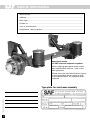
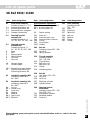
Service manual for
SAF axles and
Suspension Assemblies
Edition 8/2002
Service
Vehicle information
Manufacturer..............................................................................................................
Address.......................................................................................................................
Body type...................................................................................................................
Chassis no...................................................................................................................
Year of manufacture.................................................................................................
Registration, date-in-service.....................................................................................
Spare parts service
for SAF axles and suspension systems
When ordering spare parts quote correct
axle identification serial no., refer to the
axle type plate.
Please enter the axle identification figures
in the type plates shown below so that
correct specification are available when
required.
10114GB Edition 0802
Type plate for axle beam assembly
2
Contents
Page
SAF axle indentification
General service instructions
Notes
2
5
53-54
SAF axle types SK RS / RZ 9042 / 11242 / 9037 / 11037
Service schedule for SAF axle types SK RS / RZ 9042 / 11242
Service chart for SAF axle types SK RS / RZ 9042 / 11242
Spare parts and torque wrench settings SK RS / RZ 9042 / 11242
6
7
8-9
Service schedule for SAF axle types SK RS / RZ 9037 / 11037
Service chart for SAF axle types SK RS / RZ 9037 / 11037
Spare parts and torque wrench settings SK RS / RZ 9037 / 11037
10
11
12-13
SAF axle types SK RS / RZ 9030 / 11030 / RZ 12030
Service schedule for SAF axle types SK RS / RZ 9030 / 11030 / RZ 12030
Service chart for SAF axle types SK RS / RZ 9030 / 11030 / RZ 12030
Spare parts and torque wrench settings SK RS / RZ 9030 / 11030 / RZ 12030
14
15
16-17
SAF axle types SK RS / RZ 12242
Service schedule for SAF axle types SK RS / RZ 12242
Service chart for SAF axle types SK RS / RZ 12242
Spare parts and torque wrench settings SK RS / RZ 12242
18
19
20-21
SAF axle types K RS / RZ 14242 / 16242
Service schedule for SAF axle types K RS / RZ 14242 / 16242
Service chart for SAF axle types K RS / RZ 14242 / 16242
Spare parts and torque wrench settings K RS / RZ 14242 / 16242
22
23
24-25
SAF axle types with disc-brakes SK RS / RZ 9022 K / 11222 K / 9019 K / 11019 K
Service schedule for SAF axle types SK RS / RZ 9022 K / 11222 K / 9019 K / 11019 K
Service chart for SAF axle types SK RS / RZ 9022 K / 11222 K / 9019 K / 11019 K
Spare parts and torque wrench settings SK RS / RZ 9022 K / 11222 K / 9019 K / 11019 K
26
27
28-29
Trailing steering axles - adjustment
30-31
Spare parts and torque wrench settings SK RLS 9042 / 11242
Spare parts and torque wrench settings SK RLZ 9037 / 11037
Spare parts and torque wrench settings SK RLZ 9030 / 11030
32-33
34-35
36-37
Spare parts and torque wrench settings
Air Suspension Series M
38-39
Spare parts and torque wrench settings
Air Suspension Series O
40-41
Spare parts and torque wrench settings
Air Suspension Series U
42-43
10114GB Edition 0802
Trailing steering axles
3
Contents
Page
General information
Tightening instruction for pivot clamping bolt assembly
44
Adjusting the ride height
45
Braking system - checking and adjustment
46
10114GB Edition 0802
HALDEX automatic slack adjuster
4
47-48
S-ABA automatic slack adjuster
49
Track control
50
Wheel bearings - adjustment
51
Torque wrench settings
52
General service instructions
for SAF axles and suspension units
1.
Instructions and tips for vehicle operation
In order to maintain the operation and road safety of the vehicle, the maintenance operations
prescribed by SAF must be carried out regularly at the specified intervals
(see "Maintenance instructions").
Furthermore, ensure that
1.1 the disc brake is not overheated due to continuous operation as otherwise irreparable damage
to the surrounding components – in particular the wheel bearings – cannot be ruled out. This
can impair the operational and road safety of the vehicle and represent a serious hazard for
man and machine.
1.2 the compatibility of the brakes on the truck-trailer combination is checked. For reliable braking
and uniform brake lining wear, the brake systems of the two vehicles must be matched to one
another before starting operation
1.3 the parking brake is not applied immediately when the brakes are hot as the resulting different
stress fields can damage the brake discs
1.4 the drum brakes are not overheated as this will result in a dangerous reduction in braking
efficiency
1.5 the maximum permissible axle loads and speeds are not exceeded
1.6 the cargo is evenly distributed over the loading area and safely secured
1.7 on vehicles with air suspension, the air bags are always fully pressurised before starting a journey
1.8 the prescribed wheel rims and tyre sizes are employed
1.9 the tyres have the prescribed inflation pressure
1.10 your driving style is matched to the road conditions
1.11 axle supports are used when loading/unloading construction machinery
1.12 the use of auxiliary trailer braking facilities (trailer underrun brake) is not permitted.
2.
Vehicle safety
2.1 The daily check of the vehicle for road safety before starting a journey is the responsibility of
the driver.
2.2 Modifications to the suspension and braking system are strictly forbidden.
2.3 Compliance with the specified permissible axle loads, specifications in the vehicle operating
permit, vehicle inspection intervals and the regular maintenance intervals is the responsibility
of the vehicle owner.
2.4 We strongly recommend fitting only SAF approved replacement parts and spare parts which
are covered by SAF product liability. These products have been thoroughly tested by SAF for
safety, functionability and suitability. Fitting of these parts guarantees not only safety on the
roads but satisfies the legal operational requirements. SAF is not in a position to judge whether
those products from other companies represent a safety risk for SAF axles and systems.
3.
Warranty
3.1 Warranty claims will only be accepted as long as the operating and maintenance instructions
have been complied with and if SAF approved spare parts have been fitted.
3.2 Warranty claims must be reported to SAF before starting the work.
3.3 The warranty period is 12 months after the vehicle registration date or after the start of
operation of the vehicle.
Service and spare parts
A close-knit service network of SAF partner companies is at your disposal for technical advice
on SAF axles and suspension systems as well as for supplying approved SAF spare parts
(see back cover or brochure "SAF service stations").
In case of repair we strongly recommend fitting only SAF original parts for those reasons
mentioned in point 2.4.
SAF axles and suspension units are subject to continuous further development; the data
and drawings contained in the manual may therefore differ from the details given in the
operating permit.
The contents of the manual does not constitute the basis for a legal claim.
Reprinting, reproduction or translation in whole or in part is not permitted.
5
The issue of this publication invalidates all earlier maintenance and repair manuals.
10114GB Edition 0802
4.
Service schedule
for SK RS / RZ 9042 / 11242 axles and suspension units
(steering axle see p. 30-33)
Service schedule
whichever comes first
Mileage intervals
>
Time intervals
>
Periodic checks
After first
5,000 km every
every
every
or
30,000 km 90,000 km 150,000 km
every
every
every
after first
month 3 months 6 months 12 months
Mechanical check
Note:
Torque check wheel nuts after the first 50 km and 150 km
(and after every wheel removal).
Torque check all nuts and bolts to recommended setting.
Hub end-float adjustment not required.
Pack wheel bearings with fresh grease after 500,000 km or
50 months, whichever comes first. Check condition of taper
roller bearings and replace, if necessary.
Lubricate camshaft bearings after every brake lining
replacement, however, at least every 12 months.
Visual inspection
•
•
for wear/damage
Check suspension components for wear, fluid leakage
and damage
Check brake linings for wear
Check camshafts for free movement
Check slack adjusters for correct function
Check braking system for leaks (brake applied)
Check air suspension for air leaks
Check air suspension bellows for damage
Check piston surface for contamination and clean,
if necessary
Check parabolic springs for damage, scoring and corrosion
Check self steering axle for correct function
Check tyre wear and tracking (if required)
•
•
Check wheel brakes for correct adjustment
Check service brake and hand brake efficiency
•
•
Check truck-trailer combination for brake compatibility
Check service brake pressure to manufacturer’s
recommendation
•
Check air suspension for correct ride height.
With 2 levelling valves, the max. permissible bellows
pressure difference (LH to RH vehicle side) is 0.2 bar.
•
10114GB Edition 0802
Safety inspection
6
•
•
Special service conditions
Vehicles with long standing periods:
Vehicles used under extreme conditions:
service at specified time intervals
service at suitably reduced intervals
Warranty claims will only be accepted as long as the operating and maintenance instructions
have been complied with and if SAF approved spare parts have been fitted.
Service chart
for SK RS / RZ 9042 / 11242 axles
Hub end-float setting. Lubricant.
Hub end-float adjustment is not required.
Pack wheel bearings with fresh grease after
500,000 km or 50 month, whichever comes first.
Check condition of taper roller bearings and
replace, if necessary.
Replace O-ring (39) and fit the wheel cap.
After brake relining, lubricate camshaft bearings
whilst rotating the camshaft through 360° several
times.
Do not disassemble the wheel bearing assembly.
Use a vacuum cleaner to remove brake dust.
Never use pressurised cleaning devices or
cleaning fluids on the brake drum and hub.
Clean stub axle and apply fresh SAF fitting paste.
Lubricant specification:
Wheel bearings:
SAF parts no. 4 387 0011 05
Camshaft:
SAF parts no. 4 387 0011 05
Stub axle:
SAF parts no. 4 387 0015 06
SAF fitting paste
Brake anchor bracket ball:
SAF parts no. 4 387 0007 00
Copper paste
424.0
d2
2. Rep.-Stufe
2nd
oversize
422.0
d1
1. Rep.-Stufe
1st
oversize
420.0
d0
LH direction of travel - LH thread.
RH direction of travel - RH thread.
Pretighten to 150 Nm whilst rotating drum.
For final torque, continue tightening through
one more scale line (10 °).
Hub nuts with LH threads are marked with
a groove milled into the hex outside.
Normalmaß
nominal
size
Hub nut tightening
BRAKE type SNK 420
Max. permissible turned brake drum bore:
424.0 mm
Brake drum bore with max. permissible wear:
425.0 mm
SAF approved brake linings:
BERAL 1541, BREMSKERL 6386
Turn new brake linings to brake drum bore dimension + 0.3 mm.
When renewing rivets, observe the manufacturer’s instructions regarding the brake lining.
SAF parts no,
brake lining
Brake drum / brake lining
refacing stages in mm
Brake linings
Nominal size
1st oversize
2nd oversize
d0-420.0
d1-422.0
d2-424.0
SNK 420
x 180
1 057 0060 00
1 057 0061 00
20.6
20.0
21.6
21.0
22.6
22.0
x 200
1 057 0066 00
1 057 0067 00
20.6
20.0
21.6
21.0
22.6
22.0
Assembly tools
9042 / 11242
Hub nut spanner
Brake shoe clamping device
Brake drum fixing flanges
Wheel bearing inserter
SAF parts no.
1
3
3
3
012
349
434
434
0024
1001
1040
1043
00
00
01
00
Rivets
DIN 7338
rivet
number per axle
4
64
B 8 x 15
10114GB Edition 0802
Brake
size
7
Spare parts
Exploded view of SK RS / RZ 9042 / 11242 axle assembly
Torque wrench settings
Use torque wrench.
The use of impact
wrenches is not accepted.
U-bolts:
(diagonally in
three stages)
M 24 / 700 Nm
M 22 / 650 Nm
M 20 / 500 Nm
Wheel nuts:
Spigot-hub-centred fixing:
M 22 x 1.5 / 600 Nm
Bolt-centred fixing:
M 22 x 1.5 / 430 Nm
091
94
98
97
Shock absorber:
M 24 / 400 Nm
96
92
93
29
30
31
34
95
38
27.3
99
40
40.1
94
38.1
39
90
89.1
41
27.2
081/082
87
27
73
66
65
88.1
18.3
64
70
88
86
85.1
72
18
010
71
89.2
89.3
12
75
15
18
74
6.1
Type
plate
Typenschild
6.2
6
25
059
4.1
10114GB Edition 0802
3
8
5
4
78
01
20
76.2
76
19
22/22.1
Production number
(right/direction of travel)
List of spare parts
SK RS / RZ 9042 / 11242
Item
Parts designation
Item
01
Axle beam assembly
including items 3 - 6, 010, 19,
22 - 22.1, 25
Spherical mounting plate
Protection plug
Protection plug (axle tube)
Ball
Camshaft bearing, brake carrier side
Riffle bolt
Hex nut
64
71
72
73
Lining service group
including items 71, 72, 73
Brake lining, cam roller side
Brake lining, ball side
Rivet
Camshaft bearing assembly,
linkage adjustment side
including items 12, 15, 18
Camshaft bearing
Hex bolt
Bellows
74
75
Spring clip
Return spring
76
76.2
78
with ABS
Bracket sensor
Hex bolt
ABS sensor
010
12
15
18
18.3
19
20
22
22.1
25
27
27.2
27.3
29
30
Brake lining wear gauge
O-ring - Hub nut
O-ring - Stub axle
Hub nut, RH thread
Hub nut, LH thread
Brake cylinder support
Hub unit, complete
with item 27.2
Repair kit including items
27.3, 38 - 39
Bearing grease
Brake drum
31
34
Wheel bolt assembly
including items 31 - 34
Riffle bolt
Wheel nut
38
38.1
39
Inner seal ring
Outer seal ring
O-ring - Hub cap
40
40.1
Hub cap, complete with items 39, 41
Hub cap, complete with pole wheel
and items 39 - 41
Plug
41
059
Brake assembly
including items 64, 74 - 75
65
66
70
Brake shoe assembly
including items 65, 71 - 73
Brake shoe with item 66
Cam roller
081
Camshaft assembly (LH)
including items 18.3, 85.1 - 88.1
082
85.1
86
87
88
88.1
Camshaft assembly (RH)
including items 18.3, 85.1 - 88.1
Disc spring
Spring clip
Washer
Washer
Spring clip
89.1
89.2
89.3
with automatic adjustment
Automatic slack adjuster
Anchor plate, RH
Anchor plate, LH
90
Return spring
091
92
93
94
95
96
97
98
Dust cover assembly
including items 92 - 98, 99
Dust cover, RH
Dust cover, LH
Plug
Cable clamp
Hex bolt
Clamp
Plug
99
Rubber grommet, ABS
When ordering spare parts quote correct axle identification serial no., refer to the axle
type plate.
10114GB Edition 0802
3
4
4.1
5
6
6.1
6.2
Parts designation
9
Service schedule
for SK RS / RZ 9037 / 11037 axles and suspension units
(steering axle see p. 34-35)
Service schedule
whichever comes first
Mileage intervals
>
Time intervals
>
Periodic checks
After first
5,000 km
every
every
every
or
30,000 km 90,000 km 150,000 km
every
every
every
after first
month 3 months 6 months 12 months
Mechanical check
Note:
Torque check wheel nuts after the first 50 km and 150 km
(and after every wheel removal).
Torque check all nuts and bolts to recommended setting.
Hub end-float adjustment not required.
Pack wheel bearings with fresh grease after 500,000 km or
50 months, whichever comes first. Check condition of taper
roller bearings and replace, if necessary.
Lubricate camshaft bearings after every brake lining
replacement, however, at least every 12 months.
Visual inspection
•
•
for wear/damage
Check suspension components for wear, fluid leakage and
damage
Check brake linings for wear
Check camshafts for free movement
Check slack adjusters for correct function
Check braking system for leaks (brake applied)
Check air suspension for air leaks
Check air suspension bellows for damage
Check piston surface for contamination and clean,
if necessary
Check parabolic springs for damage, scoring and corrosion
Check self steering axle for correct function
Check tyre wear and tracking (if required)
•
•
Check wheel brakes for correct adjustment
Check service brake and hand brake efficiency
•
•
Check truck-trailer combination for brake compatibility
Check service brake pressure to manufacturer’s
recommendation
•
Check air suspension for correct ride height.
With 2 levelling valves, the max. permissible bellows
pressure difference (LH to RH vehicle side) is 0.2 bar.
•
10114GB Edition 0802
Safety inspection
•
•
Special service conditions
Vehicles with long standing periods:
Vehicles used under extreme conditions:
service at specified time intervals
service at suitably reduced intervals
Warranty claims will only be accepted as long as the operating and maintenance instructions
have been complied with and if SAF approved spare parts have been fitted.
10
Service chart
for SK RS / RZ 9037 / 11037 axles
Hub end-float setting. Lubricant.
Hub end-float adjustment is not required.
Pack wheel bearings with fresh grease after
500,000 km or 50 month, whichever comes first.
Check condition of taper roller bearings and
replace, if necessary.
Replace O-ring (39) and fit the wheel cap.
After brake relining, lubricate camshaft bearings
whilst rotating the camshaft through 360° several
times.
Do not disassemble the wheel bearing assembly.
Use a vacuum cleaner to remove brake dust.
Never use pressurised cleaning devices or
cleaning fluids on the brake drum and hub.
Clean stub axle and apply fresh SAF fitting paste.
Lubricant specification:
Wheel bearings:
SAF parts no. 4 387 0011 05
Camshaft:
SAF parts no. 4 387 0011 05
Stub axle:
SAF parts no. 4 387 0015 06
SAF fitting paste
Brake anchor bracket ball:
SAF parts no. 4 387 0007 00
Copper paste
371.0
d2
2. Rep.-Stufe
2nd
oversize
369.0
d1
1. Rep.-Stufe
1st
oversize
367.0
d0
LH direction of travel - LH thread.
RH direction of travel - RH thread.
Pretighten to 150 Nm whilst rotating drum.
For final torque, continue tightening through
one more scale line (10 °).
Hub nuts with LH threads are marked with
a groove milled into the hex outside.
Normalmaß
nominal
size
Hub nut tightening
BRAKE type SNK 367
Max. permissible turned brake drum bore:
371.0 mm
Brake drum bore with max. permissible wear:
372.0 mm
SAF approved brake linings:
BERAL 1561, BREMSKERL 6386
Turn new brake linings to brake drum bore dimension + 0.3 mm.
When renewing rivets, observe the manufacturer’s instructions regarding the brake lining.
SAF parts no.
brake lining
SNK 367
Brake drum / brake lining
refacing stages in mm
Brake linings
Nominal size
1st oversize
2nd oversize
d0-367.0
d1-369.0
d2-371.0
x 180
1 057 0068 00
1 057 0069 00
21.1
20.5
22.1
21.5
23.1
22.5
x 200
1 057 0070 00
1 057 0071 00
21.1
20.5
22.1
21.5
23.1
22.5
Assembly tools
9037 / 11037
Hub nut spanner
Brake shoe clamping device
Brake drum fixing flanges
Wheel bearing inserter
Puller for MS bushing
Bushing tool for MS bushing
SAF parts no.
1 012 0024 00
3 349 1001 00
3 434 1040 01
3 434 1059 00
1 434 1056 00
1 434 1055 00
Rivets
DIN 7338
rivet
number per axle
4
64
B 8 x 15
10114GB Edition 0802
Brake
size
11
Spare parts
Exploded view of SK RS / RZ 9037 / 11037 axle assembly
Torque wrench settings
Use torque wrench.
The use of impact
wrenches is not accepted.
U-bolts:
(diagonally in
three stages)
M 24 / 700 Nm
M 22 / 650 Nm
M 20 / 500 Nm
Wheel nuts:
Spigot-hub-centred fixing:
M 22 x 1.5 / 600 Nm
Bolt-centred fixing:
M 22 x 1.5 / 430 Nm
091
94
98
97
Shock absorber:
M 24 / 400 Nm
96
92
93
29
30
31
34
95
38
27.3
99
40
40.1
94
38.1
39
90
89.1
41
27.2
081/082
87
27
73
66
65
88.1
18.3
64
70
88
86
85.1
72
18
010
71
89.2
89.3
12
75
15
18
74
6.1
Type
plate
Typenschi
6.2
6
25
059
4.1
10114GB Edition 0802
3
12
5
4
78
01
20
76.2
76
19
22/22.1
Production number
(right/direction of travel)
List of spare parts
SK RS / RZ 9037 / 11037
Item
Parts designation
Item
01
Axle beam assembly
including items 3 - 6, 010, 19,
22 - 22.1, 25
Spherical mounting plate
Protection plug
Protection plug (axle tube)
Ball
Camshaft bearing, brake carrier side
Riffle bolt
Hex nut
64
71
72
73
Lining service group
including items 71, 72, 73
Brake lining, cam roller side
Brake lining, ball side
Rivet
Camshaft bearing assembly,
linkage adjustment side
including items 12, 15, 18
Camshaft bearing
Hex bolt
Bellows
74
75
Spring clip
Return spring
76
76.2
78
with ABS
Bracket sensor
Hex bolt
ABS sensor
010
12
15
18
18.3
19
20
22
22.1
25
27
27.2
27.3
29
30
Brake lining wear gauge
O-ring - Hub nut
O-ring - Stub axle
Hub nut, RH thread
Hub nut, LH thread
Brake cylinder support
Hub unit, complete
with item 27.2
Repair kit including items
27.3, 38 - 39
Bearing grease
Brake drum
31
34
Wheel bolt assembly
including items 31 - 34
Riffle bolt
Wheel nut
38
38.1
39
Inner seal ring
Outer seal ring
O-ring - Hub cap
40
40.1
Hub cap, complete with items 39, 41
Hub cap, complete with pole wheel
and items 39 - 41
Plug
41
059
Brake assembly
including items 64, 74 - 75
65
66
70
Brake shoe assembly
including items 65, 71 - 73
Brake shoe with item 66
Cam roller
081
Camshaft assembly (LH)
including items 18.3, 85.1 - 88.1
082
85.1
86
87
88
88.1
Camshaft assembly (RH)
including items 18.3, 85.1 - 88.1
Disc spring
Spring clip
Washer
Washer
Spring clip
89.1
89.2
89.3
with automatic adjustment
Automatic slack adjuster
Anchor plate, RH
Anchor plate, LH
90
Return spring
091
92
93
94
95
96
97
98
Dust cover assembly
including items 92 - 98, 99
Dust cover, RH
Dust cover, LH
Plug
Cable clamp
Hex bolt
Clamp
Plug
99
Rubber grommet, ABS
When ordering spare parts quote correct axle identification serial no., refer to the
axle type plate.
10114GB Edition 0802
3
4
4.1
5
6
6.1
6.2
Parts designation
13
Service schedule
for SAF SK RS / RZ 9030 / 11030 / RZ 12030 axles and
suspension units (steering axle see p. 36-37)
Mileage intervals
>
Periodic checks
After first
5,000 km every
every
every
or
30,000 km 90,000 km 150,000 km
Time intervals
>
after first
every
every
every
month 3 months 6 months 12 months
Service schedule
Whichever comes first
Mechanical check
Note:
Torque check wheel nuts after the first 50 km and 150 km
(and after every wheel removal).
Torque check all nuts and bolts to recommended setting.
Check and adjust hub end-float (if required).
Pack wheel bearings with fresh grease after 300,000 km or
36 month, whichever comes first. Check condition of taper
roller bearings and replace, if necessary.
Lubricate camshaft bearings after every brake lining
replacement, however, at least every 12 months.
Visual inspection
•
•
•
•
for wear/damage
Check suspension components for wear, fluid leakage and
damage
Check brake linings for wear
Check camshafts for free movement
Check slack adjusters for correct function
Check braking system for leaks (brake applied)
Check air suspension for air leaks
Check air suspension bellows for damage
Check piston surface for contamination and clean,
if necessary
Check parabolic springs for damage, scoring and corrosion
Check self steering axle for correct function
Check tyre wear and tracking (if required)
•
•
Check wheel brakes for correct adjustment
Check service brake and hand brake efficiency
•
•
Check truck-trailer combination for brake compatibility
Check service brake pressure to manufacturer’s
recommendation
•
Check air suspension for correct ride height.
With 2 levelling valves, the max. permissible bellows
pressure difference (LH to RH vehicle side) is 0.2 bar.
•
10114GB Edition 0802
Safety inspection
•
•
Special service conditions
Vehicles with long standing periods:
Vehicles used under extreme conditions:
service at specified time intervals
service at suitably reduced intervals
Warranty claims will only be accepted as long as the operating and maintenance instructions
have been complied with and if SAF approved spare parts have been fitted.
14
Service chart
for SK RS / RZ 9030 / 11030 / RZ 12030 axles
Hub end-float setting
Tighten hub nut (22) to a torque of 150 Nm at the
same time rotating the hub and drum.
Locate the locking collar (23) onto the dowel on the
hub nut noting the position of the dowel in relation
to the collar. Remove the collar and turn the hub
nut 2 1/2 holes anti-clockwise. Reverse the collar and
re-locate it onto the repositioned hub nut dowel.
Fit the lock nut (24) and tighten using a torque of
400 Nm.
Check whether the hub rotates freely and without
excessive end-float (adjust if necessary).
Replace O-ring (39) and fit the wheel cap.
Lubricant specification:
Wheel bearings:
SAF parts no. 4 387 0011 05
Camshaft:
SAF parts no. 4 387 0011 05
Stub axle:
SAF parts no. 4 387 0015 06
SAF fitting paste
Brake anchor bracket ball:
SAF parts no. 4 387 0007 00
Copper paste
303.0
d2
2. Rep.-Stufe
2nd
oversize
302.0
d1
1. Rep.-Stufe
1st
oversize
300.0
d0
After brake relining, lubricate camshaft
bearings whilst rotating the camshaft through
360° several times.
Do not disassemble the wheel bearing assembly.
Use a vacuum cleaner to remove brake dust.
Never use pressurised cleaning devices or
cleaning fluids on the brake drum and hub.
Clean stub axle and apply fresh SAF fitting
paste.
Normalmaß
nominal
size
Hub nut tightening
Brake type SNK 300
Max. permissible turned brake drum bore:
373.0 mm
Brake drum bore with max. permissible wear:
304.0 mm
SAF approved brake linings:
BERAL 1541, BREMSKERL 6386
Turn new brake linings to brake drum bore dimension + 0.3 mm.
When renewing rivets, observe the manufacturer’s instructions regarding the brake lining.
SAF parts no,
brake lining
SNK 300
Brake drum / brake lining
refacing stages in mm
Brake linings
Nominal size
1st oversize
2nd oversize
d0-300.0
d1-302.0
d2-303.0
1 057 0034 00
1 057 0033 00
15.5
16.5
16.7
17.7
17.1
18.1
4
4
x 200
1 057 0025 00
1 057 0024 00
15.5
16.5
16.7
17.7
17.1
18.1
4
4
64
SAF parts no.
2
3
3
3
1
1
3
012
301
434
434
434
434
434
0023
0010
1014
3308
1055
1056
1060
DIN 7338
rivet
number per axle
x 150
Assembly tools
9030 / 11030 / 12030
Hub nut spanner
Hub puller
Wheel bearing/oil seal inserter
Mounting drifter for wheel bearing
Inserter for MS bushing
Puller for MS bushing
Clamping rings for brake drum clamping flanges
Rivets
00
00 or 4 434 3822 00
00
00
00
00
00
B 8 x 15
10114GB Edition 0802
Brake
size
15
Spare parts
Exploded view of SK RS / RZ 9030 / 11030 / RZ 12030
axle assembly
Torque wrench settings
Use torque wrench.
The use of impact
wrenches is not accepted.
Wheel nuts:
Spigot-hub-centred fixing:
M 22 x 1.5 / 600 Nm
Bolt-centred fixing:
M 22 x 1.5 / 430 Nm
U-bolts:
(diagonally in
three stages)
M 24 / 700 Nm
M 22 / 650 Nm
M 20 / 500 Nm
091
94
98
97
Shock absorber:
M 24 / 400 Nm
96
92
93
29
77
37
35
30
31
95
38
27
99
94
34
38.1
36
89.1
38.2
40
90
39
41
081/082
87
64
66
70
72
73
71
65
84
84.1
85
85.1
88
88.1
18.3
86
010
89.3
18 89.2
11
75
13
14
74
17
8
16
15
11
12.1
13
12
18
Type
plate
Typenschild
6
059
10114GB Edition 0802
25
16
3
22
24
5
23
01
78
80.2
80.3
80.1
Production number
(right/direction of travel)
List of spare parts
SK RS / RZ 9030 / 11030 / RZ 12030
Parts designation
Item
01
Axle beam assembly
including items 3 - 8, 010, 22,
Spherical mounting plate
Ball
Bearing bush
Grease nipple
70
3
5
6
8
010
11
12
12.1
13
14
15
16
17
18
18.3
22
23
24
25
27
29
30
31
34
35
36
37
38
38.1
38.2
39
40
41
Camshaft bearing assembly
including items 11 - 13, 14, 18
Spherical bush housing
Spherical bearing bush
Grease nipple
O-ring
Hex bolt assembly
including items 15 - 17
Hex bolt
Spring washer
Hex nut
Bellows
Brake lining wear gauge
Hub nut with dowel
Circlip
Locknut
Brake cylinder support
Hub unit
Brake drum
Wheel bolt assembly
including items 31 - 34
Riffle bolt
Wheel nut with pressure plate
Tapper roller bearing
Tapper roller bearing
Grease seal
Inner seal ring
Protective ring
Outer seal ring
O-ring
Hub cap,
complete with items 39, 41
Plug
059
Brake assembly
including items 64, 74 - 75
64
Brake shoe assembly
including items 65, 71 - 73
Brake shoe with item 66
Cam roller
65
66
Parts designation
71
72
73
Brake lining set
including items 71, 72, 73
Brake lining, cam roller side
Brake lining, ball side
Rivet
74
75
Spring clip
Return spring
77
78
80.1
80.2
80.3
with ABS
Exciter
ABS sensor
Protective hose
Clamp
Clamp
081
Camshaft assembly (RH)
including items 18.3, 84 - 88.1
082
84
84.1
85
85.1
86
87
88
88.1
Camshaft assembly (LH)
including items 18.3, 84 - 88.1
O-ring
Spacer ring
Seal ring
Disc spring
Spring clip
Washer
Washer
Spring clip
89.1
89.2
89.3
with automatic adjustment
Automatic slack adjuster
Anchor plate, RH
Anchor plate, LH
90
Return spring
091
92
93
94
95
96
97
98
Dust cover assembly
including items 92 - 99
Dust cover, RH
Dust cover, LH
Plug
Cable clamp
Hex bolt
Clamp
Plug
99
Rubber grommet, ABS
When ordering spare parts quote correct axle identification serial no., refer to the
axle type plate.
10114GB Edition 0802
Item
17
Service schedule
for SAF SK RS / RZ 12242 axles and suspension units
(steering axle see p. 30-33)
Mileage intervals
>
Periodic checks
After first
5,000 km
every
every
every
or
30,000 km 90,000 km 150,000 km
Time intervals
>
every
every
after first
every
month 3 months 6 months 12 months
Service schedule
Whichever comes first
Mechanical check
Note:
Torque check wheel nuts after the first 50 km and 150 km
(and after every wheel removal).
Torque check all nuts and bolts to recommended setting.
Check and adjust hub end-float (if required).
Pack wheel bearings with fresh grease after 300,000 km or
36 month, whichever comes first. Check condition of taper
roller bearings and replace, if necessary.
Lubricate camshaft bearings after every brake lining
replacement, however, at least every 12 months.
Visual inspection
•
•
•
for wear/damage
Check suspension components for wear, fluid leakage and
damage
Check brake linings for wear
Check camshafts for free movement
Check slack adjusters for correct function
Check braking system for leaks (brake applied)
Check air suspension for air leaks
Check air suspension bellows for damage
Check piston surface for contamination and clean,
if necessary
Check parabolic springs for damage, scoring and corrosion
Check self steering axle for correct function
Check tyre wear and tracking (if required)
•
•
Check wheel brakes for correct adjustment
Check service brake and hand brake efficiency
•
•
Check truck-trailer combination for brake compatibility
Check service brake pressure to manufacturer’s
recommendation
•
Check air suspension for correct ride height.
With 2 levelling valves, the max. permissible bellows
pressure difference (LH to RH vehicle side) is 0.2 bar.
•
10114GB Edition 0802
Safety inspection
•
•
Special service conditions
Vehicles with long standing periods:
Vehicles used under extreme conditions:
service at specified time intervals
service at suitably reduced intervals
Warranty claims will only be accepted as long as the operating and maintenance instructions
have been complied with and if SAF approved spare parts have been fitted.
18
Service chart
for SK RS / RZ 12242 axles
Hub end-float setting
Tighten hub nut (22) to a torque of 150 Nm at the
same time rotating the hub and drum.
Locate the locking collar (23) onto the dowel on the
hub nut noting the position of the dowel in relation
to the collar. Remove the collar and turn the hub
nut 2 1/2 holes anti-clockwise. Reverse the collar and
re-locate it onto the repositioned hub nut dowel.
Fit the lock nut (24) and tighten using a torque of
400 Nm.
Check whether the hub rotates freely and without
excessive end-float (adjust if necessary).
Replace O-ring (39) and fit the wheel cap.
Lubricant specification:
Wheel bearings:
SAF parts no. 4 387 0011 05
Camshaft:
SAF parts no. 4 387 0011 05
Stub axle:
SAF parts no. 4 387 0015 06
SAF fitting paste
Brake anchor bracket ball:
SAF parts no. 4 387 0007 00
Copper paste
Never mix different types or grades
of grease!
424.0
d2
2. Rep.-Stufe
2nd
oversize
422.0
d1
1. oversize
Rep.-Stufe
1st
420.0
d0
After brake relining, lubricate camshaft
bearings whilst rotating the camshaft through
360° several times.
Do not disassemble the wheel bearing assembly.
Use a vacuum cleaner to remove brake dust.
Never use pressurised cleaning devices or
cleaning fluids on the brake drum and hub.
Clean stub axle and apply fresh SAF fitting
paste paste.
Normalmaß
nominal
size
Hub nut tightening
Brake type SNK 420
Max. permissible turned brake drum bore:
424.0 mm
Brake drum bore with max. permissible wear:
425.0 mm
SAF approved brake linings:
BERAL 1541, BREMSKERL 6386
Turn new brake linings to brake drum bore dimension + 0.3 mm.
When renewing rivets, observe the manufacturer’s instructions regarding the brake lining.
SAF parts no.
brake lining
SNK 420
Brake drum / brake lining
refacing stages in mm
Brake linings
Nominal size
1st oversize
2nd oversize
d0-420.0
d1-422.0
d2-424.0
x 180
1 057 0060 00
1 057 0061 00
20.6
20.0
21.6
21.0
22.6
22.0
x 200
1 057 0066 00
1 057 0067 00
20.6
20.0
21.6
21.0
22.6
22.0
Assembly tools
12242
Hub nut spanner
Hub puller
Universal puller for wheel hub
Bearing inner race
Wheel bearing/oil seal inserter
Sealing ring inserter
Brake shoe clamping device
2
3
4
4
3
3
3
012
301
434
434
434
434
349
0023
0010
3822
3820
3320
1036
1001
00
00
00
00
00
00
00
DIN 7338
rivet
number per axle
4
SAF parts no.
Rivets
64
B 8 x 15
10114GB Edition 0802
Brake
size
19
Spare parts
Exploded view of SK RS / RZ 12242 axle assembly
Torque wrench settings
Use torque wrench.
The use of impact
wrenches is not accepted.
Wheel nuts:
Spigot-hub-centred fixing:
M 22 x 1.5 / 600 Nm
Bolt-centred fixing:
M 22 x 2 / 430 Nm
M 22 x 1.5 / 430 Nm
U-bolts:
(diagonally in
three stages)
M 24 / 700 Nm
M 22 / 650 Nm
M 20 / 500 Nm
Shock absorber:
M 24 / 400 Nm
091
98
94
96
97
92
93
29
77
37
95
35
30
31
38
99
94
27
40
38.2
39
34
38.1
36
89.1
081/082
41
87
88
90
88.1
18,3
86
85.1
89
64
75
66
65
70
7372
71
89.2
89.3
010
18
12
74
15
18
6.1
Typenschild
Type
plate
059
6.2 6
10114GB Edition 0802
25
20
3
24
23
22
80.2
5
78
01
80.1
80.3
Production number
(right/direction of travel)
List of spare parts
SK RS / RZ 12242
Parts designation
Item
01
Axle beam assembly
including items 3, 5,
Spherical mounting plate
Ball
Camshaft bearing, brake carrier side
Riffle bolt
Hex nut
70
3
5
6
6.1
6.2
010
12
15
18
Camshaft bearing assembly,
linkage adjustment side
including items 12, 15, 18
Camshaft bearing
Hex bolt
Bellows
18.3
22
23
24
25
27
29
Brake lining wear gauge
Hub nut with dowel
Circlip
Locknut
Brake cylinder support
Hub unit
Brake drum
30
Wheel bolt assembly
including items 31 - 34
Riffle bolt
Wheel nut with pressure plate
31
34
35
36
37
38
38.1
38.2
39
40
41
Taper roller bearing
Taper roller bearing
Grease seal
Inner seal ring
Protective ring
Outer seal ring
O-ring
Hub cap,
complete with items 39, 41
Plug
059
Brake assembly
including items 64, 74 - 75
64
Brake shoe assemlby
including items 65, 71 - 73
65
66
Brake shoe with item 66
Cam roller
Parts designation
71
72
73
Lining service group
including items 71, 72, 73
Brake lining, cam roller side
Brake lining, ball side
Rivet
74
75
Spring clip
Return spring
77
78
80.1
80.2
80.3
with ABS
Exciter
ABS sensor
Protective hose
Clamp
Clamp
081
Camshaft assembly (RH)
including items 18.3, 85.1 - 88.1
082
85.1
86
87
88
88.1
Camshaft assembly (LH)
including items 18.3, 85.1 - 88.1
Disc spring
Spring clip
Washer
Washer
Spring clip
89
Mechanical slack adjuster
89.1
89.2
89.3
with automatic adjustment
Automatic slack adjuster
Anchor plate, RH
Anchor plate, LH
90
Return spring
091
92
93
94
95
96
97
98
Dust cover assembly
including items 92 - 99
Dust cover, RH
Dust cover, LH
Plug
Cable clamp
Hex bolt
Clamp
Plug
99
Rubber grommet, ABS
When ordering spare parts quote correct axle identification serial no., refer to the
axle type plate.
10114GB Edition 0802
Item
21
Service schedule
for K RS / RZ 14242 / 16242 axles
Mileage intervals
>
Periodic checks
After first
5,000 km
every
every
every
or
30,000 km 90,000 km 150,000 km
Time intervals
>
every
every
every
after first
month 3 months 6 months 12 months
Service schedule
Whichever comes first
Mechanical check
Note:
Torque check wheel nuts after the first 50 km and 150 km
(and after every wheel removal).
Torque check all nuts and bolts to recommended setting.
•
•
•
Check and adjust hub end-float (if required).
Lubricate camshaft bearings after every brake lining
replacement, however, at least every 12 months.
Pack wheel bearings with fresh grease (also after every
brake lining replacement, check wheel bearing wear).
Visual inspection
•
for wear / damage
Check suspension components for wear, fluid leakage and
damage
Check brake linings for wear
Check camshafts for free movement
Check slack adjusters for correct function
Check braking system for leaks (brake applied)
Check air suspension for air leaks
Check air suspension bellows for damage
Check piston surface for contamination and clean,
if necessary
Check parabolic springs for damage, scoring and corrosion
Check self steering axle for correct function
Check tyre wear and tracking (if required)
•
•
•
•
•
•
•
10114GB Edition 0802
Safety inspection
Check wheel brakes for correct adjustment
Check service brake and hand brake efficiency
Check truck-trailer combination for brake compatibility
Check service brake pressure to manufacturer’s
recommendation
Check air suspension for correct ride height.
With 2 levelling valves, the max. permissible bellows
pressure difference (LH to RH vehicle side) is 0.2 bar.
•
Special service conditions
Vehicles with long standing periods:
Vehicles used under extreme conditions:
service at specified time intervals
service at suitably reduced intervals
Warranty claims will only be accepted as long as the operating and maintenance instructions
have been complied with and if SAF approved spare parts have been fitted.
22
Service chart
for K RS / RZ 14242 / 16242 axles
Hub end-float setting
Tighten hub nut while at the same time turning the
hub until slight resistance is felt.
Now slacken the hub nut by 1/12 of a turn until the
next locking position is reached. Secure with split
pin.
Insert hub puller and pull hub back against outer
bearing.
Pack hub cap thread with grease and refit hub cap.
Check whether the hub rotates freely and without
excessive end-float (adjust if necessary).
Lubricant specification:
Wheel bearings:
SAF parts no. 4 387 0011 05
Camshaft:
SAF parts no. 4 387 0011 05
Stub axle:
SAF parts no. 4 387 0015 06
SAF fitting paste
Brake anchor bracket ball:
SAF parts no. 4 387 0007 00
Copper paste
Never mix different types or grades
of grease!
424.0
d2
2. Rep.-Stufe
2nd
oversize
422.0
d1
1. oversize
Rep.-Stufe
1st
420.0
d0
After brake relining, lubricate camshaft
bearings whilst rotating the camshaft through
360° several times.
Do not disassemble the wheel bearing assembly.
Use a vacuum cleaner to remove brake dust.
Never use pressurised cleaning devices or
cleaning fluids on the brake drum and hub.
Clean stub axle and apply fresh SAF fitting
paste.
Normalmaß
nominal
size
Hub nut tightening
Brake type SNK 420
Max. permissible turned brake drum bore:
424.0 mm
Brake drum bore with max. permissible wear:
425.0 mm
SAF approved brake linings:
BERAL 1541, BREMSKERL 6386
Turn new brake linings to brake drum bore dimension + 0.3 mm.
When renewing rivets, observe the manufacturer’s instructions regarding the brake lining.
SAF parts no.
brake lining
SNK 420
Brake drum / brake lining
refacing stages in mm
Brake linings
Nominal size
1st oversize
2nd oversize
d0-420.0
d1-422.0
d2-424.0
x 180
1 057 0060 00
1 057 0061 00
20.6
20.0
21.6
21.0
22.6
22.0
x 200
1 057 0066 00
1 057 0067 00
20.6
20.0
21.6
21.0
22.6
22.0
Assembly tools
Axle types
Hub nut spanner
Hub puller
Universal puller for wheel hub
Bearing inner race
Wheel bearing/oil seal inserter
Brake shoe clamping device
Puller for MS bushing Ø 46 mm
Bushing tool Ø 50/46 mm and Ø 42/38 mm
SAF parts no.
14242
1 012 0011 01
3 301 0006 02
4 434 3822 00
4 434 3815 00
3 434 3300 00
3 349 1001 00
1 434 1056 00
1 434 1055 00
Rivets
DIN 7338
rivet
number per axle
4
64
16242
1 012 0013
3 301 0007
4 434 3822
4 434 3816
3 434 3301
3 349 1001
1 434 1056
1 434 1055
B 8 x 15
00
01
00
00
00
00
00
00
10114GB Edition 0802
Brake
size
23
Spare parts
Exploded view of K RS / RZ 14242 / 16242 axle assembly
Torque wrench settings
Use torque wrench.
The use of impact
wrenches is not accepted.
Wheel nuts:
Spigot-hub-centred fixing:
M 22 x 1.5 / 600 Nm
Bolt-centred fixing:
M 22 x 2 / 430 Nm
M 22 x 1.5 / 430 Nm
U-bolts:
(diagonally in
three stages)
M 24 / 700 Nm
M 22 / 650 Nm
M 20 / 500 Nm
091
94
98
97
Shock absorber:
M 24 / 400 Nm
96
92
93
29
77
95
37
35
30
32
99
27
94
31
90
34
89.1
36
40
081/082
87
88.1
18.3
86
85.1
28
85
84
84.1
64
70
73
66
88
89
72
89.2
89.3
71
65
010
75
18
12
74
15
18
8
Typenschild
Type
plate
059
6
25
3
10114GB Edition 0802
23
24
80.2
22
21
5
78
01
80.1
80.3
Production number
(right/direction of travel)
List of spare parts
K RS / RZ 14242 / 16242
Parts designation
Item
01
Axle beam assembly
including items 3, 5, 6, 8
Spherical mounting plate
Ball
Bearing bush
Grease nipple
73
Rivet
74
75
Spring clip
Return spring
77
78
80.1
80.2
80.3
with ABS
Exciter
ABS sensor
Protective hose
Clamp
Clamp
3
5
6
8
010
12
15
18
Camshaft bearing assembly,
linkage adjustment side
including items 12, 15, 18
Camshaft bearing
Hex bolt
Bellows
18.3
21
22
23
25
27
28
29
Brake lining wear gauge
Thrust washer
Hub nut
Splint pin
Brake cylinder support
Hub unit
Grooved pin
Brake drum
30
31
32
34
Wheel bolt assembly
including items 31 - 34
Wheel bolt
Hex nut
Wheel nut with pressure plate
35
36
37
40
Taper roller bearing
Taper roller bearing
Grease seal
Hub cap
059
Brake assembly
including items 64, 74 - 75
64
Brake shoe assembly
including items 65, 71 - 73
65
66
Brake shoe with item 66
Cam roller
70
Lining service group
including items 71, 72, 73
Brake lining, cam roller side
Brake lining, ball side
71
72
Parts designation
081
Camshaft assembly (RH)
including items 18.3, 84 - 88.1
082
84
84.1
85
85.1
86
87
88
88.1
Camshaft assembly (LH)
including items 18.3, 84 - 88.1
O-ring
Spacer ring
Seal ring
Disc spring
Spring clip
Washer
Washer
Spring clip
89
Mechanical slack adjuster
89.1
89.2
89.3
with automatic adjustment
Automatic slack adjuster
Anchor plate, RH
Anchor plate, LH
90
Return spring
091
92
93
94
95
96
97
98
Dust cover assembly
including items 92 - 99
Dust cover, RH
Dust cover, LH
Plug
Cable clamp
Hex bolt
Clamp
Plug
99
Rubber grommet, ABS
When ordering spare parts quote correct axle identification serial no., refer to the
axle type plate.
10114GB Edition 0802
Item
25
Service schedule
for SAF Disc brakes, axle types SK RS / RZ 9022 K / 11222 K
(22.5“) and 9019 K / 11019 K (19.5“)
Service schedule
Mileage intervals
>
after first
5,000 km
Time intervals
>
after first
month
Whichever comes first
Periodic checks
every
every
30,000 km 150,000 km
every
3 months
every
12 months
Mechanical check
Note:
Torque check wheel nuts after the first 50 km and 150 km
(and after every wheel removal).
Torque check all nuts and bolts to recommended setting.
•
•
Hub end-float adjustment not required.
Pack wheel bearings with fresh grease after 500,000 km
or 50 months, whichever comes first.
Check condition of taper roller bearings and replace,
if necessary.
Visual inspection
for wear / damage
Check suspension components for wear, fluid leakage and
damage
Check brake linings for wear
(Inspect all rubber sealing elements on the brake calliper
when replacing brake linings)
Check brake system for leaks (operate brakes)
Check air suspension system for leaks
Check air bag for damage
Clean piston surface, if soiled
Check parabolic springs for corrosion and damage
Check self steering axle for correct function
Check tyre wear and track widths, if required
•
•
•
•
•
•
•
10114GB Edition 0802
Safety inspection
Check wheel brakes for correct adjustment
Check service brake and hand brake efficiency
Check truck-trailer combination for brake compatibility
Check service brake pressure to manufacturer’s
recommendation
Check air suspension for correct ride height.
With 2 levelling valves, the max. permissible bellows
pressure difference (LH to RH vehicle side) is 0.2 bar.
•
Special service conditions
Vehicles with long standing periods:
Vehicles used under extreme conditions:
service at specified time intervals
service at suitably reduced intervals
Warranty claims will only be accepted as long as the operating and maintenance instructions
have been complied with and if SAF approved spare parts have been fitted.
26
Service chart
for SK RS/RZ 9022 K/11222 K (22.5“) and
9019 K/11019 K (19.5“) axles
Hub end float setting, lubricant
Hub end float adjustment is not necessary.
Replace wheel bearing grease after 500,000 km or 50
months, whichever comes first.
Check condition of taper roller bearings at grease change
and replace, if necessary.
Replace O-ring (39) and fit the wheel cap.
After brake relining, observe the following points:
Inspect the seals on the brake calliper. Do not dismantle
the wheel bearing assembly. Never use high-pressure
cleaners or cleaning fluids on the brake disc or wheel hub.
Clean stub axle of any old grease and apply fresh SAF
fitting paste.
Lubricant specification:
Wheel bearings:
SAF parts no. 4 387 0011 05
Tappet boots and brass bushes:
SAF parts no. 4 387 0016 00
Rubber guide bush (70.3):
SAF parts no. 4 387 0017 01
Stub axle:
SAF parts no. 4 387 0015 06
SAF fitting paste
Hub nut tightening
LH direction of travel - LH thread.
RH direction of travel - RH thread.
Pretighten to 150 Nm whilst rotating
wheel hub and disc.
For final torque, continue tightening
through one more scale line (10 °).
Hub nuts with LH threads are marked
with a groove milled into the hex
outside.
NOTE!
Failure to abserve these instructions may result in an accident risk!
Worn brake linings or excessively worn brake discs result in a
reduction in the braking efficiency or in a complete failure of the
brake system.
Thickness of
Wear limit of
brake disc “A” brake disc “B”
Thickness of
linings “C”
Lining
wear “E”
Disc diameter
in mm
No. of brake pads
per axle
SB7 22.5“
45
≤37
30
11
430
4
SB6 19.5“
45
≤37
30
11
377
4
Item No.
70.6 + 70.7
Guide bearing on brake calliper
2 hex. socket head screws
M16 x 1.5 - 10,9
Diaphragm/combination cylinder
2 hex. nuts
M16 x 1.5
Brake calliper mounting
on axle body
M16 x 1.5 x 55
Assembly tools
Hub nut spanner
Puller for wheel hub
Lever for wheel hub
Tightening torque
(Nm)
Spanner size
(W.A.F.)
290
14
–
X
210
24
X
–
290
24
X
–
SAF parts no.
1 012 0024 00
4 434 3822 00
1 434 1041 00
Hexagon
outside
inside
10114GB Edition 0802
Brake type
27
Spare parts
Exploded view of
SK RS / RZ 9022 K / 11222 K / 9019 K / 11019 K
Torque wrench settings
Use torque wrench.
The use of impact
wrenches is not accepted.
Wheel nuts:
Spigot-hub-centred fixing:
M 22 x 1.5 / 600 Nm
Bolt-centred fixing:
M 22 x 1.5 / 430 Nm
U-bolts:
(diagonally in
three stages)
M 22/ 650 Nm
Green assembly grease
064
White assembly grease
63
59 / 60
70
**
70.1
**
70.4
Shock absorber:
M 24 / 400 Nm
63.1
64.2
63.2
63.3
63.4
*
*
70.2
80.5
*
70.3
80.4
*
70.1
*
65
80
*65*
66.1
*
*
65.1
66.2
66
80.3
83
White assembly grease
61 / 62
80.2
80.1
83.2
83.1
80
56
30
Driving
direction
56.1
31
29
34
38
27.3
tt
rfe
ge
La
SK
36.1
40
40.1
38.1
39
41
10114GB Edition 0802
27.2
27
* up to February 2002 Knorr
Disc brake type SB 7...
** from March 2002 Knorr
Disc brake type SN 7...
4.1
4
78
76.2
28
20
19
22 / 22.1
76
64.1
List of spare parts
SK RS / RZ 9022 K / 11222 K / 9019 K / 11019 K
Item
Parts designation
Item
Parts designation
01
4
4.1
Axle beam assembly
Protective plug ABS
Protective plug axle tube
59/60
Brake calliper assembly
including items 61/62, 65, 66,
70, 81
19
20
22
22.1
O-ring
O-ring
Axle nut, RH
Axle nut, LH
064
Brake pad set
including items 63, 64.1, 64.2
66
Tappet with boot
including items 66.1 - 66.2
27
Wheel hub unit, complete
including item 27.2
Wheel bearing repair kit
including items 27.3, 38 - 38.1
Bearing grease
70
Guide pin group
including items 70.1 - 70.4
27.2
27.3
29
Brake disc
30
31
Wheel bolt assembly
including items 31 - 34
Bush 1 095 1040 00 not included
Wheel bolt
34
38
38.1
Wheel bolt nut
Seal ring
Seal ring
39
O-ring
40
40.1
41
Wheel cap
including items 39, 41
Wheel cap with pole wheel
Plug
56
56.1
Hex bolt
Shoulder bolt
76
76.2
78
with ABS
Bracket sensor
Hex bolt
ABS sensor
80
Guide pin group
(folding bellows)
including items 80.1 - 80.3, 82
81
Guide pin group
(steel cap)
including items 80.4 - 80.5,
81.1 - 81.2, 83
This guide pin group 81 should,
where possible, be used for repairs.
Important:
Check the sliding action of the calliper
housing for free movement over the
total range, with pads removed.
AT brake calliper, RH
AT brake calliper, LH
AT brake calliper, RH
AT brake calliper, LH
Brake calliper carrier with guide kit, RH
Brake calliper carrier with guide kit, LH
Guide pin group (folding bellows)
Guide pin group (steel cap)
Guide pin group
Tappet with boot
Brake pad retainer kit (per axle)
Cap for clearence adjuster (4 caps SB 7...)
Cap for clearence adjuster (4 caps SN 7...)
All kits available only as complete sets!
incl. pads
incl. pads
without pads
without pads
61, 70, 81
62, 70, 81
80
81
70
66.1, 66.2
064
65*
65**, 65.1**
10114GB Edition 0802
Repair kits for SAF disc brakes SK RS / RZ 9022 K / 11222 K / 9019 K / 11019 K
The following repair kits are available:
Designation
Content (Item No.)
29
10114GB Edition 0802
Trailing steering axles - adjustment
30
Trailing steering axles - adjustment
– Adjust dimension “A” to the same length on both sides.
Watch toe-in (approx. 4.0 mm).
– Set dimension “B” to a length of 537 mm. The reversing lock must be
engaged.
– Check seat of piston rods in stabilizing cylinders, applying stabilizing
pressure (min. 2 bar). If there is any play, adjust “C”.
– When working on the tracking of the vehicle, stabilising pressure must be
applied to the cylinders and the air suspension must be adjusted to the
correct height.
– Tighten all bolts to the specified torque, securing nuts with split pins.
Attention:
Make sure there is no load on the axle when lubricating the steering knuckle
bearing.
Grease the first time after 1 month, then every 6 months.
10114GB Edition 0802
LEAD systems have no stabilizing cylinders (530).
Adjustment dimension “B” of the LEAD damper at 537 mm, when engaged in
the straight-line position for the trailing steering-axle and the reversing-block.
31
Spare parts
Exploded view of SK RLS 9042 / 11242
Torque wrench settings
Use torque wrench.
The use of impact
wrenches is not accepted.
Wheel nuts:
Spigot-hub-centred fixing:
M 22 x 1.5 / 600 Nm
Bolt-centred fixing:
M 22 x 1.5 / 430 Nm
U-bolts:
(diagonally in
three stages)
M 24 / 700 Nm
M 22 / 650 Nm
Shock absorber:
M 24 / 400 Nm
530
532
531
540
534
536
535
538
533
541
539
528
507
508
505
527
537
505.1
1.1
1.4
501
3.1/3.2
523
504
502
1.3
16
20
525
519
503
516
504
25
517
8
513
515
9
5
512
7
520
526
525
20
89.3
89.2
505.1
522
523
10114GB Edition 0802
505
32
86
88.3
88.1
18.3
89.1
84.1
90
88
84
87
081/082
For brake and wheel mounting parts,
refer to the corresponding axle drawing
(e. g. SK RS/RZ 9042).
List of spare parts
Item
01
1.1
1.2
1.3
1.4
3.1
3.2
Parts designation
Axle beam assembly
including items 1.1 - 1.4
Mounting bracket LH
Mounting bracket RH
Reversing lock, complete
Damper connection
Steering knuckle
assembly, LH
including items 4 - 9,
16 - 17, 19 - 20, 22.1, 25,
501 - 506
Item
Parts designation
Item
Parts designation
82
518
84
84.1
86
87
88
88.1
88.3
Camshaft assembly (LH)
including items 18.3,
84 - 88.3
O-ring
Spacer ring
Lock ring
Washer
Washer
Spring clip
Bellows
Bolt kit
including items
519 - 520
Hex bolt
Lock nut
with
89.1
89.2
89.3
automatic adjustment
Automatic slack adjuster
Anchor plate, RH
Anchor plate, LH
4
5
6
7
8
9
Steering knuckle
assembly, RH
including items 4 - 9,
16 - 17, 19 - 20, 22, 25,
501 - 506
Bush
Ball
Bearing bush
Bearing bush
Hex bolt
Hex nut
16
17
Grease nipple
Grease nipple
18.3
Brake lining wear gauge
507
508
20
Bearing bush
512
25
Mounting bracket
66
Cam roller
81
Camshaft assembly (RH)
including items 18.3,
84 - 88.3
519
520
522
523
525
Bolt kit
including items
523, 525
Hex bolt
Lock nut
526
527
528
Steering damper
Blocking cylinder
Cylinder screw
Steering control
differential
including items
531 - 533,
534, 538 - 541
Membrane cylinder
Bevelled washer
Push rod
90
Return spring
530
501
502
503
504
505
505.1
Pivot pin
Pressure plate, top
Pressure plate, bottom
O-ring
Cover plate
Gasket
531
532
533
506
Bolt kit
including items 507 - 508
Hex bolt
Spring washer
515
Tie-rod assembly
including items
513 - 515, 518
Tie-rod tube
Ball joint, LH
Ball joint, RH
Clamp
516
517
Clamping plate
Clamping fork
513
514
534
535
536
537
Yoke assembly
including items
535 - 537
Yoke
Clevis pin
Split pin
538
539
540
541
Hex nut
Bellows
Clamp
Clamp
Trailing steering axle with LEAD system. (LEAD = damping effect as a function of steering lock
angle). Steering stabilization is effected via the steering damper, i.e. item 530 (Steering control
differential) is no longer required. Adjustment dimension “B” of the LEAD damper at 537 mm,
when engaged in the straight-line position for the trailing steering-axle.
When ordering spare parts quote correct axle identification serial no., refer to the axle
type plate.
10114GB Edition 0802
SK RLS 9042 / 11242
33
Spare parts
Exploded view SK RLZ 9037 / 11037 axle assembly
Torque wrench settings
Use torque wrench.
The use of impact
wrenches is not accepted.
Wheel nuts:
Spigot-hub-centred fixing:
M 22 x 1.5 / 600 Nm
Bolt-centred fixing:
M 22 x 1.5 / 430 Nm
U-bolts:
(diagonally in
three stages)
M 24 / 700 Nm
M 22 / 650 Nm
Shock absorber:
M 24 / 400 Nm
530
532
531
540
534
535
536
538
533
541
539
528
507
508
505
527
537
505.1
1.1
1.4
501
523
504
3.1/3.2
502
1.3
16
20
525
519
503
516
504
25
517
8
513
515
9
5
520
512
7
526
525
20
6
89.3
89.2
505.1
522
523
10114GB Edition 0802
505
34
86
88.3
88.1
18.3
89.1
84.1
90
88
84
87
081/082
For brake and wheel mounting parts,
refer to the corresponding axle drawing
(e. g. SK RS/RZ 9037).
List of spare parts
Item
01
Parts designation
Item
Parts designation
Axle beam assembly
including items 1.1 - 1.3
Mounting bracket LH
Mounting bracket RH
Reversing lock, complete
Damper connection
with
89.1
89.2
89.3
90
Return spring
3.1
Steering knuckle
assembly, LH
including items 4 - 9,
16 - 20, 22.1, 25, 501 - 506
3.2
Pivot pin
Pressure plate, top
Pressure plate, bottom
O-ring
Cover plate
Gasket
506
4
5
6
7
8
9
Steering knuckle
assembly, RH
including items 4 - 9,
16 - 20, 22, 25, 501 - 506
Bush
Ball
Bearing bush
Bearing bush
Hex bolt
Hex nut
501
502
503
504
505
505.1
Bolt kit
including items 507 - 508
Hex bolt
Spring washer
16
17
Grease nipple
Grease nipple
18.3
25
Brake lining wear gauge
Mounting bracket, LH
Mounting bracket, RH
81
Camshaft assembly (RH)
including items 18.3,
84 - 88.3
1.1
1.2
1.3
1.4
82
84
84.1
86
87
88
Camshaft assembly (LH)
including items 18.3,
84 - 88.3
O-ring
Spacer ring
Circlip
Washer
Washer
88.1
88.3
Spring clip
Bellows
507
508
512
automatic adjustment
Automatic slack adjuster
Anchor plate, RH
Anchor plate, LH
515
Tie-rod assembly
including items 513 - 515,
518
Tie-rod tube
Ball joint, LH
Ball joint, RH
Clamp
516
Clamping plate
518
519
520
Bolt kit
including items 519 - 520
Hex bolt
Hex nut
527
528
Blocking cylinder
Cylinder screw
530
Steering control
differential
including items 531 - 533,
534, 538 - 541
Membrane cylinder
Bevelled washer
Push rod
including items 535 - 537
513
514
531
532
533
Item
Parts designation
534
Yoke assembly
including items
535 - 537
Yoke
Clevis pin
Splint pin
Hex nut
Bellows
Clamp
Clamp
535
536
537
538
539
540
541
When ordering spare parts quote correct axle identification serial no., refer to the axle
type plate.
10114GB Edition 0802
SK RLZ 9037 / 11037
35
Spare parts
Exploded view SK RLZ 9030 / 11030 axle assembly
Torque wrench settings
Use torque wrench.
The use of impact
wrenches is not accepted.
Wheel nuts:
Spigot-hub-centred fixing:
M 22 x 1.5 / 600 Nm
Bolt-centred fixing:
M 22 x 1.5 / 430 Nm
U-bolts:
(diagonally in
three stages)
M 24 / 700 Nm
M 22 / 650 Nm
M 20 / 500 Nm
Shock absorber:
M 24 / 400 Nm
530
532
531
540
534
535
533
538
536
541
539
528
507
508
505
527
537
505.1
1.1
1.4
501
523
504
3.1/3.2
502
1.3
16
20
525
519
503
516
504
25
517
8
513
515
9
5
520
526
512
7
525
20
6
89.3
89.2
505.1
522
523
10114GB Edition 0802
505
36
86
88.3
88.1
18.3
89.1
84.1
90
88
84
87
081/082
For brake and wheel mounting parts,
refer to the corresponding axle drawing
(e. g. SK RS/RZ 9030).
List of spare parts
Item
01
Parts designation
Item
Parts designation
Axle beam assembly
including items 1.1 - 1.3
Mounting bracket, LH
Mounting bracket, RH
Reversing lock, complete
Damper connection
with
89.1
89.2
89.3
90
Return spring
3.1
Steering knuckle
assembly LH
including items 4 - 9,
16 - 20, 22.1, 25, 501 - 506
3.2
Pivot pin
Pressure plate, top
Pressure plate, bottom
O-ring
Cover plate
Gasket
506
4
5
6
7
8
9
Steering knuckle
assembly RH
including items 4 - 9,
16 - 20, 22, 25, 501 - 506
Bush
Ball
Bearing bush
Bearing bush
Hex bolt
Hex nut
501
502
503
504
505
505.1
Bolt kit
including items 507 - 508
Hex bolt
Spring washer
16
17
Grease nipple
Grease nipple
18.3
25
Brake lining wear gauge
Mounting bracket, LH
Mounting bracket, RH
81
Camshaft assembly (RH)
including items 18.3,
84 - 88.3
1.1
1.2
1.3
1.4
82
84
84.1
86
87
88
88.1
88.3
Camshaft assembly (LH)
including items 18.3,
84 - 88.3
O-ring
Spacer ring
Lock ring
Washer
Washer
Spring clip
Bellows
507
508
512
automatic adjustment
Automatic slack adjuster
Anchor plate, RH
Anchor plate, LH
515
Tie-rod assembly
including items
513 - 515, 518
Tie-rod tube
Ball joint, LH
Ball joint, RH
Clamp
516
Clamping plate
518
519
520
Bolt kit
mit Teilen 519 - 520
Hex bolt
Lock nut
527
528
Blocking cylinder
Cylinder screw
530
Steering control
differential
including items 531 - 533,
534, 538 - 541
Membrane cylinder
Bevelled washer
Push rod
513
514
531
532
533
Item
Parts designation
534
535
536
537
Yoke assembly
including items
535 - 537
Yoke
Clevis pin
Splint pin
538
539
540
541
Hex nut
Bellows
Clamp
Clamp
When ordering spare parts quote correct axle identification serial no., refer to the axle
type plate.
10114GB Edition 0802
SK RLZ 9030 / 11030
37
Spare parts
Air Suspension Series M
Torque wrench settings
Refer to appropriate axle type maintenance chart for more detailed maintenance instructions.
Maximum adjustment of hanger bracket using eccentric bush (208): ± 6 mm
Tightening directions:
Tighten spring seat and shock absorber fixings at the ride height. Parts are ready to be
assembled – the threads must not be oiled or greased!
Pivot clamping bolt assembly
Torque – tightening procedure
Pre-tighten to 400 Nm + final tightening torque 120° (see page 44)
120° rotation (2 flats of the nut)
Shock absorber fixing (232.2):
400 Nm
Air bag hexagon head bolt (steel immersion piston 236):
80 Nm
Air bag self-tapping bolt (plastic immersion piston 236.1):
20 Nm
Air bag mounting bolt (235.2):
180 Nm
Air suspension bag upper (239):
40 Nm
239
U-bracket, see axle type in question.
237
240.1
240
220
223
221
234
222
242
235.2
207
233
209
211
236.1
214
237
236
235.1
228
232.1
232.2
210
219
1
232.2
232.2
221
232.3
10114GB Edition 0802
230
38
100
100
104
202
200
208.1
208
201
List of spare parts
Item
Parts designation
Item
Parts designation
1
Axle assembly
100
Front hanger bracket
104
Spigot flange
200
Hex bolt assembly
including items 201, 202
Hex bolt M30
Lock nut M30
U-Profiles
Eccentric bush
Thrust washer
222
223
228
230
232.1
232.2
232.3
233
Washer
Hex nut
Shock absorber
Hex bolts
Washer
Hex nut
U-washer
Mounting plate
234
235.1
235.2
236
236.1
237
239
240
240.1
Air bellows
Hex bolt
Lock nut
Hex bolt
Self-tapping screw
Spring washer
Hex nut
Mounting plate
Air suspension mounting
bracket
Clamping plate
201
202
207
208
208.1
209
Trailing arm spring assembly
including items 211, 214
210
211
214
219
Thrust block
Retainer plate
Bearing bush HD
Spring seat
220
U-bolt kit
including items 221 - 223
U-bolt
221
242
When ordering spare parts quote correct axle identification serial no., refer to the axle
type plate.
10114GB Edition 0802
Air Suspension Series M
39
Spare parts
Air Suspension – Series O
Torque wrench settings
Refer to appropriate axle type maintenance chart for more detailed maintenance instructions.
Maximum adjustment of hanger bracket using eccentric bush (208): ± 6 mm
Tightening directions:
Tighten spring seat and shock absorber fixings at the ride height. Parts are ready to be
assembled – the threads must not be oiled or greased!
Pivot clamping bolt assembly
Torque – tightening procedure
Pre-tighten to 400 Nm + final tightening torque 120° (see page 44)
120° rotation (2 flats of the nut)
Shock absorber fixing (232.2):
400 Nm
Air bag hexagon head bolt (steel immersion piston 236):
80 Nm
Air bag self-tapping bolt (plastic immersion piston 236.1):
20 Nm
Air bag mounting bolt (235.2):
180 Nm
239
Air suspension bag upper (239):
40 Nm
237
240.1
U-bracket, see axle type in question.
240
220
222
234
223
242
235.2
228
232.1
232.2
233
207
236.1
237
236
235.1
210
219
1
211
209
214
232.2
221
232.2
10114GB Edition 0802
232.3
230
100
100
104
202
200
40
208.1
208
201
List of spare parts
Item
Parts designation
Item
Parts designation
1
Axle assembly
100
Front hanger bracket
104
Spigot flange
200
Hex bolt assembly
including items 201, 202
Hex bolt M30
Lock nut M30
U-Profiles
Eccentric bush
Thrust washer
222
223
228
230
232.1
232.2
232.3
233
Washer
Hex nut
Shock absorber
Hex bolts
Washer
Hex nut
U-washer
Mounting plate
234
235.1
235.2
236
236.1
237
239
240
240.1
Air bellows
Hex bolt
Lock nut
Hex bolt
Self-tapping screw
Spring washer
Hex nut
Mounting plate
Air suspension mounting
bracket
Clamping plate
201
202
207
208
208.1
209
Trailing arm spring assembly
including items 211, 214
210
211
214
219
Thrust block
Retainer plate
Bearing bush HD
Spring seat
220
U-bolt kit
including items 221 - 223
U-bolt
221
242
When ordering spare parts quote correct axle identification serial no., refer to the axle
type plate.
10114GB Edition 0802
Air Suspension – Series O
41
Spare parts
Air Suspension – Series U
Torque wrench settings
Refer to appropriate axle type maintenance chart for more detailed maintenance instructions.
Maximum adjustment of hanger bracket using eccentric bush (208): ± 6 mm
Tightening directions:
Tighten spring seat and shock absorber fixings at the ride height. Parts are ready to be
assembled – the threads must not be oiled or greased!
Pivot clamping bolt assembly
Torque – tightening procedure
Pre-tighten to 400 Nm + final tightening torque 120° (see page 44)
120° rotation (2 flats of the nut)
Shock absorber fixing (232.2):
400 Nm
Air bag hexagon head bolt (steel immersion piston 236):
80 Nm
Air bag self-tapping bolt (plastic immersion piston 236.1):
20 Nm
Air bag mounting bolt (235.2):
180 Nm
Air suspension bag upper (239):
40 Nm
239
237
U-bracket, see axle type in question.
240
240.1
234
1
228
232.1
232.2
219
235.2
233
207
236.1
237
236
210
232.2
235.1
242
232.2
211
209
214
221
222
223
220
232.3
230
10114GB Edition 0802
100
42
100
104
202
200
208.1
208
201
List of spare parts
Item
Parts designation
Item
Parts designation
1
Axle assembly
100
Front hanger bracket
104
Spigot flange
200
Hex bolt assembly
including items 201, 202
Hex bolt M30
Lock nut M30
U-Profiles
Eccentric bush
Thrust washer
222
223
228
230
232.1
232.2
232.3
233
Washer
Hex nut
Shock absorber
Hex bolts
Washer
Hex nut
U-washer
Mounting plate
234
235.1
235.2
236
236.1
237
239
240
240.1
Air bellows
Hex bolt
Lock nut
Hex bolt
Self-tapping screw
Spring washer
Hex nut
Mounting plate
Air suspension mounting
bracket
Clamping plate
201
202
207
208
208.1
209
Trailing arm spring assembly
including items 211, 214
210
211
214
219
Thrust block
Retainer plate
Bearing bush HD
Spring seat
220
U-bolt kit
including items 221 - 223
U-bolt
221
242
When ordering spare parts quote correct axle identification serial no., refer to the axle
type plate.
10114GB Edition 0802
Air Suspension – Series U
43
General information
Pivot clamping bolt assembly tightening instruction
For spring brackets made of steel the bearing screw connections require no maintenance.
Further adjustments are not necessary. Torque control setting is equal to 1200 Nm.
For spring brackets made of aluminium the bearing screw connections should be checked
i.e. adjusted in 6 months intervals. Torque control setting is equal to 1200 Nm.
REPAIR
It may be necessary, e.g. during repair work, to undo the pivot clamping bolt assembly. In this
case, the following combined torque/angle tightening method must be used for reassembly:
Preparatory steps:
• Carefully clean all mating surfaces of pivot HD bush from oil and grease to prevent
damage to rubber joints.
• Assemble pivot clamping bolt assembly as shown in the drawing.
• Adjust ride height according to vehicle manufacturer’s specifications.
AIR SPRING
1. Pretightening torque
Use a torque wrench for pretightening the lock nut to 400 Nm (width across flats: 46).
Pretightening
to 400 Nm
2. Angle tightening to final torque
Continue turning nut through 120° (two flats). Correctly following this procedure means
no further tightening will be necessary.
10114GB Edition 0802
Finish-tightening
through 120°
44
Use an impact wrench
or extend lever to
L = 2.5 m
Apply marking and
inspect visually
General information
Air suspension - adjusting the ride height
Adjust ride height according to vehicle
manufacturer’s specifications.
Changes are not permissible because they
can lead to damage to axle components.
The ride height is the distance between the
axle beam centre and the lower frame edge.
Set the angle (2) between the valve lever (1)
and link rod (3) so that the valve lever does
not reverse at maximum air bellows extension.
Adjust the ride height using the setting screw
(4).
Levelling valve
min. 200 mm
Frame side
member
Ride height
Axle beam
NOTE:
In the case of air suspensions with two valves for individual control on either vehicle
side,
it is essential that both sides are adjusted to
the same ride height.
Use two manometers for this purpose.
The difference in pressure between the
LH and RH bellows must not exceed 0.2 bar.
10114GB Edition 0802
NOTE:
Park vehicle on a flat surface.
Release hand brake.
Do not use wedges to keep the axle assembly
in position for ride height adjustment
Fill compressed air system to cut-off pressure.
45
General information
Braking system - checking and adjustment
S-cam brakes with manual slack adjusters
Due to normal brake drum and brake lining wear, the wheel brakes must be regularly adjusted
in order to maintain the full brake cylinder stroke. To ensure maximum brake efficiency, the clearance between brake lining and drum must be kept to an absolute minimum. To determine this
clearance, check the brake cylinder stroke while full pressure is applied to the service brake. If
the path at the yoke end measures more than 2/3 of the maximum cylinder stroke then the
brake must be adjusted without delay. With a correctly adjusted brake, it should be impossible to
move the piston rod by hand more than 15 mm.
Turn adjusting screw to
the right until...
... the brake shoes fit
closely to the brake drum.
No-load absolutely no
play is permissible between
the piston and
membrane.
Turn adjusting screw to
the left, until ...
...the no-load stroke at
the slack adjuster
(at 127 mm) is approx.
10 - 15 mm long.
10114GB Edition 0802
Adjusting screw
(width across flats 19 mm)
The wheel must rotate
freely with no grating
noise.
Special instructions for automatic slack adjusters are given on the following pages.
A = At 1/2 stroke, the angle must not exceed 90°.
B = On full brake application, the slack adjuster and axle beam must not come in
contact with each other.
L = Inspect piston rod according to technical specification.
46
General information
Automatic slack adjuster
Type HALDEX
When interchanging from a manual to an automatic slack adjuster, make sure that you fitt
replacement adjuster in accordance with type approval by SAF for your specific axle type.
Changes to the adjuster arm length are not permissible.
NOTE: The installation of an incorrect type of automatic slack adjuster
will result in critical effect of serious overheating the brakes.
10114GB Edition 0802
References regarding automatic slack adjuster to SAF axles types are
available from your SAF service partner at request (see back cover).
47
Adjustment - HALDEX
Automatic slack adjuster - adjustment Type HALDEX
L
10
7
1
2
4
3
• Turn adjusting screw (1) until the bore in the
slack adjuster (8.1) coincides with the bore in the
clevis end (9) (see drawing).
• Grease split pin (8) and secure.
• Install return spring (10).
11
• Move the control arm (2) in the direction of the
arrow (operating direction of slack adjuster) up
to its end position “A” without applying excessive
force.
• When control arm (2) is in its end position “A”,
tighten the fixing bolts (4).
• Set cams and brake shoes to released position.
• Observe the correct push rod length “L” as
indicated in the SAF specifications.
• Membrane brake chamber
Before installing the automatic slack adjuster,
ensure that the brake chamber push rod is in
released position.
10114GB Edition 0802
• By contrast, spring brake chambers must be
under full operating pressure (min. 6 bar).
IMPORTANT: If this is not maintained properly,
the basic setting will be wrong, with critical
effect of overheating the brakes.
• Grease the camshaft.
• Install anchor bracket (3), being sure to use two
fixing bolts (4), do not yet tighten the bolts.
• Install the slack adjuster on the camshaft.
• The arrow (7) points in the braking direction.
48
• For the anchor bracket mounting (11), ensure
that the 2 U-profiles engage firmly togehter.
• Fit slack adjuster retaining clip on camshaft.
• Axial clearance: Adjust 0.5 - 2 mm using shims.
• Adjust running clearance between brake lining
and drum by turning adjusting screw (1) in
clockwise direction until the lining fits smoothly
against the drum. Then back off adjusting screw
(1) by 3/4 turn.
Do not use impact wrenches!
FUNCTION CHECK
• If the self adjuster is functionning correctly, then
a minimum torque of 18 Nm must be felt and a
grating noise must be heard when adjusting
screw (1) is backed off.
• Operate the footbrake several times. Check
whether the brake drum rotates freely, check
the lining clearance and repeat adjustment
procedure if necessary.
Adjustment - S-ABA
Automatic slack adjuster - adjustment Type S-ABA
L
10
7
1
2
4
• Mount slack adjuster on camshaft.
• Axial clearance: Adjust 0.5 - 2 mm using shims.
3
• Set cams and brake shoes to released position.
• Adjust control arm.
• Possible adjustment range for control lever
position (slack adjuster) up to its end position
without applying excessive force.
• Observe the correct push rod length “L” as
indicated in the SAF specifications.
• Membrane brake chamber
Before installing the automatic slack adjuster,
ensure that the brake chamber push rod is in
released position.
• By contrast, spring brake chambers must be
under full operating pressure (min. 6 bar).
IMPORTANT: If this is not maintained properly,
the basic setting will be wrong, with critical
effect of overheating the brakes.
• Install anchor bracket (3), being sure to use two
fixing bolts (4), do not yet tighten the bolts.
• Install the slack adjuster on the camshaft.
• The arrow (7) points in the braking direction.
• Turn adjusting screw (1) until the bore in the
slack adjuster (8.1) coincides with the bore in
the clevis end (9) (see drawing).
• For the fixed point mounting, ensure that the
2 U-profiles engage firmly inside one another.
• Grease split pin (8) and secure.
• Install return spring (10).
• Adjust running clearance between brake lining
and drum by turning adjusting screw (1) in
clockwise direction until the lining fits smoothly
against the drum. Then back off adjusting screw
(1) by 3/4 turn.
Do not use impact wrenches!
FUNCTION CHECK
• If the self adjuster is functionning correctly,
then a minimum torque of 18 Nm must be
felt and a grating noise must be heard when
adjusting screw (1) is backed off.
• Operate the footbrake several times. Check
whether the brake drum rotates freely, check
the lining clearance and repeat adjustment
procedure if necessary.
10114GB Edition 0802
• Grease the camshaft.
49
Track control
For axle alignment, the air suspension ride height must be adjusted to the values specified by SAF.
Semi-trailers with trailing steering axle
Distance A, B, C max. permissible deviation 1.0 mm
Camber + 12’
Toe setting + 12’ = + 3.0 mm/m
(values apply to unloaded vehicle)
In the case of self steering axles the stabilizing chambers must be pressurised to 2.0 bar.
Total toe-in 4.0 mm/m.
10114GB Edition 0802
Trailer
Distance A, B, C max. permissible deviation 1.0 mm
Camber + 12’
Toe setting + 12’ = + 3.0 mm/m
(values apply to unloaded vehicle).
The max. permissible deviation values for axle aligment are according to the tyre manufacture
specifications.
To avoid excessive tyre wear we recommend having the alignment checked at regular intervals.
Deviations may be caused by:
• loose U-bolts
• spring guide bearing wear
• deformation of axle assembly components due to improper use
The relevant reference point for alignment is the hub cap centre or stub axle centre.
50
Wheel bearings – adjustment
A
Axle types K 14242 / 16242
Tighten hub nut while at the same time turning the hub until slight
resistance is felt.
Now slacken the hub nut by 1/12 of a turn until the next locking
position is reached.
Secure with split pin.
Using hub puller, pull hub back against outer bearing.
Check whether the hub rotates freely and without excessive
end-float (adjust if necessary).
Pack hub cap thread with grease and refit hub cap, tightening it
to 400 Nm.
B
Axle type SK 12242
Tighten hub nut to a torque of 150 Nm at the same time
rotating the hub and drum.
Locate the locking collar onto the dowel on the hub nut noting
the position of the dowel in relation to the collar. Remove the collar
and turn the hub nut 2 1/2 holes anti-clockwise.
Reverse the collar and re-locate it onto the repositioned hub nut
dowel. Fit the lock nut and tighten using a torque of 400 Nm.
Check whether the hub rotates freely and without excessive endfloat (adjust if necessary).
Replace gasket and fit hub cap.
C
Axle types SK 9042, SK 9037, SK 9022 K, 11222 K, 9019 K, 11019 K
Hub end-float adjustment is not required.
Tighten hub nut (140 wrench) in the
LH direction of travel - LH thread;
RH direction of travel - RH thread.
Pretighten to 150 Nm whilst rotating drum.
For final torque, continue tightening through one more 10°
dividing line.
D
Axle types SK 9030 / 11030
Tighten hub nut to a torque of 150 Nm at the same time
rotating the hub and drum.
Locate the locking collar onto the dowel on the hub nut noting
the position of the dowel in relation to the collar. Remove the collar
and turn the hub nut 2 1/2 holes anti-clockwise.
Reverse the collar and re-locate it onto the repositioned hub nut
dowel. Fit the lock nut and tighten using a torque of 400 Nm.
Check whether the hub rotates freely and without excessive endfloat (adjust if necessary).
A
B
D
10114GB Edition 0802
C
51
Torque wrench settings
The following tightening torques are only valid if no other values are given in the axle maintenance
chart.
Torque wrenches settings, impact wrench not permissible.
Thread
M8
W.A.F.
W.A.F. 13
M8x1
M 10
W.A.F. 17 / 16
M 10 x 1
M 12
10114GB Edition 0802
49
69
83
150
135
190
230
150
210
250
210
300
355
225
315
380
300
405
485
325
460
550
410
580
690
460
640
770
550
780
930
610
860
1050
710
1000
1200
780
1100
1300
W.A.F. 41
1050
1500
1800
1150
1600
1950
W.A.F. 46
1450
2000
2400
1600
2250
2700
2450
3450
4150
W.A.F. 22 / 21
W.A.F. 24
W.A.F. 27
W.A.F. 30
W.A.F. 32
W.A.F. 36
M 30 x 2
M 36 x 2
45
125
M 27 x 2
M 30
38
90
M 24 x 2
M 27
27
88
M 22 x 1,5
M 24
41
145
M 20 x 1,5
M 22
35
73
M 18 x 1,5
M 20
25
120
M 16 x 1,5
M 18
W.A.F. 55
Wheel fixing:
Wheels see appropriate axle maintenance chart.
TRILEX wheels
52
12,9
86
M 14 x 1,5
M 16
10,9
52
W.A.F. 19 / 18
M 12 x 15
M 14
Material
8,8
M 18
M 20
270 - 300 Nm
320 - 350 Nm
10114GB Edition 0802
NOTIZEN/NOTES/NOTE
53
10114GB Edition 0802
NOTIZEN/NOTES/NOTE
54
SAF
Vertretungen / Agents / Concessionnaires
Service-Stationen / Service Stations / Points
Australia
Austria
Belarus
Belgium
Bulgaria
Chile
Czech Republic
Denmark
Egypt
Finland
France
Germany
Great Britain
Hungary
Iceland
Israel
Italy
Malaysia
Netherland
New Zealand
Norway
Peoples Republic of
China
Poland
Portugal
Romania
Russia
Republic of Slovakia
Slovenia
Spain
Sweden
Switzerland
Turkey
HDTE-Heavy Duty Transport Equipment Pty. Ltd.
SAF Hering-Rad Ges.m.b.H.
SAF Representative Office
SAF Benelux B.V.
SAF Trade Bulgarien OOD
Union Tecnica Automotriz S.A.C.
SAF Trade, spol. s.r.o.
Transport-Komponenter A/S
Egyptian Co. for Trading & Construction
Oy Arne Stara AB
SAF France S.A.
Otto Sauer Achsenfabrik Keilberg KG
I.M.S. Ltd.
L.V. Technik Kft.
Stilling
M.N. Systems Ltd.
SAF Italia S.r.l.
Quality Trailer Components
SAF Benelux B.V.
Transpecs Ltd.
MoRek a.s.
Jinan SAF Axle Co. Ltd.
(00 61) 3 - 93 69 08 56
(00 43) 22 36 - 64 65 00
(00 375) 17 - 284 90 92
(00 31) (0) 3 42 - 49 78 89
(00 359) 58 - 2 24 91
(00 56) 2 - 6 23 48 51
(0 04 20) 6 32 - 55 71 88
(00 45) 75 52 00 80
(00 20) 2 - 2 15 23 09
(0 03 58) 67 81 87 50
(00 33) 1 - 30 88 09 00
(00 49) 0 60 95 - 3 01 - 0
(00 44) 15 09 - 60 01 85
(00 36) 76 - 49 35 07
(0 03 54) 5 - 88 97 97
(0 09 72) 9 - 8 62 60 30
(00 39) 0 45 - 8 25 05 60
(00 60) 3 - 61 85 82 92
(00 31) (0) 3 42 - 49 78 89
(00 64) 9 - 9 80 73 00
(00 47) 67 06 35 00
(00 86) 5 31 - 8 87 33 61-889
SAF POLSKA Sp.z.o.o.
Suspartes Lda.
S.C. SAF TRADE RO S.R.L.
SAF-INTCOM
SAF Trade spol s.r.o.
Otto Sauer Achsenfabrik Keilberg KG
SAF Otto Sauer Achsenfabrik Espana S.L.
Trailax AB
Willy Erny AG
INTERMOBIL A.S.
Yugoslavia
SAF Representative Office
(00 48) 6 72 16 65 60/70
(0 03 51) 21 - 2 13 47 10
(00 40) 68 - 25 88 30
(0 07) 0 95 - 5 79 94 00
(0 04 21) 38 - 7 60 18 34
(0 03 86) 530 - 2 92 13
(00 34) 93 - 8 46 81 11
(00 46) 36 - 16 97 00
(00 41) 52 - 3 37 21 21
(00 90) 2 12 - 2 85 43 64/65
(00 90) 2 12 - 2 86 26 90/91
(0 03 81) 13 52 04 27
Otto Sauer Achsenfabrik Keilberg KG • Hauptstraße 26, D-63856 Bessenbach
Telefon: 0 60 95/3 01-0 • Telefax: 0 60 95/3 01-2 59 • www.saf-achsen.de
SV10114GB 0802
Service