1
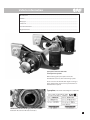
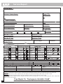
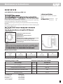
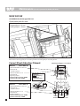
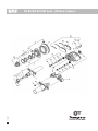
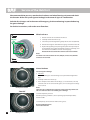
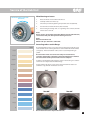
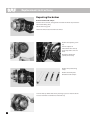
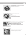
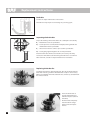
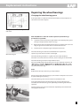
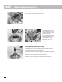
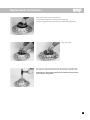
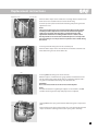
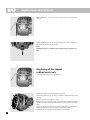
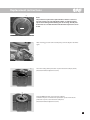
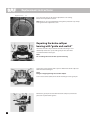
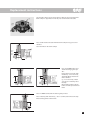
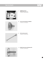
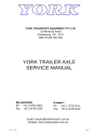
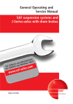
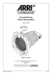
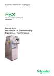
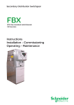
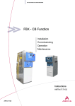
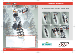
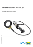
Maintenance and Repair Manual
for SAF Disc Brakes
SK RZ 9019 W with WABCO brake calliper
Edition 06/2009
Service
Vehicle information
Manufacturer..............................................................................................................................................................................
Address.........................................................................................................................................................................................
Body type.....................................................................................................................................................................................
Chassis no....................................................................................................................................................................................
Year of manufacture.................................................................................................................................................................
Registration date.......................................................................................................................................................................
Spare parts service for SAF axles
and suspension systems
When ordering spare parts quote correct axle
identification serial no., refer to the axle type plate.
Please enter the axle identification figures in the type
plates shown below so that correct specifications are
available when required.
Type plate (on the inside of the trailing arm or axle beam)
Identification of axles when type plate not available.
Production No. of axle on RH side of axle tube.
Information
Introduction
This manual is intended for vehicle operators and workshop service engineers for use with the SAF axles and suspension
units.
Always read the entire instructions before operating the trailer or proceeding maintenance and repair works. Failure to
comply with these instructions without written permission from SAF will void the axle or suspension warranty.
The maintenance schedules are recommended by SAF, but as operating conditions and milages dictate frequency in
servicing, a maintenance schedule to suit each individual operation must be established by the operator.
This manual does not cover all specifications manufactured by SAF. The information contained herein is general in
nature. The parts shown in the illustrations are representative, they can vary in some details to your axle/suspension
equipment.
Every precaution for accuracy has been taken in the preparation of this manual. However, SAF/Transport Specialties
Limited do not accept responsibility for any omissions or errors that may appear, neither do they accept legal liability for
any loss in connection with the information contained within this manual.
Personal Safety Precautions
Maintain workshop fitters safety precautions to avoid serious personal injury or loss of life. Only qualified staff are
permitted to install, operate, maintain or repair brakes, axles and suspension components.
Warning!
On all suspensions a system failure may occur, this can cause the trailer chassis or axle to drop violently down. It is
recommended that on air suspensions the system is completely deflated during repair works.
Before jacking up the axle or the trailer, check for solid ground, chock the wheels.
Always firmly secure the chassis and axles on strong support stands. This removes all imposed weight from the
suspension and ensures that any work required underneath the trailer is carried out in safety.
For the latest SAF information, updates and technical
bulletins, visit www.transpecs.co.nz
Contents
General service instructions for SAF axles and suspension units
Vehicle information......................................................................................................................................................................................... 1
Introduction....................................................................................................................................................................................................... 2
General operating instructions................................................................................................................................................................... 4
Service schedule............................................................................................................................................................................................... 5
Service report form.......................................................................................................................................................................................... 6
Maintenance instructions
Maintenance instructions for SAF axles
SK RZ 9019W – with WABCO Disc Brake type PAN 19-1...................................................................................................................... 7
Bolt / Nut torque values................................................................................................................................................................................. 8
Axle and suspension torque values........................................................................................................................................................... 9
Inspection for brake pad wear...................................................................................................................................................................10
Correct shock absorber fitment ...............................................................................................................................................................10
Brake testing (fault-finding flow chart)...................................................................................................................................................11
Spare part illustration and designation
SK RZ 9019W – with WABCO Disc Brake type PAN 19-1............................................................................................................ 12–13
Self adjuster check.........................................................................................................................................................................................14
Special notes....................................................................................................................................................................................................15
Servicing the hub unit.......................................................................................................................................................................... 16–17
Replacement instructions
Repairing the brakes............................................................................................................................................................................. 18–20
Repairing the wheel bearings............................................................................................................................................................ 21–23
Installing the hub unit with brake disc........................................................................................................................................... 24–25
Replacing of the tappet rubber boot seals................................................................................................................................... 26–28
Repairing the brake calliper bearing with “guide and seal kit”.............................................................................................. 28–31
Fitting the brake calliper..............................................................................................................................................................................31
Replacing the brake cylinder......................................................................................................................................................................31
Axle alignment................................................................................................................................................................................................32
Service Tools.....................................................................................................................................................................................................33
The item numbers indicated are given only for identification and to distinguish between different versions.
Use the part numbers from the valid spare parts documents for identification of spare parts.
SAF axles and suspension units are subject to continuous further development; the data and drawings contained in the
manual may therefore differ from the details given in the operating permit.
The contents of the manual do not constitute the basis for a legal claim.
Reprinting, reproduction or translation in whole or in part is not permitted.
The issue of this publication invalidates all earlier maintenance and repair manuals.
Note: We wish to think WABCO for providing various illustrations!
General operating instructions
for SAF axles and suspension units
1. Instructions and tips for vehicle operation
In order to maintain the operation and road safety of the vehicle, the maintenance operations prescribed by
SAF must be carried out regularly at the specified intervals
(see “Service instructions”).
Furthermore, ensure that
1.1 the disc brake is not overheated due to continuous braking action as irreparable damage to the
surrounding components – in particular the wheel bearings – cannot be ruled out. This can impair the
operational and road safety of the vehicle and represent a serious hazard for man and machine.
1.2 the compatibility of the brakes on the truck-trailer combination is checked. For reliable braking and
uniform brake lining wear, the brake systems of the two vehicles must be matched to each other.
1.3 the parking brake is not applied immediately when the brakes are hot as the resulting different stress
fields can damage the brake discs / drums.
1.4 the drum brakes are not overheated as this will result in a dangerous reduction in braking efficiency.
1.5 the maximum permissible axle loads and speeds are not exceeded.
1.6 the cargo is evenly distributed over the loading area and safely secured.
1.7 on vehicles with air suspension, the air bags are always fully inflated before moving the vehicle.
1.8 the prescribed wheel rims and tire sizes are employed.
1.9 The location and securing of the wheels is correctly maintained. Do not repaint the contact faces on
either the wheels or hubs. On the contact surface of the wheel the maximum permissible coating
thickness of 50 µm (primer plus paint) must not be exceeded.
All attachment faces must be clean with plain smooth surfaces free from any contamination of dirt, rust,
grease, excessive paint and damage. In general refer to the wheel manufacturers recommendations, or
consult your trailer builder for any wheel mounting details.
1.10 the tires are inflated to the prescribed inflation pressure.
1.11 your driving style is matched to the road and weather conditions.
1.12 chassis support legs are used when loading/unloading construction machinery.
1.13 the use of auxiliary trailer braking facilities (trailer underrun brake) is not permitted.
2. Vehicle safety
2.1 The daily check of the vehicle for road safety before moving the vehicle is the responsibility of the driver.
2.2 Modifications to the suspension and braking system are strictly forbidden.
2.3 Compliance with the specified permissible axle loads, observing the specifications in the vehicle
operating manual, vehicle inspection intervals and the regular maintenance intervals is the
responsibility of the vehicle owner.
2.4 We strongly recommend using only SAF approved replacement and spare parts which are covered
by SAF product liability. These products have been thoroughly tested by SAF for safety, functionality
and suitability. Usage of these parts guarantees not only safety on the roads but satisfies the legal
operational requirements. SAF is not in a position to judge whether those products from other
companies represent a safety risk for SAF axles and systems.
3. Warranty
Refer to Transpecs Warranty Handbook.
4. Service and spare parts
A close-knit service network of SAF partner companies is at your disposal for technical advice on SAF
axles and suspension systems as well as for supplying approved SAF spare parts .
In case of repair, we strongly recommend using only SAF original parts for those reasons
mentioned in point 2.4
SAF axles and suspension units are subject to continuous further development; the data and drawings
contained in the manual may therefore differ from the details given in the operating permit.
The contents of this manual does not constitute a basis for a legal claim. Reprinting, reproduction
or translation in whole or in part of this manual is not permitted. This manual supersedes all earlier
maintenance and repair manuals.
Service schedule
SAF Service Schedule - SKRS/RZ 9019W
These are minimum requirements, operators must implement a service schedule to suit their specific requirements
Service Schedule
Mileage intervals
>
After First
5,000km
or
Time intervals
>
Whichever occurs first
Periodic check
every
30000 km
every
120000 km
after first month
every
3 months
every
12 months
•
•
Comments
/
Mechanical check
Attention: Torque check wheel nuts after the first 50 km and 150 km (repeat
after every wheel removal). Follow a prescribed wheel nut torque
procedure.
Torque check all nuts and bolts to recommended setting
Intra/Modul Shock absorber bolts
400Nm
Intra/Modul Pivot bolts
1200Nm
All axles
Wheel nuts
600Nm
All axles
Hub nut
900Nm
Intra
Air spring mounting nuts
Modular
Air spring screws
Plastic base 20Nm
Steel base 80Nm
Plastic base 20Nm
Steel base 80Nm
Modular
U Bolts
580Nm
Modular
Air spring mounting plate
180Nm
Check wheel bearings for noise and play. Hub end-float adjustment not possible,
carry out hub service checks if required. Max axial play 2.5mm
•
•
•
•
•
•
•
•
•
•
•
•
•
•
•
•
•
•
•
Minimum Requirement
Pack wheel bearings with fresh grease after 500,000 km or 48 months,
whichever comes first. Check condition of taper roller bearings and
replace if necessary.
Remove hubcaps and check for lubricant leakage.
Check brake caliper for adjustment, remove pads and ensure slides are free.
Clean out dust and inspect all boots for holes.
Remove hub from spindle and add anti seize compound.
Check Truck and Trailer Compatability (Brake Balance) Max Lead 0.14bar
Visual and safety inspection
Components found to be worn down to their wear limits must be renewed
Inspect the brake caliper guide system. Check for free movement and sliding
action.
Brake caliper, inspect rubber boots for cracks and damage.
Check adjuster cap for correct seating.
Inspect the brake pad thickness at regular intervals (e.g. whenever tyre pressure
is checked) but at least every 3 months.
Inspect the brake disc for cracks.
Inspect suspension components for correct fastener connections, wear, leakage,
corrosion, distortion, damage.
Check hanger brackets, inspect the pivot bolts and shock absorber bolts with
recommended torque setting.
Inspect suspension for correct ride height setting, readjust if required.
General inspection
Check brake efficiency and application.
Check air springs for damage or cracks.
Ensure all ABS sensors fitted are aligned and cabling is in good condition.
Check for air leaks.
All air line connections are in good condition .
All piping is secured and no signs of chaffing.
Brake chamber blanking grommets are removed from the correct locations.
Shock absorbers fitted correctly.
•
•
•
•
•
•
•
•
•
•
•
•
•
•
•
•
•
•
•
•
•
•
•
•
•
•
•
•
•
•
•
•
•
•
Every Reline
Torque specifications:Refer SAF General Operating and Service Manual or visit www.transpecs.co.nz, choose technical to download PDF file.
Special service conditions
Vehicles with Aluminium Hangers or Steer Axles please refer to separate service instructions on these items
Vehicles with long standing periods:
service at specified time intervals
Vehicles used under extreme conditions:
shorten the service interval by 1/2
e.g. Forestry, construction site operation, multi-shift operation, offroad, regular river fording, construction site & multi shift operations.
Warranty claims will only be accepted as long as the operating and maintenance instructions have been complied with and only genuine SAF replacement spare parts have been used
5
Service Report
Complaint*: -
Customer / Contact Person* --
Report No.
Tel:* --
W
Transpecs Customer No Customer Order Number* ---
Date*
- /
Vehicle Manufacturer* -
Registration No*. --
Chassis No*.
Date of Registration*
Mileage* --
SAF axle type* -Disc / Drum*-Ride Height
Suspension type* INTRADISC / Modular / Mechanical / Other
st
Serial No. 1 Axle* -Serial No. 3
nd
Serial No. 2
nd
-
/2
Axle --
th
Axle --
Serial No. 4 Axle --
Garage/Repairer* -Contact: --
Date of Repair
Invoice No.
--
Tel*: ---
Tick approprite box*:
Vehicle type
Position on vehicle
Body type
Left Right Front “B”
Other
Rear B
LSV Yes
/ No
1
st
Axle
Tipper
Tanker
EBS: Yes
/ No
2
nd
Axle
Stock
Low Loader
ABS: Yes
/ No
3
nd
Axle
Flatdeck
4
th
Axle
Container
Tractor
Manufacturer:
Type: --Registration date:
Km: -Loaded Truck and Trailer compatibility completed: Yes
Date:
Carried out by (W/Shop): -Date:
Kms: -Trailer Last Service
Carried out by (W/Shop): -
Curtainsider
Tyre Size:
x
Single / Dual
EBS
No
Yes
No
Copy invoice encl: Yes / No
KMS --
-Copy invoice encl: Yes / No
Important:
Stage One: All items/boxes marked * must be completed in full and returned to Transpecs before any replacement parts can be dispatched.
Stage Two: Labour invoices with a completed copy of this Report, to be returned to Transpecs within 5 days of the date of repair.
Stage Three All replacement parts subject to this claim required by Transpecs must be returned to within 14 days.
Failure to submit all the required information and parts will result in an invoice being raised to cover costs of replacement parts, labour, transportation
and/or any other costs involved.
Fax Back To Transpecs 09-980-7348*
6
Return Completed form to Transpecs with invoices when repairs are completed
Maintenance instructions
SK RZ 9019 W
with WABCO Disc Brake type PAN 19-1
Hub unit inspection
Grease for repairs is contained in every repair kit.
48
of taper roller bearing and replace if necessary.
Do not dismantle the hub bearing assembly, unless carrying out a regreasing.
Inspect the Hub Unit at any brake disc replacement.
Check for excessive grease leakage and any abnormal noises whilst rotating
the hub.
When replacing brake pads inspect the rubber boot seals of the calliper guide
pins and the tappet seals.
Stub axle:
5 387 0015 06
5 387 0021 01
600g
1kg
or Hub Unit.
Tighten Hub Nut
900 Nm
On left-hand side in direction of travel:
Left-hand thread
On right-hand side in direction of travel:
Right-hand thread
Tightening torque to 900 Nm. Each hub unit must be rotated
smoothly at least twice while tightening the nut.
Marking of the nuts with left-hand thread: Milled groove on
outside of hexagon.
NOTE!
Worn brake linings or excessively worn brake discs result in a reduction in
Maximum wear limits
Brake Rotor
Brake Pad
Diameter
(mm)
„A”
new (mm)
„B”
max. wear limit (mm)
„C”
new (mm)
„E”
max. wear limit (mm)
370
45
37
30
11
Brake pads, use only original SAF spare parts for replacement.
Tightening torque in Nm
Bolt assembly’s
Attention! Bolts must not be oiled!
Pos.-No.
Brake chamber / spring brake chamber
2 hex. nuts M16x1.5
Guide pin bolts on brake calliper
Brake calliper mounting on axle M16x1.5x55
Pad retainer clamp
Assembly tools
Hub nut socket
Hub puller
Lever for hub cap
Tool box WABCO
SK RZ 9019 W
210
70
80
56
56.1
63.1
63.2
340 ± 20
290
30 ± 15
SAF Part No.
1 012 0024 00
4 434 3822 00
1 434 1041 00
3 434 3328 00
7
Bolt / Nut torque values
The following tightening torques are only valid if no other values are given in the axle maintenance chart.
Torque wrenches settings, impact wrench not permissible.
Thread
M8
W.A.F. 13
M8×1
M 10
W.A.F. 17 / 16
M 10 × 1
M 12
W.A.F. 19 / 18
M 12 × 15
M 14
W.A.F. 22 / 21
M 14 × 1.5
M 16
W.A.F. 24
M 16 × 1.5
M 18
W.A.F. 27
M 18 × 1.5
M 20
W.A.F. 30
M 20 x 1.5
M 22
W.A.F. 32
M 22 × 1.5
M 24
W.A.F. 36
M 24 × 2
M 27
W.A.F. 41
M 27 × 2
M 30
W.A.F. 46
M 30 × 2
M 36 × 2
W.A.F. 55
Wheel fixing:
Wheels see appropriate axle maintenance chart.
Material
8.8
10.9
12.9
25
35
41
27
38
45
49
69
83
52
73
88
86
120
145
90
125
150
135
190
230
150
210
250
210
300
355
225
315
380
300
405
485
325
460
550
410
580
690
460
640
770
550
780
930
610
860
1050
710
1000
1200
780
1100
1300
1050
1500
1800
1150
1600
1950
1450
2000
2400
1600
2250
2700
2450
3450
4150
Axle & Suspension Torque Values
Axle SK RS / RZ 9019
Hub Nut
L/H side direction of travel - L/H thread - Grooved hub nut and Spindle
R/H side direction of travel - R/H thread - Axle serial number on spindle
200 Nm + 15 Deg
In service hub not torque check whilst rotating the hub twice
900 Nm
Brake Caliper mounting bolt M16
290 Nm
Guide/Slide Pin bolts M16
290 Nm
Wheel Nuts M22
600 Nm
Modular Suspension
Pivot Clamping Bolt Assy M30
Pretighten to 400 Nm +
Final tightening torque
400 Nm
+
120º
Shock Absorber Nuts M24
400 Nm
U/Bolts for Trailing Arms M22 (Diagonally in three Stages)
650 Nm
Air Spring Mounting Plate M20
180 Nm
Air Spring Upper Nut M12
40 Nm
Air Spring Self Tapping Bolt (Plastic Plunger Piston)
20 Nm
Air Spring Bolt (Steel Plunger Piston)
80 Nm
lntradisc Dual
Pivot Clamping Bolt Assy M30
Pretighten to 400 Nm
400 Nm
Final tightening torque
120º
In service checking torque
Shock Absorber Nuts M20
1200 Nm
Nut Contact Surface Dry
600 Nm
Aluminium Hanger Brackets
Pivot eye bolt
Inspection torque
1200 Nm
Shock absorber bolt
Inspection torque
600 Nm
Air Spring Top Nut M12
Air Spring Plunger Bolts M16
40 Nm
Plastic Plunger Piston
Steel Plunger Piston
80 Nm
180 Nm
9
Maintenance (Visual inspection for brake pad wear)
SK RZ 9019 W
with WABCO Disc Brake type PAN 19-1
Check brake pads for wear
Wear limit
Long guide pin > 97 mm
Short guide pin > 70 mm
shockabsorber fitment.pdf
08/04/2006
13:49:53
shockabsorber fitment.pdf
08/04/2006
13:49:53
Check wear limit of brake pads and brake disc replace if necessary.
When distance on long guide pin is exceeding 97 mm or on short guide pin exceeding 70 mm.
90
Correct Shock Absorber Fitment
Bolt Kit 78 / crossmember
Steel hanger bracket
90
3 341 2803 10
78
Collared bolt M20×1.5×120 -10.9
4 343 2803 10
- dacromet coatedCollared nut M20×1.5 - 10
4 247 4044 10
Tightening torque:
Contact surfaces greased: 500Nm
Contact surfaces dry: 600Nm
C
M
Y
C
CM
M
MY
Y
CY
Attention:
TOP mark facing
upwards in
working position
CM
CMY
n
itio
MY
K
CY
Bolt Kit 3 341 2802 10
CMY
Collared nut M20×1.5 - 10
4 247 4044 10
Tightening torque:
Contact surfaces greased: 500Nm
Contact surfaces dry: 600Nm
10
P
TO
s
Po
TOP
K
Collared bolt M20×1.5×150 -10.9
4 343 2802 10
- dacromet coated-
Axle
Centre
Wheel side
Wheel side
TOP
68
68
Functional suspension arm
Axle
Centre
brake testing fault finding procPage 1
25/06/2006
15:06:29
Maintenance instructions
Brake test
Fault-finding chart
Disc brake
Lift vehicle,
turn wheel
by hand
Does wheel
turn freely?
NO
Residual pressure
in brake cylinder?
NO
C
YES
Running
clearence OK?
YES
NO
YES
M
Check upline
brake devices
and replace,
if necessary
Running
clearence OK?
Y
CM
NO
YES
MY
END
Check adjuster
END
Uneven brake
pad wear? 1)
NO
YES
END
CY
CMY
Check brake
calliper bushings
and repair,
if necessary
Adjuster OK?
K
NO
YES
END
Brake calliper
guide system OK?
NO
YES
Binding not
due to disc brake
Replace brake
calliper
END
END
Check brake
calliper bearings
and repair,
if necessary
END
1)
Difference between wear of inboard and outboard pad, and diagonal wear ≤ 5 mm.
11
SV11368MS
SK RS/RZ 9019W Axle - (Wabco Caliper)
12
SK RS/RZ 9019W Axle - (Wabco Caliper)
Item
19
20
22
22.1
27
27
27.2
27.3
29
29
29
31
34
34
38
38.1
39
40
40
41
56
56.1
59
60
64
70
76
76.2
78
Part Number
4 315 0052 00
4 315 0056 00
1 011 0070 00
1 011 0071 00
3 307 3026 00
3 307 3033 00
3 434 3012 00
5 387 0011 05
4 079 0004 00
4 079 0014 00
4 079 0012 00
1 303 1075 11
1 303 1112 10
1 095 1057 00
1 303 1125 10
24738/ISO
B5781/32
4 373 0043 01
4 373 0044 01
3 434 3014 01
4 315 0054 00
3 304 0092 00
3 304 0092 20
1 094 0037 00
4 337 2026 00
4 343 2914 10
4 375 1004 10
3 080 0032 00
3 080 0033 00
3 057 0080 00
3 434 3827 01
4 189 0051 00
4 343 2067 00
4 029 1042 00
Qty
2
2
1
1
2
2
2
2
2
2
2
16/20
16/20
16/20
16/20
16/20
16/20
2
2
2
2
2
2
1
2
10
2
1
1
1
2
2
4
2
PWI
1 012 0024 00
4 434 3822 00
3/434/3328/00
5/387/0021/01
3/434/3327/00
1
1
1
1
1
1
Description
Axle Nut Lock Oring
Axle Spindle Oring
R/H Axle Nut M120x2/SW140
L/H Axle Nut M120x2/SW140
Hub and Bearing Assy Dual Alloy Wheels
Hub and Bearing Assy Dual Alloy Wheels
Bearing and Seal Kit
Hub Grease Pack
Disc Brake Rotor 22mm Hole
Disc Brake Rotor 27mm Hole
Disc Brake Rotor
Wheel Bolt
Wheel Bolt 112mm
Wheel Bolt Spacer (used with 1 303 1112 10 stud)
Wheel Bolt 112mm (stepped shoulder)
Wheel Nut
Wheel Nut Dual Alloy (Sleeved)
Inner Hub Seal
Outer hub Seal
Hub Seal Kit
Hub Cap Oring
Hub Cap
Chrome Hub Cap
Hubo Mount Washer
Protection Plug
Caliper Mount Bolt M16
Caliper Mount Bolt
R/H WABCO Brake Caliper
L/H WABCO Brake Caliper
Brake Pad Set
Tappet and Guide Pin kit
ABS Sensor Mount Bracket
ABS Sensor Mount Screw
ABS Sensor
Notes / Alt no.
8 stud 275PCD
10 stud 285PCD
Sleeved nut - 8 stud 275PCD
8 stud 275PCD
10 stud 285PCD
(20, 27.3, 38, 38.1)
PAN19-1RH
PAN19-1LH
12/999/737
12/999/738 (65,66,70,80)
441 032 579 0
Tools
Pad Wear Indicator
Hub Nut Socket
Wheel and Hub Puller
Wabco Caliper Tool Kit
SAF Fitting Paste - 1kg Tube
SAF Calliper Adjuster Tool
13
Maintenance instructions
Self-Adjuster check
Remove adjusting screw cap.
Caution!
Do not overload or damage the hexagon drive (8 mm) of the adjusting
screw. Do not use an open-ended spanner.
Turn the adjusting screw clockwise using an 8 mm ring spanner.
Actuate the brakes 5 times (approx. 1 bar)
When the self-adjuster is functioning correctly the ring spanner must turn
anti-clockwise.
Caution!
Ensure that there is sufficient room for the ring spanner to rotate
freely during adjustment.
Keep your hands off from the spanner whilst actuating the brakes.
Danger for serious personal injury.
Note:
As the number of rotation steps of the ring spanner increases, the turn
angle or movement of the ring spanner must reduce.
If the spanner rotates as described above, the self-adjuster is functioning
correctly.
If the following faults occur:
The adjusting screw or ring spanner
a) does not turn,
b) turns only with the first application of the brakes,
c) turns forward and then back again at each application of the brakes,
the self-adjuster is not functioning correctly and the brake calliper has to
be replaced.
Remove the ring spanner.
Coat the adjusting screw cap with grease in the snap-fit area, then push on
the cap and ensure that it is firmely seal tight fitted.
Inspect condition of adjusting screw cap for proper seal function to avoid
water entry into the self-adjusting gear.
Replace adjusting screw cap if found worn or damaged.
14
Maintenance instructions
Special notes
BRAKE BALANCE
To obtain maximum performance from the disc-brakes, brake
balance between the truck and trailer must be carried out
before going into service and again at 5000km service, and
then every 12 months thereafter.
Maximum lead to trailer must not exceed 0.14 bar (2 psi).
Ensure that brake chamber plugs are removed from the bottom most drain holes.
Brake calipers are not covered by warranty for ingress of water or corrosion.
INSTALLATION REQUIREMENTS
FOR WARRANTY VALIDATION AND
MAXIMUM CORROSION RESISTANCE,
PLUG TOP & SIDE
HOLES ONLY!
REMOVE PLUG FROM BOTTOM
MOST DRAIN VENT HOLES
installation requirements label.1 1
08/10/2006 15:29:22
Only brake cylinders approved by the brake
or axle manufacturer may by used.
Ensure the drainage holes are correctly located.
Painting instructions
During painting work, all rubber parts must be covered as otherwise the rubber will become brittle and
thus be damaged.
15
lour.pdf
07/05/2006
Service of the Hub Unit
11:55:41
We recommend that you carry out the wheel rock test and wheel bearing noise test and check
the function of the seal system (grease leakage) in the event of signs of a malfunction.
At brake disc changes and in the event of damage, e.g. brake overheating, inspect the bearing
for grease leakage.
For further instructions, refer to the error flow chart.
Wheel rock test
Pull
Press
1. Raise the wheel. Do not remove the wheel!
Dial gauge
2. Carefully remove the wheel cap.
3. Check the prescribed tightening torque of the axle nut (900 Nm).
4. Position the magnetic foot of the dial gauge as shown on the left.
5. By alternately pulling and pressing (first pull at the top and press
at the bottom, then pull at the bottom and press at the top), rock
the wheel and read off the travel on the dial gauge.
Rotate the wheel several times before each measurement!
Note!
If a wheel rock of more than 0.25 mm (250 µm) is measured, the hub
unit has to be serviced.
Press
Pull
Example illustration
“OK”
Grease leak test
Increased grease leakage
1. Indicator:
If the wheel flange is covered with grease up to half the height when
“dry”.
2. Carefully remove the wheel cap.
3. If the complete inside of the wheel flange, i.e. inside of cover, axle nut,
axle tube and seal are covered with grease, an increased grease leakage
has occurred.
Example illustration
“Not OK”
Note!
There may be a small amount of grease on the lower edge of the seal.
This is normal and does not indicate grease leakage.
Seal not completely covered.
Normal operating condition (= after a prolonged period of operation).
Hub unit is OK.
Seal completely covered all over with tar-like grease.
Recommended measure:
Service the hub unit
16
Example illustration
rature guPage 1
Service of the Hub Unit
Wheel bearing noise test
Turn the wheel backwards and forwards
26/06/2006
20:18:46
(fast and slow)
1. Raise the wheel. Do not remove the wheel!
2. Carefully remove the wheel cap.
3. Check the prescribed tightening torque of the axle nut (900 Nm).
4. Turn the wheel in both directions (fast and slow).
5. If the bearing feels rough and / or a “grinding” noise is heard, the hub
unit has to be serviced.
Note!
Noises can also be caused by the brakes. Before removing the hub unit,
remove the brake pads and repeat the bearing noise test.
Note!
Measure the wheel rock.
Wheel rock up to 0.25 mm is admissible.
Annealing colours on the flange
Annealing
temperature ºC
Pale yellow
200
Straw yellow
220
Golden yellow
230
Yellowish brown
240
Terra-cotta
250
Red
260
Purple
270
Violet
280
Dark blue
290
The discolouration is to be seen at the contact points to the brake disc and
at the chamfer to the centring diameter or at the bottom of the blind holes
(see figures). This discolouration is blue, red or occasionally tending to
yellow.
Discolouration in this area can be caused by incorrect function/
operation of the brakes. The brake system must therefore be checked
for tractor/trailer brake synchronisation and for adaption.
It must be assumed that particularly the grease or the bearing race and the
seal have been subjected to thermal damage.
If large amounts of grease escape at the same time from the outer seal
(under the cap), the hub unit must be serviced.
“OK”
“Not OK”
Cornflower blue
Pale blue
320
Bluish grey
340
Grey
“Not OK”
300
360
Recommended measure: Replace the hub unit.
17
Replacement instructions
Repairing the brakes
Removal of the brake calliper.
Park the vehicle on level, solid ground and chock the wheels to prevent the
vehicle from rolling away.
Lift the axle using a jack.
Loosen the wheel nuts and remove the wheel.
Remove the adjusting screw
cap.
Turn the adjuster in
anticlockwise direction up
to the stop until it clicks 2–3
times.
Unbolt the diaphragm
cylinder, if necessary.
Remove the pad retaining
clamp.
Remove the brake pads.
Unbolt the brake calliper.
Lever the hub cap off the hub unit by inserting a tyre lever into one of the
recesses around the circumference of the hub cap.
18
Replacement instructions
Press the ABS sensor completely out of the sensor mounting block and
place inside the axle tube.
The sensor holder can remain on the axle nut.
Loosen the axle nut and unscrew from the stub axle.
Axle nut wrench: SAF Part No. 1 012 0024 00.
Note:
Axle nut: W.A.F. 140
On left-hand side of vehicle
(as seen in direction of forward travel) – left-hand thread.
Identification of axle nut with left-hand thread:
Milled groove on outside of hexagonal head.
The complete hub unit with brake disc can be easily pulled off the stub axle.
If the bearing inner races tilt on the stub shaft, the hub unit can be pulled
off using a normal workshop puller or SAF Part No. 4 434 3822 00.
Note:
Do not disassemble the hub unit bearing assembly!
The wheel bearings have a long-life grease packing.
Grease change intervals, see chapter “Maintenance instructions”.
Adjustment screw
Pressure plate
Check the brake calliper for free movement, and sliding action.
Back off the tappets on the adjuster until the boots are visible.
Perform a visual inspection of the boots and all seals.
Screw in the tappets again completely.
19
Replacement instructions
Brake disc
See table in chapter “Maintenance instructions”.
The brake disc may only be cleaned using a dry cleaning agent.
A1
Inspecting the brake disc
B1
Inspect the braking surface of the brake disc carefully for serviceability.
A1 – Network-like cracks are permissible.
B1 – Cracks up to max. 1.5 mm (width and depth) running towards the
middle of the hub are permissible.
C1 – Unevenness in the disc surface up to 1.5 mm is permissible.
D1
C1
D1 – Cracks going right through the disc are not permissible.
Check the brake disc thickness and machine, if necessary. For safety
reasons, the limit thickness for machining the brake discs is 39–40 mm.
Max. wear limit, see table in chapter “Maintenance instructions”.
Replacing the brake disc
To remove the brake disc from the hub unit, drive all the wheel bolts out
of the hub unit using a hammer. Removal of the circlips is not necessary.
Before reassembling wheel hub and brake disc, remove any corrosion from
the contact surfaces.
Insert the wheel bolts at
an angle from below and
hammer into place (observe
twist lock).
Draw the bolts completely
into the hub unit using a
wheel nut and an impact
wrench.
20
Replacement instructions
Repairing the wheel bearings
Changing the wheel bearing grease
As the operations are identical for both procedures, the descriptions are
contained in the same chapter.
Arrangement of wheel bearing assembly
with seals
After 500,000 km or after 48 months’ operation, the following 3
procedures are possible:
Wheel bearing kit
1)
Inspection of the wheel bearing for further serviceability with grease
change and replacement of the seal rings.
2)
Replacement of the complete wheel bearing assembly with seals and
long-life grease. The wheel hub can continue to be used.
3)
Installation of a complete original compact wheel hub.
The wheel bearing has to be disassembled for the inspections;
replace any parts which are worn or damaged.
The wheel bearings must be in a good and serviceable condition.
The outer races must still have a correct, secure seating in the wheel hub.
The wheel bearing must turn freely without noises.
During assembly of the wheel bearing set, ensure absolute cleanliness of
life of the wheel bearings.
Note:
Replacement of only one bearing is not permitted.
Always change the wheel bearings in pairs with the complete seal set and
the prescribed grease packing.
Original compact hub
The wheel bearing axial clearance must not exceed 0.25 mm.
If the permissible limit for the wheel bearing clearance of 0.25 mm is
exceeded, the wheel bearing set or optionally, the bearing hub must be
replaced.
Checking of the axial clearance should be expediently carried out when
changing the brake disc.
21
Replacement instructions
Removing the wheel bearing assembly
Lever out the retaining ring using a screwdriver.
Place a drift against the joint
of the two wheel bearings and
drive the bearing inner races
out of the wheel hub together
with the seal rings.
Drive the bearing outer races
out of the hub housing using a
normal workshop drift.
Thoroughly clean the hub
housing.
Installing the wheel bearing assembly
Drive both bearing outer races into the hub housing until they bottom.
Use installation tool, SAF Part No. 3 434 1043 00.
Pack the space between the bearing outer race and shoulder with long-life
grease.
Coat the taper roller bearing with the remaining grease.
Distribute the grease supplied in the repair kit uniformly over both
bearings and use up completely.
22
Replacement instructions
Place the bearing inner races into the hub.
Secure both bearing inner races with the retaining ring.
Pack the ring gap on the face side of the bearing with long-life grease.
Fit the seal rings.
Press the seal rings into the hub on both sides using the installation tool,
SAF Part No. 3 434 1043 00, until they are flush with the edge of the hub.
If the hubs are subsequently painted, ensure that the contact surface
for the wheel is not painted.
23
Replacement instructions
Installing the Hub Unit with brake disc
Completely coat the wheel bearing seats on the stub shaft and in the Hub
Unit with SAF fitting paste (SAF Part No. 5 387 0015 06).
See chapter “Maintenance instructions” for recommended media.
Replace the rear O-ring on the stub shaft.
Inspect the O-ring on the axle nut and replace, if necessary.
900 Nm
Push the Hub Unit brake disc assembly onto the stub axle.
Screw on the axle nut.
Axle nut W.A.F. 140:
On LH side of vehicle (as seen in direction of forward travel)
– LH thread.
Identification of axle nut with LH thread: Milled groove on outside of
hexagonal head.
Tighten the axle nut.
Axle nut wrench: SAF Part No. 1 012 0024 00
Pre-tighten the axle nut to 900Nm whilst rotating the hub at least twice.
Loosen the axle nut again and repeat procedure.
Completely coat the ABS sensor with copper paste and install in the sensor
holder.
Inspect the O-ring on the Hub Unit for the snap fastening of the hub cap;
replace, if necessary. Push on the hub cap and check that it is securely
seated.
Remove the plug from the hub cap and push the ABS sensor until it is
contacting the exciter ring. Insert the plug into the hub cap again.
Measure the voltage output on the ABS sensor cable using a voltmeter
(approx. 100mV) whilst rotating the hub.
24
Replacement instructions
Pressure plate
Adjustment screw
Move the brake calliper so far so that there is enough distance between the
brake disc on the actuation side to insert the brake lining.
Insert the pressure plate into the brake mounting and push it against the
adjustment screw.
Note!
The pressure plate must seat correctly in the brake mounting guide
and the pin of the adjustment screw must be seated in the groove
of the pressure plate, otherwise the correct functioning of the
adjustment mechanism is endangered! Provision is made so that
the adjustment screw can be turned until the pin sits correctly in the
pressure plate groove. The protection cap must not be rotated during
this action.
64.1
Inserting new brake linings 64.1 on the actuation pad.
Move the brake calliper in the direction of the rim until the actuation side
of the brake lining 64.1 sits on the brake disc.
64.1
Inserting new brake linings 64.1 on the rim side.
With the help of a 1 mm thick feeler gauge (arrow) inserted between the
rim side of the lining and the brake calliper, regulate the adjuster with a
ring spanner until both brake linings sit on the brake disc.
Attention!
Do not use excessive force on the corners of the adjuster.
Note!
Direction of rotation in regulating the adjuster is anti-clockwise. Do not
assemble the lining retainer hoop until play has been adjusted.
64.2/64.1
63.1
Setting new retainer springs 64.2 onto the brake linings 64.1 and pressure
plate.
Push and depress the lining retainer hoop 63.1 in the opening of the brake
calliper so that the radial lugs of the retainer spring seat in the hoop.
25
Replacement instructions
Affixing new hex. screw 63.2 with 30±15 using a spanner onto the brake
calliper.
63.2
Push the new plug 65 into the opening of the brake calliper! Check the
wheel hub for freedom of movement.
Note!
Check the brakes on a rolling road test station after completion of
work.
65
Replacing of the tappet
rubber boot seals
Dismantle brake linings and pressure plate.
Move brake calliper by hand towards the cylinder.
Pull out the protection cap 66 using a screwdriver from the brake calliper
seating.
Check the thread on the adjuster screw.
Note! Lay the rim side brake lining in the lining cavity so that the adjuster
cannot be screwed out of adjustment. After checking remove the linings
again.
Secure the adjuster screw against turning (arrow) and screw out approx.
30mm anti-clockwise using a ring spanner on the hexagonals.
During this time check the thread for damage or corrosion.
26
Replacement instructions
66
Note!
The protection cap 66 can be replaced if dirt or water is seen to be
present over the seal seat of the brake calliper, or if the protection
cap has been damaged immediately prior to servicing. Should parts
be found to be corroded then the brake should be replaced in case of
doubt.
After checking, grease the thread and partly screw the adjuster clockwise
again.
66
Clean the seating of the protection cap 66 in the brake calliper (arrow)
(illustration without adjustment screw).
66
Push the new protection cap 66 over the adjuster.
Centralize the press-in tool over the protection cap 66 and insert the
protection cap in its seat in the brake calliper 59.
(illustration without adjustment screw)
27
Replacement instructions
Adjustment screw
66
Insert the protection cap 66 into the adjustment screw seating.
Grease the rim lip before insertion.
Note! Ensure an even and unwrinkled seating of the protection cap’s rim lip
in the groove of the adjustment screw.
Repairing the brake calliper
bearing with “guide and seal kit”
Dismantle the brake calliper 59 from the brake mounting 61 and
additionally remove the cap 83 of the guide pin 70.1/80.2 with a
screwdriver from the housing 59.
Note!
Do not damage the holes for the cap in the housing.
Loosen the screws 70.6/80.1 with a spanner. Remove the brake calliper 59
from the brake mounting 61.
Note!
Danger of trapping through loose brake calliper!
Clean contact surface (flush) on the brake mounting 61 to the guide pin.
Remove the guide pin 70.1/80.2 from the brake calliper 59, remove the
protection cap 80 from the groove.
28
Replacement instructions
21:06:04
page 21-04.pdf
25/06/2006
21:07:16
21:08:25
Lay the brake calliper 59 on a firm surface so that the cover opening of the
brake calliper is uppermost in order to press out the bushes 70.3/80.3.
Press out the bushes 70.3/80.3 from the brake calliper using a press and
mandrel.
F
Clean the holes in the brake calliper.
70.3/
80.3
70.3/
80.3
59
F
F
C
M
Y
CM
MY
L2
L1
CY
CMY
K
B
A
Press in two new bushes 70.3
and for the longer guide pin
70.1:
Firstly (A) the inner bush with
mandrel (L1 = 52.2 ± 0.2 mm),
and finally (B) the outer bush
with a mandrel
(L2 = 13.2 ± 0.2 mm), in both
cases press in until they meet
the stop.
Grease sliding surfaces of the
bushes and the space between
them.
Press in a new bush 80.3 for the shorter guide pin 80.2.
F
Press in bush (C) with mandrel (L3 = 38.7 ± 0.2 mm) until it meets the stop.
Grease sliding surfaces of the bush.
L3
C
29
Replacement instructions
Insert the new protection cap 80 in the seat (arrow) of the brake calliper
(59).
21:27:13
Note! Clean seating before insertion. For ease of insertion of the protection
cap it is recommended to lightly grease the rim lip.
59
80
21:28:03
Note! Ensure an even and unwrinkled seating of the protection cap’s
rim lip in the groove of the brake calliper.
Grease the running surfaces for the guide pins 70.1/80.2 and the rim lip of
the protection cap 80.
70.1/80.2
Insert the new guide pins from the direction of the cylinder into the brake
calliper 59 and push the protection cap 80 against the seating of the guide
pins 70.1/80.2.
Lightly move the guide pins backwards and forwards several times as
illustrated in the sketch.
The longer guide pin 70.1 is the shoulder bolt and is fitted on the
brake disc run in side. The shorter guide pin 80.2 is the play bolt and is
fitted on the brake disc run out side.
80
Remove excessive grease. The flat surfaces of the guide pins to the
brake mounting (arrow) must be free of grease!
70.6
Seat the brake calliper 59 onto the brake mounting 61 and insert the fitted
guide pins 70.1/80.2 flush.
80.1
70.1
80.2
Fit the new screws 70.6 (long for the shoulder bolt 70.1), 80.1 (short for the
play bolt 80.2) through the previously fitted guide pins in the brake calliper
59 and screw the brake calliper to the brake mounting 61.
Tightening sequence: 1st screw 70.6 / 2nd screw 80.1
80
Note!
It must be ensured during tightening of the screws when assembling
that the protection cap 80 is not damaged or rotated. First, screw
tightly the slide fit longer guide pin 70.1 and then screw tightly the
running fit shorter guide pin 80.2.
Should the guide pins 70.1/80.2 be loosened during maintenance
work from the brake mounting 61, then these must be replaced with
new screws 70.6/80.1 when re-assembling.
80.2
Move the brake calliper several times backwards and forwards over the
guide pins 70.1/80.2. Ensure ease of movement.
Note!
Do not squash the guide pins against the brake mounting!
70.1
30
Replacement instructions
Grease the holes for the cover plate 83 in the brake calliper 59.
21:52:11
F
F
83
Insert the new cover plate 83 into the holes of the brake calliper 59 and
press home using a suitable tool.
83
59
59
Note!
Avoid damaging the cover.
80
Fitting the brake calliper
Seat the brakes with brake mounting over the brake disc and fit to the axle.
Tightening sequence of the screws:
RH side clockwise
LH side anti-clockwise
Each time begin the sequence with the shoulder bolt (if applicable).
Position of shoulder bolt: In the direction of wheel rotation – the run out
side of the outer corner of the flange.
Replacing the brake cylinder
Before fitting the brake cylinder clean the sealing surface of the brake
calliper and grease the bearing on the brake lever (arrow).
Set the brake cylinder onto the brake calliper and screw the nuts tightly
with a spanner - torque to 210 Nm.
Note!
According to the respective fitting position, the lower drain holes on
the bottom of the cylinder must be clear.
31
Axle alignment
For axle alignment, the air suspension must be adjusted to the ride height specified by SAF.
Semi-trailers with self steering axle
Distance A, B, C max. permissible deviation 1.0 mm
Toe setting ± 12’ = ± 3.0 mm/m Camber ± 12’
Values apply to unloaded vehicle.
Air suspension must be in Ride Height for axle alignment check and re-adjustment works.
In the case of self steering axles the stabilizing chambers must be pressurised to 2.0 bar.
Total toe-in 4.0 mm/m.
Trailer
Distance A, B, C max. permissible deviation 1.0 mm
Toe setting ± 12’ = ± 3.0 mm/m Camber ± 12’
Values apply to unloaded vehicle.
Air suspension must be in Ride Height for axle alignment check and re-adjustment works.
The max. permissible deviation values for axle aligment are according to the tyre manufacture specifications.
To avoid excessive tyre wear we recommend having the alignment checked at regular intervals.
Deviations may be caused by:
• loose U-bolts
• spring guide bearing wear
• deformation of axle assembly components due to improper use
The relevant reference point for alignment is the hub cap centre or stub axle centre.
32
Service tools
1. WABCO tool box
Wabco Part No. 12/851/021
SAF Part No. 3/434/3328/00
2. Axle nut wrench W.A.F 140mm
SAF Part No. 1 012 0024 00
3. SAF ratchet wrench
SAF Part No. 3 434 3327 00
4. Wheel bearing installation drift
SAF Part No. 3 434 1043 00
33
Transport Specialties Limited
P O Box 98-971 S.A.M.C., Cnr Kerrs Rd, Wiri, Auckland
Phone: (09) 980-7300, Fax: (09) 980-7306, Parts Fax: (09) 980-7341
Email: [email protected], Website: www.transpecs.co.nz
RGSMR9019W-0806