1
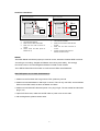
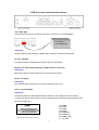
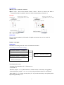
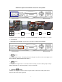
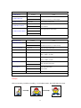
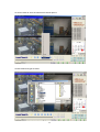
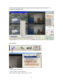
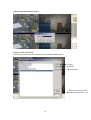
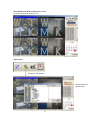
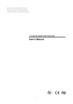
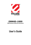
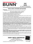
DVR System User Guide
Video:
1) Camera Connection
DC
LEVEL
Connect the camera to the CAMERA INPUT
V.P
CH1
CH2
CH3
VIDEO
CH4
DC
MONITOR
on the Rear Panel of the DVR.
CH1
CH2
CH3
CH4
VIDEO
LENS
AC24V/DC12
Rear part of CAMERA
2) Monitor Connection (Composite Connection Method)
Connect the monitor to the MONITOR OUT on
the Rear Panel of the DVR. (BNC or S-Video Type)
- VGA output is optional.
CH1
CH2
CH3
CH4
CH1
CH2
CH3
CH4
MONITOR
VIDEO A
IN
OUT
3) NTSC and PAL system detect.
Power on camera first, then power on DVR.
DVR system detect default is AUTO. DVR would detect NTSC or PAL system automatically.
- But if by order, factory can set to NTSC or PAL on request.
When you find the DVR detect wrong system, please follow the procedure.
Correct:
Camera (PAL) (power off) + DVR (Power off): Power on Camera (PAL) ÆPower on DVR
(System detect = PAL)
Wrong:
Camera (PAL) (power off) + DVR (Power off): Power on DVR (does not know what (NTSC or
PAL) system on it now) ÆPower on Camera (DVR System detect = nothing)
For example:
DVR NTSC but Camera PAL, it shows like a green line. Solution? Reboot DVR, DVR would
detect system again.
Notice: NTSC / PAL is switch able on system setup menu.
Check Main MENUÆSystem SetupÆ VIDEO INPUT: NTSC / PAL system detection.
- AUTO / NTSC / PAL.
1
Hard Disk installation:
1
How to connect single HDD
2
I/O BOARD
1
How to connect 2 HDD
I/O BOARD
2
1
1
MASTER
tie
2
2
MAIN BOARD
HDD1
3
MASTER
MAIN BOARD
HDD
SLAVE
HDD2
Set the drive jumpers as specified by hard disk drive manufacturer.
Set the drive jumpers as specified by hard disk drive manufacturer.
One hard disk installed.
1.
Two hard disk installed.
2.
Make sure the HDD is MASTER.
2.
Make sure the HDD is MASTER and
3.
Make sure the cable connector is
1.
SLAVE.
3.
correct.
4.
Make sure the cable connector is
correct.
Please check the HDD panel for
4.
Master set up.
Please check the HDD panel for
Master and Slave set up.
Notice:
-Hard Disk Master and Slave jumper pin must be correct, otherwise it makes DVR work fault.
-According to our testing, Seagate and Maxtor are working more stably . We strongly
recommend user to choose Seagate and Maxtor instead of other brands.
-Go to MENUÆHard Disk Information to make sure all HDDs are all detected.
After DVR power on, No hard disk detected?
1. Make sure the first hard disk is a good one. Else, please try second.
2. Make sure hard disk Master or Slave pin is correct. There is only one HDD, set it as Master.
With two hard disk install, set them as Master and Slave.
3. Make sure hard disk IDE cable and power core, plug in tight. The removable hard disk also
plug in, too,
4. Open DVR front case, make sure all IDE cable or power core are not relax.
5. Still nothing detect, please contact sales.
2
DVR rear panel connector description:
OUT - BNC Type:
Video looping out can be connecting to another 4 CH DVR or a 4 CH Multiplexer.
A 4 CH DVR or
a 4 CH Multiplexer.
Advantage:
Double image recording backup, capable data to retrieve if unsafe events happen.
75 ohm - DIP type:
For video looping out impedance terminator. High and Low switch.
Monitor out – BNC and S-Video type. (VGA interface is optional.)
Advantage:
Multi users view live image, keep living environment more safety.
Audio – RCA type:
Advantage:
One channel audio input and out, to record important events voice.
Alarm – 25-pin DB type:
Advantage:
Connect the Sensor to the SENSOR INPUT/ OUTPUT on the Rear Panel of the system.
It could be an alarm-warning bell or an alarm warning light to remind the security guard, while
an event is happening.
1.ALARM0
2.ALARM1
3.ALARM2
4.ALARM3
23.ALARM NC
24.ALARM NO
25.ALARM COM
5. ~ 19. GND
13,12,11,10,9,8,7,6,5,4,3,2,1
25,24,23,22,21,20,19,18,17,16,15,14
3
Connecting:
Relay output : COM+NC, COM+NO
Alarm input : Short-circuit between Alarm0, Alarm1, Alarm2 or Alarm3 and GND is
recognized as alarm by default. Alarm0~3 will be corresponding to Camera1~4.
Example:
ISP – 9-pin DB type:
Advantage:
Easy for firmware update by ISP transfer if supplier recommend user, a new version is
available now.
RS 485 – Jack type:
Advantage:
Multi DVR connecting and user control. RS 458 cable included
For example, A business building:
5F. Peripheral: Cameras x 4; 4 CH DVR x 1
4F. Peripheral: Cameras x 4; 4 CH DVR x 1
3F. Peripheral: Cameras x 4; 4 CH DVR x 1
RS 485 + /- all connect correct.
2F. Peripheral: Cameras x 4; 4 CH DVR x 1
1F. Peripheral: Cameras x 4; 4 CH DVR x 1;
Monitors; Control keyboard.
Total Peripheral amount:
-Cameras (Fixed cameras or P / T /Z dome) x 20.
-4 CH DVR x 5
-Monitors: maybe x 1 or 5. (Video switcher or a Matrix device is necessary on suggestion.)
-Control Keyboard: maybe x 1 or x 4 or x 8. According to different system or multi guards.
-Each DVR or P / T / Z dome in every floor (1F ~ 5F) can be control by a user (users) with a
keyboard (keyboards) in 1 F.
4
DVR front panel touch button function description:
1
2
3
4
2
1
3
4
>Playback mode, press 4 quad key. 4 or 9 split screen display. On 9 split screen, 1 ~ 4 is live,
6 ~ 9 is playback.
> 4 Quad split screen display.Æ1 Ch or 2 Ch or 3 Ch or 4 Ch full screen display.
1. Freeze button:
Live image freeze function. Temporary freeze live image if user find out an event happens and
easy to identify. (With ZOOM function button.)
2. ZOOM button:
Live or playback image zoom 2 x 2 function mode. Normally for user to identify object clearly.
(Maybe people face or the license plate.) –Only on full screen.
3. W.MARK / AUTO button:
- AUTO: Auto sequence function mode. On quad mode or full screen mode, press AUTO
button to start screen auto sequence.
5
4. W.MARK / AUTO button:
- W.MARK = Water Mark. Water Mark record protection function. To avoid hacker use special
software modifies image data. (Only for hard disk, not CF card.)
5. BACKUP / PIP. Image picture in picture display.
1.) Press
(PIP) button. Press
(AUTO) button begins to sub-screen auto sequence.
Main picture
Sub picture
2) With
button, select the main channel screen, press
button to select desired
camera channel in small screen.
6. BACKUP / PIP. Image backup mode. Image backup mode. (Image back up must be done
on playback mode only.)
Insert CF card
to card slot.
After :
Locate the playback point of which you want. Press BACKUP, the BACKUP CAUTION window
pop-up. Press ENTER to begin data back up. Capacity of CF card is no limit, but the maximum
capacity display is 9999MB.
On playback mode, presses BACKUP:
Lower-Right corner of the screen:
** BACKUP CAUTION **
ALL DATA IN THE CF CARD
WILL BE CLEARED.
PRESS [ENTER]
TO BACKUP.
PRESS [BACKUP] TO CANCEL.
0000M / 0256M
0000M / 0256 (Presently back up progress / Total capacity of CF card)
Important:
If the CF card contains old data, please format CF card to FAT or FAT 32 on computer before
insert to DVR CF card slot. Otherwise, DVR would not detect correct CF card format.
Any brand of CF card is acceptable.
6
Additional:
During playback, CF card is full or user press BACKUP button screen display a “PAUSE”
caption, User takes out the CF to computer USB slot then save data to hard disk.
After, re- insert CF card to slot, user press BACKUP again. Press ENTER to continue backup
or backup button to cancel.
** BACKUP CAUTION **
PAUSE
ALL DATA IN THE CF CARD
WILL BE CLEARED.
PRESS [ENTER]
TO BACKUP.
PRESS [BACKUP] TO CANCEL.
7. MENU : MENU OSD function button.
MENU
MAIN SETUP PAGE
1. Check hard disk information
1. HDD INFORMATION
2. Current date and time setup
2. DATE-TIME SETUP
3. DVR captions status display setup
3. DISPLAY
SETUP
4. Camera image argument setup
4. CAMERA
SETUP
5. DVR buzzer action setup
5. BUZZER
SETUP
6. SYSTEM
SETUP
6. DVR system control setup
7. DVR system internal advanced setup
7. ADVANCED SETUP
8. ESC / LOCK: MENU mode exit button.
MAIN SETUP PAGE
1. HDD INFORMATION
2. DATE-TIME SETUP
3. DISPLAY
SETUP
4. CAMERA
SETUP
5. BUZZER
SETUP
6. SYSTEM
SETUP
Live
ESC
7. ADVANCED SETUP
7
9. ESC / LOCK: DVR system key lock button.
On the Live or Playback mode, press
(lock),
Only, quad (mode), numeric, freeze, auto, pip, zoom, and audio buttons could work. Press lock
key again to enter the login-in window. Enter admin or user password to unlock.
KEY LOCK
CHECK PASSWORD MENU
LOCK
LOCK
PASSWORD (*****)
Notice: Default password is 44444(admin) or 11111(user)
10. PLAY: Image playback mode button.
DVR playback the image in backward mode.
2004/12/21 11:42:15
~~~~
2004/12/21 11:42:10
PLAY
11. REC : Image record manual mode button.
Record speed display
120
1/30(1/30), 1/15(1/15), 1/10(1/10), 1/5 (1/5),
1/3 (1/3), 1/2 (1/2), 1(1), 2(2), 3(3.13), 5(5),
REC
10 (8.33), 15(12.5), 30(25), 60(50), 120(100).
Record speed setting is on advanced setupÆRecord SetupÆRecord Speed.
12. T-SRH : Playback by time search mode button.
T-SRH
8
MAIN PLAY PAGE
1.MASTER TIME LIST
2.SLAVE TIME LIST
3.MASTER EVENT LIST
4.SLAVE EVENT LIST
5.GOTO DATE: 2004/12/31
6.GOTO TIME: 12:12
7.GOTO PLAY
Direction buttons:
UP / STOP:
Direction button UP / Playback stop button
REW :
Reverse playback choose button / Still playback
DOWN / STEP : Direction button down / Playback pause
FF :
/
/
/
Forward playback choose button / Still playback
/
ENTER / AUDIO : Sub-menu enter button / Audio on or off function button
DIRECTION BUTTON : Playback speed choose. (Increase)
DIRECTION BUTTON : Playback speed choose.(reduce)
9
or values change.
or values change.
Main MENU and Sub-Menu:
Main menu
Function
Client
Easy to know hard disk information
1. HDD INFORMATION
Check hard disk information
detect right or not.
2. DATE-TIME SETUP
Current date and time setup
Local area date and time setting.
3. DISPLAY
SETUP
DVR captions status display setup
Screen display vision.
4. CAMERA
SETUP
Camera image setup
Improve camera picture.
5. BUZZER
SETUP
DVR buzzer action setup
No noise jamming to user.
6. SYSTEM
SETUP
DVR system control setup
Control keyboard connecting.
DVR system internal advanced setup
Record type with time-lapse.
7. ADVANCED SETUP
1. HDD INFORMATION
> POSITION.
>SIZE
Function
Client
Master
Depends on the brand of hard disk. Master and slave are at
Slave
different position of jump pin.
Capacity display
Hard Disk capacity. xxGB. Maximum display is 999MB
Make sure it displays the correct capacity that user install.
>USED
0% ~ 100%
Hard disk overwrites always on 100 %.
>BRAND
HDD brand
Make sure brand displays the correct that user install.
>LAST TIME
Last recording time
Make sure it displays the correct stop record time.
2. DATE-TIME SETUP
Function
Client
>DATE
Current Date setup
Date and time setting must be on DVR stop recording.
>TIME
Current Time setup
Date and time setting must be on DVR stop recording.
DISPLAY AT xx LINE(S)
Date and time position
Change the position that user wants on screen.
>DAYLIGHT SAVING
Daylight saving
Make it on mode: ON if user country is on daylight saving
area.
The Daylight Savings function that enable two special
updates when it sets to “ON”.
On the first Sunday in April, the time increments from
1:59:59 AM to 3:00:00 AM.
On the last Sunday in October when the time first reaches
1:59:59 AM, it changes to 1:00:00 AM.
10
3. DISPLAY SETUP
>DATE-TIME
Function
Client
DVR date and time caption
ON
display on screen.
OFF
>CAMERA TITLE
DVR camera title caption
ON
display on screen.
OFF
>PB DATE-TIME
>PB CMAREA TITLE
>DVR STATUS
ON
DVR playback date and time caption
OFF
screen.
ON
DVR playback camera title caption
OFF
screen.
ON
DVR current action caption
display on
display on
display on screen.
OFF
>BORDER SET
Split line color
DVR screen split line color change.
WHITE / DARK / BLACK / GRAY
4. CAMERA SETUP
>COLOR SETUP
Function
Client
CH NUMBER
Proper adjustment of each element in COLOR setup will
BRIGHTNESS
increase picture quarterly displayed. We recommend you
CONTRAST
to adjust each element of COLOR SETUP for cameras
SATURATION
and monitor to be connected to the DVR unit.
HUE
GAIN
DEFAULT RESET
>TITLE SETUP
18 characters
Set camera title (Place title.)
>SCREEN POSITION
Up/down/left/right
Screen position is movable.
>V-LOSS DISPLAY
ON
V LOSS caption displays on each channel screen.
OFF
> VIDEO MASK SETUP
ON
Live channel display is hiding.
OFF
Press MASK channel number key to full channel twice, and then log in password. MASK off.
11
5. BUZZER Setup
>SYSTEM BUZZER
Function
ON
Client
System control status buzzer
OFF
>BUTTON BUZZER
ON
System button buzzer
OFF
>ALARM BUZZER
ON
System alarm trigger buzzer.
OFF
>MOTION BUZZER
ON
System object motion buzzer.
OFF
>VLOSS BUZZER
ON
Camera channel video loss buzzer.
OFF
6. SYSTEM SETUP
>DWELL INTERVAL
Function
0 ~ 999 SEC Channel auto sequence duration time setup.
ENGLISH
>LANGUAGE
Client
DVR system different language setup.
CHINESE
JAPANESE
AUTO
>VIDEO INPUT
DVR system NTSC or PAL setup.
NTSC
PAL
ON
> WATERMARK CHECK OFF
Water Mark protection function on or off. To prevent hacker using special
software to modify the image data. System SetupÆWatermark Check mode
On. Press W.Mark button to on or off.
>RS-485 ID
01 ~ 16
DVR ID setup if a control keyboard is connecting.
Total DVR amount is 16.
>RS-485 PROTOCOL
KEYB
DVR protocol setup if a control keyboard is connecting.
LILIN
If DVR + P / T / Z, protocol will be different.
PELCO-P
PELCO-D
NICECAM
1200
DVR baud rate setup if a control keyboard is connecting.
2400
If DVR + P / T / Z, baud rate will be different.
>RS-485 BAUD RATE
4800
9600
12
7. ADVANCED SETUP
>ALARM SETUP
Function
Client
ON
Alarm action.
OFF
DVR starts to record only on alarm trigger.
0 ~ 999 SEC
Alarm recording duration time.
ON
Alarm relay action setup.
OFF
Same as Motion.
OFF
Alarm trigger type NC or NO setup.
>ALARM FUNCTION
>ALARM DURATION
>ALARM RELAY SETUP
>ALARM POLARITY SETUP N.C.
N.O.
>MOTION SETUP
MOTION FUNCTION
Function
Client
ON
Motion action.
OFF
DVR starts to record only on object moving.
MOTION DURATION
0 ~ 999 SEC
Motion recording duration time.
CHANNEL NUMBER
01 ~ 04 CH
Channel select.
SENSITIVITY
1 ~ 32
Object moving sensitivity setup.
1 (low) ~ middle ~ 32 (high)
VELOCITY
1 ~ 10
Object moving speed setup.
1(slow) ~ middle ~ 10 (fast)
MOTION ACTIVE
ON
Motion recording active setup.
OFF
MOTION RELAY
MOTION AREA SETUP
ON
Motion relay action setup.
OFF
Same as Alarm.
Channel area detects setup.
Example:
DVR no recording Æ DVR no recording. Æ Until object motion, then DVR starts to record.
13
>RECORD SETUP
>HDD FULL
>RECORD SPEED
Function
Client
OVERWRITE
When Hard disk is full, select overwrite record or stop
STOP REC
record.
1/30(1/30), 1/15(1/15),
Time-Lapse record speed setup.
1/10(1/10), 1/5 (1/5),
1/3 (1/3), 1/2 (1/2), 1(1),
2(2), 3(3.13), 5(5), 10 (8.33),
15(12.5), 30(25), 60(50),
120(100).
>RECORD MODE
ALWAYS
-Always: 24 hours recording. Manual record or stop.
SCHEDULE
-Schedule: Date and time schedule recording mode.
EVENT
-Event: Alarm / Motion / V-Loss event mode recording.
EVENT ON SCHEDULE
-Event on schedule: Event record only on schedule time.
EVENT + SCHEDULE
-Event + Schedule: Except event on schedule recording, it
would still do record if event happens not on schedule
time.
>RECORD AUDIO
>QUALITY
ON
One channel audio input and out, to record important
OFF
events voice.
SUPER
Image quality setup.
HIGH
Different quality setup, different playback quality.
FINE
NORMAL
LOW
>SCHEDULE SETUP
Date and time Increase or
Date and time schedule setup.
reduce.
Function
>PASSWORD SETUP
Client
NONE
DVR control protection.
ADMIN 5 character
User authority ADMIN and USER setup.
USER 5 character
User log in cannot change values of advanced setup.
14
Function
>HDD FORMAT
Hard disk data format
Client
Clear and format hard disk data.
Function
>FACTORY DEFAULT
Default return
Client
All values back to factory default.
15
CF card data read on PC
1. CD folder, save setup.exe to PC hard disk or double click it or install with Auto Run
program.
2. Acrobat Adobe PDF installed in PC is necessary.
2. Install Shield Wizard processing.
16
3. Click Next.
4. Choose folder.
17
5. After choose folder, click OK.
6. Click install to start.
18
7. Installing
8. Click Finish
19
StartÆProgramÆ Video ViewerÆVideo Viewer
Click Local Search.
Left key of mouse click Local Search.
20
Choose folder
Click folder.
Choose new removable hard diskÆ BACKUP.DVR file. ÆOPEN.
21
Start to playback
Left key of mouse click play
Icon:
Folder
Play
Stop
First
Forward / Reverse
Still playback
22
End
Picture capture save. (.JPG file saves.) Only camera full channel save, no quad pictures save.
For example: Channel 1 .jpg save. Mouse click 1 channel once, then click mouse right button.
Choose save asÆchoose the folder you want to save.
Type any file name you want, and then click save.
23
Or choose save all. Save all cameras full channel picture.
Choose folder and type file name.
24
Click mouse left button, blue bar display. Click mouse right button to choose 1 ~ 4
cameras to change position.
Icon function:
Setting:
Video Format: NTSC or PAL.
Choose Codec: AVI encode format.
Show Watermark: Water mark function on or off.
25
Video Format: Chose NTSC or PAL.
Choose Codec: File format.
We strongly recommend user to choose Microsoft Windows Media Video 9.
Confirm
Cancel
Information
Half and Full screen choose
and Record frame rate 1 ~ 30
26
Show Watermark: Water mark function or off.
To check file has been modify or not.
AVI file save:
AVI button: AVI file save.
Choose folder and
type file name.
27
Click save:
Choose 1 ~ 4,
and then click OK.
Click OK, and then AVI red light on:
Click play button to start
AVI red light on, start to record.
record, Click AVI button to stop.
28
JPG file save:
Help
Choose folder and type file name
Choose camera 1 ~ 4 or save all.
29
Hard Disk Data Read
1. Take HDD out from DVR to personal computer. Make sure hard disk in PC is Master or
Slave, switch hard disk jumper to Master or Slave.
2. Computer power on, do not need to BIOS setup, just login Windows system.
3. StartÆProgramÆ Video ViewerÆ Video Viewer
4. Click HDD Scan.
Left key of mouse click HDD Scan.
Click here, hard disk list on. Click the
correct DVR hard disk, data will not
loose if choose wrong HDD.
30
Hard Disk list on:
Click here, hard disk list on. Click the correct
DVR hard disk, data will not loose if choose
wrong HDD.
Click correct hard disk model, after function on, user can start to data read. Function access is
same as prior pages.
31
Record Time Table: 80GB HD
Record Quality: Low. KB Range: Lowest: 13, Highest: 20. Average: 17.
REC FPS
120
60
30
15
10
REC Hour
21.7
21.7
43.5
87.1
130.7
REC FPS
5
3
2
1
1/2
REC Hour
261.4
435.7
653.5
1307.1
2614.3
REC FPS
1/3
1/5
1/10
1/15
1/30
REC Hour
4357.2
6535.9
13071.8
21786.4
43572.8
Record Quality: Normal. KB Range: Lowest: 14, Highest: 25. Average: 20.
REC FPS
120
60
30
15
10
REC Hour
18.5
18.5
37
74
111.1
REC FPS
5
3
2
1
1/2
REC Hour
222.2
370.3
555.5
1111.1
2222.2
REC FPS
1/3
1/5
1/10
1/15
1/30
REC Hour
3703.7
5555.5
11111.1
18518.5
37037
Record Quality: Fine. KB Range: Lowest: 15, Highest: 28. Average: 22.
REC FPS
120
60
30
15
10
REC Hour
16.8
16.8
33.6
67.3
101
REC FPS
5
3
2
1
1/2
REC Hour
202
336.7
505
1010.1
2020.2
REC FPS
1/3
1/5
1/10
1/15
1/30
REC Hour
3367
5050.5
10101
16835
33670
Record Quality: High. KB Range: Lowest: 17, Highest: 30. Average: 24.
REC FPS
120
60
30
15
10
REC Hour
15.4
15.4
30.8
61.7
92.5
REC FPS
5
3
2
1
1/2
REC Hour
185.1
308.6
462.9
925.9
1851.8
REC FPS
1/3
1/5
1/10
1/15
1/30
REC Hour
3086.4
4629.6
9259.2
15432
30864.1
Record Quality: Super. KB Range: Lowest: 19, Highest: 45. Average: 32.
REC FPS
120
60
30
15
10
REC Hour
11.5
11.5
23.1
46.2
69.4
REC FPS
5
3
2
1
1/2
REC Hour
138.8
231.4
347.2
694.4
1388.8
REC FPS
1/3
1/5
1/10
1/15
1/30
REC Hour
2314.8
3472.2
6944.4
11574
23148.1
32