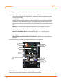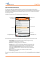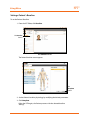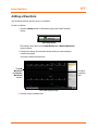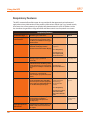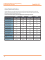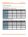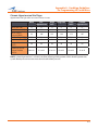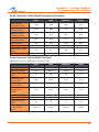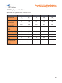
1
HPS
®
with
User Guide
License/Copyright
CAE Healthcare
Human Patient Simulator® (HPS ®) Software and User Guide
THIS IS A LEGAL AGREEMENT. PLEASE READ THIS DOCUMENT CAREFULLY.
The software you are about to access is provided to you pursuant to the purchase of the Product by the legal entity
which employs you, or which you represent (the “Licensee” or You”), from CAE Healthcare. This purchase of the
Product is subject to CAE Healthcare’s Healthcare Education Products General Terms and Conditions (the “HEPGTC”)
and this End-User License agreement (“License”).
This License governs the grant of licenses for the software, in object code only, embedded in or bundled with
the Product or required to operate the Product, as the case may be (“Software”), as well as all related Product
documentation and information (“Data”) supplied by CAE Healthcare either with or separately from the Product,
which items as indicated in the HEPGTC are not sold but licensed.
Acceptance of these terms and conditions must be without modification of any of the terms, conditions and notices
contained herein.
Consequently, please be sure to read the terms of this License carefully.
If You agree to these terms, conditions and other provisions in their entirety, then click the “ACCEPT” button below.
If You do not accept these terms, conditions and other provisions in their entirety, without modification of any sort,
then click the “DECLINE” button below and your access to the Software and Data is prohibited.
1.
DEFINITIONS AND INTERPRETATION
1.1
The preamble forms an integral part of this License.
1.2
Terms with a capital letter defined in the Preamble have the meaning indicated in the Preamble.
Whenever used in this License, the following terms have the meaning set out below:
(a)
“Confidential Information” means any and all scientific and technical information which is in the
possession of, or belonging to, CAE Healthcare and relating to the Product, including without limitation, all Data,
Software, trade secrets, know-how, processes, methodologies, samples, components, analyses, compilations, guides
and other information or documents prepared by CAE Healthcare, its subsidiaries and affiliates and/or their officers,
servants, agents, representatives, employees or advisers which contain or are otherwise generated from or reflect
any CAE Healthcare proprietary information, whether or not covered by intellectual property rights or explicitly
designated as confidential or proprietary, which is disclosed by any means in written, oral, electronic, or any other
form.
(b)
“Purpose” means the use of the Software and the Data solely for the operation and maintenance of the
Product, and the use of the Product solely as an educational tool.
i
License/Copyright
2.
HPS®
LICENSE
2.1
In consideration of Licensee’s agreement and compliance with the terms and conditions contained in the
HEPGTC and in this License, CAE Healthcare grants to Licensee, and Licensee accepts, a personal, non-exclusive,
non-transferable license to use the Software and Data exclusively with the Product, and with the computer on
which this License appears.
2.2
Except for the License granted herein, CAE Healthcare grants no express or implied right under any
patent, copyright, mask work right, trademark, know how or other intellectual property rights. Without limiting the
foregoing, the Licensee shall not obtain any rights to CAE Healthcare’s property, or any part thereof, by implication,
estoppel or otherwise. Title to and full ownership of any trade secrets and other intellectual property rights related
to the Product and components thereof shall remain with CAE Healthcare and, if applicable, its suppliers. For
clarification, Licensee agrees that the source code for the Software is a trade secret of CAE Healthcare and only CAE
Healthcare shall have the right to alter, maintain, enhance or otherwise modify the Software.
2.3
Without limiting the foregoing or any other terms in this License, Licensee shall, and shall ensure that
any person authorized to access the Product, which are limited to Licensee’s employees, agents, representatives,
medical staff and students (“Authorized Users”):
(a)
not copy (save and except for normal back up and disaster recovery purposes provided such copy shall
include CAE Healthcare’s copyright and any other proprietary notices indicated on the Software and Data), ghost,
export or produce any derivative works from the Product, or any part thereof, not network the Product without CAE
Healthcare’s prior written approval, or make it available for concurrent use;
(b)
not sell, attempt to sell or transfer (unless in compliance with the HEPGTC), sublicense, encumber the
Software or Data;
(c)
not modify the Product in any way, combine with other programs, or reverse engineer, screen scratch,
decompile or disassemble any Software nor otherwise attempt to create or derive the source code related thereto;
(d)
not deface or remove any copyright or proprietary notices;
(e)
not use the Product without the Key, if provided with the Product, or attempt to develop or develop any
means or technology which would enable Licensee to bypass the use of the Key to operate the Product;
(f )
prevent anyone other than Authorized Users from accessing or using the Product;
(g)
not incorporate the Product, in whole or in part, to any product or service that Licensee would make
available to a third party, on a commercial basis or not.
2.4
Notwithstanding anything else contained in this License, in no event shall Licensee use the Product and/
or Confidential Information to enable, support, or otherwise aid Licensee or a third party to develop any product,
software or service competitive with any of CAE Healthcare’s products.
2.5
Licensee agrees to grant CAE Healthcare, its agents and representatives, at any time during Licensee’s
normal business hours and upon reasonable prior notice, the right to access to Licensee’s premises, to ensure that
the use of the Product is done at all times in compliance with the terms and conditions of this License.
2.6
CAE Healthcare reserves the right to embed a software security mechanism within the Product to monitor
usage of the Product to verify Licensee’s compliance with this Agreement, as well as to control access to the
Software through use of: a) a hardware lock device and/or b) a license administration software and/or c) a license
authorization key (collectively, the “Key”).
2.7
Some Products may provide Licensee with the option of saving and reproducing the images created by
such Products (“Work”) during their use. In this regard, Licensee hereby recognizes that the entire rights, title and
interests in and to such Work remain the exclusive property of CAE Healthcare. Licensee shall not modify such Work
in any way whatsoever and shall not remove or alter any CAE Healthcare notices. However, Licensee is permitted to
produce and reproduce such Work only for non-commercial educational purposes.
ii
License/Copyright
3.
FEEDBACK
Licensee agrees to provide CAE Healthcare, from time to time, with comments, suggestions, data, information
or feedback (“Feedback”) on the Product. Licensee acknowledges and agrees that such Feedback may be
freely used by CAE Healthcare, at its sole discretion, for the design, development, improvement, marketing and
commercialization of its products and services, without any restrictions based on confidentiality or intellectual
property rights.
4.
TERM AND TERMINATION
4.1
This License shall become effective as of the date of Your execution of this License and shall remain in
effect until terminated as provided hereafter.
4.2
This License terminates immediately upon termination of the HEPGTC.
4.3
CAE Healthcare may terminate this License immediately, upon written notice, should Licensee:
(a)
fail to comply with any of the terms and conditions of this License;
(b)
terminate or suspend its business; make an assignment for the benefit of creditors, or any proceedings
are instituted by any party or against it seeking to declare it bankrupt or insolvent, or seeking liquidation, windingup, reorganization, arrangement, adjustment, protection, relief or composition of its debts under any law relating
to bankruptcy, insolvency, reorganization or relief of debtors, or seeking the entry of an order for relief or the
appointment of a receiver, trustee or other similar official for it or for any substantial part of its property;
4.4
Upon termination of this License, Licensee agrees to immediately discontinue use of the Confidential
Information and the Product, and to return same to CAE Healthcare as well as any copies, summaries or extracts
thereof, with any associated CD ROM(s), DVD, keys, dongles or other devices as may be directed by CAE Healthcare.
At CAE Healthcare’s request, Licensee shall promptly provide a written certificate signed by an officer of Licensee
confirming that such items have been returned to CAE Healthcare or destroyed as so directed by CAE Healthcare.
4.5
The following shall survive and continue in full force and effect notwithstanding any termination of this
License: the obligations of Licensee under Sections 2 (License), 5 (Non-Disclosure); as well as any other clauses
which by their nature and context are intended to survive.
iii
License/Copyright
5.
HPS®
NON-DISCLOSURE
5.1
Licensee agrees to keep this License and all Confidential Information obtained hereunder in strict
confidence, and shall only disclose same a) to Authorized Users solely for the Purpose and provided such access
to the Product conforms, at all times, to the terms and conditions governing the use of the Product contained
herein, or b) if required to be disclosed by law, and only to the extent of such disclosure and limited to the purpose
requested, with prior notice to CAE Healthcare to permit it to seek an appropriate remedy to prevent the disclosure,
or alternatively to agree to the terms of such disclosure.
5.2
The obligations of confidentiality, use and non-disclosure referred to in this Section 5 shall not apply to
information which: (i) is or becomes publicly available through no fault of Licensee; (ii) was already in the rightful
possession of Licensee prior to its receipt from CAE Healthcare; (iii) is independently developed by Licensee,
provided it is not, in whole or in part, related to the Product; and (iv) is obtained by Licensee in good faith and on
a non-confidential basis and without a use restriction from a third party who lawfully obtained and disclosed such
information. However, Confidential Information does not come within the foregoing exceptions merely because
features of it may be found separately or within a general disclosure in the public domain.
5.3
Licensee agrees to be responsible for enforcing the terms of this Section 5 and to take such action, legal
or otherwise, to the extent necessary to cause anyone having access to the Confidential Information to comply with
the terms and conditions set forth herein (including all actions that Licensee would take to protect its own trade
secrets and confidential information but with not less than reasonable care). Licensee shall be responsible and
indemnify, defend and hold harmless CAE Healthcare for any default caused by any such persons.
iv
License/Copyright
6.
IRREPARABLE HARM
6.1
Licensee acknowledges that the Software and Data constitute a special, irreplaceable asset of great value
to CAE Healthcare, and that a breach, in any way, of any of Licensee’s obligations under Sections 2 (License), and 5
(Non-Disclosure) hereof would cause serious and irreparable harm to CAE Healthcare which may not be adequately
compensated for in damages. If the Licensee breaches any of such provisions, Licensee consents to an injunction
being issued against it restraining it from any further breach of such provision, without derogation from any other
remedy which CAE Healthcare may have in the event of such a breach.
7.
WARRANTY, LIMITATION OF LIABILITY
7.1
THE SOLE WARRANTIES PROVIDED BY CAE HEALTHCARE ARE LIMITED TO THE WARRANTIES PROVIDED IN
THE HEPGTC. ANY WARRANTIES PROVIDED ARE PERSONAL AND NOT TRANSFERABLE.
7.2
CAE HEALTHCARE’S LIABILITY SHALL IN NO CIRCUMSTANCES EXCEED THE LIMITATION OF LIABILITY
INDICATED IN THE HEPGTC. LIABILITY, IF ANY, SHALL BE SOLELY FOR DIRECT DAMAGES, NOT TO EXCEED ON A
CUMULATIVE BASIS THE AMOUNT PAID BY LICENSEE FOR THE PRODUCT.
8.
GOVERNING LAW
8.1
This Agreement shall be governed by, subject to, and interpreted according to the laws of the State of
Florida, U. S. A., without regard to its conflict of law rules. In all cases, the Parties expressly exclude and waive the
application of the United Nations Convention on Commercial Agreements for the International Sale of Goods (1980)
(Vienna Sales Convention) as amended.
8.2
The exclusive forum for the resolution of any and all disputes arising out of or in connection with this
Agreement shall be a court of appropriate jurisdiction located in the State of Florida, U.S.A. Each Party hereby
waives any right that it might otherwise have to object to such venue or seek dismissal of the action on the basis
of forum non-conveniens. EACH PARTY HERETO IRREVOCABLY WAIVES, TO THE FULLEST EXTENT PERMITTED
BY APPLICABLE LAW, ANY AND ALL RIGHT TO TRIAL BY JURY IN ANY LEGAL PROCEEDING ARISING OUT OF OR
RELATING TO THIS AGREEMENT.
8.3
Notwithstanding the foregoing, if a party seeks injunctive proceedings to preserve confidentiality
obligations or intellectual property rights, then it is entitled to seek relief before the competent court/body of any
jurisdiction.
v
License/Copyright
9.
HPS®
MISCELLANEOUS
9.1
United States Government Customer: If Licensee is the United States Government (“U.S. Government”) or
a unit or agency of the U.S. Government, the Software and Data are deemed to be “commercial computer software”
and “commercial computer software documentation”, respectively, pursuant to DFAR Section 227.7202 and FAR
Section 12.212 b) as applicable. Any use, modification, reproduction, release, performance, display, or disclosure
of the Software and/or Data by the U. S. Government, or any of its units or agencies shall be governed solely by
the terms of this License and the HEPGTC. Any technical data provided by CAE Healthcare with the Product that is
not covered by the above provisions is deemed to be “technical data-commercial items” pursuant to DFAR Section
252.227.7015(a).
9.2
Amendment. This License may only be amended by the duly authorized representatives of CAE
Healthcare.
9.3
No Waiver: The failure of CAE Healthcare to enforce at any time any of the provisions of this License, or
to require at any time the performance by Licensee of any of the provisions hereof, shall not be construed to be a
waiver of such provisions, nor in any way affect the validity of this License or any part thereof, or the right of CAE
Healthcare thereafter to enforce any such provision.
9.4
No third-party beneficiaries. Nothing in this Agreement shall be construed as creating or giving rise to any
rights for any third parties or any persons other than the parties to this Agreement.
9.5
Notices: Notices or communications pertaining to this Agreement must be given in writing and delivered
to the addressee as indicated in the HEPGTC.
9.6
Preamble/Headings. The preamble forms an integral part of this Agreement. The division of this
Agreement into Clauses, Articles, sections, subsections and other subdivisions and the insertion of headings are for
convenience of reference only and will not affect the construction or interpretation of this Agreement.
9.7
Severability. If any one or more of the provisions of this License shall be held to be invalid, illegal or
unenforceable, the validity, legality or enforceability of the remaining provisions of this Agreement shall not in any
way be affected or impaired thereby.
9.8
Assignment and Succession. Licensee may not assign or delegate this Agreement in whole or in part,
expressly or by operation of law, without CAE Healthcare’s prior written consent. CAE Healthcare may assign this
Agreement, in whole or in part, and/or its rights and obligations, in CAE Healthcare’s sole discretion, to any party.
This Agreement shall be binding upon and enure to the benefit of the parties hereto and their permitted successors
and assigns. Any assignment of this Agreement, or any license granted herein, in violation of the provisions of this
Section shall be void.
9.9
Entire Agreement. This License constitutes the complete agreement of the parties with respect to the
subject matter referred to herein, and supersede any other agreements, written or oral, concerning the subject
matter hereof.
9.10
Language. The parties declare that they have requested and hereby confirm their express wish that this
License, and related agreements and documents be drawn up in the English language and that any notification,
letter or any other communication from a party to the other pertaining thereto shall be solely in the English
language.
End of License
vi
HPS®
viii
Specifications
HPS Specifications
Size
Mannequin
5 ft, 11 inches (180 cm)
Instructor Workstation
18.5” H x 19.1” W x 7.4” D
(46.9 cm x 48.5 cm x 18.9 cm)
Lab Rack
42.5” H x 27” W x 28” D
(108 cm x 69 cm x 71.2 cm)
Weight
Mannequin/Simulator
75 lbs (34 kg)
Lab Rack
256 lbs (159 kg)
Instructor Workstation
20 lbs (9.1 kg)
Environmental Requirements
Ambient Temperature Range
Operation
40°F to 104°F (4°C to 40°C)
Storage
40°F to 122°F (4°C to 50°C)
Maximum Altitude
Instructor Workstation
Maximum operating altitude: 10,000 ft
Maximum storage altitude: 10,000 ft
Maximum shipping altitude:
10,000 ft
ix
HPS®
Specifications
Power
Rack & Mannequin
AC Input:
AC 100 – 220 VAC, 50/60 Hz
Consumption:
Approx. 400 W
Instructor Workstation
AC Input:
AC 100 – 240 VAC, 50/60 Hz
Electrotherapy
x
Defibrillation
Monophasic
Cautions/Warnings
Cautions/Warnings
Please read and understand these cautions and warnings before you begin using the HPS
system.
USE OF THIS EQUIPMENT IN AN UNSPECIFIED MANNER MAY IMPAIR
DESIGNED PROTECTION.
Your safety is in your hands. Be sure to follow the instructions on the proper setup, breakdown
and use of the HPS system.
SHOCK HAZARD
Electrical Safety
• This product must be connected to an electrical outlet that is properly grounded. Precautions
should be taken so that grounding or polarization is not defeated.
• Do not place defibrillator paddles on or adjacent to the ECG patient electrodes or the PACE
patient electrodes. Contact between defibrillator paddles and the ECG/PACE electrodes
may cause injury to the user and damage to the equipment.
• The HPS is tested to work with the Physio Control Model LifePak 11 monophasic
defibrillator. The use of other defibrillators should be certified by CAE Healthcare prior to
use.
• Do not attempt to disassemble the HPS Lab Rack or Portable Rack or service any of the
electrical components.
• Operate the system from a power source with the following rating: 115VAC, 50/60 hertz
(cycles per second) (e.g., North America, Japan).
• Be sure to use the appropriate 110 or 220 power plugs from the rack, depending on the
poser characteristics of your location.
• Do not spill fluids of any kind in or on any piece of HPS/PediaSIM equipment.
General Use Warnings
Electrical System and HPS Rack
• Do not drop, step on or stack anything on the HPS rack.
• Do not clean the HPS Lab Rack front panel with chemical solvents. Use water and a light
soap solution only.
xi
Cautions/Warnings
HPS®
Mannequin
• Do not disassemble factory-assembled parts of the mannequin.
• Apply water to the mannequin only in accordance with the supported clinical procedures
identified in this User Guide.
• Make sure the mannequin is set up on a stable, sturdy work surface to avoid collapsing and causing
injury to users.
• Do not introduce foreign substances into the airway, with the exception of small amounts of
approved silicone-based lubricant.
• The HPS should be operated in ambient temperatures below 104˚ Fahrenheit (40˚ Celsius).
Prolonged operation (more than two hours) in ambient temperatures greater than 104˚ Fahrenheit
(40˚ Celsius) results in anomalous behavior and out of-spec performance.
• Only perform invasive procedures supported by the system as described in applicable sections of
the User Guide.
• Do not pick the mannequin up by the limbs — support head and leverage weight with torso.
• It is essential to power off the entire HPS system before switching the mannequin from the adult
patient mannequin to the pediatric patient mannequin for users with this option.
• Latex is contained within the HPS Mannequin in the vein assembly of the right arm (i.e., IV
arm). Should you need to replace any portion of the vein assembly please take the necessary
precautions.
Gases
• Follow the standard United States Department of Transportation, or applicable national agency’s
warnings and regulations for handling and using compressed gases.
• Use caution when engaging the air and medical gas valves.
Latex Warning
CAE simulators incorporate latex into their design. When performing certain maintenance procedures,
the latex can become exposed. Users with latex sensitivity should take necessary precautions when
handling the simulator while performing those procedures.
xii
Table of Contents
Table of Contents
License/Copyright ����������������������������������������������������������������������������������������������������������������� i
Declaration of Conformity ....................................................................................................vii
Specifications .......................................................................................................................ix
Cautions/Warnings ���������������������������������������������������������������������������������������������������������������xi
Introduction ������������������������������������������������������������������������������������������������������������������������ 1
HPS ���������������������������������������������������������������������������������������������������������������������������������������� 1
Contained in this User Guide ���������������������������������������������������������������������������������������������������� 2
Equipment Overview ............................................................................................................... 4
Human Patient Simulator - HPS: Standard Equipment ............................................................................ 4
Human Patient Simulator - HPS: Optional Equipment . ........................................................................... 4
Health Science HPS: Standard Equipment ............................................................................................... 5
Health Science HPS: Optional Equipment . .............................................................................................. 5
HPS Equipment ........................................................................................................................ 6
HPS Mannequin ...................................................................................................................................... 6
HPS Lab Rack .......................................................................................................................................... 7
Desktop Instructor Workstation . ........................................................................................................... 14
Wireless Remote Control ....................................................................................................................... 14
TouchPro Monitor . ................................................................................................................................ 14
Drug Recognition System ...................................................................................................................... 15
OxSim ................................................................................................................................................... 16
Monitor Interface .................................................................................................................................. 16
Wireless Microphone and Receiver ........................................................................................................ 17
Replacement Kit . .................................................................................................................................. 17
xiii
HPS®
Table of Contents
Diagnostic Peritoneal Lavage ................................................................................................................ 18
Tablet Instructor Workstation................................................................................................................. 18
Anesthesia Delivery System .................................................................................................................. 18
Anesthesia Gas Accessory Kit . ............................................................................................................... 18
Gas Accessory Kit . ................................................................................................................................. 18
TM
TM
Trauma/Disaster Casualty Kit (TDCK ) ............................................................................................... 19
Moulage Kit .......................................................................................................................................... 19
Tool Kit .................................................................................................................................................. 20
®
PediaSIM Plug and Play Mannequin . ................................................................................................... 20
®
METIVision ........................................................................................................................................... 21
METI FX ................................................................................................................................................. 21
Hands-Free Training Cables ................................................................................................................... 22
HPS with Müse Learning Applications and Training Courses . ................................................................ 23
HPS with Müse Setup ����������������������������������������������������������������������������������������������������������25
Before Beginning Setup �������������������������������������������������������������������������������������������������������� 26
Step 1: Place the Simulator in the Work Area �������������������������������������������������������������������������� 27
Step 2: Connect the Umbilical Assembly .................................................................................. 28
Step 3: Connect the Gases ....................................................................................................... 30
Step 4: Connect the Instructor Workstation ............................................................................. 31
Step 5: Connect the OxSim (Optional) ...................................................................................... 32
Step 6: Connect Clinical Monitors (Optional) ............................................................................ 34
Step 7: Ensure All Gas Supplies Are Turned off .......................................................................... 34
Step 8: Turn on Patient Monitors ............................................................................................. 34
Step 9: Power on the HPS Lab Rack .......................................................................................... 35
Step 10 - Option 1: Power on and Log Into the Desktop Instructor Workstation .......................... 36
Step 10 - Option 2: Power on and Log Into the Optional Tablet Instructor Workstation ................ 36
xiv
Table of Contents
Step 11: Activate the Gas Supplies .......................................................................................... 36
Step 12: Launch Müse ............................................................................................................ 36
Configuring a TouchPro or Wireless Remote Computer.............................................................. 38
System Requirements ............................................................................................................ 46
Using Müse...........................................................................................................................47
Starting the Application......................................................................................................... 47
Navigating the Home Page..................................................................................................... 50
The SCE Selection Panel......................................................................................................................... 51
The SCE Library...................................................................................................................................... 53
The SCE Summary Panel........................................................................................................................ 57
Printing SCEs.......................................................................................................................................... 58
Running an SCE...................................................................................................................... 59
Connecting to the Simulator................................................................................................... 60
Using the Patient Status Display............................................................................................................ 60
The Event Logs....................................................................................................................................... 62
Displaying Patient Records..................................................................................................................... 62
Adding a Scenario to a Running SCE....................................................................................................... 65
Changing Physiology............................................................................................................................. 66
SCE Time Controls................................................................................................................................... 80
Using the Event Recorder to Save States................................................................................................ 82
Creating a New Patient.......................................................................................................................... 84
Resetting a Patient................................................................................................................................ 85
The Medication Monitor......................................................................................................................... 86
Returning to the Home Page.................................................................................................................. 88
Stopping the SCE.................................................................................................................................... 88
xv
Table of Contents
HPS®
Developing SCEs..................................................................................................................... 90
Creating a New SCE................................................................................................................................ 90
The SCE Editor........................................................................................................................................ 92
Developing Scenarios............................................................................................................100
Creating a New Scenario...................................................................................................................... 100
Editing a Scenario................................................................................................................................ 102
The Scenario Designer.......................................................................................................................... 104
Adding Scenario States........................................................................................................................ 107
Modifying Scenario States................................................................................................................... 108
Deleting Scenario States...................................................................................................................... 115
Deleting Parameters and Transitions.................................................................................................... 116
Saving the Scenario............................................................................................................................. 117
Saving States to the State Library........................................................................................................ 118
Emptying the Trash.............................................................................................................................. 120
Administrative Tools..............................................................................................................122
History................................................................................................................................................. 123
System Administration........................................................................................................................ 124
Account Profile..................................................................................................................................... 142
Favorite SCEs........................................................................................................................................ 144
Using TouchPro...................................................................................................................147
Accessing the TouchPro Software............................................................................................147
Modifying the TouchPro Display.............................................................................................149
Selecting a Preconfigured Layout...........................................................................................149
Changing a Waveform or Numeric Display...............................................................................151
xvi
Table of Contents
Adding a Waveform...............................................................................................................152
Adding a Numeric Display......................................................................................................154
Moving a Waveform or Numeric Display..................................................................................155
Saving a Layout.....................................................................................................................156
Sounds.................................................................................................................................157
12-Lead ECG..........................................................................................................................158
NIBP Cycling and Manual NIBP...............................................................................................160
Patients................................................................................................................................162
Configuring the TouchPro Software........................................................................................163
Changing the TouchPro Language..........................................................................................164
Exiting the TouchPro Software...............................................................................................164
Using the HPS.....................................................................................................................165
Parameters ..........................................................................................................................166
Neurological Features ...........................................................................................................169
Eyes . ................................................................................................................................................... 170
Thumb Twitch ..................................................................................................................................... 171
Respiratory Features .............................................................................................................172
Realistic Upper Airway ........................................................................................................................ 175
Variable Upper/Lower Airway Resistance ............................................................................................ 175
Cricothyrotomy ................................................................................................................................... 178
Breakaway Teeth ................................................................................................................................. 178
Chest Tube . ......................................................................................................................................... 179
Needle Decompression . ...................................................................................................................... 181
xvii
Table of Contents
HPS®
Cardiovascular Features ........................................................................................................182
Pulses . ................................................................................................................................................ 184
5-Lead ECG .......................................................................................................................................... 185
Myocardial Ischemia ........................................................................................................................... 186
Manual Blood Pressure . ...................................................................................................................... 187
Korotkoff Sounds (Five Phases) ........................................................................................................... 188
Defibrillation . ..................................................................................................................................... 189
Cardiac Pacing ..................................................................................................................................... 190
Pericardiocentesis ............................................................................................................................... 191
Fluids ...................................................................................................................................192
Circulation . ......................................................................................................................................... 193
Genitourinary System ......................................................................................................................... 195
Pharmacology System . ....................................................................................................................... 199
Gastrointestinal Features ......................................................................................................202
Diagnostic Peritoneal Lavage .............................................................................................................. 202
Sounds .................................................................................................................................203
Bowel Sounds ..................................................................................................................................... 203
Breath Sounds . ................................................................................................................................... 204
Heart Sounds ...................................................................................................................................... 205
Wireless Voice Capability ..................................................................................................................... 206
Drug Recognition ��������������������������������������������������������������������������������������������������������������207
Labels ���������������������������������������������������������������������������������������������������������������������������������207
Stopcock Manifold ���������������������������������������������������������������������������������������������������������������208
IV Bag and Stake Set ������������������������������������������������������������������������������������������������������������208
IV Access Ports ���������������������������������������������������������������������������������������������������������������������208
Drug Recognition Syringe Pump Mechanism ��������������������������������������������������������������������������209
xviii
Table of Contents
Drug Recognition Circuit Board ���������������������������������������������������������������������������������������������209
Fluid Reservoir ��������������������������������������������������������������������������������������������������������������������209
Setup ����������������������������������������������������������������������������������������������������������������������������������210
Operation ����������������������������������������������������������������������������������������������������������������������������212
Troubleshooting the Stopcock ����������������������������������������������������������������������������������������������213
Cleanup ������������������������������������������������������������������������������������������������������������������������������214
Anesthesia and Scavenging �����������������������������������������������������������������������������������������������215
Introduction ������������������������������������������������������������������������������������������������������������������������215
The Anesthesia Delivery System ��������������������������������������������������������������������������������������������216
Hardware Setup Instructions ������������������������������������������������������������������������������������������������217
Step 1: Set Up External Components ................................................................................................... 217
Step 2: Set Up the Anesthesia Delivery System in the HPS Lab Rack . .................................................. 218
Step 3: Start Müse .............................................................................................................................. 218
Operation ����������������������������������������������������������������������������������������������������������������������������219
Cleanup ������������������������������������������������������������������������������������������������������������������������������219
Other Considerations �����������������������������������������������������������������������������������������������������������220
Scavenging �������������������������������������������������������������������������������������������������������������������������220
xix
Table of Contents
HPS®
PediaSIM HPS with Müse����������������������������������������������������������������������������������������������������221
PediaSIM Patient Profiles �����������������������������������������������������������������������������������������������������222
PediaSIM SCEs����������������������������������������������������������������������������������������������������������������������223
PediaSIM Base SCEs . ........................................................................................................................... 223
PediaSIM Preconfigured SCEs .............................................................................................................. 223
Condition Guidelines for Programming PediaSIM HPS with Müse ��������������������������������������������225
HPS Care and Maintenance ������������������������������������������������������������������������������������������������243
HPS Warranty Programs �������������������������������������������������������������������������������������������������������243
General Information . .......................................................................................................................... 243
Units Out of Agreement ...................................................................................................................... 243
How to Contact Customer Service ...........................................................................................244
Contract Period ................................................................................................................................... 245
Limitations of Agreement ................................................................................................................... 245
Return Materials Authorization ........................................................................................................... 245
System Software Upgrade Support ........................................................................................246
Pricing Structure ..................................................................................................................246
Time and Materials ............................................................................................................................. 246
xx
Table of Contents
Breakdown ...........................................................................................................................247
Step 1: Clean the Simulator and the Fluid System ............................................................................... 247
Step 2: Shut Down the Software ......................................................................................................... 247
Step 3: Power Off the HPS Lab Rack . ................................................................................................... 248
Step 4: Power Off the Clinical Monitor ................................................................................................. 248
Step 5: Turn Off All Gases . ................................................................................................................... 248
Maintenance Advice �������������������������������������������������������������������������������������������������������������249
The Mannequin . ................................................................................................................................. 249
Care of Electronic Equpiment .............................................................................................................. 249
Checking the Airway ........................................................................................................................... 250
Removing the Chest Skin .................................................................................................................... 251
Replacing the Chest Skin ..................................................................................................................... 251
Replacing the Chest Tube Foam Inserts ............................................................................................... 252
Maintaining Trauma Features . ............................................................................................................ 253
Maintaining the IV System .................................................................................................................. 255
Maintaining the GU System ................................................................................................................ 256
Repairing Cuts and Abrasions to the Mannequin . ............................................................................... 257
Using the IV Arm Kit ............................................................................................................................ 258
Drug Recognition Barcode Labels . ...................................................................................................... 258
xxi
Table of Contents
HPS®
Recommended Clinical Supply Sizes.....................................................................................259
Appendix A - Condition Guidelines for Programming HPS with Müse . .................................... A-1
Appendix B - Müse Parameter Descriptions .......................................................................... B-1
Appendix C - Base Patients ...................................................................................................C-1
Appendix D - The Ischemic Index (Death Spiral) .................................................................... D-1
Appendix E - hs6 Files and Müse............................................................................................E-1
Appendix F - Configuring the HPS Gas Analyzer......................................................................F-1
xxii
Introduction
Introduction
As the worldwide leader in patient simulation technology and education, CAE Healthcare is
excited to introduce the Human Patient Simulator (HPS). With CAE Healthcare’s proprietary
human physiology model at its core, the HPS is designed to automatically determine patient
responses to user interventions in real time.
HPS
What makes the HPS so unique is its versatility and usability. Combining intricate systems
design and flexible user-oriented software, the HPS creates realistic learning experiences that
replicate the complexities of human physiology with reactive eyes, heart and breath sounds,
palpable pulses and a myriad of other features that mirror a true and accurate representation
of the human body.
1
Introduction
HPS®
Contained in this User Guide
This User Guide has been designed for quick access to information on how to use and maintain
the HPS system. Please be sure to read and follow the Cautions and Warnings on the pages
preceding the Table of Contents. This is for the safety of users as well as for the protection of
the simulator.
Before using the system, follow the step-by-step instructions included in the HPS with Müse
Setup section.
The Using the Software Section section provides instructions on the use of the various
software features as well as how to create and save a new patient.
The Using HPS with Müse section includes information on how the simulator and software
components work and the functionality that each supports. Various clinical interventions
are explained in this section, along with how these interventions isolate critically important
learning objectives. In addition, detailed instructions are provided on how to develop and save
custom patients.
2
Introduction
The Drug Recognition section includes usage and orientation content to use this feature of
the HPS system. This section also includes content pertaining to the use of the bar code reader.
The Anesthesia and Scavenging section applies to users with the optional anesthesia
package. This section provides important usage instructions as well as scavenging guidelines
to support the use of this optional equipment component.
The PediaSIM HPS with Müse section is available for users who purchased the HPS PediaSIM.
The PediaSIM can be purchased as an accessory to the HPS system or as a stand-alone
simulator. For the stand-alone user, all of the pertinent usage information as it pertains to
the PediaSIM is included in this one complete section. For users using the PediaSIM as an
accessory, this section provides a content overview to help orient the user to the system
features and functionality.
The HPS Care and Maintenance section contains warranty details and cleanup and care
instructions that must be followed to ensure optimal functioning of the HPS system.
3
Introduction
Equipment Overview
The HPS is comprised of three main components - the HPS Lab Rack, the Instructor
Workstation and the HPS mannequin. There are two configurations for the HPS: the Human
Patient Simulator - HPS and the Health Science HPS.
Human Patient Simulator - HPS: Standard Equipment
HPS Mannequin
HPS Lab Rack
Desktop Instructor Workstation
Wireless Remote Control
Drug Recognition System
OxSim
Monitor Interface
Wireless Microphone and Receiver
Replacement Kit
Diagnostic Peritoneal Lavage
Human Patient Simulator - HPS: Optional Equipment
Tablet Instructor Workstation
TouchPro Monitor
Anesthesia Delivery System
Anesthesia Gas Accessory Kit
Gas Accessory Kit
Trauma/Disaster Casualty Kit (TDCK)
Moulage Kit
Tool Kit
PediaSIM Plug and Play Mannequin
METIVision
METI FX
Hands-Free Training Cables
HPS Learning Applications and Training Courses
Windows is a registered trademark of the Microsoft Corporation in the United States and other countries.
4
HPS®
Introduction
Health Science HPS: Standard Equipment
HPS Mannequin
HPS Lab Rack
Desktop Instructor Workstation
TouchPro Monitor
Wireless Microphone and Receiver
Replacement Kit
Diagnostic Peritoneal Lavage
Health Science HPS: Optional Equipment
Tablet Instructor Workstation
Wireless Remote Control
Drug Recognition System
OxSim
Monitor Interface
Gas Accessory Kit
Trauma/Disaster Casualty Kit (TDCK)
Moulage Kit
Tool Kit
PediaSIM Plug and Play Mannequin
METIVision
METI FX
Hands-Free Training Cables
HPS Learning Applications and Training Courses
Windows is a registered trademark of the Microsoft Corporation in the United States and other countries.
5
HPS®
Introduction
HPS Equipment
The descriptions on the following pages outline standard and optional components of the
HPS system. Refer to the Human Patient Simulator - HPS: Standard Equipment on page 4 or the
Health Science HPS: Standard Equipment on page 5 for a list of standard components included
with your system configuration.
HPS Mannequin
All patient assessments and clinical interventions are played out on the HPS mannequin,
which represents a human patient. At 5’ 11” (180 cm) tall and weighing 75 pounds (34 kg), it
is fully operational in the supine and lateral positions. It can be placed on a gurney, operating
room table or on the ground. The mannequin offers features such as breath and heart sounds,
palpable pulses, patient voice, genitourinary features and airway management features.
Umbilical Assembly
The Umbilical Assembly is a long, bundled system of hoses and an electrical cable attached to
the HPS mannequin in the perineum area. The Umbilical Assembly attaches the mannequin to
the HPS Lab Rack.
The Umbilical Assembly
The Umbilical Assembly is about 12 feet (4 meters) long and is made up of two bundled
systems: the fluidic/pneumatic pigtail and the electrical pigtail. The large square electrical
connector attaches to the back of the HPS rack, while each of the fluidic/pneumatic hoses
attaches to labeled ports on the back of the rack.
6
Introduction
HPS Lab Rack
The HPS Lab Rack is the hub of communication, power and pneumatics for the HPS system.
It contains a central power supply, an Ethernet switch, lung bellows and other essential
components that drive the simulator’s physical responses.
HPS Lab Rack
The following descriptions explain the configuration of the HPS Lab Rack.
7
Introduction
HPS®
The Back of the Rack
The following components are exposed at the back of the rack:
MUX 6 - An open serial port. May be used to connect the TDCK.
MUX 10 - An open serial port.
Exhaust Port - Used for scavenging anesthetic gases.
Audio Out - Enables the simulator’s audio outputs to be connected directly into an
audio system.
NOTE: Only Heart Sounds are transmitted through the audio port. Sounds are
monophonic.
Genitourinary Pump - Forces water in and out of the mannequin through the system
hoses.
SpO2 Probe Port - Provides communication between the OxSim and the
rack.
Bar Code Reader Port - Provides communication between the Bar Code Reader and
the rack.
Flow Meter - Measures the flow of the fluid to the chest tube and pericardiocentesis
features of the HPS.
Power Switch - Toggles simulator power on and off.
8
Introduction
Cover
removal grips
Exposed ports
The Back of the Rack
MUX 6 port
SPO2 PROBE port
MUX 10 port
BAR CODE READER port
EXHAUST port
Flow meter
AUDIO OUT
Power switch
Genitourinary
pump
The Exposed Ports at the Back of the Rack
9
HPS®
Introduction
The upper back of the rack also contains the drug recognition system, which measures
the volume displaced when drugs are given and pushes fluids from the drug system into a
collection bag. The upper back of the rack is covered by a plastic cover. To remove the cover,
hold the grips on both sides of the cover and pull up, then out.
Drug recognition
system
The Back of the Rack with the Cover Removed
10
Introduction
The Front of the Rack
The front of the rack is protected by a plastic cover. To remove the cover, hold the grips on
both sides and pull up, then out.
Cover
removal grips
Front of Rack with Cover in Place
11
HPS®
Introduction
The following components can be accessed from the front of the rack:
Sim Cube* - Processes noninvasive blood pressure (NIBP) data from the software and
drives the mannequin’s physical responses so patient monitoring equipment may be
used to measure NIBP.
Syringe Pump - Installed in the rack when the anesthesia system option is in place.
Delivers liquid anesthetic agents to a vaporizer before they are sent to the mannequin,
providing a realistic exhalation of agents. The syringe pump can also be accessed via
the anesthesia delivery system panel (see The Anesthesia Delivery System Panel on page
13).
Vaporizer - Installed in the rack when the anesthesia system option is in place.
Evaporates anesthetic agents before sending them to the mannequin.
Bellows - Provide the lung functionality of the HPS system.
Mass Flow Controllers (MFCs) - Control the flow of O2, CO2, N2 and N2O to the
mannequin.
Gas Analyzer - Analyzes the gases going into and flowing out of the mannequin.
MUSE Universal Simulator Engine Circuit Boards - Control various components of
the rack.
*Optional for Health Science HPS, standard for Human Patient Simulator - HPS
Vaporizer
Syringe pump
MUSE
Bellows
Mass flow contollers
Sim cube
Gas analyzer
Front of Rack with Cover Removed
IMPORTANT: Do not alter or modify the settings of any of the components inside the rack
except the Syringe Pump and Vaporizer. Doing so affects performance.
12
Introduction
The Anesthesia Delivery System Panel
The anesthesia delivery system is optional for the Health Science HPS and the Human Patient
Simulator - HPS. When the anesthesia delivery system is installed, the syringe pump can be
easily accessed from the panel at the top of the rack.
The access
panel
The Anesthesia Delivery System Access Panel
NOTE: The Anesthesia Delivery System is optional. If the system is not installed on your
simulator, the access panel reveals only an empty bracket.
13
Introduction
HPS®
Desktop Instructor Workstation
The Desktop Instructor Workstation is a desktop computer that utilizes the Müse Software to
operate as the main simulation control center.
The computer runs the underlying mathematical models that generate the physiological data
that is realized on the simulator. Instructors control the simulator session from the workstation
by selecting Simulated Clinical Experiences (SCEs) that meet the objectives of the training
module.
IMPORTANT: All CAE Healthcare computer components are preconfigured for use with
the HPS system. There are no software installation or configuration steps required. Only
approved CAE Healthcare applications should be installed or run on the HPS computer
system.
Wireless Remote Control
Optional for Health Science HPS
The Wireless Remote Control can be used when the use of an Ethernet cable and a power cord
is restrictive. It is preconfigured with the same software and functions in the same way as the
Instructor Workstation (product #HPS-501).
TouchPro Monitor
Optional for Human Patient Simulator - HPS
The optional TouchPro Monitor is a flat-panel, touchscreen monitor that connects wirelessly to
the Instructor Workstation and is used to run the TouchPro software.
14
Introduction
Drug Recognition System
Optional for Health Science HPS
The HPS and PediaSIM both incorporate barcode technology along with an extensive drug
library as part of the drug administration learning features. This system gives practicing
clinicians a safe environment to learn drug administration prior to working on real human
patients. The Enhanced Drug Recognition system (product #HPS-401) is a complete package
that includes the following:
• The Barcode Reader (or Stopcock Manifold)
• Three Sheets of Barcode Labels
NOTE: The remaining components, including an IV bag with distilled water, two stake sets, an
empty IV bag and 10 mL, 2 mL or 50 mL syringes are all user-supplied.
The individual barcode labels identify a complete library of drugs from a wide range of
classifications. When appropriately applied to a syringe, each label uniquely identifies the drug
and concentration to the HPS system using the barcode reader (or Stopcock Manifold). The
Stopcock Manifold electrically connects to the back of the rack and to the IV access ports on
the patient mannequin.
15
HPS®
Introduction
OxSim
Optional for Health Science HPS
The OxSim is used to provide SpO2 data to the monitoring equipment used during the
simulation session. A standard SpO2 finger probe can be placed on the Index to obtain an SpO2
reading for a virtual patient.
Index
OxSim
Monitor Interface
Optional for Health Science HPS
The monitor interface is used to connect the simulator to a standard clinical monitor, allowing
for the display of a wide range of patient parameters (product #MI-001).
Monitor Interface
16
Introduction
Wireless Microphone and Receiver
The wireless microphone and receiver are used for the patient voice feature of the HPS system.
The receiver is housed inside the rack. The wireless microphone includes an adjustable lapel
clip, volume control and mute.
Wireless Microphone and Receiver
Replacement Kit
The Replacement Kit includes the IV Arm Kit, Trauma Features Kit, Airway Kit and Genitourinary
(GU) Kit. The items contained in each kit are listed below.
IV Arm Kit
• Venous Tubing Splicing Kit
• 140 mL syringe and IV solution sets
Trauma Features Kit
• Chest tube foam inserts
• Chest tube receptacles
• Chest tube priming hose
• Diagnostic peritoneal lavage abdominal insert
• Standard abdominal insert
Airway Kit
• Spare neck skins
• Silicone spray
• Spool of red airway tape
Genitourinary (GU) Kit
• Interchangeable male/female genitalia
• IV solution set
17
Introduction
HPS®
Diagnostic Peritoneal Lavage
The Diagnostic Peritoneal Lavage (DPL) abdominal cavity allows for the performance of DPL
on the mannequin and is interchangeable with the standard abdominal cavity. The DPL cavity
has a slit down the center and can be filled with distilled water tinted with red food coloring.
When tape is placed over the slit in the cavity and a needle is placed in it, fluid is aspirated
back similar to when DPL is performed in the clinical setting.
Tablet Instructor Workstation
Optional for Human Patient Simulator - HPS and Health Science HPS
The Tablet Instructor Workstation is an optional, ruggedized tablet computer that can be used
instead of the Desktop Instructor Workstation to run the Müse software. An additional Müse
license is provided with this option.
NOTE: The Tablet Instructor Workstation cannot perform calibration utilities. The Desktop
Instructor Workstation is needed to perform these functions. Additionally, the Tablet Instructor
Workstation and the Desktop Instructor Workstation cannot be used at the same time. Müse
content is not shared between the Tablet and Desktop Instructor Workstations.
Anesthesia Delivery System
Optional for Human Patient Simulator - HPS, not included with Health Science HPS
The Anesthesia Delivery System is optional for the Human Patient Simulator - HPS
configuration. It can be installed in the HPS Lab Rack and allows for the use and detection of
real anesthetic agents (product #HPS-300).
Anesthesia Gas Accessory Kit
Optional for Human Patient Simulator - HPS, not included with Health Science HPS
The Anesthesia Gas Accessory Kit is optional for the Human Patient Simulator - HPS
configuration. The kit contains regulators and hoses to connect carbon dioxide, oxygen, air,
inert gas and carbon dioxide to the HPS Lab Rack, along with the components necessary to
connect the HPS Lab Rack to a scavenging system (product #GAS-002).
Gas Accessory Kit
Optional for Human Patient Simulator - HPS and Health Science HPS
The optional Gas Accessory Kit contains regulators and hoses to connect carbon dioxide,
oxygen, air and inert gas tanks to the HPS Lab Rack (product #GAS-001).
18
Introduction
Trauma/Disaster Casualty Kit (TDCK)
Optional for Human Patient Simulator - HPS and Health Science HPS
The TDCK adds to the fidelity of a training session by providing the means to add the
automatic, software-controlled flow of blood, mucous and secreted fluids from the mannequin
(product #TF-005).
The Trauma Disaster Casualty Kit
Moulage Kit
Optional for Human Patient Simulator - HPS and Health Science HPS
The Moulage Kit is available separately or as part of the Trauma Disaster Casualty Kit.
Moulage Kit
The Moulage Kit is used to simulate injuries and trauma (product #MODS-999).
19
HPS®
Introduction
Tool Kit
Optional for Human Patient Simulator - HPS and Health Science HPS
To simplify common adjustments and periodic repairs, CAE Healthcare has put together a kit
containing tools selected for use with the simulator (product #TOL-001).
The Tool Kit
PediaSIM Plug and Play Mannequin
Optional for Human Patient Simulator - HPS and Health Science HPS
The optional PediaSIM Plug and Play Mannequin can interface with either of the HPS models
to simulate the unique physiology of a pediatric patient (product #HPS-016).
PediaSIM Plug and Play Mannequin
20
Introduction
METIVision
Optional for Human Patient Simulator - HPS and Health Science HPS
METIVision is a fully integrated, digital audio-visual management system that is datasynchronized in real-time for use with CAE Healthcare simulators. METIVision is the only
solution available with the capability to not only capture and store simulation data, but to
also broadcast and review any medical simulation exercise using CAE Healthcare simulators.
Complete with physiologic data logs, event logs, pharmacology logs and patient monitoring
data, METIVision offers the capability to provide a complete record of simulation exercises for
debriefing, assessment and evaluation (product #MTV-001).
METIVision Console
METI FX
Optional for Human Patient Simulator - HPS and Health Science HPS
CAE Healthcare takes realism to the next level with METI FX, a realistic set for advanced
moulage wound simulation and special effects. METI FX includes incredibly lifelike wounds
that accurately replicate muscle, tissue and subcutaneous fat and reflect the true physical
nature of a wound and its treatment. METI FX comes complete with CAE Healthcare’s own
educational learning tools – a set of how-to treatment cards explaining procedures and
learning objectives for both civilian and military patient scenarios (product #MFX-100).
METI FX Simulation
21
HPS®
Introduction
Hands-Free Training Cables
Optional for Human Patient Simulator - HPS and Health Science HPS
Hands-Free Training Cables connect to most popular defibrillators and cardiac pacing units
and take the place of non-reusable electrode pads.
Three different cable designs are available to support the most popular defibrillation and
pacing equipment. Each cable kit includes posts that attach to the defibrillator or pace
locations on HPS.
Zoll (Zoll Medical Corporation)
(product #ACC-006)
Physio-Control (Medtronic, Inc.)
(product #ACC-007)
Philips (Koninklijke Philips Electronics, N.V.)
(product #ACC-008)
22
Introduction
HPS with Müse Learning Applications and Training Courses
HPS with Müse Learning Applications
Learning applications enhance the use of the simulator by providing preprogrammed
scenarios and corresponding support documentation (e.g., course objectives, instructor’s
notes) that can be readily integrated into a lesson plan, a specific curriculum or an educational
program. The following Learning applications are available for HPS with Müse.
Advanced Cardiac Life Support (ACLS)
Adult Nursing
Cardiopulmonary Critical Situations (CCS)
Disaster Medical Readiness (DMR)
Emergency Medical Services (EMS) Learning Application 1
Emergency Medical Services (EMS) Learning Application 2
Emergency Medical Services (EMS) Learning Application 3
Emergency Medical Services (EMS) Learning Application 4
Foundations of Nursing Practice
Patient-Centred Acute Care Training (PACT) Simulation
Pediatric Advanced Life Support (PALS) for PediaSIM
Pediatric Emergencies
Pediatric Nursing
Perioperative Management
Program for Nursing Curriculum Integration (PNCI)
Program for Nursing Curriculum Integration (PNCI)
Respiratory Education Simulation Program (RESP) Learning Application 1
Respiratory Education Simulation Program (RESP) Learning Application 2
Respiratory Education Simulation Program (RESP) Learning Application 3
Tactical Medical Care (TMC)
23
Introduction
HPS®
HPS with Müse Training Courses
HPS Basic and Advanced courses offer learners at all levels in-depth instruction in the setup,
operation, development of scenarios and maintenance related to the use of the HPS.
The HPS Basic course provides learners with an overview of the system and its components, as
well as an introduction to patient creation and scenario design.
HPS Basic - two days at CAE Healthcare facility
HPS Basic On-Site - two days at learner-defined facility
HPS Basic On-Site Physician Instructor - two days at learner-defined facility with
physician-led instruction
The HPS Advanced course builds upon the concepts introduced in the prerequisite Basic
course. After a quick review of the Basic course, Advanced instruction spends the majority of
the two days providing learners with the ability to design patients and scenarios that can be
used immediately upon completion of the course.
HPS Advanced - two days at CAE Healthcare facility
HPS Advanced On-Site - two days at learner-defined facility
HPS Advanced On-Site Physician Instructor - two days at learner-defined facility with
physician-led instruction
24
HPS with Müse Setup
HPS with Müse Setup
The following pages guide you through assembling and configuring HPS. Below is a list of the
steps required to prepare HPS for operation.
Setting Up HPS
1
Place the Simulator in the Work Area
2
Connect the Umbilical Assembly
3
Connect the Gases
4
Connect the Instructor Workstation
5
Connect the OxSim (Optional)
6
Connect Clinical Monitors (Optional)
7
Ensure all Gas Supplies Are Turned Off
8
Turn on Patient Monitors and Other Clinical Equipment
9
Power on the HPS Lab Rack
10
Power on and Log into the Instructor Workstation
11
Activate the Gas Supplies
12
Launch Müse
25
HPS with Müse Setup
HPS®
Before Beginning Setup
Proper operation of the HPS simulator requires the correct configuration. Before setting up the
system, keep in mind these basic guidelines:
Understand the Cautions/Warnings information included in the beginning of this User Guide.
Follow the sequence of steps carefully,
Complete all steps in order, and
Do not power on any components until instructed in the text.
KEEP all original shipping materials, including the BOXES. Warranty and repair items must be
return-shipped to CAE Healthcare in their original packaging.
Because shipping materials should be stored and retained, be sure all protective packing
materials and unused ancillary computer parts are secured.
If unpacking HPS for the first time, careful use of a box cutter protects both the packaging and
the product.
The Setup Map and Quick Start Chart cover these same steps in abbreviated fashion.
26
HPS with Müse Setup
Step 1: Place the Simulator in the Work Area
Select a work area with enough room for all equipment, providing ample space for easy
access to the simulator. At least a 12’ x 14’ (3.5 meter x 4.5 meter) work area is recommended
for movement of learners and positioning of standard components around the simulator. If
you are using optional items such as anesthesia, drug recognition, Wireless Remote Control or
TDCK, you need to allow additional room for those components.
The HPS Mannequin
Make sure a multi-plug AC power outlet exists within the workspace to power the HPS Lab
Rack, Instructor Workstation and monitoring equipment.
Before placing the simulator on a surface, be certain the surface can easily support 75 pounds
(34 kg).
NEVER lift the mannequin by the LIMBS. Leverage the torso of the simulator and support the
head while lifting.
NOTE: Be sure to use the appropriate 110 or 220 power plugs from the rack, depending on the
power caracteristics of your location.
27
HPS®
HPS with Müse Setup
Step 2: Connect the Umbilical Assembly
a. Locate the long bundled system of fluidic/pneumatic hoses and an electrical
pigtail attached to the mannequin in the perineum area. This is the umbilical
assembly.
The Umbilical Assembly
b. Attach the pin-fitting assembly on the electrical pigtail to the back of the HPS Lab
Rack, being careful not to bend any of the pins.
Electrical pigtail pinfitting assembly
Attaching the Electrical Pigtail
28
HPS with Müse Setup
c. Attach the Pneumatic Left and Pneumatic Right hoses to the labeled ports on the
back of the HPS Lab Rack.
Pneumatic
Left hoses
Pneumatic
Right hoses
Attaching the Pneumatic Left and Pneumatic Right Hoses
d. Attach the Left Lung and Right Lung hoses to the labeled ports on the back of the
HPS Lab Rack.
Left Lung
hose
Right Lung
hose
Attaching the Left Lung and Right Lung Hoses
29
HPS®
HPS with Müse Setup
Step 3: Connect the Gases
In order to use the HPS, Compressed Air, Oxygen (O2), Carbon Dioxide (CO2) and Nitrogen (N2)
must be supplied via central air source or cylinder size G, H or K. Nitrous Oxide (N2O) may also
be supplied for anesthesia delivery if desired. All gases must be calibrated to 50 psig/345 kPa.
a. Ensure the supply pressure of all gas tanks and the Compressed Air tank are set to
50 psig/345 kPa.
b. Connect Compressed Air to the labeled port on the back of the HPS Lab Rack.
c. Connect Oxygen (O2) to the labeled port on the back of the HPS Lab Rack.
d. Connect Carbon Dioxide (CO2) to the labeled port on the back of the HPS
Lab Rack.
e. Connect Nitrogen (N2) to the labeled port on the back of the HPS Lab Rack.
f. Connect Nitrous Oxide (N2O) to the labeled port on the back of the HPS Lab Rack
(Optional).
Oxygen
(O2) port
Carbon Dioxide
(CO2) port
Compressed Air
(AIR) port
Nitrogen
(N2) port
Nitrous Oxide
(N2O) port
Connecting the Gases to the Back of the HPS Lab Rack
IMPORTANT: DO NOT turn on the gases until instructed in Step 11 on page 36.
30
HPS with Müse Setup
Step 4: Connect the Instructor Workstation
a. Place the Desktop or Tablet Instructor Workstation at the location where it will be
used.
b. Connect one end of the Ethernet cable to the Instructor Workstation.
c. Connect the other end of the Ethernet cable to the HPS Lab Rack.
Connecting the Ethernet Cable to the HPS Lab Rack
31
HPS®
HPS with Müse Setup
Step 5: Connect the OxSim (Optional)
a. Connect the OxSim cable to the SpO2 PROBE port on the back of the rack.
Connect the
OxSim cable to the
SpO2 PROBE port
Connecting the OxSim cable to the Back of the Rack
b. Ensure there is no battery in the OxSim and the power switch is in the OFF
position (away from the red dot).
Ensure there is no
battery in the battery
compartment
Ensure the power
switch is in the OFF
position (away from the
red dot)
The OxSim Battery Compartment and Power Switch
32
HPS with Müse Setup
c. Connect the other end of the OxSim cable to the OxSim.
Connect the OxSim
cable to the OxSim
Connecting the OxSim Cable to the OxSim
NOTE: It is recommended that the OxSim be secured to a patient monitor, anesthesia machine,
equipment rack or other secure surface using a hook-and-loop fastener such as Velcro®.
33
HPS®
HPS with Müse Setup
Step 6: Connect Clinical Monitors (Optional)
a. Connect the pin-connector end of the Monitor Interface to the back of the rack,
securing the pin-connector into place with the screws.
Connecting the Monitor Interface to the Back of the Rack
b. Connect the standard monitor cables to the six labeled sections at the remaining
end of the Monitor Interface. The monitor now interfaces with the HPS as it does
with a real patient.
Connecting Standard Monitor Cables to the Monitor Interface
Step 7: Ensure All Gas Supplies Are Turned Off
Before proceeding, ensure all gas supplies connected to the HPS Lab Rack are
turned off.
Step 8: Turn on Patient Monitors
Turn on all patient monitors.
34
HPS with Müse Setup
Step 9: Power on the HPS Lab Rack
Connect the power cord to the rack and to an AC power source, then turn on the power switch
located in the lower right corner on the back of HPS Lab Rack.
Connect to AC power
Turn on the power switch
The Back of the HPS Lab Rack
35
HPS with Müse Setup
HPS®
Step 10 - Option 1: Power on and Log into the Desktop
Instructor Workstation
a. Power on the Desktop Instructor Workstation by pressing the Power button
located on the back side of the Instructor Workstation monitor panel.
b. In most instances, the Instructor Workstation automatically logs into the HPS User
account. In this case, the user doesn’t need to take any further action to log into
the Instructor Workstation.
In some instances (e.g., when a user has manually logged out of the HPS User
account), a small Users window appears, displaying two choices: Administrator
and HPS User. In this case, proceed to step 10c.
c. Select HPS User.
The Login window opens, displaying the Password field.
d. Enter hps in the Password field.
e. Click Log In or press the return key on the keyboard.
Step 10 - Option 2: Power on and Log into the Optional
Tablet Instructor Workstation
Power on the Tablet Instructor Workstation by pressing the Power button on the side of the
tablet computer. The computer automatically logs in and the desktop appears.”
If the computer does not automatically log in, enter the Username METI User and leave the
Password field blank.
Step 11: Activate the Gas Supplies
a. Remove any artificial airway devices from the HPS mannequin.
b. Open the Compressed Air tank. Ensure the supply pressure is set to 50 psig/345
kPa.
c. Open the O2, CO2, N2 and N2O (optional) air tanks. Ensure the supply pressures are
set to 50 psig/345 kPa.
Step 12: Launch Müse
a. Using the Desktop or Tablet Instructor Workstation, launch the web browser (e.g.,
Safari, Internet Explorer).
The Simulator Selection screen appears.
36
HPS with Müse Setup
b. From the Simulator Selection screen, select a simulator.
Select a
simulator
Selecting a Simulator
The Müse Start screen appears.
c. From the Müse Start screen, select Müse.
Select
Müse
Selecting Müse
The Login screen appears.
d. On the Login screen, enter the Username admin and the Password admin in the
appropriate fields to access Müse.
Enter the
Username admin and
the Password admin
Entering the Username and Password
Müse opens to the Home page by default.
NOTE: Each time you launch Müse, CAE Healthcare recommends starting a
Simulated Clinical Experience (SCE), letting the SCE run for two minutes, and then
closing the SCE before proceeding. Running and closing the initial SCE prepares
the system for accurate clinical behavior moving forward. For information about
running an SCE, see Running an SCE on page 59.
37
HPS®
HPS with Müse Setup
Configuring a TouchPro or Wireless Remote Computer
The HPS network supports up to four computers: the Instructor Workstation, and three
additional computers (a Wireless Remote computer and two TouchPro workstations). All
computers must meet the system requirements mapped out in the System Requirements section
on page 46 of this User Guide.
Follow the steps below to be able to use the Müse or TouchPro software on either a TouchPro
computer or Wireless Remote computer.
Step 1: Set Up the HPS
The HPS simulator must be set up and powered on, and the Instructor Workstation must be
connected to the HPS Network via the Ethernet connection to the Rack. For directions on how to set
up the HPS, refer to page 25 of this User Guide.
Step 2: Obtain the IP Address from the Desktop Instructor Workstation
a. On the Macintosh Instructor Workstation connected to the HPS Network, from the
Apple menu, click System Preferences.
From the Apple
menu, click System
Preferences
Accessing the System Preferences
The System Preferences dialog box appears.
38
HPS with Müse Setup
b. On the System Preferences dialog box, click the Network icon.
Click the Network
icon
Clicking the Network Icon
The Network dialog box appears.
c. On the panel on the left side of the Network dialog box, select Ethernet and ensure it
is connected.
Select Ethernet
Select Ethernet
39
HPS®
HPS with Müse Setup
d. From the bottom, right-hand corner of the Network dialog box, click the
Advanced button.
Click the
Advanced button
Clicking the Advanced Button
The TCP/IP Network screen appears.
e. Write down the IP address next to the IPv4 Address heading.
Write down the
IP address next to
the IPv4 Address
heading
The Instructor Workstation’s IP Address
f. Click Cancel to close the TCP/IP Network screen.
g. Close the Network settings screen.
40
HPS with Müse Setup
Step 3: Configure the Wireless Remote/TouchPro Computer’s Network Settings
a. Access the Networking screens (the TCP/IP settings screens) for your operating system.
If you are unfamiliar with these screens, contact your Network Administrator or CAE
Healthcare Customer Service (1-866-462-7920) for help with this step.
TCP/IP Network Screen – Macintosh
Internet Protocol Version 4 (TCP/IPv4) Properties Screen – Windows
b. Choose Configure IPv4 Manually (Macintosh) or Use the following IP address
(Windows).
c. In the IPv4 Address or IP address field, enter a unique IP address. The IP address must
match the IP address obtained in Step 2 EXCEPT for the number after the third and
final period. This number can be any number between 2 and 254 BUT must be different
from the final number of the IP address of the Instructor Workstation and any other
computers on the network. No two IP addresses can be the same, including the Instructor
Workstation’s IP address.
Example: If the IP address of your Instructor Workstation is 10.127.91.223, you
could assign the TouchPro computer the IP address 10.127.91.224 and the Wireless
Remote computer the IP address 10.127.91.225.
d. In the Subnet Mask field, enter 255.0.0.0
e. Click OK or Apply to save the changes.
41
HPS®
HPS with Müse Setup
Step 4 – Option 1: Join the HPS Network Using a Macintosh Operating System
a. Click the AirPort icon
located at the top, right-hand corner of the screen of the
TouchPro or Wireless Remote Computer.
A list appears with the HPS network listed.
b. Select the AirPort network labeled HPSXXX (where “XXX” is the unit number of your
HPS).
HPS Network
Selecting the HPS Network
An Airport dialog box appears requesting the password for the HPS network.
c. Enter the password. ** See the note at the end of this step.
d. Click OK.
Click OK
Clicking OK
The computer has joined the HPS network. You can now proceed to Step 5.
**Depending on your HPS’s router, your password has either six or eight characters. If the password contains six characters, the
password is HPS, followed by three numbers. The numbers are the HPS unit number preceded by the number of zeros required to
make the password total six characters. (Examples: HPS123 or HPS012, where 123 or 12 is the HPS unit number.)
If the password contains eight characters, the password is HPS, followed by five numbers. The numbers are the HPS unit number
preceded by the number of zeros required to make the password total eight characters. (Examples: HPS01234, HPS00123 or
HPS00012, where 1234, 123 or 12 is the HPS unit number.) The password is case sensitive, and HPS is typically all capital letters.
42
HPS with Müse Setup
Step 4 – Option 2: Join the HPS Network Using a Windows Operating System
a. Click the Wireless Network icon located in the bottom, right-hand corner of the
screen of the TouchPro Computer.
Clicking the Wireless Network Icon
b. Click Connect to a network.
Click Connect to
a network
Clicking Connect to a Network
c. Select the network labeled HPSXXX (where “XXX” is the unit number of your HPS).
Selecting the
HPS Network
Selecting the HPS Network
d. Enter the Password. ** See note at the end of this step.
43
HPS®
HPS with Müse Setup
e. Click Connect.
Click Connect
Clicking Connect
The computer has joined the HPS network. You can now proceed to Step 5.
**Depending on your HPS’s router, your password has either six or eight characters. If the password contains six characters,
the password is HPS, followed by three numbers. The numbers are the HPS unit number preceded by the number of
zeros required to make the password total six characters. (Examples: HPS123 or HPS012, where 123 or 12 is the HPS unit
number.)
If the password contains eight characters, the password is HPS, followed by five numbers. The numbers are the HPS unit
number preceded by the number of zeros required to make the password total eight characters. (Examples: HPS01234,
HPS00123 or HPS00012, where 1234, 123 or 12 is the HPS unit number.) The password is case sensitive, and HPS is typically
all capital letters.
44
HPS with Müse Setup
Step 5: Access the Software from the TouchPro or Wireless
Remote Computer
a. On the TouchPro computer or Wireless Remote computer, launch the web browser,
(e.g., Safari®).
b. Enter the IP address obtained in Step 2 into the browser’s address field.
The Simulator Selection screen appears.
c. From the Simulator Selection screen, select a simulator.
Select a
simulator
Selecting a Simulator
The Müse Start screen appears.
The Müse Start Screen
The Müse software or the TouchPro software can now be launched, and the
software can be used in the same fashion as on the Instructor Workstation.
OPTIONAL: From your web browser, a bookmark can be created on the TouchPro or Wireless
Remote computer for ease of access to the Müse or TouchPro software. Please consult your
web browser’s help menu for aid in creating a bookmark.
IMPORTANT: The Instructor Workstation MUST remain on and connected to the HPS network
for the Wireless Remote or TouchPro computers to be able to operate.
45
HPS with Müse Setup
HPS®
System Requirements
If you are not using a TouchPro computer or Wireless Remote provided by CAE Healthcare,
please be sure to utilize a computer with wireless capability. When operating the TouchPro or
Müse software, a computer with a Macintosh® or Microsoft Windows® operating system may be
used.
To run the TouchPro or Müse software, the computer used must meet the following minimum
requirements:
Macintosh® Operating System
• Mac OS X 10.5.8 (minimum)
• Safari® 5.x.x or Firefox® 10 ESR (minimum)
• Adobe Flash Player® 10.1.x.x (minimum)
• Adobe Reader 9.x (or higher)
Windows® Operating System
• XP Service Pack 2, Vista, Windows 7 or Windows 8
• Firefox® 10 ESR, Internet Explorer® 8 or Safari 5.x.x (minimum)
• Adobe Flash Player® 10.1.x.x (minimum)
• Adobe Reader 9.x (or higher)
Hardware (Windows and Macintosh)
• Intel Core Duo, 2.0 GHz (minimum)
• 2 GB DDR3 RAM (minimum)
• 8 GB Hard Drive space available
• 1024x768 screen resolution (minimum)
• USB 2.0
• Wireless 802.11b/g/n Ethernet card
• 100BASE-T Ethernet Adapter
Macintosh, Quicktime and Safari are registered trademarks of Apple Inc. Windows Media and Internet
Explorer are registered trademarks of the Microsoft Corporation in the United States and/or other countries.
Firefox is a registered trademark of the Mozilla Foundation. Adobe® Flash Player is a trademark of Adobe
Systems Inc.
46
Using Müse
USING MÜSE
The Müse software is a browser-based application that can communicate directly with the simulator.
With the software, users can run SCEs, create scenarios and SCEs, import and export educational
content and perform administrative functions.
NOTE: For optimal Müse performance, no other software programs should be open while Müse is
running.
IMPORTANT: Only one Müse application window or tab and one TouchPro window or tab can be used
per Instructor Workstation at a time.
IMPORTANT: Do NOT use any of the browser’s navigational tools (i.e., back and forward buttons) while
operating Müse.
Starting the Application
Once the simulator is powered on and the Instructor Workstation is connected to the simulator
network, the Müse software can be launched.
To launch the software:
1. Using the Laptop or Tablet Instructor Workstation, launch the web browser
(e.g., Safari, Internet Explorer)
The Müse Start Screen appears.
The Müse
icon
The Müse Start Screen
47
HPS®
Using Müse
2. Select Müse.
The Login screen appears.
The Müse Login Screen
The links in the bottom left corner of the screen provide access to
additional information about the software:
• Click the About link to access information about the Müse software
version, the type of simulator and the serial number.
• Click the User Guide link to download the user guide (English
version). To access the User Guide in other languages, please visit
www.caehealthcare.com and click the Support link.
• Click the Support link for CAE Healthcare Support contact
information.
• Click the globe-shaped Language icon in the bottom left corner to
change the language of the Müse software.
48
Using Müse
3. On the Login screen, enter the Username admin and the Password admin
in the appropriate fields to access Müse.
Username
Password
The Müse Login Fields
Müse opens to the Home page by default.
49
HPS®
Using Müse
Navigating the Home Page
From the Home page, users can run, create, edit, search for and print SCEs.
The Home page can be accessed by clicking the Home button in the upper right corner of the Müse
software or, on any screen without a Home button, by clicking the Return button in the upper left or
right corner of the screen.
The Home Page
NOTE: To activate a fullscreen view in Internet Explorer, press F11 to toggle Internet Explorer’s
fullscreen mode.
50
Using Müse
The SCE Selection Panel
SCEs are process tools that enable the facilitator to execute a learning strategy using simulation.
Preconfigured CAE Healthcare SCEs provide an extensive overview and outline of the learning exercise
and require minimal additional faculty development time for use. Each SCE is comprised of a patient
and up to four scenarios.
Available SCEs appear in the SCE Selection panel on the Home page.
The Search button
The Clear button
The Search field
Tabs
The selected SCE
Base SCEs
Page arrows
The New SCE button
The Open Library button
The SCE Selection Panel
The SCE Selection panel has four tabs that access SCEs: Running Now, Recent, Favorites and All.
• Running Now tab: Lists the SCEs that are currently running and is only
available when at least one SCE is running.
• Recent tab: Lists all the recently run or edited SCEs.
• Favorites tab: Lists all SCEs that have been selected as favorites and is only
displayed after favorites have been selected. To add a favorite SCE to your
profile, click the Add to Favorites button at the top of any SCE on the
Home page. Managing favorites is achieved in the Account Profile portion
of the software.
• All tab: Lists all SCEs, including user-created SCEs and all SCEs from
available learning modules.
To search for an installed SCE, enter part of the name of an SCE in the Search field and click the Search
button.
51
HPS®
Using Müse
Click any SCE to select it. Once an SCE is selected, it appears in the SCE Summary panel.
To run an SCE, click Run in the SCE Summary panel to execute the SCE. A running SCE appears in
orange with an X icon.
Base SCEs are created by CAE Healthcare and represent base patient physiology. Base SCEs have no
associated scenarios and no physiological progressions.
The Lock icon indicates a locked SCE.
The Lock
icon
A Locked SCE
Locked SCEs are installed by CAE Healthcare and cannot be deleted. Base and preconfigured SCEs are
locked.
Click the page arrows to view additional pages of installed SCEs.
To open the SCE Library, click the Open Library button.
To create a new SCE, click the New SCE button.
52
Using Müse
The SCE Library
Access SCEs from your library by clicking the Open Library button at the bottom of the SCE Selection
panel. The SCE Library appears.
The Learning
Modules icon
The Learning
Modules menu
The SCEs icon
The Close
Library button
The SCE Library
The Learning Modules menu is open by default. The Learning Modules menu lists Base SCEs,
Preconfigured SCEs and all installed learning applications. Click the desired learning application name
to access its SCEs, or click Base SCEs or Preconfigured SCEs. The selected SCEs appear.
Clicking the SCEs icon reveals the SCEs menu, which lists all user-created SCEs.
Clicking the Learning Modules icon again reveals the Learning Modules menu.
To open an SCE, click the name of the SCE.
Click Close Library to exit the SCE Library.
53
Using Müse
HPS®
Base SCEs
Base SCEs are fundamental SCEs with no scenarios and no progression of events. Each base SCE is
designed to provide facilitators with a baseline to run simulations “on the fly” or as a physiological
baseline from which to design their own SCEs.
To access a base SCE from the SCE Library, choose Learning Modules, then click Base SCEs. The base
SCEs are displayed and available for selection.
There are six base SCEs included with HPS with Müse:
Healthy Adult Male
Healthy Adult Female
Healthy Soldier
Hypertensive Patient
Chronic Obstructive Pulmonary Disease (COPD) Patient
Pregnant Female
Preconfigured SCEs
Preconfigured SCEs are training tools with scenarios and multiple states. They are intended to be used
for learner education and training.
There are five categories of preconfigured SCEs: Anesthesia, Obstetric, Allied Health, Advanced Cardiac
Life Support (ACLS) and Advanced Life Support (ALS).
To access a preconfigured SCE from the SCE Library, choose Learning Modules, then click the name of
the SCE category. The SCEs in the chosen category are displayed and available for selection.
HPS with Müse includes the following preconfigured SCEs :
Anesthesia
Aortic Cross Clamping
Anaphylaxis in Awake Patient
Cannot Intubate, Cannot Ventilate
Cardiac Tamponade
Emergence Apnea
Emergence Hypertension
Emergence with Laryngospasm
Emergence with Negative Pressure Pulmonary Edema
Total Spinal Anesthesia
54
Using Müse
Local Anesthetic Toxicity During IV Epidural Injection
Sympathectomy due to Epidural Anesthesia
Hypoxia due to Bronchospasm During Induction of Anesthesia
Hypoxia due to Atelectasis in the Obese Patient During Laparascopy
Malignant Hyperthermia Under General Anesthesia
Tension Pneumothorax
Peripheral Nerve Block Complications
Anesthesia Machine Failure
Anaphylaxis Under General Anesthesia
Awareness During Caesarean Section
Perioperative Anterior Myocardial Infarction
Obstetric
Amniotic Fluid Embolism
Epidural Analgesia
Pulmonary Aspiration
Supine Hypotension Syndrome
Obstetrics Venous Air Embolism
Pre-Eclampsia
Allied Health
Angina with Cardiac Arrest
Asthmatic with Pneumothorax
Chronic Obstructive Pulmonary Disease (COPD) with Respiratory Failure
Heart Failure with Pulmonary Edema
Inferior Myocardial Infarction
Organophosphate Exposure
Pneumonia with Septic Shock
Severe Young Asthmatic
Splenic Rupture with Pneumothorax
Stab Wound to the Chest
Subdural Hematoma
Anaphylaxis
Anterior Myocardial Infarction
Tension Pneumothorax
55
Using Müse
Advanced Cardiac Life Support (ACLS)
ACLS Acute Coronary Syndrome
ACLS Acute Stroke
ACLS Asystole
ACLS Bradycardia and Heart Blocks
ACLS Pulseless Electrical Activity
ACLS Pulseless Ventricular Tachycardia and Ventricular Fibrillation
ACLS Respiratory Arrest
ACLS Supraventricular Tachycardia
ACLS Ventricular Fibrillation AED
ACLS Ventricular Tachycardia
Advanced Life Support (ALS)
ALS Acute Coronary Syndrome
ALS Acute Stroke
ALS Asystole
ALS Bradycardia and Heart Blocks
ALS Pulseless Electrical Activity
ALS Pulseless Ventricular Tachycardia and Ventricular Fibrillation
ALS Respiratory Arrest
ALS Supraventricular Tachycardia
ALS Ventricular Fibrillation
ALS Ventricular Tachycardia
56
HPS®
Using Müse
The SCE Summary Panel
The SCE Summary Panel provides information about the selected SCE.
The Print button
The Add to
Favorites
button
The SCE
Content
Summary
The Review
button
The Run
button
The SCE Summary Panel
The Print SCE button can be used to generate a printable PDF of the selected SCE.
The Add to Favorites button adds the SCE to your Favorites list.
Clicking the Review button accesses the SCE Editor, which can be used to review and edit SCEs.
Select the Run button to run the SCE.
57
HPS®
Using Müse
Printing SCEs
To print an SCE:
1. From the Home page, select the SCE to print.
The SCE summary panel appears.
The Print
SCE button
The SCE Summary Panel
2. From the SCE summary panel, click the Print SCE button.
A PDF of the selected SCE appears in a new browser window.
3. Save the PDF to an external storage device to print from another computer,
OR
To print from the Instructor Workstation, consult your network administrator for assistance
connecting to a printer.
4. When finished saving or printing the PDF, close the browser window
containing the PDF to return to Müse.
58
Using Müse
Running an SCE
To run an SCE, from the Home screen, select an SCE and click the Run button. The Run screen can also
be accessed from the Scenario Designer or SCE Editor by clicking the Run button near the top of the
screen.
The Run Button
The Run screen appears.
Patient Records
The Connect button
The Stop button
SCE time controls
Physiological
display widgets
Condition,
Medications and
Interventions
palettes
Scenarios
Event Logs
The Event Recorder
The Run Screen
From the Run screen, users can manage the SCE, perform interventions, view physiological status and
events, save events as states, save the Patient and associate records with the Patient.
59
HPS®
Using Müse
Connecting to the Simulator
After starting an SCE by clicking the Run button, click Connect to connect to the simulator. The
Connect button is located in the upper right corner of the Run screen.
The Connect Button
An SCE must be running before you can connect to the simulator.
IMPORTANT: When a connection to another HPS from the same Instructor Workstation is desired, you
must disconnect from the HPS and restart the Instructor Workstation prior to connecting to the second
HPS.
Using the Patient Status Display
On the Run screen, there are widgets that display the patient’s physiological status. The Patient Status
Display widgets can be changed to reflect the user’s needs. There are six available display spaces for
the widgets. Waveform widgets utilize two display spaces.
The Setup
button
The Mute All
button
Widgets
The Patient Status Display Widgets
60
Using Müse
Use the Mute All button to mute all Patient Status Display alarms.
To adjust the widget layout, click the Setup button.
The Widget Setup menu opens, displaying available widget types: Waveform, Numeric and Volume.
The Widget Setup Menu
Adjust the Patient Status Display layout by dragging a widget type from the Widget Setup Menu and
dropping it over the Patient Status Display. The new widget type replaces the old.
To change a Patient Status Display widget, click the widget to be changed. A list of available
parameters appears.
NOTE: The capnogram waveform is not displayed on the TouchPro software from the Instructor
Workstation. Capnogram information can be found on the clinical patient monitor if one is connected
to the simulator.
Choose the desired option from the list and the widget changes to reflect the new selection.
From the numeric widget menu, you can also use the Set Color button to change the display color of
the widget and the Set Alarm button to change the alarm settings for the selected widget.
61
HPS®
Using Müse
The Event Logs
During an SCE, all software operations sensed by the simulator or entered manually (e.g., virtual
defibrillation) are recorded by an event entry that appears on the screen. The event entry notes what
occurred and the time it happened.
The Event Logs
Event Logs can also be exported. For more information, see History on page 123.
Displaying Patient Records
Patient records can be uploaded to Müse and displayed in the TouchPro software while an SCE is
running.
To display an uploaded patient record:
1. From the Müse Run screen, click the Patient Records button.
The Patient Records Button
62
Using Müse
The Patient Records list appears, displaying all available patient records.
Patient records
The Start Displaying
button
The Patient Records List
2. Select a patient record from the list.
3. Click Start Displaying.
The patient record is shown in a new TouchPro web browser window.
IMPORTANT: Ensure pop-up blocking is turned OFF in the web browser of
the Instructor Workstation and any TouchPro workstations. Consult the
web browser’s help menu for assistance.
NOTE: The web browser window containing the patient record may be
minimized initially. If the window is not readily visible, click the web
browser icon on the Dock (Macintosh Instructor Workstation) or Taskbar
(Windows Instructor Workstation) to locate the new window.
The Patient Records button turns red, indicating that a patient record is
being displayed.
The Patient Records Button
63
HPS®
Using Müse
The Start Displaying button at the bottom of the Patient Records list
changes to a red Stop Displaying button.
Patient records
The Stop Displaying
button
The Patient Records List
To stop displaying a patient record, click Stop Displaying at the bottom of the Patient Records list.
To close the Patient Records list, click the Patient Records button. The list closes. If a patient record is
being displayed, the Patient Record button remains red until the list is re-opened and Stop
Displaying is chosen.
NOTE: Only one patient record can be displayed at a time.
For information about uploading patient records to Müse for selection from the Run screen, see Patient
Records on page 132.
64
Using Müse
Adding a Scenario to a Running SCE
SCEs incorporate scenarios that contain pre-programmed physiology. Scenarios can be added to SCEs
to enhance patient physiology.
To add a scenario to an SCE that is running:
1. Click the Add Scenario button on the Run screen
The Add Scenario Button
The Choose Scenario dialog box appears.
2. Select a scenario from the Choose Scenario Dialog Box.
The Search field can be used to search for a scenario to select.
3. Click Add.
The scenario is added to the SCE and appears under the Scenarios
heading on the Run screen.
An Added Scenario
65
Using Müse
HPS®
Changing Physiology
The patient physiology can be adjusted while an SCE is running in two ways: by using one of the
physiological views on the Run screen to modify parameters or by using the Conditions, Interventions
and Medications palettes.
Using the Physiological Views
From the Run screen, users can select from six different views representative of various body systems
and features:
Neurological
Respiratory
Cardiovascular
Fluids
TDCK
Sounds
To access each view, click the appropriate organ, icon or button.
• For Neurological, click the brain.
• For Respiratory, click the lung .
• For Cardiovascular, click the heart.
• For Fluids, click the droplet of blood.
• For TDCK, click the TDCK icon
• For Sounds, click the Sounds button.
66
Using Müse
From each view, various parameters can be viewed and adjusted.
Brain
Heart
Lung
Blood droplet
TDCK
Sounds button
The Physiological Views
To change a patient’s physiology using the physiological view:
1. Click the appropriate organ, icon or button from the homunculus to select
the appropriate physiological view.
The associated
parameters
The
homunculus
The Run Screen
The associated parameters appear to the left of the homunculus.
67
HPS®
Using Müse
2. Locate the desired parameter.
NOTE: Basic parameters are shown by default in the Respiratory and
Cardiovascular views. The Basic/Additional switch can be toggled to show
more parameters.
3. Select the parameter and set the new value.
Parameters have varying controls, such as sliders, switches and menus. In
the image below, the Heart Rate parameter is shown. Within the Heart Rate
parameter, there are switches that toggle between Modeled and Override
and Seconds and Minutes, a slider that sets the beats per minute and it’s
an available field where the beats per minute value can be keyed in.
The Override/
Modeled
switch
The value
setting slider
The Heart Rate Parameter
Once the parameter has been set, it is reflected in the patient’s physiology.
68
Using Müse
Types of Parameters
There are two types of parameters: numeric and discrete.
Once a parameter is selected and set, the patient’s physiology changes according to the model for that
parameter.
Numeric Parameters
Numeric parameters set either a measured value (e.g., 20 mL) or a multiplied value called a factor (e.g.,
Heart Rate Factor 2.0 is two times the baseline Heart Rate).
Numeric parameters are changed by clicking in the relevant field and entering a new value in place of
the existing one or using a slider to move through the range of parameter values until the desired
numeric value is established.
Once a measured value is set, that value overrides the physiologically modeled parameter value. To
return to a physiologically modeled value, switch the slider in the parameter dialog from Override to
Modeled.
Discrete Parameters
Discrete parameters enable users to select one of two or more options.
Discrete parameters are changed by choosing the appropriate option using a drop-down menu or
toggle switch.
In the image below, the Needle Decompression parameter is shown. The Needle Decompression
parameter is set using a discrete parameter switch that toggles between Off and On.
The Needle Decompression Switch
Once the parameter has been set, it is reflected in the patient’s physiology.
NOTE: Not all changes to parameters affect the patient’s physiology, but all are logged.
69
HPS®
Using Müse
Using the Conditions, Medications and Interventions Palettes
The Conditions, Medications and Interventions palettes on the Run screen enable the application of conditions,
medications and interventions during simulation. Once applied, conditions are reflected in the patient’s
physiology and logged. All medications and interventions are also logged, and most affect the patient’s
physiology.
Using the Conditions Palette
Conditions are preprogrammed pathophysiological states that use one or more physiological
parameters and are designed to enable you to create physiological changes on the fly.
There are two ways to apply conditions using the Conditions palette: using a Quick Link or using the
complete Conditions menu. Quick Links are preconfigured conditions that are made accessible in the
Conditions palette for quick application. Quick Links can also be created for the Medications and
Interventions palettes.
To set parameters using the Quick Links in the Conditions palette, click one of the Quick Links. The
condition is applied and affects the patient’s physiology.
The Conditions
button
Quick Links
The Conditions Palette
NOTE: Quick Links can only be added while creating or editing an SCE.
70
Using Müse
Or, to apply a condition that is not set up as a Quick Link in the Conditions palette:
1. Click the Conditions button.
The Conditions menu appears. Conditions are organized by system, or all
available conditions are listed under ALL CONDITIONS.
The Conditions Menu
2. Navigate the menus to find the desired condition.
Once the desired condition has been located, click the condition’s name
from the list.
The condition is applied and affects the patient’s physiology.
71
HPS®
Using Müse
Using the Medications Palette
There are two ways to administer medications using the Medications palette: using a Quick Link or
using the Medications menu. Quick Links are preconfigured medications that are made accessible in
the Medications palette for quick application. Quick Links can also be created for the Conditions and
Interventions palettes.
To set parameters using the Quick Links in the Medications palette, click a Quick Link. The medication
is applied and appears in the patient’s physiology.
NOTE: Not all medications affect the patient’s physiology, but all are logged.
The
Medications
button
Quick Links
The Medications Palette
NOTE: Quick Links can only be added while creating or editing an SCE.
72
Using Müse
Or, to apply a medication that is not set up as a Quick Link in the Medications palette:
1. Click the Medications button. Medications are organized by type, and all
available medications are listed under ALL MEDICATIONS.
2. Navigate through the menus to locate the desired medication.
3. Once the medication has been located, click the medication’s name from
the list.
The All Medications Menu
73
HPS®
Using Müse
The Medication Dose menu appears, displaying the pre-defined does and
custom does routes for the chosen medication.
The custom
dose options
The
predefined
dose options
The Medication Dose Menu
4. Select a dose option. This can be done one of two ways:
a. Choose a pre-defined dose.
The
predefined
dose options
The Medication Dose Menu
The dose is applied and appears in the patient’s physiology.
74
Using Müse
OR,
b. Choose a route of administration to administer a custom dose.
The custom
dose options
The Medication Dose Menu
The Custom Dose Administration menu appears.
The
Administer
button
The Custom Dose Administration Menu
5. Enter the desired dose and click the Administer button.
The dose is applied and appears in the patient’s physiology.
NOTE: Not all medications affect the patient’s physiology, but all are
logged.
75
HPS®
Using Müse
Using the Interventions Palette
There are two ways to perform and/or administer interventions using the Interventions palette: using a
Quick Link or using the complete Interventions menu. Quick Links are preconfigured interventions
that are made accessible in the Interventions palette for quick application. Quick Links can also be
created for the Conditions and Medications palettes.
To apply an intervention using the Quick Links in the Intervention palette, click an Intervention Quick
Link.
NOTE: Not all interventions affect the patient’s physiology, but all are logged.
The
Interventions
button
Quick Links
The Interventions Palette
Once an Intervention is selected, a menu appears with available options for the selected Intervention.
Click the desired option to select it. The intervention is applied and appears in the patient’s physiology.
The
Interventions
options
A selected
intervention
The Selected Intervention Options
NOTE: Quick Links can only be added while creating or editing the SCE.
76
Using Müse
Or, to apply an intervention that is not set up as a Quick Link in the Interventions palette:
1. Click the Interventions button.
The Interventions menu appears. Interventions are organized by type, or all
available interventions are listed under ALL INTERVENTIONS.
The All Interventions Menu
2. Navigate through the menus to find the desired intervention.
3. Once the desired intervention has been located, click the intervention’s
name from the list.
The All Interventions Menu
The Intervention Options menu appears, showing the available options for
the selected intervention.
77
HPS®
Using Müse
4. Click the desired option.
The Intervention Options
The intervention is applied and appears in the patient’s physiology.
Transitioning Scenario States from the Run Screen
To move between scenario states from the Run screen:
1. Click the desired scenario.
A Scenario
The Scenario Management pop-up menu appears, and all available states
are listed.
The Scenario Management Pop-Up Menu
2. Select the desired state. The scenario proceeds to the selected state.
The scenario can also be paused or continued by selecting the Pause and Play options
from the Scenario Management Pop-Up menu.
78
Using Müse
Transitioning Scenario States from the Scenario Screen
To move between scenario states from the Scenario Screen:
1. From the Run screen, click the desired loaded scenario. The Scenario
Management pop-up menu appears.
The Show
Scenario option
The Scenario Management Pop-Up Menu
2. From the menu, select Show Scenario.
The Scenario screen appears, displaying the scenario.
The Jump to
State button
The Close
Window
Button
Selected
state
States
The Scenario Screen
At the top of this screen, the Scenario Time and State Time are visible. Additionally, users
can pause and continue playing the scenario by clicking the Pause and Play buttons on
the Scenario Management pop-up menu, which is still visible on the left side of the screen.
79
HPS®
Using Müse
3. Click the Jump to State button.
The Jump to State menu appears, displaying the available states.
The Jump to State Menu
4. Select the desired state.
The scenario transitions to the selected state and the state is highlighted
on the Scenario screen.
NOTE: Double-click on the states to expand to the full view.
5. Click the Close Window button to return to the Run screen.
SCE Time Controls
The SCE time controls are located at the top of the Run screen.
The Fast-Forward
button
The Timeline bar
The Pause
button
The Bookmark button
The Play
button
The SCE Time Controls
The Timeline bar shows the amount of time that has elapsed and bookmarks that have been created.
The Bookmark button creates a bookmark at the current point in the SCE. The bookmark can be used
later to return to this point in the SCE, resetting the patient’s physiology to what it was when the
bookmark was created.
The Play button starts the SCE if it has been paused.
The Pause button pauses the SCE time.
The Fast-Forward button accelerates the SCE time at a 4:1 ratio.
WARNING: Using the Pause or Fast-Forward buttons or clicking on a bookmark to return to a previous
SCE time causes the simulator to disconnect from Müse.
80
Using Müse
Using Bookmarks
To create a bookmark, click the Bookmark button. An orange bookmark appears on the Timeline bar.
A bookmark
The Timeline bar
The Bookmark button
The SCE Time Controls
To return to a bookmarked time in the SCE:
1. Click the orange bookmark on the timeline.
The Return to Bookmark message appears.
The Return button
The Return to Bookmark Message
2. Click Return.
The SCE returns the selected point in the timeline.
NOTE: The SCE time continues moving forward and does not reset to the
bookmarked time.
81
HPS®
Using Müse
Using the Event Recorder to Save States
The Event Recorder can be used to save conditions, interventions and parameter changes as states.
To save a state using the Event Recorder:
1. Apply the desired conditions, interventions and parameters.
2. Click the Event Recorder button at the bottom of the Müse screen.
The Event Recorder Button
The Event Recorder appears, displaying all events that have occurred since
the start of the SCE.
Events
The Edit button
The Save State button
The Clear button
The Event Recorder
WARNING: The Clear button deletes all recorded events. This action cannot
be undone.
82
Using Müse
3. Review the list of events.
If you wish to remove any events from the state to be saved:
a. Click Edit.
A Delete button appears next to each recorded event.
Delete buttons
Events
The Done button
The Save State button
The Event Recorder
b. Click the Delete button next to each event to be removed.
The events are removed from the Event Recorder.
c. Click Done.
The Delete buttons are hidden.
4. Click Save State.
The New State Name window appears.
The Save button
The New State Name Window
5. Enter a state name.
6. Click Save.
The state is saved to the State Library and can be accessed via the Scenario Designer.
For more information about the State Library, see Saving States to the State Library on page 118.
83
HPS®
Using Müse
Creating a New Patient
When an additional patient with specific physiological characteristics is needed for repeated use, a new
patient can be created from the Run screen.
To create a new Patient:
1. From the Home page, run an SCE that has a Patient with the same gender
as the Patient to be created.
2. From the Run screen, apply the desired conditions and set the necessary
parameters.
3. Once complete, click the Patient button at the bottom of the Run screen.
The Patient Button
The Patient pop-up menu appears.
The Save button
The Patient Pop-Up Menu
4. Click Save.
The Save a copy of the Patient dialog box appears.
The Enter the
new patient
name field
The Save
button
The Save a Copy of the Patient Dialog Box
5. Enter a name for the new Patient in the Enter the new patient name field.
6. Click Save.
The new Patient is saved and available for selection from the Base Patients
Library when creating a new SCE.
84
Using Müse
Resetting a Patient
Resetting a Patient brings the Patient back to its original physiological state before any scenarios were
applied or modifications were made. Any running scenarios are paused. However, the SCE time is
unaffected. Additionally, the reset appears in the Event Logs.
NOTE: If baseline physiology settings have been selected, they are removed when the Patient is reset.
To reset a Patient:
1. While running an SCE, click Patient at the bottom of the Run screen.
The Patient Button
The Patient pop-up menu appears.
The Reset button
The Patient Pop-Up Menu
2. Click Reset.
The Reset the Patient dialog box appears, stating that the patient’s physiology will be reset
to its state at load time and all running scenarios will be paused.
The Reset button
The Reset the Patient Dialog Box
3. Click Reset. The Patient returns to its original physiological state at the
start of the SCE.
4. To resume any paused scenarios, click the loaded scenario on the left side
of the screen.
The Scenario Management pop-up menu appears.
5. From the Scenario Management pop-up menu, select Play.
The scenario is resumed.
85
HPS®
Using Müse
The Medication Monitor
The Medication Monitor tracks the infusion of medication administered. To activate the Medication
Monitor, from the Run screen, click the Medication Monitor button in the bottom, right portion of the
screen.
The Medication Monitor Button
The Medication Monitor appears as a movable box on the Run screen.
The Close
button
Medication
name
The Reset
button
Normalized effector
site concentration
The Medication Monitor
The normalized effector site concentration is shown next to each medication listing.
The Reset button is used to clear a medication from the physiological model and the Medication
Monitor.
To close the Medication Monitor, press the Close button in the upper right corner of the medication
Monitor window.
86
Using Müse
Resetting a Medication
To reset a medication from the Medication Monitor, click the Reset button on the Medication Monitor.
The Reset Medication dialog box appears, asking you to confirm that you wish to reset the medication.
The Reset button
The Reset Medication Dialog Box
The medication is cleared from the model and from the Medication Monitor.
With continuous infusions, the amount infused goes back to zero, but the infusion continues. To stop
the infusion, you must select the medication from the medication library and set the infusion rate to
zero.
87
HPS®
Using Müse
Returning to the Home Page
To exit the SCE and return to the Home page, click the Return button.
The Return Button
The SCE continues running and the Home page appears.
To return to the SCE from the Home page, click the Continue button in the SCE summary panel of the
running SCE.
The Continue
button
The SCE Summary Panel
Stopping the SCE
Running SCEs can be stopped from the Run screen or the Home page.
To stop an SCE from the Run screen:
1. Click Stop in the upper right corner of the screen.
The Stop Button
88
Using Müse
The Stop the Simulation dialog box appears.
The Stop
Simulation
button
The Stop The Simulation Dialog Box
2. Click Stop Simulation.
The SCE stops running and the Müse Home page is shown.
To stop an SCE from the Home page:
1. Click the Stop button in the bottom left corner of the SCE Summary Panel.
The Stop Button
The Stop the Simulation dialog box appears.
The Stop
Simulation
button
The Stop The Simulation Dialog Box
2. Click Stop Simulation.
The SCE stops running.
IMPORTANT: Always stop all running SCEs before logging out of Müse. If you log out of Müse for HPS
without stopping SCEs and then launch Müse for PediaSIM, you will not be able to run SCEs. If this
happens, relaunch Müse for HPS and stop all running SCEs, then relaunch Müse for PediaSIM to run
SCEs. The inverse is also true. If you log out of Müse for PediaSIM without stopping SCEs and then
launch Müse for HPS, you will not be able to run SCEs. Relaunch Müse for PediaSIM and stop all running
SCEs, then relaunch Müse for HPS to run SCEs.
89
HPS®
Using Müse
Developing SCEs
Creating and editing SCEs are similar processes. Once an SCE is created, the steps for modifying the SCE
are the same as those for editing a previously-created SCE. The processes of creating and editing SCEs
each begin with a unique button on the Home screen.
Use the New SCE button to create a new SCE.
The New SCE Button
The minimal requirements for creating a new SCE include selecting a Patient, naming the SCE and
saving the SCE. Once the new SCE is created, you can continue with the SCE development or edit it
later.
Use the Review button to edit an existing SCE.
The Review Button
Creating a New SCE
Creating an SCE requires naming the SCE and selecting a Base Patient.
To create a new SCE:
1. From the Home screen, click New SCE.
The New SCE Button
90
Using Müse
The Patients Palette appears.
The Create
button
The Patients Palette
2. Select a patient from the palette and click Create.
The SCE Editor appears, showing the Enter a name for the SCE dialog box.
The SCE
Name field
The Save
button
The SCE Editor Screen
3. Enter the name for the SCE.
NOTE: The name of the SCE may NOT exceed 80 characters. Additionally, SCE file names
CANNOT contain any special characters, such as / \ : * ? < > % | “
4. Click Save.
Once the SCE is saved, it is stored and can be edited and reviewed at any
time, including creating a Patient Profile and content, determining settings
and programming scenarios.
91
HPS®
Using Müse
The SCE Editor
The SCE Editor can be used to review preconfigured SCEs and to create or edit custom SCEs.
To access the SCE Editor, click the Review button in the SCE Summary Panel or create a new SCE.
The Return button
The SCE title
The Print button
The Run button
Content
Management
Patient profile
SCE Configuration
Preloaded
Scenarios
The SCE Editor
The buttons in the upper right corner of the SCE Editor provide options for running the SCE, generating
a printable PDF of the SCE or returning to the Home page.
The Content Management, SCE Configuration and Preloaded Scenario links in the left panel are
used to review the SCE content and configuration and to view scenarios applied to the SCE.
92
Using Müse
Editing a Patient’s Profile
To edit the Patient Profile:
1. From the SCE Editor, in the Profile section, click Edit.
The Edit
button
The SCE Editor Screen
The Profile Editor appears.
The Change Picture
button
The Save button
The Profile Editor
2. Set the Patient’s name, age, gender and weight by filling in the appropriate
fields.
3. Click the Change Picture button to change the patient’s picture (optional).
4. Click Save.
IMPORTANT: No part of the patient’s profile can contain any special
characters, such as / \ : * ? < > % | “
93
HPS®
Using Müse
Setting a Patient’s Baseline
To set the Patient’s Baseline:
1. From the SCE Editor, click Baseline.
The Baseline
button
The SCE Editor Screen
The Patient Baseline screen appears.
The
Complete
button
The Patient Baseline Screen
2. Set the Patient’s baseline physiology by modifying the desired parameters.
3. Click Complete.
When the SCE begins, the Patient presents with the selected baseline
settings.
94
Using Müse
Content Management
SCE Content is entered from the SCE Editor using the Overview, Background, Preparation and Notes
buttons under the Content Management heading.
The Content Management Buttons
Each button accesses a screen that allows users to enter information for the chosen section (Overview,
Background, Preparation or Notes). Click the Edit button of each section on the SCE Editor to access a
rich-text editor that enables data entry.
IMPORTANT: Text can be copied and pasted into the fields from TextEdit or Notepad only.
The Rich-Text Editor
Click Save when all data for the field has been entered.
95
HPS®
Using Müse
SCE Configuration
Setting up the Conditions, the TouchPro software and the Patient Status Display is achieved by clicking
the buttons under the SCE Configuration heading in the SCE Editor.
The SCE Configuration Buttons
Condition Setup Screen and Creating Quick Links
Click Condition Setup to access the Condition Setup screen. From the Condition Setup screen,
conditions, medications and interventions can be preconfigured for the SCE creating Quick Links.
On the Condition Setup screen, Conditions, Medications and Interventions buttons are available. To
navigate through available conditions and interventions, click the Conditions, Medications and
Interventions buttons.
The Conditions Setup screen appears.
The Condition Setup Screen
To create a Quick Link, drag and drop the desired choice(s) from the Conditions, Medications or
Interventions palette to the list of Quick Links.
Click the minus sign to remove a Quick Link from the SCE.
96
Using Müse
Modifying the TouchPro Setup
Use the TouchPro Setup link to access the TouchPro Setup panel.
From the TouchPro Setup panel, TouchPro layouts can be enabled or disabled for the selected SCE.
When a layout is enabled, it is available to be used in the TouchPro software with the selected SCE.
When a layout is disabled, it is unavailable to be used in the TouchPro software with this SCE.
Click the On/Off switch next to a layout to enable or disable it.
The On/Off
switch
The TouchPro Setup Panel
97
HPS®
Using Müse
Patient Status Display
To configure the Patient Status Display displayed on the Run screen, click Patient Status Display under
the SCE Configuration heading on the SCE Editor.
The Patient Status Display screen appears.
The Available
Widgets panel
Patient Status
Display spaces
The Patient Status Display Screen
To modify the Patient Status Display, drag and drop the desired waveform, numeric or volume widgets
from the Available Widgets panel to an available Patient Status Display space.
NOTE: Waveforms occupy two spaces.
Once the desired widget is placed, click the widget to change the physiologic parameter displayed.
98
Using Müse
Adding a Scenario from the SCE Editor
SCEs incorporate scenarios that contain preprogrammed physiology. Scenarios can be added to SCEs
to enhance patient physiology. When a scenario is added to an SCE from the SCE Editor, the scenario
becomes associated with the SCE and begins automatically when the SCE is run.
Click the Add Scenario button on the Run screen to add a scenario to an SCE that is running.
To add a scenario to an SCE from the SCE Editor:
1. Click the Add Scenario button under the Preloaded Scenarios heading.
The Add Scenario Button
The Choose Scenario dialog box appears.
Scenarios
The Add
button
The Search
field
The Choose Scenario Dialog Box
2. Select a saved scenario from the Choose Scenario Dialog Box.
The Search field can be used to search for a scenario to select.
3. Click Add.
The scenario is added to the SCE and is listed on the SCE Editor beneath the
Pre-Loaded Scenarios heading.
For information about editing scenarios, see Editing a Scenario on page 102.
99
HPS®
Using Müse
Developing Scenarios
The Scenario Designer allows users to create and edit scenarios.
To access the Scenario Designer, create a new scenario or choose an existing scenario to edit.
Creating a New Scenario
To create a new scenario:
1. From the SCE Editor, under the Pre-Loaded Scenarios heading, click the
Add Scenario button.
The Add
Scenario button
The Pre-Loaded Scenarios Heading
The Choose Scenario dialog box appears.
The New
button
The Choose Scenario Dialog Box
100
Using Müse
2. Click New.
The Scenario Designer appears, displaying the new, untitled scenario.
The Scenario Designer
101
HPS®
Using Müse
Editing a Scenario
To edit a scenario:
1. From the SCE Editor, under the Pre-Loaded Scenarios heading, click the
Add Scenario button.
The Add
Scenario button
The Pre-Loaded Scenarios Heading
The Choose Scenario dialog box appears.
Scenarios
The Add
button
The Search
field
The Choose Scenario Dialog Box
2. Select a saved scenario from the Choose Scenario Dialog Box.
The Search field can be used to search for a scenario to select.
3. Click Add.
The scenario is added to the SCE and is listed on the SCE Editor beneath the
Pre-Loaded Scenarios heading.
102
Using Müse
4. Click the scenario’s name under the Pre-Loaded Scenarios heading.
The Scenario Designer appears, displaying the selected scenario.
The Scenario Designer
103
HPS®
Using Müse
The Scenario Designer
The Scenario Designer is accessed by creating or editing a scenario from the SCE Editor.
From the Scenario Designer, scenario states can be added, modified and deleted.
The
Scenario
button
The View
buttons
Canvas
The New
State
button
The Scenario Designer
The Scenario button is used to manage states and save the scenario.
The View buttons toggle between Scenario Designer views.
The New State button is used to add new states.
Once created, states are displayed on the Scenario Designer canvas.
104
Using Müse
Scenario Designer Views
The Scenario Designer has two views: the Graphical view and the Line Item view. The Graphical view
allows users to map out scenario states. The Line Item view places the states and transitions into a
linear format.
The Line
Item View
button
The
Graphical
View button
The Scenario Designer View Buttons
Click the Graphical view button to utilize the Graphical View.
The Collapse
State button
An expanded
state
The Graphical View
From the Graphical View, double-click on any state to expand it and view all its components. Click the
Collapse State button to collapse an expanded state.
105
HPS®
Using Müse
Click the Line Item view button to utilize the Line Item view.
The Expand/
Collapse
arrow
An expanded
state
The Line Item View
From the Line Item View, click the Expand/Contract arrow to the left of any state to expand it and view
all its components. Click the arrow again to collapse the state.
106
Using Müse
Adding Scenario States
When beginning to create a new scenario, the canvas is blank. Scenario states can be created by
dragging and dropping conditions, medications and interventions from their respective menus on the
right side of the Scenario Designer to the canvas.
Drag and drop a condition onto the canvas to create a state
The Scenario Designer Canvas
Or, a new, empty state can be added using the New State button.
To add a new state using the New State button:
1. Click the New State button on the upper left side of the Scenario Designer.
The New State Button
A new state appears.
A New State
2. From the Graphical View, double-click the new state, or from the Line Item
View, click the Expand/Collapse arrow to the left of the state to expand it.
The state expands and additional options appear.
The state
name
The Expanded State
107
HPS®
Using Müse
3. Double-click the state name. (By default, new states are named “State.”)
The Rename state window appears and contains a field for entering a new
state name.
The State
Name field
The Save
button
The Rename State Window
4. Enter a new state name.
NOTE: When naming a Scenario State, the state name may NOT exceed 127
characters Additionally, scenario file and state names CANNOT contain any
special characters, such as ( / \ : * ? < > % | “)
5. Click Save.
The state is renamed.
Modifying Scenario States
Once a scenario state has been placed on the canvas, it can be modified. Additional parameters,
transitions and notes can be added. Each state can contain multiple parameters and transitions.
Double-click the state name to rename it.
The
Collapse
State button
A State
Click the Collapse State button to minimize the state.
Double-click the collapsed state to expand it.
108
Using Müse
Adding Conditions, Interventions and Parameters
Conditions and interventions can be added to states by dragging and dropping them from the
Conditions menu to the desired state.
The Conditions menu
Adding a condition or intervention to a state
The Scenario Designer
To add parameters to a state, click the Parameters button within the state.
The
Parameters
button
A State
109
HPS®
Using Müse
The State Parameters screen appears.
The State
Parameters
panel
The
The
Complete
Complete
button
button
The State Parameters Screen
Click the various organs to change the views, and then select the desired parameter. Once a parameter
has been selected, it appears in the State Parameters panel on the right side of the screen.
Add as many parameters as needed. Added parameters appear consecutively within the state. Drag
and drop to reorder as needed. Click Complete to save and exit the State Parameters screen, or click
Back to exit without saving.
NOTE: If the physiology of any of the parameters conflicts, the Müse software reflects the physiology of
the last parameter entered.
110
Using Müse
Adding Transitions
To add a transition, the scenario must have both an original state and a state that results from the
transition.
To add a transition:
1. Click the Create button in the original state.
The Create
button
A State
The Transitions Menu appears, listing all available transition variable types.
The Transitions Menu
2. Select the desired variable type. For example, if a transition based on the
administration of medication is desired, select Medications and then
select the desired medication from the list.
111
HPS®
Using Müse
Once a medication is selected, The Medication Transition menu appears, asking for the
comparison type and transition value.
Comparison type
Transition value
The Accept button
The Medication Transition Menu
Follow the same steps to make selections from similar menus for the
Assessment, Intervention, Physiology, Scenario and Vitals variable
types.
3. Once the variable values (e.g., comparison type and transition value) have
been selected, click Accept.
The selected transition variable is listed beneath the original state on the
Scenario Designer.
112
Using Müse
4. From the Scenario Designer, click the GOTO arrow beneath the new
transition variable.
The
GOTO
arrow
The Available
States menu
The Scenario Designer
The Available States menu appears, listing all the available states.
5. Select a state from the menu.
An orange connector line appears, indicating that the states are now linked by a transition.
The orange
connector
line
The Scenario Designer
113
HPS®
Using Müse
ELSE Transitions
An ELSE transition is used to transition to a state automatically when none of the other programmed
transitions occur.
Before specifying an ELSE transition from a state, the state must first contain at least one other
transition.
To add an ELSE transition, click ELSE in the original state. The ELSE menu appears, listing all the
available states.
The ELSE button
The ELSE menu
The Scenario Designer
Select the desired state. A black connector line appears, indicating that the states are now linked by an
ELSE transition.
Black
connector line
The Scenario Designer
114
Using Müse
Deleting Scenario States
To delete a state, drag and drop the state into the Trash.
A dragged state
The Trash
The Scenario Designer
States can be dragged and dropped to the Trash from the Graphical view or the Line Item view.
Deleted states remain in the Trash until you log out of the software or the Trash is cleared.
115
HPS®
Using Müse
Deleting Parameters and Transitions
To delete a parameter or transition, from an active state, drag and drop the desired parameter or
transition into the Trash.
To drag a parameter, click anywhere within the parameter. To drag a transition, click the yellow
selection bar to the left of the transition.
The yellow
selection bar
A dragged
transition
The Trash
The Scenario Designer
Parameters and transitions can be dragged and dropped to the Trash from the Graphical view or the
Line Item view.
Deleted parameters and transitions remain in the Trash until you log out of the software or the Trash is
emptied.
116
Using Müse
Saving the Scenario
At any time during scenario creation or modification, the scenario can be saved.
To save a scenario:
1. Click the Scenario button in the upper left of the Scenario Designer.
The Scenario drop-down menu appears.
The Scenario Drop-Down Menu
2. To save the most recent version of a modified scenario, click Save,
OR
To save a modified scenario as a new scenario, leaving the original scenario
intact:
a. Click Save As.
When Save As is clicked, the Save Scenario dialog box appears.
The Enter Scenario name
field
The Save
button
The Save Scenario Dialog Box
b. Enter the name for the scenario in the Enter scenario name field.
c. Click Save.
NOTE: When naming a scenario, the scenario name CANNOT exceed 128 characters. Additionally,
scenario file names CANNOT contain any special characters, such as / \ : * ? < > % | “
117
HPS®
Using Müse
Saving States to the State Library
Users can save states to the State Library for later use.
To save a state, drag and drop the state to the States button.
A dragged
state
The States
button
The Scenario Designer
The state is stored in the library.
To access the State Library, click the States button in the bottom right corner of the Scenario Designer.
The States Button
118
Using Müse
The State Library appears, listing all saved states.
The State Library
Click Conditions to exit the State Library.
119
HPS®
Using Müse
Emptying the Trash
To empty the Trash, click the Trash icon in the lower left corner of the Scenario Designer.
The Trash
icon
The Scenario Designer
120
Using Müse
The Trash List appears.
The Empty
Trash button
The Trash List
Click Empty Trash to empty the Trash. If you do not wish to delete the items listed, they can be
dragged back into the scenario, at which time they are removed from the Trash.
Logging out of the software automatically empties the Trash.
IMPORTANT: Items emptied from the Trash cannot be retrieved.
121
HPS®
Using Müse
Administrative Tools
The Müse software has administrative tools that allow users to manage logs, stored content, users and
system settings. The administrative tools are accessed via the Administrative Tools buttons, located on
the Home page.
The History button
The System
Administration
button
The Account
Profile button
The Administrative Tools Buttons
Click the History button to view and manage simulation session logs.
Click the System Administration button to manage stored content, user accounts, groups and system
settings.
Click the Account Profile button to manage and determine preferences for the active account.
IMPORTANT: Changes made to Müse for HPS (e.g., account creation, content management, medication
preferences) DO NOT affect Müse for PediaSIM HPS. If a user requires access to both Müse for HPS and
Müse for PediaSIM HPS, separate accounts must be created within Müse for HPS and Müse for PediaSIM
HPS. Additionally, data backup performed from within Müse for HPS does not back up data associated
with Müse for PediaSIM HPS.
122
Using Müse
History
From the History screen, users can view and export simulation session logs. Each simulation session is
listed with the Start Time, the title of the SCE and the Patient’s name. In addition, the Physiological Data
and Simulation Events are available for review and export.
The History Screen
By clicking the Simulation Events link of a Simulation Session, users can view the entire log of the
simulation and all the events that occurred during the SCE.
When the Physiological Data link of a Simulation Session is clicked, users can view all the physiological
data that occurred during the SCE.
On both the Simulation Events and Physiological Data screens, there is an Export button that, when
clicked, exports the data to a CSV file that can be stored on an external device.
123
HPS®
Using Müse
System Administration
From the System Administration screen, users can control and access Content Management, User
Accounts, Groups, Maintenance and System Settings.
To access the System Administration screen, click the System Administration button from the Home
page.
The System Administration Button
The System Administration screen is displayed.
The System Administration Screen
Content Management
From the Content Management options, users can manage learning applications, SCEs, Base Patients
and Scenarios.
To access the Content Management options, from the System Administration screen, click Content
Management.
The Content Management options appear.
124
Using Müse
The Content
Management
button
The Content
Management
options
The System Administration Screen
Learning Modules
From the Learning Modules panel, learning applications can be installed or deleted.
When the Content Management button is selected, the Learning Modules panel appears by default. If
another panel has been selected, return to the Learning Modules panel by clicking the Learning
Modules link.
125
HPS®
Using Müse
The Learning
Modules link
The Learning
Applications
panel
The Install
Learning
Module button
The Remove
button
The Learning Modules Panel
To install a learning application:
1. Click Install Learning Module.
The Select file to upload dialog box appears.
2. Locate the correct learning application file on the external storage device
or the hard drive location where the SCE file is saved. The file extension is
mlm.
3. Select the file and click Select or Open.
4. Refresh the screen by clicking the Home button in the Müse software and
then return to the Learning Modules panel.
The learning application appears on the Learning Modules panel and is
available for use.
To delete a learning application from Müse:
1. Select a learning application from the Learning Applications panel.
2. Click the Remove button.
The Remove Learning Module warning appears.
126
Using Müse
The Remove Learning Module Warning
3. Click Delete.
The learning application and all its SCEs are deleted.
NOTE: Preconfigured learning applications cannot be deleted. If a user
attempts to delete them, a failure message appears.
SCEs
From the Content Management options, click SCEs to access the SCEs panel.
The SCEs panel appears.
The SCEs link
The Import
SCEs button
The SCEs Panel
All user-created SCEs are listed in the SCEs panel.
On the SCEs panel, users can review, copy, delete, import and export the SCEs they have created.
NOTE: SCEs purchased from CAE Healthcare CANNOT be exported.
Click Import SCE to import an SCE from an external device or the hard drive location where the SCE file
is saved. Click Export to export an SCE to an external device. The SCE file extension is sce.
127
HPS®
Using Müse
Base Patients
From the Content Management options, click Base Patients to access the Base Patients panel.
The Base Patients panel appears.
The Base
Patients
link
The Import
Patient
button
The Base Patients Panel
All Patients are listed in the Base Patients panel.
From the Base Patients panel, users can rename, review, delete and export Patients they have created
by clicking the respective buttons next to each Patient.
Click Import Patient to import a Patient file from an external device or the hard drive location where
the SCE file is saved. Click Export to export a Patient file to an external device. The Patient file extension
is pat.
NOTE: Preconfigured CAE Healthcare Base Patients CANNOT be exported.
128
Using Müse
Scenarios
From the Content Management options, click Scenarios to access the Scenarios panel.
The Scenarios panel appears.
The
Scenarios
link
The Create
New
Scenario
button
The Import
Scenario
button
The Scenarios Panel
All Scenarios are listed in the Scenarios panel.
From the Scenarios panel, users can rename, review, delete, import and export Scenarios they have
created by clicking the respective buttons within each scenario. Locked Scenarios can only be
reviewed.
Users can also create new scenarios from the Scenarios screen by clicking the Create New Scenario
button.
Click Import to import a scenario file from an external device or the hard drive location where the SCE
file is saved. Click Export to export a scenario file to an external device. The scenario file extension is
mss.
NOTE: Preconfigured CAE Healthcare scenarios CANNOT be exported.
129
HPS®
Using Müse
Conditions
From the Content Management options, click Conditions to access the Conditions Editor.
The Conditions Editor appears.
The
Conditions
link
The Rename
button
The Edit
Parameters
button
The Delete button
The Add button
The Conditions Editor
All conditions can be viewed in the Conditions panel by selecting their associated categories and
groups from the Condition Categories and Condition groups panels.
130
Using Müse
From the Conditions Editor, users can create new Conditions to be used in SCEs. To create a new
condition:
1. From the Condition Categories panel, select a category.
NOTE: Conditions CANNOT be added to the Interventions category.
2. From the Condition Group panel, select a group.
3. In the Conditions panel, click the Add button.
The New Condition Name dialog box appears.
4. Enter a name for the condition in the New Condition Name dialog box.
5. Click Save.
The condition is added to the selected Condition category and group.
6. From the Conditions panel, select the new Condition.
7. Click the Edit Parameters button.
The Parameters screen appears.
8. From the Parameters screen, select the desired Condition parameters.
9. Click Complete.
The condition is saved with the selected parameters.
New condition categories and groups can also be added by clicking the Add button in the Condition
Categories and Condition Groups panels.
Use the Delete and Rename buttons in each panel to delete or rename a Condition, group or category.
NOTE: CAE Healthcare Conditions, groups and categories cannot be deleted or renamed.
131
HPS®
Using Müse
Patient Records
Patient records can be uploaded to Müse for display in the TouchPro software. Once uploaded, a
patient record is available for use with any SCE.
Patient Records are managed from the Patient Records panel on the Content Management tab of the
System Administration screen.
Patient records
Preview
Rename
Upload Patient
Records
Delete
Export
The Patient Records Panel
The following patient record file types can be uploaded to Müse:
• JPG or JPEG images
• GIF images
• PNG images
• XPS images
• PDF documents
• MPEG videos
• MOV videos
• MP3 audio files
A single patient record file cannot exceed 20MB.
132
Using Müse
To upload a patient record:
1. From Patient Records panel, click Upload Patient Records.
A file selection window appears.
2. Select the desired file and click Open or OK.
The file is uploaded and is now available to display in the TouchPro
software.
Müse can store up to 100GB of patient record files. To ensure adequate space, please delete patient
records when they are no longer needed.
To delete a patient record:
1. From the Patient Records panel, select the patient record to delete.
2. Click Delete.
The patient record is deleted and is no longer available to display in the
TouchPro software.
Individual patient records can also be previewed, renamed or exported by selecting the record and
clicking Rename, Export or Preview.
For information about displaying patient records in TouchPro, see Displaying Patient Records on page 62.
133
HPS®
Using Müse
User Accounts
To access the User Accounts panel, from the System Administration screen, click the User Accounts
button. The User Accounts panel appears.
From the User Accounts panel, users can create, edit and delete users.
The User
Accounts
button
The user list
The user
fields
The Edit
button
The Delete
button
The New
button
The User Accounts Panel
NOTE: User Accounts functions are available only to users with the User Management or System
Management privilege.
IMPORTANT: Changes made to Müse for HPS DO NOT affect Müse for PediaSIM HPS. If a user requires
access to both Müse for HPS and Müse for PediaSIM HPS, separate accounts must be created within
Müse for HPS and Müse for PediaSIM HPS.
134
Using Müse
Creating a User
To create a new user:
1. From the User Accounts panel, click New.
The New Account Creation panel appears.
2. In the New Account Creation panel, enter the user’s personal data and
choose a password.
3. Assign the user to a group by selecting a group from the Group menu.
NOTE: A user can only be assigned to one group.
4. Click Create.
The new user is created and the New Account Creation panel disappears.
Editing a User
To edit a user’s information or privileges:
1. On the User Accounts panel, select the user to edit.
2. Click Edit.
The user fields become editable.
3. Make the desired changes.
4. Click Save.
Deleting a User
To permanently delete a user, from the User Accounts panel, select a user and click Delete. When the
User Deletion Warning box appears, click Yes.
The user account and the data associated with it are deleted. However, the administrative user deleting
the account becomes the owner of any SCEs, scenarios or patients created by the user being deleted
(i.e., the SCEs, scenarios and patients created by the deleted user are moved to the deleting user’s
account).
135
HPS®
Using Müse
Groups
Users are assigned to groups to define access privileges. To access the Groups panel, from the System
Administration screen, click Groups.
The Groups panel appears.
The Groups
tab
The Groups
panel
The New
button
The Delete
button
The Save
button
The Groups Panel
NOTE: Groups functions are available only to users with the User Management or System Management
privilege.
From the Groups panel, users can create new groups, delete groups and assign privileges to groups.
In the Groups panel, three groups appear by default:
• Administrators
• Educators
• Deactivated Users
Each default group has privileges assigned.
136
Using Müse
Privilege System
The Müse software has three different privileges:
• System Management
• User Management
• Content Management
User Management and Content Management can be assigned independently or combined. The System
Management privilege contains all privileges.
System Management
Users with the System Management privilege have access to all features of the Müse software,
including the benefits of the User Management and Content Management privileges, listed below.
Users with the System Management privilege can also view system settings, back up and restore data
and apply software updates.
User Management
Users with the User Management privilege can manage all users and groups.
Content Management
Users with the Content Management privilege can create and manage all SCEs.
Creating a New Group
To create a new Group:
1. From the Groups panel, click New.
The Group Name field appears.
2. Enter the name of the Group in the Group Name field.
3. Click Create Group.
The group appears in the Groups panel. Privileges can now be selected.
4. Select the privilege(s) to be assigned to the Group.
5. Click Save.
137
Using Müse
HPS®
Deleting a Group
Groups can be deleted when they are no longer needed. Once a Group is deleted, all users who were
affiliated with the Group are moved to the Deactivated Users Group.
To permanently delete a Group, select the group to be deleted from the Groups panel and click Delete.
When the Group Deletion warning box appears, click Yes.
Providing Access to Content Only
To provide users with the ability to create and manage SCEs but not the ability to manage users or
groups:
1. Create a new group called Content Only.
2. Assign the group the Content Management privilege. Do NOT assign any
other privileges to the group.
3. On the User Accounts tab, create or edit the desired users, placing each
user in the Content Only group.
138
Using Müse
System Settings
From the System Settings panel, users can manage the System Configuration, Data Management and
Product Licensing of the Müse software.
To access the System Settings panel, from the System Administration screen, click System Settings.
The System Settings panel appears.
The
System
Settings
button
The
System
Settings
panel
The System Settings Panel
NOTE: System Settings functions are available only to users with the System Management privilege.
139
HPS®
Using Müse
System Configuration
Under System Configuration, Disk Space and System Time are displayed.
Data Management
The Data Management feature allows users to back up data to an external device. Users can also restore
the backup data.
Backing Up Data
Back up data to protect and store content and user data.
To back up data:
1. On the System Settings panel, click the Back Up Data button.
The Back Up Data Button
A Save dialog box appears.
2. Select a location to save the backed up data.
3. Click Save.
IMPORTANT: To protect content and user information, data should be backed up weekly.
IMPORTANT: Data backup performed from Müse for HPS does not back up data associated with
Müse for PediaSIM HPS.
Restoring Data
Restore data when the backed up data needs to be replaced on the software. Restoring data only
restores the last backup and does NOT merge the backup data with the current data.
To restore backup data:
1. On the System Settings panel, click Restore Data.
The Back Up Data Button
140
Using Müse
The System Restore warning box appears stating that restoring data erases
all current data and asks if you want to continue.
The System Restore Warning Box
IMPORTANT: Restoring data ERASES all current data and replaces it with the backed up data.
2. Click Yes.
A select file dialog box appears.
3. Locate the appropriate .bak backup file to restore.
4. Click Select. The data is
restored.
IMPORTANT: Restoring Müse for HPS data does not restore Müse for PediaSIM HPS data.
Product Licensing
To view product licensing information for your simulator or to enter a license key to activate your
software, click License Manager.
Error Log
The Error Log is available for technicians and is used when diagnosing the Müse software.
IMPORTANT: Do not clear the Error Log.
Localization
To change the language of the Müse software:
1. From the System Settings panel, under the Localization heading, Click
Change Language.
The Change Language dialog box appears.
2. Select a language from the dialog box.
141
HPS®
Using Müse
3. Click Accept.
The Müse user interface changes to the selected language.
NOTE: Only the English version of the User Guide is available via the software, regardless of the Müse
language selection. To access the User Guide in other languages, please visit www.caehealthcare.com
and click the Support link.
Account Profile
From the Account Profile screen, users can view, update and reset personal profile information. Users
can also view and add favorite SCEs from this screen.
Click the Account Profile button to access the Account Profile features.
The Account Profile Button
The Account Profile screen appears.
The Account Profile Screen
142
Using Müse
Profile Information
From the Account Profile screen, the Profile Information panel appears by default. If another panel has
been selected, click Profile Information to return to the Profile Information panel.
From the Profile Information panel, users can change their profile information and reset their
passwords.
The Profile
Information link
The Profile
Information
panel
The Account Profile Screen
To change profile information, enter the new information in the appropriate fields and click Update
Profile when finished.
To reset a password, enter the new password in the New Password field and re-enter the new
password in the Confirm Password field. Click Change Password when finished.
IMPORTANT: If you change your username or password, you MUST use the new username and/or
password upon your next login. You cannot access the system with the old username or password
once it has been changed.
143
HPS®
Using Müse
Favorite SCEs
To access the Favorite SCEs panel, click Favorite SCEs from the Account Profile screen. All of the
logged-in user’s favorite SCEs appear in the Favorite SCEs panel.
The Favorite
SCEs link
The Favorite
SCEs panel
The Add
Favorites
button
The Account Profile Screen
To add SCEs to the Favorite SCEs panel, click Add Favorites. The SCE Library appears. Select the desired
SCE and it automatically appears in the Favorite SCEs panel.
144
Using Müse
Medication Preferences
From the Medication Preferences panel, users can import customized medication response files created
in the Pharmacology Editor software.
To access Medication Preferences, click Medication Preferences on the Account Profile screen.
The Medication Preferences panel appears.
The
Medication
Preferences
link
The
Medication
Preferences
panel
The Account Profile Screen
To import medication response files, click the Set button. The select file dialog box appears. Select the
medication response file to be added and click Open or OK.
145
HPS®
Using Müse
Profile Preferences
From the Profile Preferences panel, users can change the font size used in the software.
To access Profile Preferences, click Profile Preferences on the Account Profile screen.
The Profile Preferences panel appears.
The
Font size
menu
The Profile
Preferences
panel
The Profile
Preferences
link
The Account Profile Screen
To change the font size, click on the Font size selection. The Font size drop-down menu appears.
From the Font size drop-down menu, select Normal, Small or Large.
146
Using TouchPro
USING TOUCHPRO
The TouchPro software enables users to view patient physiology.
The software can be used from the Instructor Workstation or on another computer provided the
computer has joined the simulator’s wireless network.
IMPORTANT: Only two TouchPro software screens can be open at a time.
Accessing the TouchPro Software
Like the Müse software, the TouchPro software is compatible with computers that have touch-screen
capabilities.
To run the TouchPro software, the Instructor Workstation must be connected to the simulator’s
network.
IMPORTANT: An SCE must be running on the Müse software for any physiological data to be displayed
on the TouchPro software. The TouchPro software can only show one Patient at a time.
To launch TouchPro from the Instructor Workstation:
1. With the Müse software running, open a new tab in the web browser and
go to the Home page of the web browser.
The Müse Start Screen appears.
The TouchPro
icon
The Müse Start Screen
2. Select the TouchPro icon.
147
HPS®
Using TouchPro
When TouchPro opens, the simulated patient monitor appears.
The TouchPro Display
NOTE: The capnogram waveform is not displayed on the TouchPro software from the Instructor
Workstation. Capnogram information can be found on the clinical patient monitor if one is connected
to the simulator.
148
Using TouchPro
Modifying the TouchPro Display
The layout of the waveforms and numeric data shown on the TouchPro software can be customized.
The TouchPro software can show up to six waveforms plus an additional four numeric readouts.
Selecting a Preconfigured Layout
There are five preconfigured CAE Healthcare Layouts:
ICU-Arterial Line Only - preconfigured with waveform and numeric
readouts for ECG Lead II, ECG Lead V, ABP, Pleth and a numeric readout for
Body Temperature.
EMS-ED-Telemetry - preconfigured with a waveform and numeric readout
for ECG Lead II and numeric readouts for SpO2 and noninvasive blood
pressure (NIBP).
ICU-OR No CVP - preconfigured with waveform and numeric readouts for
ECG Lead II, ECG Lead V, ABP, PAP and Pleth, and numeric readouts for NIBP,
Thermodilution C.O., Blood Temperature and Body Temperature.
ICU-OR - preconfigured with waveform and numeric readouts for ECG
Lead II, ECG Lead V, ABP, PAP, CVP and Pleth, and numeric readouts for NIBP,
Thermodilution C.O., Blood Temperature and Body Temperature.
Saturation-Pulse - preconfigured with numeric readouts for SpO2 and
pulse.
149
HPS®
Using TouchPro
To select a preconfigured layout, click Settings, select the layout from the Layouts panel and click the
Close Settings button.
The Close Settings
button
The Layouts
panel
The TouchPro Settings Menu
NOTE: Preconfigured layouts must be enabled in the Müse TouchPro Setup for the currently running
SCE to be accessible in the Layouts panel..
For more infomation about enabling preconfigured layouts, see Modifying the TouchPro Setup on
page 97.
150
Using TouchPro
Changing a Waveform or Numeric Display
Waveforms and numeric displays can be changed to suit the user’s needs.
To change a waveform or numeric display:
1. Click the waveform or numeric to be changed.
The Wave Vital Selection menu or the Numeric Vital Selection menu
appears, displaying all the available waveforms or numerics.
The Wave Vital Selection Menu
2. Select the desired waveform or numeric.
The new waveform or numeric is reflected on the screen.
From the Wave Vital Selection menu, the alarm, color and scale can be set for the waveform using the
Set Alarm, Set Color and Set Scale buttons. From the Numeric Vital Selection menu, the color and
alarm for the numeric can also be established using the Set Color and Set Alarm buttons.
151
HPS®
Using TouchPro
Adding a Waveform
The TouchPro software supports up to six waveforms.
To add a waveform:
1. Click the Settings button in the bottom right corner of the TouchPro
display.
The Settings Button
The Settings menu opens and the Add Waveform and Remove Waveform
buttons appear.
2. Click the plus button in the location above which you want the empty
waveform to appear.
An empty waveform field appears.
The Add
Waveform
and Remove
Waveform
buttons
An empty
waveform
field
The TouchPro Display Settings
3. Click the empty waveform field.
152
Using TouchPro
The Wave Vital Selection menu appears.
The Wave Vital Selection Menu
4. Select the desired waveform from the Wave Vital Selection menu.
The new waveform is reflected on the screen.
153
HPS®
Using TouchPro
Adding a Numeric Display
The TouchPro software contains four numeric display fields. All four numeric display fields are located
on one row beneath the waveform displays.
When fewer than four numeric readouts are being displayed, the remaining fields are blank.
To add a numeric to a blank display field:
1. Click a blank numeric display field.
A blank
numeric
field
The TouchPro Display
The Numeric Vital Selection menu appears.
The Numeric Vital Selection Menu
2. Select the desired numeric.
The new numeric vital display is reflected on the screen.
154
Using TouchPro
Moving a Waveform or Numeric Display
Waveforms and numerics can be moved on the screen to suit the user’s needs.
To move a waveform or numeric, click the desired waveform or numeric and drag and drop the display
to a desired location.
A dragged
waveform
The TouchPro Display
155
HPS®
Using TouchPro
Saving a Layout
Once a layout has been configured, it can be saved and reused.
To save a layout:
1. Ensure the desired waveforms and numerics are in place.
2. Click Settings.
The Settings menu appears.
3. Click Save As.
The Save Layout window appears.
4. In the Save Layout window, in the Layout Name field, enter a name for the
layout
.
The Layout
Name field
The Save Layout Window
5. Click Save.
6. Click the Close button to exit the Settings menu.
Saved layouts can be deleted from the Settings menu by dragging and dropping them in the Trash.
NOTE: When a layout is saved, it is available for use only with the current SCE. To enable the layout for
use with any other SCE, enable the layout from the TouchPro Setup panel for the desired SCE.
156
Using TouchPro
Sounds
All sounds can be silenced by clicking the Mute button in the bottom left corner of the TouchPro
display.
The Mute Button
To set up the audio for the TouchPro, from the Settings menu, click Audio Setup.
The Audio Setup Menu
From the Audio Setup window, select a waveform to set it as the pulse sound. Once a waveform is
selected, the Audio Setup window automatically closes.
Clicking the Mute button from the Audio Setup window mutes all alarms. Click the Mute button again
to return the alarms to their original state.
157
HPS®
Using TouchPro
12-Lead ECG
To view a 12-lead ECG report, click the 12-Lead ECG button at the bottom of the TouchPro screen.
The 12-Lead ECG Button
The report appears.
The Close button
The Print button
A 12-Lead ECG Report
The report can be printed or saved by clicking the Print button in the bottom right corner of the 12lead ECG report.
To close the report, click the Close button.
IMPORTANT: Prior to saving the report as a PDF or printing to a network printer, the print presets must
be adjusted. The page orientation must be set to Landscape and the margins must be set to .25 inches
on all sides. These settings vary in location depending on the operating system (i.e., Macintosh or
Windows).
To save the report to a PDF file on a Macintosh Instructor Workstation:
1. From the 12-lead ECG report screen, click the Print button located in the
bottom right corner of the 12-lead ECG report.
2. Select the Save As PDF option.
3. The report saves as a PDF on the Macintosh Instructor Workstation.
158
Using TouchPro
To save the report to a PDF file on a Windows Instructor Workstation:
1. From the 12-lead ECG report screen, click the Print button located in the
bottom right corner of the 12-lead ECG report.
The Print dialog box appears.
2. From the drop-down menu, select Microsoft XPS Document Writer.
3. The report saves on the Windows Instructor Workstation.
To print a report:
1. From the 12-lead ECG report screen, click the Print button located in the
bottom right corner of the 12-lead ECG report.
2. Select the appropriate network printer.
NOTE: A network printer must be configured in order to appear as an
option.
3. Click the Print button.
The report prints to the designated network printer.
159
HPS®
Using TouchPro
NIBP Cycling and Manual NIBP
When non-invasive blood pressure (NIBP) is displayed, the patient’s NIBP can be updated at specified
intervals using NIBP Cycling, or the current NIBP can be displayed immediately using the Manual NIBP
button.
To set the patient’s NIBP to be updated at regular intervals, from the Settings menu, click NIBP Cycling.
The NIBP Cycling menu appears. From the NIBP Cycling menu, select the desired interval for the cycling
and click Start.
The NIBP Cycling Menu
Custom cycling is also available.
160
Using TouchPro
To display the patient’s current NIBP, click the Manual NIBP button.
The Manual
NIBP button
The TouchPro Display
The current NIBP is displayed.
NOTE: Manual NIBP can be used at any time during cycling. However, this turns off auto-cycling.
161
HPS®
Using TouchPro
Patients
To view the available Patients, click the Settings button in the lower right corner of the TouchPro
screen. The Settings menu appears. From the Settings menu, click Patients to view the current Patient.
The Available Patients
NOTE: When connected to the simulator, the TouchPro only displays the active Patient.
162
Using TouchPro
Configuring the TouchPro Software
The background color and alarm suspension time can be set from the TouchPro Configure panel.
To access the Configure panel:
1. Click the Settings button in the bottom, right corner of the TouchPro
screen.
The Settings menu appears.
2. From the Settings menu, click the Configure button.
The Configure panel appears.
3. From the Configure panel, set the background color and alarm suspension
time.
The Configure Panel
4. Click the Exit button to exit the Configure panel when finished.
163
HPS®
Using TouchPro
Changing the TouchPro Language
To change the language of the TouchPro software:
1. Click the Settings button in the bottom, right corner of the TouchPro
screen.
The Settings menu appears.
2. From the Settings menu, click the Language Selection button.
The Language Selection panel appears.
3. From the Language Selection panel, select a language.
The Language Selection Panel
4. Click Accept.
The TouchPro software changes to the selected language.
Exiting the TouchPro Software
To exit TouchPro:
1. Click the Settings button from the bottom, right corner of the TouchPro
screen.
The Settings menu appears.
2. From the Settings menu, click Shutdown. A warning box appears asking if
you want to exit.
3. Click Shutdown.
TouchPro shuts down and the Müse Start Screen appears.
164
Using the HPS
Using the HPS
Once the HPS has been set up (see Section 2: HPS with Müse Setup), the software has been
loaded and an SCE started (see Section 3: Using the Software), the simulator is ready for learner
interventions. From the Run screen, the features of the HPS can be accessed. They are broken
down into the following categories: Neurological, Respiratory, Cardiovascular, Fluids and
Sounds.
The Run Screen
NOTE: When switching between running HPS6 software and Müse on the same Instructor
Workstation or when switching between connecting the same Instructor Workstation to
the HPS simulator and PediaSIM, the HPS Lab Rack should be restarted to ensure accurate
functionality.
165
HPS®
Using the HPS
Parameters
The Müse software has a number of parameters that control the physiological features of the HPS.
The parameters are grouped by category: Neurological, Respiratory, Cardiovascular, Fluids and
Sounds. Each screen lists default Basic parameters. However, when the Basic/Additional switch,
located on the Run screen, is activated, more parameters become available.
Click the Basic switch
to Additional to see
more parameters
The Basic/Additional Switch
Below is a table that lists all of the Basic HPS parameters.
Basic Parameters
Neurological
Eyes: Pupil Size
Eyes: Blinking
Convulsions
ICP
NMB
Temperature:
Body
Temperature:
Blood
Respiratory
Swollen Tongue
Airway Occluder
Laryngospasm
Needle
Decompression
Bronchial Occlusion
(Left and Right)
Respiratory Rate
Respiratory Rate
Factor
Shunt Fraction
SpO2
NMB
Tidal Volume
Intrapleural Volume:
Left
Intrapleural Volume:
Right
Fraction of Inspired
O2
Chest Tube Flow
Cardiovascular
Blood Pressure
Heart Rate
Heart Rate Factor
Cardiac Rhythm
Arterial Catheter
Central Venous
Catheter
PA Catheter
PA Balloon
Defib
Pacing Current
Pacing Rate
Pacing Capture
Threshold
Cold Fluid Inject
Fluids
Fluid Loss Blood
Fluid Loss Plasma
Colloid Infusion
Crystalloid
Infusion
PRBC Infusion
Whole Blood
Infusion
Urinary Output
Bleeding
TDCK
Hemorrhage
Channel 1
Hemorrhage
Channel 2
Hemorrhage
Channel 3
Hemorrhage
Channel 4
Hemorrhage
Channel 5
Hemorrhage
Channel 6
Secretion: Nose
Secretion: Mouth
Secretion: Ear
Secretion: Eye
NOTE: If your simulator is capable of simulating convulsions, ensure the convulsions parameter is
visible in Müse prior to logging into the software. In the upper right corner of the Müse Start screen,
select the Simulator Features link, then ensure the Convulsions box is checked. This causes the
Convulsions parameter to appear on the neurological view in Müse. The convulsions parameter is
visible by default.
166
Using the HPS
Additional parameters available are shown in the table below.
Additional Parameters
Neurological
None
Respiratory
Cardiovascular
Respiratory Rate
Tidal Volume
Tidal Volume Factor
pH Shift
PEEP
Chest Tube
Chest Tube Flow
Chest Tube Air Leak
O2 Consumption
CO2 Production Factor
PaCO2 Set-point
PaO2 Set-point
I to E Ratio (1:X)
PetCO2-PaCO2 Factor
Respiratory Gain Factor
Respiratory Quotient
Volume/Rate Control
Factor
Chest Wall Capacity
Chest Wall Compliance
Factor
Distended Chest Wall
Compliance Factor
Functional Residual
Capacity
Lung Compliance Factor:
Left
Lung Compliance Factor:
Right
Venous CO2 Shift
Baroreceptor Maximum
Pressure
Baroreceptor Minimum
Pressure
Left Ventricle Contractility
Factor
Right Ventricle
Contractility Factor
Systemic Vascular
Resistance Factor
Venous Capacity Factor
Systemic Arteries
Compliance Factor
Pulmonary Arteries
Compliance Factor
Pulmonary Vasculature
Resistance Factor
Venous Return Resistance
Factor
Baroreceptor Gain
(Overall) Factor
Baroreceptor Gain
(Cardiac) Factor
Baroreceptor Gain
(Peripheral) Factor
Chest Compression
Efficacy
Tamponade Volume
Ischemic Index Sensitivity
Ischemic Index Averaging
Fluids
None
TDCK
None
167
HPS®
Using the HPS
Additional Parameters
Neurological
Respiratory
Bronchial Resistance
Factor: Left
Bronchial Resistance
Factor: Right
Alveolar Enflurane
Fraction of Inspired
Enflurane
Alveolar Halothane
Fraction of Inspired
Halothane
Alveolar Isoflurane
Fraction of Inspired
Isoflurane
Alveolar Nitrous Oxide
Fraction of Inspired
Nitrous Oxide
Alveolar Sevoflurane
Fraction of Inspired
Sevoflurane
168
Cardiovascular
Aortic Valve Resistance
Factor
Mitral Valve Resistance
Factor
Pulmonic Valve
Resistance Factor
Pericardiocentesis
Fluids
TDCK
Using the HPS
Neurological Features
The HPS can simulate a variety of neurological clinical indicators, such as reactive eyes.
Neurological Features
Anatomy,
Physiology and
Clinical Signs
Clinical Interventions, Patient
Monitoring and Scenarios.
Software Control
Manual
Control
Eyes
Each eye has reactive pupils and functional
eyelids that blink and close.
The response
to clinical
intervention must
be controlled by the
instructor.
None required.
VIEW: Neurological
PARAMETER(S): Eye
Controls
Convulsions
The mannequin simulates convulsions.
The response to
None required.
clinical intervention
must be controlled by
the instructor.
VIEW: Neurological
PARAMETER(S):
Convulsions
Temperature
Body and blood temperature measured can
be set using these parameters and can be
displayed on the Patient Status Display.
The response
to clinical
intervention must
be controlled by the
instructor.
None required.
VIEW: Neurological
PARAMETER(S):
Temperature: Body,
Blood
Thumb Twitch
(Human Patient
Simulator - HPS
Only)
The right arm of the mannequin includes
electrode attachments for a standard
peripheral nerve stimulator (PNS).
None required.
None required.
NOTE: If your simulator is capable of simulating convulsions, ensure the convulsions parameter
is visible in Müse prior to logging into the software. In the upper right corner of the Müse Start
screen, select the Simulator Features link, then ensure the Convulsions box is checked. This
causes the Convulsions parameter to appear on the neurological view in Müse. The convulsions
parameter is visible by default.
169
HPS®
Using the HPS
Eyes
Each eye has reactive pupils and eyelids that blink and close.
The settings for Pupil Diameter are located on the Neurological view and accessed by selecting from the drop-down menu for the appropriate eye.
Currently, there are four pupil options that are used to control the diameter of the pupils in
both eyes: Reactive (Default), Modeled, Blown or a fixed pupil size from 2 mm to 8 mm.
Setting the Pupil Diameter to Reactive causes the pupils to re-size in response to changes in
light. If both pupils are set to Reactive, both pupils re-size accordingly.
If the Eyes are set to Modeled, the pupil size is driven by the pharmacology of morphine.
Other settings allow the user to fix one or both pupils to a specific size.
Pupil Diameter
menu
Altering Pupil Diameter
The settings for Blink Control are located on the Neurological view.
Blink Speed Controls
170
Using the HPS
Choosing the Auto setting (which is also the default setting) sets the eyes in a blinking mode
but allows the simulator to react to physiological changes that cause the eyes to close such as
unresponsiveness or a comatose condition.
Though set in the Closed position, the eyelids can still be manually opened for clinical
inspection.
Additionally, eyelids can be programmed in scenarios to open and close spontaneously or can
be fixed in the closed position.
Blinking frequency can be set at one of three speeds: Normal (default), Slow and Fast. To
adjust the blinking frequency, click the desired option on the Neurological view.
Thumb Twitch
(Human Patient Simulator - HPS Only)
The right arm of the mannequin includes electrode attachments for a standard peripheral
nerve stimulator (PNS). The simulator automatically detects the PNS stimulus pattern (single
twitch, train-of-four and tetanus). Based upon the stimulus pattern detected, the level of
neuromuscular blockade and the type of neuromuscular agent administered (depolarizing
or non-depolarizing), the simulator automatically generates the appropriate thumb twitch
response.
171
HPS®
Using the HPS
Respiratory Features
The HPS’s anatomically realistic upper airway provides for the opportunity to intubate and
apply other airway interventions to the patient, while various clinical signs (e.g., breath sounds,
chest excursion, airway patency) can be physically demonstrated. A series of speakers inside
the simulator can generate a range of breath and throat sounds used in patient assessment.
Respiratory Features
Anatomy, Physiology
and Clinical Signs
Clinical Interventions, Patient
Monitoring and Scenarios.
Software Control
Manual
Control
Airway Management
and Ventilation
Alveolar and arterial gas
concentrations appropriately reflect
the efficacy of ventilation and oxygen
administration.
None required.
None required.
Arterial Blood Gases
PaO2, PaCO2 and pH are continuously
None required, but
calculated and displayed when
adjustable
selected for the Patient Status Display.
VIEW: Respiratory
None required.
PARAMETER(S): O2
Consumption, CO2
Production Factor
Breakaway Teeth
Upper front teeth can be dislodged
if laryngoscopy is performed
incorrectly.
None required.
See Breakaway
Teeth, page 178.
Bronchial Occlusion
Completely obstructs right and/or left
mainstem bronchi, simulating a lower
airway obstruction (e.g., mucus plug).
This yields an inability to ventilate the
lungs.
VIEW: Respiratory
None required.
Chest Excursion
Synchronized with ventilation
(spontaneous or mechanical).
Excursion depth proportional to tidal
volume.
None required.
None required.
Chest Tube Placement
Chest tubes can be inserted bilaterally
into the midaxillary line of the fifth
intercostal space. Suction equipment
can be applied to withdraw fluid from
the simulated intrapleural space.
The instructor must
adjust the amount
of physiologic
intrapleural fluid
present.
See Chest Tube,
page 179.
PARAMETER(S):
Bronchial Occlusion
VIEW: Respiratory
PARAMETER(S): Chest
Tube, Chest Tube
Flow, Chest Tube Air
Leak
172
Cricothyroid Membrane Allows needle cricothyrotomy,
transtracheal jet ventilation,
retrograde wire techniques and
cricothyrotomy.
None required.
See
Cricothyrotomy,
page 178.
Esophagus, Lower
Esophageal Sphincter
and Stomach
None required.
None required.
Esophageal intubation results in
gastric distension and the absence of
breath sounds, chest excursion and
CO2 output.
Using the HPS
Respiratory Features
Exhaled CO2
Measurement of exhaled CO2.
None required.
None required.
Laryngospasm
Closes vocal cords and prevents
intubation and ventilation. When
used with posterior pharynx swelling,
creates a “can’t intubate, can’t
ventilate” scenario.
VIEW: Respiratory
None required.
Decompression of a pneumothorax
can be performed bilaterally by
inserting a needle at the midclavicular
line of the second intercostal space.
The instructor must
adjust the amount
of physiologic
intrapleural air present.
Needle Decompression
PARAMETER(S):
Laryngospasm
See Needle
Decompression,
page 181.
VIEW: Respiratory
PARAMETER(S): Needle
Decompression,
Intrapleural Vol: Left,
Intrapleural Vol: Right
Posterior Pharynx
Swelling
Limits view of larynx to hinder
intubation, but allows mask
ventilation, creating a “can’t intubate,
can ventilate” scenario.
VIEW: Respiratory
Pulse Oximetry
Oxyhemoglobin saturation (SpO2)
None required, but
automatically correlates with the
adjustable
oxygen concentration in the lungs and
VIEW: Respiratory
the intrapulmonary shunt fraction.
None required.
PARAMETER(S): Airway
Occluder
None required.
PARAMETER(S): SpO2,
Shunt Fraction
Realistic Upper
Airway (Oropharynx,
Nasopharynx and
Larynx)
Allows direct laryngoscopy, oral and
None required.
nasal intubation and use of specialty
airway devices such as endotracheal
tubes, combitubes and oropharyngeal
airways.
None required.
Spontaneous, SelfRegulating Breathing
Normal tidal breathing and
pathophysiological conditions such
as atelectasis, pneumothorax, asthma
and COPD.
None required.
None required, but
adjustable
VIEW: Respiratory
PARAMETER(S):
Respiratory Rate,
Respiratory Rate
Factor
Symmetric and
Asymmetric Lung
Ventilation
Tracheal or endobrachial intubation,
pathophysiologic conditions such as
pneumothorax.
None required, but
adjustable
None required.
VIEW: Respiratory
PARAMETER(S): Chest
Wall Compliance
Factor
173
HPS®
Using the HPS
Respiratory Features
Tongue Swelling
Hinders, but does not prevent,
(Swollen, Semi-Swollen, intubation.
Not Swollen)
VIEW: Respiratory
Trachea, Left and Right
Mainstem Bronchi
Tracheal intubation results in bilateral
chest excursion and breath sounds.
Endobronchial intubation results in
unilateral chest excursion and breath
sounds.
None required.
Venous Blood Gases
None required, but
PvO2 and PvCO2 are continuously
calculated and displayed when
adjustable
selected for the Patient Status Display.
VIEW: Respiratory
None required.
PARAMETER(S):
Swollen Tongue
None required.
None required.
PARAMETER(S): PaCO2
Set-point, PaO2 Setpoint, PET CO2-PaCO2
Factor
NOTE: Low Chest Wall Compliance Factor, Distended Chest Wall Compliance Factor
and Lung Compliance Factor (Left and Right) settings may result in lung oscillations. If
oscillations occur, increase the values of these parameters until oscillations disappear.
NOTE: The optional HPS with Müse SCE Development software can be used on a computer
other than the Instructor Workstation to create and run SCEs without being connected to
the HPS simulator. When the same SCEs are run on SCE Development Software and on the
Instructor Workstation, respiratory responses and vital signs may vary slightly.
174
Using the HPS
Realistic Upper Airway
The upper airway of the HPS is designed to allow for intubation and laryngoscopy. Oral and
nasal intubation can be performed using a variety of airway devices, including endotracheal
tubes, nasal-pharyngeal airways and oropharyngeal airways. For supported sizes, see
Recommended Clinical Supply Sizes on page 259.
Intubation incorrectly applied into the esophagus causes abdominal distension.
IMPORTANT: Airways can be damaged by improper insertion of an airway adjunct (e.g.,
endotracheal tube). To protect the airway, lubricate the adjunct prior to insertion using the
silicone spray provided.
Use ONLY the provided SILICONE SPRAY to lubricate the adjunct. NEVER use a water-based
lubricant because of resulting residue damage.
Variable Upper/Lower Airway Resistance
Airway interventions can be necessitated and complicated by a number of variables. Located
in the Respiratory view are five parameters that affect ventilation and intubation.
Posterior Pharynx Swelling
Swelling of the posterior pharynx can be activated to limit the view of the larynx and hinder
intubation, but allow mask ventilation of the patient’s lungs, thereby creating a “cannot
intubate, can ventilate” scenario.
To activate posterior pharynx swelling, enable the feature using the Airway Occluder switch
on the Respiratory view.
175
HPS®
Using the HPS
Laryngospasm
A laryngospasm actuator closes the patient’s vocal cords and prevents both ventilation and
intubation. When activated along with the Airway Occluder parameter, a “cannot ventilate,
cannot intubate” crisis scenario is achieved.
The Laryngospasm Switch
To activate laryngospasm, enable the feature using the Laryngospasm switch on the
Respiratory view.
Tongue Edema (Swelling)
Tongue swelling can be activated to varying degrees (moderate or severe).
Selecting Swollen Tongue
To activate Tongue Swelling, select the Swollen Tongue parameter from the Respiratory view
and choose either Swollen (for severe swelling) or Semi-swollen. The Swollen Tongue option
is set by default to Not Swollen.
176
Using the HPS
Bronchial Occlusion
Bronchial Occlusion completely obstructs the right or left bronchi, simulating a lower airway
obstruction (e.g., mucus plug). Improper intubation creates a mainstem occlusion, yielding an
inability to ventilate the lungs.
The Bronchial Occlusion Switch
To activate Bronchial Occlusion, enable the feature using the Bronchial Occlusion (Left or
Right) switch on the Respiratory view.
PEEP
The PEEP parameter specifies the amount of positive end expiratory pressure applied during
mechanical ventilation. Setting this parameter results in clinically appropriate intrathoracic
pressures and hemodynamic responses.
Setting PEEP
After selecting the PEEP option from the Respiratory view, use the slider bar or enter an
amount to establish the rate of pressure. The Seconds or Minutes field can also be used to
establish an onset time. Once the desired settings have been selected, click Accept.
PEEP must be set in both the software and on the ventilator.
177
Using the HPS
Cricothyrotomy
To replicate a needle cricothyrotomy:
1. Spray the silicone lubricant onto the airway adjunct prior to the simulation session.
2. Locate the simulated cricothyroid membrane sealed with tape under the neck skin.
3. Follow standard clinical techniques and palpate to find the cricothyroid space.
4. Puncture the space through the neck skin of the patient simulator and into
the tape “membrane.” This puncture goes all the way through to the “trachea,”
simulating the clinical procedure.
Users must replace the tape that simulates the cricothyroid membrane after each
cricothyrotomy.
A replacement neck skin, airway lubricant and spools of tape are available in the Replacement
Kit.
Replacing the Cricothyrotomy Tape
It is important to replace the red tape that simulates the cricothyroid membrane after each
cricothyrotomy procedure. In the Replacement Kit is airway lubricant, a spool of red tape
and additional neck skins. Remove the punctured tape and apply a new strip of the red tape,
ensuring the opening is completely sealed off. The neck skin only needs to be replaced when it
is showing signs of wear.
Resealing the Membrane after a Puncture
To reseal the cricoid feature apply a small piece of red tape over the punctured area. This
can be repeated a brief number of times, but when the number of layers impedes the
cricothyrotomy, all existing tape must be removed and replaced with new tape.
Breakaway Teeth
The HPS comes with two upper denture plates: one with a complete set of teeth and the
other with front Breakaway Teeth that can become dislodged with improper handling of a
laryngoscope.
The breakaway denture includes two teeth replacements, one with short attachment posts and
the other with longer attachment posts. The shorter posts make the teeth easier to dislodge
during intubation.
178
HPS®
Using the HPS
Chest Tube
A chest tube can be inserted at the midaxillary line of the fifth intercostal space on either side
of the simulator. For supported chest tube size, see Recommended Clinical Supply Sizes on page
259.
Using ordinary chest tube equipment, fluid and air can be withdrawn from the pleural space.
The volume removed influences the patient’s physiology to reflect improvement in pulmonary
mechanics and gas exchange.
Inserting a Chest Tube
To prime the Chest Tube feature:
1. Fill an empty IV bag with distilled water. Food coloring may be added to the water
if desired.
2. Attach the IV solution set to the IV bag, ensuring the clamp is closed.
3. Hang the bag on the back of the HPS Lab Rack.
4. Connect the hose from the IV solution set to the white Trauma hose on the
Umbilical Assembly at the back of the HPS Lab Rack.
5. Lubricate the chest tube priming hose in the Replacement Kit with silicone spray.
6. Insert the chest tube priming hose into one of the mannequin chest tube openings
as far as possible. The hose must slide in far enough to engage the valve inside the
mannequin that leads to the chest tube reservoir.
7. On the Respiratory view, select the Prime option under Chest Tube.
Setting Chest Tube to Prime
179
HPS®
Using the HPS
8. Once water begins to flow, select Disable under Chest Tube.
Setting Chest Tube to Disable
9. Remove the chest tube from the mannequin.
10. Zero the Trauma Flow Meter by pressing the black button on the bottom left
corner of the Trauma Flow Meter, located on the back of the HPS Lab Rack.
11. In Müse, set the Intrapleural Volume: Left, Intrapleural Volume: Right, Chest
Tube Flow and Chest Tube Air Leak (optional) parameters to the desired
amounts. These parameters are located on the Respiratory view.
12. Set the Chest Tube parameter to Enable.
For information regarding cleanup after using the Chest Tube feature, see Draining the Chest Tube
on page 253.
Two parameters allow the user to set air flow and fluid rate as well as to determine the type of
air leak:
Chest Tube Air Leak - determines the quantity of air that drains with the chest
tube output.
Chest Tube Flow - specifies the rate at which fluid can be removed from the
simulated pleural space via a chest tube drainage system.
Both parameters are located on the Respiratory view under Additional Parameters.
The Intrapleural Volume parameter allows intrapleural volume to accumulate, for example, as
happens during pneumothorax, hydrothorax and hemothorax.
To simulate a pneumothorax, set the intrapleural volume to a value greater than 0 mL. Values
above 500 mL reduce the corresponding lung volume significantly. Breath sounds and chest
excursion are automatically diminished on the appropriate side due to decreased ventilation of
the affected lung.
For information regarding cleanup after using the Chest Tube feature, see see Draining the Chest
Tube on page 253.
180
Using the HPS
Needle Decompression
To set up a Pneumothorax Needle Decompression, enable the feature using the Needle
Decompression parameter on the Respiratory screen.
The Needle Decompression Switch
Select ON/OFF to activate the feature.
Needle decompression can be performed bilaterally into the small hole located in the
midclavicular line of the second intercostal space. Insert a needle until the hissing sound of the
valve release is heard. For supported needle size, see Recommended Clinical Supply Sizes on page
259.
Performing Needle Decompression
The Intrapleural Volume parameter can be used to allow intrapleural volume to accumulate.
Effective needle decompression immediately reduces the intrapleural volume. The hissing
sound stops when intrapleural volume is zero.
181
HPS®
Using the HPS
Cardiovascular Features
The HPS produces realistic heart sounds and a wide range of pathophysiologic conditions
synchronized to the QRS complex of the ECG and audible with a standard stethoscope.
Cardiovascular Features
Anatomy,
Physiology and
Clinical Signs
Clinical Interventions, Patient
Monitoring and Scenarios.
Software Control
Manual Control
5-Lead ECG
ECG waveforms can be viewed on a
standard monitor and/or on the Patient
Status Display. Normal and abnormal
cardiac rhythms are linked to patient
physiology (e.g., blood pressure, cardiac
output).
None required;
specific rhythms can
be selected.
ECG monitor may be
utilized.
Baroreceptor
Reflex
Cardiovascular system automatically
compensates for changing hemodynamic
conditions.
VIEW: Cardiovascular
PARAMETER(S):
Cardiac Rhythm
None required, but
adjustable.
None required.
VIEW: Cardiovascular
PARAMETER(S):
Baroreceptor
Maximum Pressure,
Baroreceptor
Minimum Pressure
Cardiac Pacing
A transthoracic cardiac pacemaker can
be used with the HPS. Pacing results in
appropriate physiological changes in
blood pressure and cardiac output.
The instructor can
set the level at which
electrical capture and
mechanical capture
occur.
See Cardiac Pacing
on page 190 for
cardiac pacing
disk locations and
instructions.
VIEW: Cardiovascular
PARAMETER(S):
Pacing Current,
Pacing Rate, Pacing
Capture Threshold
Cardiac Rhythms
The desired arrhythmia can be selected.
The response
to clinical
intervention must
be controlled by the
instructor.
None required.
VIEW: Cardiovascular
PARAMETER(S):
Cardiac Rhythm
Chest
Compression
Effective chest compression results in
artificial circulation, cardiac output,
central and peripheral blood pressures,
palpable pulses, and CO2 return.
None required, but
adjustable.
VIEW: Cardiovascular
PARAMETER(S): Chest
Compression Efficacy
182
None required.
Using the HPS
Cardiovascular Features
Circulation
Normal and abnormal circulation (e.g.,
None required, but
hypovolemia, hypervolemia and right/left adjustable.
heart failure) can be adjusted.
VIEW: Cardiovascular
None required.
PARAMETER(S):
Systemic Vascular
Resistance Factor
Defibrillation
HPS supports operation with a variety
of manual and automatic external
defibrillators.
Defibrillation can
be simulated by the
instructor.
VIEW: Cardiovascular
See Defibrillation
on page 190 for
defibrillation disk
locations and
instructions.
PARAMETER(S): Defib
Invasive
Hemodynamic
Monitoring
Various hemodynamic physiological
indicators are registered and can be
monitored.
None required, but
adjustable.
None required.
VIEW: Cardiovascular
PARAMETER(S):
Arterial Catheter,
Central Venous
Catheter, PA
Catheter
Manual Blood
Pressure
Systemic blood pressure can be measured
using the return-to-flow technique.
Korotkoff sounds can also be auscultated.
None required.
Use of modified
blood pressure cuff.
Myocardial
Ischemia
Myocardial oxygen supply and demand
automatically influence the cardiac
rhythm, yielding response to hypoxemia.
None required, but
adjustable.
None required.
VIEW: Cardiovascular
PARAMETER(S):
Ischemic Index
Sensitivity, Ischemic
Index Averaging
Pericardiocentesis
Subxyphoid pericardiocentesis can
be performed to resolve acute cardiac
tamponade.
The instructor must
See
adjust the amount of
Pericardiocentesis,
physiologic pericardial page 191.
fluid present.
VIEW: Cardiovascular
PARAMETER(S):
Tamponade Volume
Palpable Pulses
None required, but
Carotid, brachial, radial, femoral,
adjustable.
popliteal and pedal pulses can be
palpated bilaterally and are synchronous
VIEW: All
with the cardiac cycle. A pulse deficit
automatically occurs if the systolic arterial
blood pressure falls below specified
thresholds.
None required.
183
HPS®
Using the HPS
Pulses
The HPS has 12 palpable pulses:
Carotid (2)
Brachial (2)
Radial (2)
Femoral (2)
Popliteal (2)
Pedal (2)
Pulses are visible and can be controlled from any physiological view. All pulses, unless altered
by an SCE, are enabled by default. To disable a pulse, click the pulse location on the human
form. To enable a pulse, click the pulse location again.
Activated pulse
Deactivated
pulse
Pulses – Active and Inactive
184
Using the HPS
A pulse deficit occurs when the systolic arterial blood pressure falls below the threshold
indicated in the table below.
Palpable Pulse Thresholds
Carotid
Brachial
Radial
Femoral
Popliteal/Pedal
60mmHg
80mmHg
90mmHg
70mmHg
80mmHg
Click and hold a pulse location to access a window to change the pulse deficit.
5-Lead ECG
A 5-lead ECG is emitted from the appropriate positions for display on a standard monitor. A
contact is available on the HPS mannequin’s chest for each of five cables.
ECG contacts
ECG Contacts
The simulator generates a normal sinus ECG, as well as a broad range of abnormalities such as
myocardial ischemia, sinus tachycardia and bradycardia, ventricular fibrillation and asystole.
The hemodynamic response to the arrhythmias is physiologically correct. Myocardial oxygen
balance and cardiac ischemia automatically influence the cardiac rhythm, resulting in a
realistic and automatic response of the rhythm to hypoxemia. The degree of influence can be
controlled or completely overridden by the instructor.
185
Using the HPS
Myocardial Ischemia
The cardiac rhythm can be set using the Cardiac Rhythm parameter located on the
Cardiovascular view.
In addition, the Ischemic Index Sensitivity, located under the Additional parameters on the
Cardiovascular view, can be used to set the relative sensitivity of the patient to myocardial
ischemia.
The lower the value the patient has, the less sensitive the patient is to poor oxygenation and
the less likely the patient is to go into a “death spiral.”
The Ischemic Index Averaging parameter, also located under the Additional parameters
on the Cardiovascular view, determines how quickly myocardial ischemia develops in the
presence of an unfavorable oxygen supply/demand ratio or how rapidly it resolves when
myocardial oxygenation becomes favorable.
For additional information on the Ischemic Index, refer to Appendix D - The Ischemic Index (Death
Spiral).
186
HPS®
Using the HPS
Manual Blood Pressure
Blood pressure can be taken manually on the left arm.
Non-invasive blood pressure monitoring techniques can be used by attaching the standard
cuff modified with a T-fitting and adapters.
To modify a standard cuff for use with the HPS mannequin:
1. Take a standard cuff and cut the hose that connects to the pressure gauge.
Cutting the Hose
2. Insert one of the supplied adapter fittings into each of the open ends of the hose.
Use a female fitting on one end and a male fitting on the remaining end.
Inserting the Adapters
3. Insert the T-fitting into the hose adapters.
Inserting the T-fitting
187
HPS®
Using the HPS
4. Connect the remaining portion of the T-fitting to the hose under the left shoulder
of the mannequin.
Connecting to Mannequin
Non-invasive blood pressure may now be taken using the return-to-flow technique
NOTE: The NIBP monitor interface supports systolic readings of 67 to 200 mmHg,
diastolic pressure readings of 42 to 175 mmHg and pulse pressure readings of 25
mmHg and above.
Store the modified blood pressure cuff with the HPS system.
Korotkoff Sounds (Five Phases)
Korotkoff sounds can be auscultated on the left arm.
To auscultate Korotkoff sounds:
1. Place the stethoscope on the left arm, just above the brachial pulse.
2. Let the cuff pressure drop slowly by opening the valve on the bulb slightly.
3. Monitor the pressure displayed on the cuff gauge.
All five phases should be recognized:
Phase I - Clear, repetitive, tapping sounds (Systolic)
Phase II - Longer beats, with some swishing sounds
Phase III - Crisp, more intense rhythm sounds
Phase IV - Muffled, less distinct sounds
Phase V - Sounds disappear completely (Diastolic)
188
Using the HPS
Defibrillation
The HPS is designed to safely absorb the energy discharged from manual and automatic
defibrillators. Standard defibrillation energy levels should be used for positive learning
reinforcement and to avoid negative training transfer.
However, use of a defibrillator for training purposes represents an operational hazard
equivalent to use of a defibrillator on a real patient. Consequently, ALL SAFETY PRECAUTIONS
for the use of defibrillators MUST BE FOLLOWED as if the simulator were a patient. Consult the
specific defibrillator’s user manual for further information.
The following cautions should be observed:
Defibrillation should be performed on the defibrillation electrodes only. If defibrillation is
performed over any ECG electrode, high voltage may be present on the remaining connectors
during the shock. This may also damage ECG circuitry.
To prevent overheating, DO NOT provide more than three (3) defibrillation discharges in a
sequence per minute during the training session (maximum 360 joules with a monophasic
defibrillator). Avoid a large number of consecutive discharges. For example, 20 or 25 discharges
without any recovery interval may damage the system. Leave at least 20 minutes recovery
period after a sequence of more than 10 consecutive discharges.
Avoid a large number of consecutive discharges. For example, 20 or 25 discharges without any
recovery interval may damage the system.
Do NOT let the simulator come in contact with electrically conductive surfaces or objects
during defibrillation. A flame-supporting atmosphere, for example, with a high content of
oxygen, should be avoided during defibrillation.
Keep the simulator chest dry. Special attention should be taken when using the urinary system
or the chest tube feature.
To prevent pitting of the chest skin electrode, do NOT apply conductive gel or conductive
defibrillation pads intended for patient use.
Do NOT use cables or connectors having visible damage.
Do NOT spill fluids over any component inside the simulator torso. This could damage the
system and may also present a possible hazard for the operator.
When using a manual defibrillator, the ECG can be monitored via the defibrillator paddles.
Coarse ventricular fibrillation and high-rate ventricular tachycardia cardiac rhythms are
automatically recognized as “shockable” rhythms.
With each defibrillation, the HPS automatically records the amount of energy discharged
and the time defibrillation was performed. The simulated patient response to defibrillation
is determined by the scenario script or instructor intervention. Thus, cardioversion is not
automatically determined by the physiological models.
189
HPS®
Using the HPS
For paddle placement on the chest, the simulator has two anterior defibrillation disks, which
can be unscrewed leaving threaded connections if required.
Defibrillation Disks
Defibrillation Disks
Monophasic defibrillators can be used with paddles or hands-free connectors.
The Defib parameter is available for virtual defibrillation. The Defibrillation parameter is
located on the Cardiovascular view.
Cardiac Pacing
A standard transthoracic cardiac pacemaker can be connected to the simulator using the
anterior and posterior contacts. To use this feature, attach the metal defibrillation/pacing disks
to the contacts by screwing them into place. Once the disks are in place, attach the pacing
pads from a standard transthoracic cardiac pacer to the mannequin at the site of the disks. The
software will automatically detect and respond to pacing signals.
Three parameters can be used to simulate pacing within the software:
Pacing Capture Threshold - determines the minimum pacing current necessary to
pace the heart
Pacing Current - simulates a specific amount of current discharged by an external
cardiac pacemaker
Pacing Rate - determines the cardiac rate when the Pacing Current is at or above the
Pacing Capture Threshold
All three parameters are located on the Cardiovascular view.
190
Using the HPS
Pericardiocentesis
The pericardiocentesis feature must be primed prior to use.
To prime the system for pericardiocentesis:
1. Fill an empty IV bag with distilled water. Food coloring may be added to the water
if desired.
2. Attach the IV solution set to the IV bag, ensuring the clamp is closed.
3. Hang the bag on the back of the HPS Lab Rack.
4. Connect the hose from the IV solution set to the white Trauma hose on the
Umbilical Assembly at the back of the HPS Lab Rack.
5. In Müse, go to the Cardiovascular view. For information on how to access the
Cardiovascular view, see Using the Physiological Views on page 66.
6. Set the Pericardiocentesis Enable parameter to (Prime).
7. Insert a needle with a 20 mL syringe into the pericardiocentesis access port
located near the xiphoid process of the mannequin. For supported needle size, see
Recommended Clinicnal Supply Sizes on page 259.
8. Draw back until fluid flows into the syringe.
9. Set the Pericardiocentesis Enable parameter to Enabled.
For information on cleanup after using the Pericardiocentesis feature, see Draining the
Pericardiocentesis Feature on page 254.
191
HPS®
Using the HPS
Fluids
Many HPS fluids, such as IV Fluid Administration and Urinary Output, can be managed from the
Fluids view.
Fluids
Anatomy,
Physiology and
Clinical Signs
Clinical Interventions, Patient
Monitoring and Scenarios.
Software Control
Manual
Control
IV Access
The right arm of the simulator provides
intravenous access locations at the brachial,
cephalic, antecubital and basilic veins. IV
cannulations receive a flash.
None required.
See IV Access on
page 201.
IV Medication
Administration
Bolus injections are administered utilizing
standard syringes while continuous IV
infusions can be administered using infusion
devices. Injections can be administered in the
IV arm or in two permanent access catheters
located at the right jugular and left femoral
veins.
None required if using
Drug Recognition.
All administered
IV medications
are collected in
the bag attached
to the DRUG
REC OUT hose
located on the
back of the HPS
Lab Rack.
IV fluids can be administered in the IV arm
or in the two permanent access catheters
located at the right jugular and left femoral
veins.
None required if using
Drug Recognition.
IV Fluid
Administration
If not using drug
recognition,
administered IV
medications must be
set by the instructor.
Medications are
administered via
the Medications and
Interventions palettes.
If not using Drug
Recognition,
administered IV fluids
must be set by the
instructor.
VIEW: Fluids
All administered
IV medications
are collected in
the bag attached
to the DRUG
REC OUT hose
located on the
back of the HPS
Lab Rack.
PARAMETER(S):
Colloid Infusion,
Crystalliod Infusion,
PRBC Infusion,
Whole Blood
Infusion
IV fluid administration
can also be achieved by
using the Intervention
palettes.
Urinary Output
192
Urinary output can be controlled by the
instructor.
VIEW: Fluids
PARAMETER(S):
Urinary Output
See Genitourinary
System on page
195.
Using the HPS
Circulation
Circulation can be affected by blood or plasma loss, fluid infusion or changes to the
contractility of the left or right ventricles.
Controlling Fluids
The Fluids view contains six parameters that affect circulation.
Fluid Parameters Affecting Circulation
Fluid Event
Use/Effect
Fluid Loss Blood
Reflects a decrease in total blood volume. “Blood Loss” proportionally
decreases both the red blood cell volume and the plasma volume
according to the current hematocrit.
Fluid Loss Plasma
Reflects a decrease in plasma volume. “Fluid Loss” decreases the
plasma volume without changing the red blood cell volume. It refers
collectively and generically to all fluid losses, including evaporative,
transcellular (e.g., ascites, pleural effusion), bowel and third space fluid
losses.
Colloid Infusion
Reflects an addition to the plasma volume without changing the
red blood cell volume. Colloids include modified fluid gelatin starch
solutions (pentastarch and hetastarch), dextran and human albumin.
Crystalloid Infusion
Reflects an addition to the plasma volume without changing the
red blood cell volume. The term crystalloid is used to describe salt
solutions for infusion, for example, normal saline, dextrose in water and
Ringer’s Lactate.
Packed Red Blood Cells
(PRBC) Infusion
A preparation of 70% red blood cells and 30% liquid plasma,
often administered in severe anemia to restore adequate levels of
hemoglobin and red cells without overloading the vascular system
with excess fluids.
Whole Blood Infusion
The term “whole blood” is used to refer to blood that has not been
separated into its various components. It represents a preparation of
40% red blood cells and 60% liquid plasma.
To control fluids lost or infused, select the desired fluid parameter from the Fluids view. The
amount of fluid to be lost or infused and the time frame during which the fluid loss or infusion
takes place can be entered.
193
Using the HPS
Hematology Model
The physiological model calculates hematocrit values (i.e., percentage of total blood
hemoglobin) dynamically and continuously, taking into account blood and fluid losses, as well
as the intravenous infusion of fluids such as whole blood, packed red blood cells, colloids and
crystalloids.
Instructors can create patients with both normal and pathophysiological hematocrit levels. In
addition, learners discover how administering various fluids affects hematocrit, the oxygencarrying capacity of blood, and the resulting patient response.
The following important assumptions were made in the design of the Hematology Model:
Blood is comprised of two components: red blood cells and plasma.
Plasma is comprised of two components: colloid and crystalloid. The term colloid is used to
describe substances that generate a clinically significant colloid osmotic pressure, for example,
fresh frozen plasma, albumin and hetastarch. The term “crystalloid” is used to describe salt
solutions for infusion, for example, normal saline, dextrose in water and Ringer’s Lactate.
The mixing of blood and its various constituents is instantaneous and homogeneous. In
other words, one liter of crystalloid administered intravenously equilibrates immediately and
homogeneously throughout the entire circulation.
This initial Hematology Model does not yet distinguish between the differing clinical effects of
colloids versus crystalloids. For example, osmotic pressures and capillary leakage rates are not
taken into account. Likewise, fluid kinetics and how fluids distribute within the circulation, the
interstitial, and intracellular spaces are also not presently modeled.
In the Hematology Model, the following model variables, definitions and relationships have
been established:
Red Blood Cell Volume: The volume of red blood cells within the circulation.
Plasma Volume: The volume of plasma within the circulation.
Total Blood Volume: The volume of blood (i.e., Red Blood Cell Volume + Plasma
Volume) within the circulation.
Blood Volume Loss: The amount or rate of decrease in the total blood volume. A given
amount or rate of blood loss proportionally decreases both the Red Blood Cell Volume
and the Plasma Volume according to the current hematocrit.
Plasma Volume Loss: The amount or rate of decrease in the plasma volume. A given
amount or rate of plasma loss decreases the plasma volume without changing the red
blood cell volume. Plasma Volume Loss refers collectively and generically to all plasma
fluid losses, including evaporative, transcellular (e.g., ascites, pleural effusion), bowel
and third space losses.
Hematocrit: The ratio of Red Blood Cell Volume to Total Blood Volume, expressed as a
percentage.
194
HPS®
Using the HPS
Genitourinary System
The simulator comes with interchangeable male and female genitalia and allows for the
insertion of urinary catheters and excretion of urine with a flow rate that is controlled by the
instructor.
Setting Up Fluid for Use with the Genitourinary (GU) System
1. Attach the desired genitalia (male or female) to the mannequin.
2. Hang a bag of distilled water on one of the available hooks on the back side of the
HPS Lab Rack.
3. To simulate urine, add 1.5 to 2 mL of yellow food coloring to the water.
4. Add an IV solution set to the bag, placing the roller clamp in the locked position.
5. Open the hood casing on the GU Pump, pulling the attachment lever down and
lifting the hood up.
Opening the Hood Casing
6. Slide the supplied peristaltic tubing over the wheel. The end with the quick
connector should be on the left side of the wheel and the end with the luer
connector should be on the right side of the wheel.
The GU Tubing
195
HPS®
Using the HPS
7. Close the hood and re-secure the lever in the up position.
Closing the Hood Casing
8. Pull open the black clips on each side of the GU Pump and carefully thread the
tubing into place. Start with the right side and repeat on the left.
Right GU Pump Clip
Left GU Pump Clip
196
Using the HPS
9. Attach the GU hose from the Umbilical Assembly to the GU tubing.
Attaching the GU Hose
10. Connect the remaining end of the peristaltic tubing to the IV bag.
Connecting the Peristaltic Tubing to the IV Bag
197
HPS®
Using the HPS
Priming the GU System
1. Catheterize the patient mannequin using a urinary catheter lubricated with silicone
spray using standard clinical procedure. For supported catheter size, see Recommended
Clinical Supply Sizes on page 259.
2. Open the roller clamp on the GU supply source bag.
3. Turn on the urinary output by selecting Fluids view in Müse, then setting the Urinary
Output value to the maximum level (500 mL/hr). For information on how to access the
Fluids view, see Using the Physiological Views on page 66.
Fluid flows into the mannequin, filling the reservoir.
4. Once the reservoir is full, turn off the urinary output in the software and remove the
catheter.
Urinary Catheterization
1. Catheterize the simulator using a standard urinary catheter lubricated with silicone
spray. For supported catheter size, see Recommended Clinical Supply Sizes on page 259.
2. Attach a urine collection bag to the urinary catheter.
3. Use the Müse software to set the desired urinary output.
Urinary Output
Urinary output can be controlled by adjusting the Urinary Output parameter on the Fluids view.
Selecting Urinary Output
198
Using the HPS
Pharmacology System
The HPS supports pharmacological interventions through pre-programmed pharmacokinetic
and pharmacodynamic parameters that are established for more than 50 intravenous drugs.
Standard syringes and infusion devices can be utilized to administer medications and fluids
through veins on the left and right arms.
Additionally, medications and fluids can be administered through the permanent access
catheters located at the right jugular and the left femoral veins.
Priming the IV System
The IV system should be primed prior to use. To prime the IV system:
1. Hang an IV source bag filled with distilled water. A small amount of red food
coloring may be added to the water to simulate blood.
2. Attach an IV solution set to the source bag and close the clamp.
3. Attach the IV tubing from the IV solution set to the small blue IV line located at the
end of the fluid umbilicus that extends from the mannequin.
IV line
IV Line
199
HPS®
Using the HPS
4. Attach an empty IV drain bag to the DRUG REC OUT line of the Pneumatic Left
umbilicus on the back of the HPS Lab Rack.
DRUG REC OUT line
Drug Rec Out Tube
5. Unclamp the IV solution set attached to the source bag, allowing the water to flow
into the mannequin and prime the veins.
6. The mannequin is fully primed when liquid flows into the IV drain bag with no air
bubbles.
7. Once the mannequin is primed, clamp the IV source bag to stop the flow of liquid
into the mannequin.
200
Using the HPS
IV Access
Once the system is primed, the right arm veins can be cannulated with standard venous access
needles and catheters. Brachial, cephalic, basilic and antecubital region veins are available. IV
cannulations receive a flash when the mannequin’s veins are primed.
WARNING: If a flash does NOT occur, do NOT inject any fluid and remove the needle
immediately. Repeat the priming directions and ensure you have injected the needle
properly and into the simulated vein.
Brachial
Basilic
Antecubital
Cephalic
IV Access
Smaller needles are recommended to extend the life of the plumbing inside the mannequin.
Forcing fluids with the syringe technique through the IV source hose is not recommended, as
this can weaken the internal tubing.
Permanent IV Access Ports
Permanent IV access ports are available at the right jugular and left femoral veins.
For information on cleanup after using the IV feature, refer to Maintaining the IV System on page
255.
201
HPS®
Using the HPS
Gastrointestinal Features
The HPS allows for diagnostic peritoneal lavage.
Gastrointestinal Features
Anatomy,
Physiology and
Clinical Signs
Clinical Interventions, Patient
Monitoring and Scenarios.
Software Control
Manual
Control
Diagnostic
Peritoneal
Lavage
Diagnostic peritoneal lavage can be
performed by inserting a needle into the
peritoneum.
None required.
See Diagnostic
Peritoneal Lavage
on page 202.
Diagnostic Peritoneal Lavage
Diagnostic peritoneal lavage can be performed on the HPS mannequin using the Diagnostic
Peritoneal Lavage abdominal cavity.
To prepare the mannequin for diagnostic peritoneal lavage:
1. Carefully pull back the chest skin just enough to expose the abdominal area. Do
not lift the chest skin more than 6 to 9 inches above the chest plate, as doing so
may damage the ECG wires.
IMPORTANT: Be sure not to snag any of the ECG lead wires on the chest plate.
2. Ensure the Diagnostic Peritoneal Lavage abdominal cavity is inserted in the
abdomen area of the HPS mannequin. The cavity is a removable lobe with a small
fluid reservoir. A slit sealed with red tape in the lower portion of the cavity leads to
the reservoir.
3. Remove the red tape covering the slit in the cavity.
4. Using a syringe, push the desired amount of distilled water (tinted with food
coloring if desired) directly into the Diagnostic Peritoneal Lavage abdominal cavity.
The cavity holds up to one liter of fluid.
5. Reseal the tape over the slit in the cavity, ensuring the tape is sealed well.
202
Using the HPS
Sounds
A variety of simulated sounds are available to enhance realism. A patient must be running on
the HPS for any sounds to be available.
Bowel Sounds
Learners can auscultate bowel sounds over each of four intestinal quadrants: the Upper
Right, Upper Left, Lower Right and Lower Left. The sounds can be independently set in each
anatomical region to Normal, Hypoactive, Hyperactive or None (bowel sounds are absent).
Bowel Sounds
Normal
Hypoactive
Hyperactive
None
Bowel sounds can be adjusted by clicking the Sounds button on the Run screen. When the
Sounds panel appears, select Bowel Sounds.
Click Bowel Sounds to
access the Bowel Sounds
menu
The Bowel Sounds Menu
Click any one of the Bowel Sounds drop-down menus that each control one of four quadrants
to change the type of sound.
Click and drag the slider below the Bowel Sounds drop-down menu to adjust the volume.
Normal bowel sounds are present by default.
NOTE: If your simulator is not capable if simulating bowel sounds, hide the bowel sounds
functionality in Müse prior to logging into the software. To hide bowel sounds, in the upper
right corner of the Müse Start screen, select the Simulator Features link, then ensure the box
next to Bowel Sounds is unchecked.
203
HPS®
Using the HPS
Breath Sounds
Breath sounds are independently synchronized with ventilation of the left and right lungs.
Breath sounds can be auscultated over the apex, axilla and posterior anatomic locations.
Breath Sounds
Normal
Crackles
Diminished
Wheezing
Breath sounds can be adjusted by clicking the Sounds button on the Run screen. When the
Sounds panel appears, select Breath Sounds.
Click Breath
Sounds to access
the Breath Sounds
menu
The Breath Sounds Menu
Click the Breath Sounds drop-down menu to change the type of sound. Click and drag the
slider to adjust the volume.
By default, Normal breath sounds are heard.
204
Using the HPS
Heart Sounds
Heart sounds are synchronized with the QRS complex of the ECG. Heart sounds can be
auscultated over the left and right sternal border, right lower sternal border and apex.
By default, heart sounds are set to Normal. The following sounds are available:
Heart Sounds
Normal
S3
S4
S3 and S4
Early Systolic Murmur
Mid Systolic Murmur
Late Systolic Murmur
Pan Systolic Murmur
Late Diastolic Murmur
Heart sounds can be adjusted by clicking the Sounds button on the Run screen. When the
Sounds panel appears, select Heart Sounds.
Click Heart Sounds to
access the Heart Sounds
menu
The Heart Sounds Menu
Click the Heart Sounds drop-down menu to change the type of sound. Click and drag the
slider to adjust the volume.
205
HPS®
Using the HPS
Wireless Voice Capability
Patient responses can be transmitted through the HPS head speaker using the wireless
microphone.
The wireless microphone and receiver are factory-configured to use the same channel
(frequency). However, if using multiple simulators, the wireless microphone and receiver
channels must be adjusted so each simulator uses a different channel.
For each simulator, adjust the wireless microphone channel, then remove the front panel
of the HPS lab rack and set the receiver to the same channel. The wireless microphone and
receiver for the same simulator MUST be set to the same channel for proper operation.
Wireless Receiver and Microphone
The microphone volume can be adjusted on the microphone itself using the volume control.
The microphone volume can also be adjusted by clicking the Sounds button on the Run
screen. When the Sounds panel appears, select Microphone Volume. Click and drag the slider
to adjust the volume.
Click
Microphone
Volume to access
the Microphone
Volume menu
The Microphone Volume Menu
206
Drug Recognition
Drug Recognition
The HPS Drug Recognition System enhances the learning process by realistically representing
the injection of intravenous drugs during simulation. Standard syringes are labeled with drug
types, concentrations and barcodes. Each syringe can be filled with distilled water and injected
into the mannequin through a specially configured Stopcock Manifold. As the bolus is injected
via the manifold, the Drug Recognition System’s barcode reader automatically identifies the
drug and its concentration, and a syringe pump mechanism measures the dose. The drug
concentration and dose information are automatically transmitted to the HPS6 software,
which simulates the appropriate physiological response.
The components of the Drug Recognition system are described below.
Labels
Labels representing a wide range of drugs are supplied with the HPS. The barcode on each
label identifies the drug and concentration to the HPS system. The labels should be applied
to 10 mL, 20 mL, or 50 mL syringes, with the barcode oriented toward the needle end of the
syringe and the graduations on the syringe still visible. This way, when the syringe is inserted
into the stopcock with the graduations facing upward, the barcode faces the scanner and can
be automatically read.
Syringes and Labels
Store the labels and labeled syringes in a dry location to extend their usability. Over time, they
show signs of wear. Contact CAE Healthcare for replacements as needed.
207
HPS®
Drug Recognition
Stopcock Manifold
The Stopcock Manifold is the system to which the stopcock and barcode reader are
mounted. The stopcock serves as the injection site for boluses administered through the
Drug Recognition System, and the barcode reader is the mechanism used to identify drugs
administered. Drug data read by the barcode reader is communicated from the Stopcock
Manifold to the HPS Rack via an electrical cable connected to the back of the rack.
Stopcock Manifold
IV Bag and Stake Set
A standard IV bag and stake set are used to prime the Drug Recognition System with distilled
water and keep it primed throughout a simulator exercise. These items are user-supplied.
IV Bag and Stake Set
IV Access Ports
The HPS mannequin is equipped with two preconfigured IV access sites at the right jugular
and left femoral veins. Each site can be attached to the Stopcock Manifold for easy drug
administration. Through these access sites, drugs can be injected into the mannequin and
measured by the Drug Recognition System’s syringe pump mechanism.
NOTE: Check valves are attached to the access sites to prevent leaks while the manifold is
disconnected. Caps for the unused sites are also included as a further precaution. Spare caps
and check valves are included with the Drug Recognition System. Contact CAE Healthcare for
replacements.
208
Drug Recognition
Drug Recognition Syringe Pump Mechanism
The Drug Recognition System’s syringe pump mechanism is located inside the anesthesia
delivery system access panel at the top of the HPS rack. It measures the flow rate of the
injected bolus, which is used to calculate the dose administered.
Drug Recognition Circuit Board
The Drug Recognition Circuit Board controls the entire Drug Recognition System and
calculates the administered dose using information from the other system components. Once
the dosage is calculated, the circuit board communicates this information to the software,
which drives the appropriate physiological response. The Drug Recognition Circuit Board is
located on the drug recognition panel on the back of the rack.
Fluid Reservoir
The water that is injected into the Drug Recognition System is collected in a user-supplied
second IV bag and stake set as it flows from the Drug Recognition syringe pump mechanism.
This IV bag and stake set should lie on the floor during a learning session.
Fluid Reservoir
209
HPS®
Drug Recognition
Setup
Complete the following steps to set up the Drug Recognition System:
Ensure the HPS Lab Rack is powered on, with the umbilical assembly connected and
gas supplies connected and activated. (Refer HPS with Müse Setup on page 25 of this
User Guide for complete instructions.)
1. Gather the components of the Drug Recognition System, including the Stopcock
Manifold, bag of distilled water, empty IV bag, two IV stake sets and barcodes and
syringes.
Drug Recognition Inventory
2. Secure the electrical connection on the Stopcock Manifold to the BAR CODE
READER serial port on the back of the HPS Lab rack, firmly tightening the screws.
The Bar Code Reader Serial Port
3. With the manifold oriented so the barcode reader is to your right and the stopcock
mechanism is to your left, attach one of the IV access site lines labeled DRUG REC
IN to the Stopcock Manifold at the nine o’clock position. Confirm that the valve is
properly in place.
Attaching the IV Access Line
4. Verify that check valves and caps on unused IV access sites are in place. The check
valves and caps prevent leakage during the simulation session.
210
Drug Recognition
5. Attach an empty IV bag and stake set to the DRUG REC OUT port on the Left
Pneumatic Umbilical connector on the rear panel of the HPS rack. Ensure the
clamp on the stake set is open.
6. Place the IV bag on the floor. This serves as the fluid reservoir.
7. Fill an IV bag with distilled water.
8. Insert an IV stake set, making sure the roller clamp is closed.
9. Secure the open end of the IV stake set on the full IV bag to the Stopcock Manifold
port located at the twelve o’clock position.
Attaching the Full IV Bag
10. Place the stopcock lever in the six o’clock position.
11. To prime the port, open the roller clamp on the IV source bag and allow the fluid
to fill up the IV line.
The Drug Recognition System is now ready for use. Note that the system does not accurately
register doses unless it is properly primed. A test dose can be administered to confirm proper
operation by using the Operation steps. Compare the dose dispensed with the dose displayed
in the Events Log. If the registered dose is inaccurate, repeat the priming procedures.
211
HPS®
Drug Recognition
Operation
Once setup is complete, a bolus dose of any drug included in the Drug Recognition Barcode
sheets can be administered using the steps outlined below.
1. Ensure the entire HPS system is connected and powered on and the Müse
software is connected to the mannequin. (Refer HPS with Müse Setup on page 25
of this User Guide for complete instructions.)
2. Fill the desired labeled syringe with distilled water. Make sure no air remains in
the syringe and the plunger is aligned exactly with the correct graduation on the
syringe.
3. Insert the syringe into the Stopcock Manifold at the three o’clock position. The port
into which the syringe is inserted should be the only open port on the Stopcock
Manifold. The barcode on the syringe should be oriented parallel to the LED side
of the barcode reader.
Inserting the Syringe
4. Confirm that the barcode reader is scanning the syringe by observing the small
green LED light on the top of the reader case. It blinks when the barcode is read.
The red barcode reader light also indicates a reading and blinks rapidly while
scanning a syringe.
Indicator Lights
212
Drug Recognition
5. Open the stopcock lever to the three o’clock position and inject the syringe.
Gradually depress the syringe’s plunger to dispense the desired dose.
Injecting the Syringe
6. For optimal accuracy, pause for about one second.
7. Return the stopcock lever to the OFF or six o’clock position.
An audible beep from the HPS Lab Rack confirms that the dose has been
recognized by the system.
The drug type, concentration and dose are displayed in the Müse Events Log.
8. Remove the syringe from the Stopcock Manifold.
Troubleshooting the Stopcock
If the Drug Recognition System is not working as expected, examine the underside of
the metal stopcock platform for buildup or corrosion and remove any debris with a soft
cloth.
Always check the placement of the lever on the stopcock prior to drug administration.
Make sure it is in the OFF or six o’clock position when not in use.
To stop an infusion, choose the appropriate drug under the Medications menu and
select a 0 infusion option (e.g., 0 mg/kg/min, 0 mcg/min).
213
Drug Recognition
HPS®
Cleanup
After using the Drug Recognition System in a simulator exercise, it must be flushed and
purged. Complete the following steps to ensure proper performance of the system during
subsequent simulator exercises:
1. Flush the system with one liter of distilled water.
a. Ensure the IV reservoir bag in the rear of the HPS rack has enough room to
hold one additional liter of fluid.
b. Replace the IV supply with a 1 liter IV bag of distilled water.
c. Prime the bulb of the IV stake and ensure that flow has started.
d. Allow the water to flow until the bag is empty.
2. Close the clamps on both the IV supply and the reservoir.
3. Remove the IV bags from the stake sets and drain them appropriately.
4. With a large syringe, flush the IV port with air (as though dispensing a bolus of air)
until all water is dissipated.
IMPORTANT: The system must be cleaned after each use to prevent damage.
IMPORTANT: The system must be cleaned in the prescribed way to prevent
damage to the flowmeter.
5. To prevent mold, mildew and fungus from growing in the Drug Recognition
System, it should occasionally be flushed with a 1 liter IV bag of distilled water
mixed with 10 mL of white vinegar. Follow the procedure above for flushing the
system using the vinegar solution, then repeat the procedure using plain distilled
water. The system should be cleaned in this way about once every two months.
214
Anesthesia and Scavenging
Anesthesia and Scavenging
The use of the HPS anesthesia features requires the addition of the HPS Anesthesia Delivery
System. By adding this option to the HPS package, instructors can test a learner’s critical
thinking skills and skill acquisition in an area of medicine that has an inherent risk. The
anesthesia system adds the ability for uptake and distribution of nitrous oxide and volatile
anesthetics.
If you did not purchase the optional Anesthesia Delivery System and would like to add it to
your HPS package, please contact your CAE Healthcare sales representative.
Introduction
The Human Patient Simulator’s lungs consume oxygen, produce carbon dioxide and
intake and eliminate real nitrous oxide, sevoflurane, isoflurane, enflurane and halothane in
accordance with the principles of uptake and distribution. This capability is made possible by
direct gas exchange within the lungs resulting in realistic inspired concentrations, exhaled
concentrations and minimum alveolar concentrations (MAC) and appropriate wash-in and
wash-out.
In order to control the direct exchange of anesthetic vapor in the HPS lungs, a supply
of anesthetic is controlled just as analogous supplies of oxygen and carbon dioxide are
controlled to create oxygen consumption and carbon dioxide production. As a result,
computer-controlled concentrations of gas and vapor flow into the simulated patient’s
alveolar space, accomplishing appropriate consumption, production, wash-in and wash-out
and alveolar and end-tidal concentrations.
The gas analyzer located in the HPS rack is an integral component controling the anesthetic
vapor within the lungs. The available volatile agents recognized by the system are sevoflurane,
isoflurane, enflurane and halothane.
IMPORTANT: Isoflurane is set as the default agent recognized by the gas analyzer. To assign a
different volatile agent to the gas analyzer and ensure proper performance use the Rack Edit
utility (RackEdit). Please see Appendix F Using the RackEdit Utility for more information.
215
Anesthesia and Scavenging
HPS®
The Anesthesia Delivery System
The Anesthesia Delivery System consists of a number of basic components located in the HPS
Lab Rack. The system is housed beneath the anesthesia delivery system panel at the top of
the rack. A syringe loaded into a syringe pump provides a reservoir for the supply of volatile
anesthetic required by the system.
The syringe pump, which is controlled by a computer, dispenses small quantities of liquid
anesthetic that is transported through a fine-gauge stainless steel needle to a vaporizer. The
vaporizer is contained inside a large, cylindrical copper heat sink. Once the liquid anesthetic
has reached the vaporizer, it evaporates and is transported to the simulated alveolar volume
by the same gas flow that controls the concentrations of oxygen, nitrogen and carbon dioxide.
The components described in the preceding paragraphs are for using volatile anesthetic
agents with the HPS system (e.g., isoflurane). Nitrous oxide is supplied to the HPS rack from
an external source that is connected to the rack by a high-pressure (50 psi) hose. The flow of
nitrous oxide into the HPS system is regulated by a mass flow controller (MFC) that is driven
by the system’s underlying pharmacological models. Once the nitrous oxide supply hose is
connected to the back of the rack, there is no additional setup required.
NOTE: The optional HPS with Müse SCE Development software can be used on a computer
other than the Instructor Workstation to create and run SCEs without being connected to
the HPS simulator. When the same SCEs are run on SCE Development Software and on the
Instructor Workstation, anesthetic gas concentrations displayed within Müse may vary slightly.
216
Anesthesia and Scavenging
Hardware Setup Instructions
In most cases, the Anesthesia Delivery System is set up by a CAE Healthcare technician during
your HPS installation. You may also follow the instructions below to set up the Anesthesia
Delivery System yourself.
Step 1: Set Up External Components
a. Locate all of the following items (included with the Anesthesia Delivery System):
• 18-inch stainless steel needle with dual female luer fittings. (When shipped,
this needle is normally taped to the copper vaporizer block, located on the
inside of the HPS Lab Rack.)
• 30 mL glass syringe with male luer-lock fitting.
• Two-way stainless steel stopcock, with male luer and female luer-lock fittings
NOTE: If you are missing any of these items, contact CAE Healthcare for
replacement.
b. Ensure the HPS Lab Rack is attached to the scavenging system of your anesthesia
machine.
Refer to Scavenging on page 220 for complete details.
c. Ensure the 30 mL glass syringe is clean and empty.
d. Attach the two-way stainless steel stopcock and a suitable needle to draw up the
liquid anesthetic. A 19-gauge, 4 cm spinal needle works well for this purpose.
Note: Do not use a needle with a plastic connector, as the anesthetic agents
deteriorate the plastic.
e. Open the stopcock and, using the needle, draw up 6 mL of the liquid anesthetic
agent.
f. Tighten the adjustment on the stopcock switch to prevent leakage.
g. Holding the syringe with the luer-lock fitting pointing upward, remove all air
bubbles from the syringe and close the stopcock.
IMPORTANT: Leave the stopcock closed until the final step in these instructions.
h. Remove the needle and tap the stopcock on the inside edge of the anesthetic
bottle to recover any excess drops of liquid anesthetic.
217
Anesthesia and Scavenging
HPS®
Step 2: Set Up the Anesthesia Delivery System in the HPS Lab Rack
a. Remove the front cover of the HPS Lab Rack by holding the hand grips on each
side of the cover and pulling up and then out.
b. Locate the Anesthesia Delivery System on the top shelf of the rack. The Anesthesia
Delivery System consists of a red syringe pump, a vaporizer and associated
pneumatic tubing.
c. Find the 18-inch stainless steel needle and stopcock. The rack is shipped with the
needle and stopcock attached to the metal bar in front of the Anesthesia Delivery
System.
d. Detach the needle and stopcock from the metal bar and remove any packing
materials.
e. Unlock the glass syringe from the red syringe pump housing by pulling and
twisting the spring-loaded syringe holder.
f. Remove the syringe from the housing.
g. Remove any packaging materials from the syringe.
h. Screw the stopcock onto the syringe.
i. Ensure the stopcock lever is in the closed position.
j. Place the syringe in the syringe pump housing.
k. Adjust the plunger block on the pump so it is flush with the syringe plunger.
IMPORTANT: Do not over-pressurize the syringe with the pump plunger block.
This may cause anesthetic to be vaporized prematurely.
l. Lock down the syringe with the spring-loaded syringe holder.
m. Replace the front cover of the HPS Lab Rack.
NOTE: For subsequent use, the Anesthesia Delivery System can be accessed through the
flip panel at the top of the HPS Lab Rack. However, when setting up the Anesthesia Delivery
System for the first time, removing the front cover provides the easiest access to packaged
components.
Step 3: Start Müse
a. Start the Müse software and perform the normal setup procedures.
IMPORTANT: During lung calibration, ensure that the stainless steel stopcock on
the glass syringe remains closed to prevent premature anesthetic vaporization.
b. Immediately prior to starting an SCE, carefully open the stainless steel stopcock on
the syringe.
218
Anesthesia and Scavenging
Operation
Once the Anesthesia Delivery System is configured, its operation is automatic and requires no
user intervention. Dispense anesthesia to the HPS as you would to a normal patient.
Cleanup
Use the following cleanup steps after each simulation session in which the anesthetic
vaporizer system is used.
1. Quit the Müse software. For information on quitting Müse and shutting down the
simulator, see Breakdown on page 247.
2. Close the two-way stainless steel stopcock on the end of the glass syringe.
3. Disconnect the syringe/stopcock assembly from the 18-inch stainless steel needle.
4. Disconnect the stainless steel needle from the copper block vaporizer.
5. Return any unused liquid anesthetic to the original bottle for future use with the
HPS.
6. Carefully flush with air, clean and dry the glass syringe, stopcock and stainless steel
needle for future use with the HPS.
7. Using the quick connects, disconnect the inlet and outlet hoses of the copper
block from the MFC OUT hoses.
8. Reconnect the two MFC OUT hoses to each other, removing the vaporizer from
the configuration and returning the plumbing to its original configuration.
IMPORTANT: Failure to return the plumbing to the original configuration may
result in unrecognized system leaks.
219
Anesthesia and Scavenging
HPS®
Other Considerations
During setup, be careful not to get liquid anesthetic into the copper block vaporizer or the 18inch stainless steel needle. This could lead to premature vaporization and unrealistic alveolar
anesthetic vapor concentrations.
If, upon patient startup, abnormally high alveolar anesthetic concentrations are observed (e.g.,
greater than 1.0% displayed in the Alveolar Anesthetic Agents on the Patient Status Display),
stop the simulation, shut down the software and turn the HPS Lab Rack off. Wait 10 seconds.
Power the HPS Lab Rack on. Restart the Müse software as normal, opening the stainless steel
stopcock after lung calibration and just prior to starting an SCE. If the problem persists, remove
the glass syringe from the pump and disconnect it from the needle with the stopcock closed.
Run Standard Man for a few minutes, until the alveolar gas concentrations of the volatile agent
return to zero. These methods should resolve the problem.
6 mL of liquid anesthetic provides for about 30 minutes of wash-in at an inspired fraction of
1%, plus 30 minutes of wash-out at an inspired fraction of 0%.
CAE Healthcare recommends using Stan D. Ardman II for low-flow anesthesia simulation.
Scavenging
In order to accomplish the direct exchange of anesthetic vapors in the HPS lung, a sample
of the alveolar gases is continually flowing from the HPS mannequin to the HPS Lab Rack.
The gases are then exhausted from the HPS system and must be scavenged. An exhaust port
is located on the rear panel of the HPS Lab Rack for this purpose. In order to scavenge HPS
exhaust gases:
1. Locate the Scavenging fitting and tubing included with the HPS system.
2. Connect the fitting to the exhaust port on the rear panel of the HPS Lab Rack.
3. Connect the scavenging tubing to the scavenging equipment in your simulation
center. Contact CAE Healthcare or the Biomedical Engineering Department at your
institution for assistance locating the proper adapters to connect the supplied
tubing to the particular scavenging equipment used in your facility.
IMPORTANT: Ensure that no more than 0.5 cm H20 continued vacuum or pressure is applied
to the HPS exhaust. Continued vacuum or pressure in excess of 0.5 cm H20 can cause
abnormal behavior and damage to the simulator.
220
PediaSIM HPS with Müse
PediaSIM HPS with Müse
The PediaSIM mannequin can interface with either of the HPS configurations (the HPS or the
Health Science HPS) using a simple plug-and-play interface. To use the PediaSIM mannequin,
simply set up the HPS simulator according to the instructions provided in the Setup section
of this User Guide, substituting the PediaSIM mannequin for the HPS adult mannequin. The
umbilicals that connect the PediaSIM mannequin to the HPS Lab Rack are identical to those on
the HPS adult mannequin.
PediaSIM Mannequin
221
PediaSIM Patient Profiles
PediaSIM HPS®
PediaSIM Patient Profiles
Müse comes with two preconfigured pediatric patients. Using one of these baseline patients as
a starting point, you can create your own patients and scenarios to help isolate critical learning
applications.
Andy Stevenson
Andy Stevenson is a healthy, six-year-old male child. He demonstrates
a HR in the 100s, BP in the 100s/60s, RR in the low 20s and SpO2 in the
upper 90s on room air. The patient’s cardiac rhythm is model driven
normal sinus. Heart sounds are normal, breath sounds are clear in all
lung fields and bowel sounds are normal in all four quadrants. The
patient’s weight is 20 kg.
Emily Liu
Emily Liu is a healthy, six-year-old female child. She demonstrates a
HR in the 100s, BP in the 100s/60s, RR in the low 20s and SpO2 in the
upper 90s on room air. The patient’s cardiac rhythm is model driven
normal sinus. Heart sounds are normal, breath sounds are clear in all
lung fields and bowel sounds are normal in all four quadrants. The
patient’s weight is 20 kg.
222
PediaSIM SCEs
PediaSIM SCEs
There are two types of pre-installed SCEs for PediaSIM HPS with Müse: Base SCEs and
Preconfigured SCEs.
Base SCEs are fundamental SCEs with no scenarios and no progression of events. Each base
SCE is designed to provide facilitators with a baseline to run simulations “on the fly” or as a
baseline from which to design their own SCEs.
Preconfigured SCEs are training tools with scenarios and multiple states. They are intended to
be used for learner education and training.
PediaSIM Base SCEs
There are two base SCEs for PediaSIM HPS with Müse:
Healthy Female Child
Healthy Male Child
PediaSIM Preconfigured SCEs
Preconfigured SCEs are training tools with scenarios and multiple states. They are intended to
be used for learner education and training.
There are four categories of PediaSIM HPS preconfigured SCEs: Allied Health, Anesthesia,
Pediatric Advanced Life Support (PALS) and PALS Europe.
To access a preconfigured SCE from the SCE Library, choose Learning Modules, then click the
name of the SCE category. The SCEs in the chosen category are displayed and available for
selection.
The following preconfigured SCEs are included with PediaSIM HPS with Müse:
Allied Health
• Accidental Electrocution
• Accidental Overdose
• Closed Head Injury
• Diabetic Ketoacidosis with Hypoxemia
• Obstructed Airway
• Trauma with Pneumothorax
223
PediaSIM SCEs
Anesthesia
• Cannot Intubate Cannot Ventilate
• Epidural High Spinal
• Foreigh Body Aspiration
• Hypertension and Tachycardia
• Spontaneous Tension Pneumothorax
• Upper Airway Obstruction
PALS
• Asthma Attack
• Asystole
• Bradycardia
• Ingestion
• Motor Vehicle Crash
• Pulseless Electrical Activity
• Septic Shock
• Shock
• Supraventricular and Ventricular Tachycardia
• Ventricular Fibrillation
PALS Europe
• Asthma Attack
• Asystole
• Bradycardia
• Ingestion
• Motor Vehicle Crash
• Pulseless Electrical Activity
• Septic Shock
• Shock
• Supraventricular and Ventricular Tachycardia
• Ventricular Fibrillation
224
PediaSIM HPS®
Condition Guidelines for Programming
PediaSIM HPS with Müse
Condition Guidelines for Programming
PediaSIM HPS with Müse
This section is intended to help you select Müse conditions to achieve desired vital signs within each
programmed state. All four conditions should be programmed into each state in the order presented
below:
• Respiratory: Desaturation
• Cardiovascular: Blood Pressure
• Cardiovascular Heart Rate
• Respiratory: Respiratory Rate
The Müse software is physiologically driven. When using multiple conditions (e.g., Desaturation
+ Hypertension + Tachycardia + Tachypnea), physiological regulatory mechanisms such as the
baroreceptor reflex and ventilatory control cause compensatory changes within parameters. To
achieve the desired vital sign, select one condition level, above (greater) or below (less), to achieve the
desired physiological effect.
NOTE: The following values are for the PediaSIM HPS simulator. For HPS values, please see Appendix A Condition Guidelines for Programming HPS with Müse.
Respiratory: Desaturation
Desaturation
SpO2 Value
Reset
High 90s
98%
96-97%
Mid 90s
Low 90s
High 80s
Mid 80s
Low 80s
High 70s
Mid 70s
Low 70s
Less than 70
94-95%
90-93%
87-89%
84-86%
80-83%
77-79%
74-76%
70-73%
<69%
225
Condition Guidelines for Programming
PediaSIM HPS with Müse
PediaSIM HPS®
Cardiovascular: Blood Pressure
Hypertension
Hypotension
Reset
100s/60s
Reset
100s/60s
Increased
Pre-Borderline
Borderline
Mild
Severe
110s/70s
120s/70s
130s/80s
140s/80s
150s/90s
Decreased
Pre-Borderline
Borderline
Mild
Severe
90s/60s
80s/50s
70s/40s
60s/40s
50s/30s
Cardiovascular: Heart Rate
Tachycardia
Reset
Increased
Elevated
Pre-Borderline
Borderline
Intermediate
Mild
Severe
Profound
Acute
226
Bradycardia
100s
110s
120s
130s
140s
150s
160s
180s
190s
200s
Reset
Decreased
Pre-Borderline
Borderline
Moderate
Severe
Acute
100s
90s
80s
70s
60s
50s
40s
Condition Guidelines for Programming
PediaSIM HPS with Müse
Respiratory: Respiratory Rate
Tachypnea
Reset
Increased
Pre-Borderline
Borderline
Intermediate
Moderate
Severe
Bradypnea
22
25
28
30
33
36
40
Reset
Decreased
Pre-Borderline
Borderline
Intermediate
Mild
Moderate
Severe
Profound
Extreme
22
20
18
16
14
12
10
8
6
4-5
227
Condition Guidelines for Programming
PediaSIM HPS with Müse
PediaSIM HPS®
Additional Conditions
The following pages provide programming guidelines for additional, specific PediaSIM HPS conditions.
When programming conditions, please allow the appropriate time for onset of vital signs. The onset time
is noted in the Vital Signs section for each condition. Slight fluctuations in vital sign values may occur, and
for some conditions (e.g., Acute Hypercapnia), drift of PaCO2 values is likely.
Anxiety/Pain/Stress
The response to anxiety/pain/stress is driven by non-arterial baroreceptor influences that act on
the medullary cardiovascular centers to raise the baroreceptor set-point. These disturbances cause
sympathetic activity and arterial pressure to change in the same direction. The result is increased blood
pressure and heart rate. Additionally, there is an increase in ventricular contractility secondary to an
increase in venous return to the heart due to increased venous tone.1
Anxiety/Pain/Stress Parameter Adjustments
Baroreceptor
Maximum Pressure
Baroreceptor
Minimum Pressure
Heart Rate Factor
Left Ventricle
Contractility Factor
Systemic Vascular
Resistance Factor
Venous Capacity
Factor
Systemic Arteries
Compliance Factor
Pulmonary Arteries
Compliance Factor
O2 Consumption
Respiratory Gain
Factor
Respiratory Rate
Factor
228
Reset
Moderate
Severe
Extreme
102
110
120
133
62
70
80
93
1.00
1.25
1.32
1.50
1.00
1.25
1.35
1.65
1.00
1.25
1.25
1.45
1.00
0.95
0.95
0.95
1.00
0.75
0.60
0.50
1.00
0.75
0.60
0.50
140
150
160
170
1.00
0.50
0.50
0.50
1.00
1.20
1.30
1.40
Condition Guidelines for Programming
PediaSIM HPS with Müse
Anxiety/Pain/Stress Vital Signs
Approximate vital signs after two to three minutes in state
Heart Rate (HR)
Blood Pressure (BP)
Mean Arterial
Pressure (MAP)
Cardiac Output (CO)
Respiratory Rate (RR)
Oxygen Saturation
(SpO2)
Partial Pressure of
Carbon Dioxide
(PaCO2)
Reset
Moderate
Severe
Extreme
104
108/63
116
122/73
125
132/77
146
143/90
82
95
104
117
3.4
22
3.5
27
3.7
30
3.7
33
98
98
98
98
40
40
41
41
229
Condition Guidelines for Programming
PediaSIM HPS with Müse
PediaSIM HPS®
Acute Ventricular Failure
Left heart failure can cause right heart failure because of the increased afterload placed on the right
ventricle. Clinical manifestations include shortness of breath, rales (crackles), jugular venous distention,
pedal edema and third and fourth heart sounds.
Acute Ventricular Failure (Left and Right) Parameter Adjustments
Heart Rate Factor
Left Ventricle
Contractility Factor
Right Ventricle
Contractility Factor
Systemic Vascular
Resistance Factor
Pulmonary Vasculature
Resistance Factor
Systemic Arteries
Compliance Factor
Pulmonary Arteries
Compliance Factor
Shunt Fraction
Respiratory Rate Factor
Volume/Rate Control
Factor
Breath Sounds
Heart Sounds
230
Reset
Mild
Moderate
Severe
1.00
1.05
1.10
1.15
1.00
0.50
0.25
0.15
1.00
0.50
0.25
0.15
1.00
1.20
1.30
1.50
1.00
2.50
3.50
4.50
1.00
0.75
0.65
0.50
1.00
0.75
0.65
0.50
0.02
1.00
0.15
1.00
0.20
1.10
0.25
1.20
1.0
1.0
0.8
0.7
Normal
Normal
Normal
Normal
Normal
S3 and S4
Crackles
S3 and S4
Condition Guidelines for Programming
PediaSIM HPS with Müse
Acute Ventricular Failure (Left and Right) Vital Signs
Approximate vital signs after three to five minutes in state
Heart Rate (HR)
Blood Pressure (BP)
Mean Arterial Pressure
(MAP)
Pulmonary Artery
Pressure (PAP)
Central Venous
Pressure (CVP)
Pulmonary Capillary
Wedge Pressure
(PCWP)
Cardiac Output (CO)
Respiratory Rate (RR)
Oxygen Saturation
(SpO2)
Partial Pressure of
Carbon Dioxide
(PaCO2)
Reset
Mild
Moderate
Severe
104
108/63
100
100/60
115
93/57
126
87/54
82
79
74
70
23/8
29/11
26/12
23/13
2
4
8
10
6
6
7
9
3.4
22
2.7
37
2.3
38
1.9
40
98
95
92
86
40
36
35
34
231
Condition Guidelines for Programming
PediaSIM HPS with Müse
PediaSIM HPS®
Acute Ventricular Failure (Left) Parameter Adjustments
Heart Rate Factor
Left Ventricle
Contractility Factor
Systemic Vascular
Resistance Factor
Systemic Arteries
Compliance Factor
Pulmonary Arteries
Compliance Factor
Shunt Fraction
Respiratory Rate Factor
Volume/Rate Control
Factor
Breath Sounds
Heart Sounds
Reset
Mild
Moderate
Severe
1.00
1.05
1.10
1.15
1.00
0.50
0.25
0.10
1.00
1.10
1.20
1.20
1.00
0.75
0.70
0.60
1.00
0.75
0.70
0.60
0.02
1.00
0.15
1.00
0.27
1.10
0.30
1.20
1.0
1.0
0.8
0.7
Normal
Normal
Normal
Normal
Normal
S3
Crackles
S3
Acute Ventricular Failure (Left) Vital Signs
Approximate vital signs after three to five minutes in state
Heart Rate (HR)
Blood Pressure (BP)
Mean Arterial Pressure
(MAP)
Pulmonary Artery
Pressure (PAP)
Central Venous
Pressure (CVP)
Pulmonary Capillary
Wedge Pressure
(PCWP)
Cardiac Output (CO)
Respiratory Rate (RR)
Oxygen Saturation
(SpO2)
Partial Pressure of
Carbon Dioxide
(PaCO2)
232
Reset
Mild
Moderate
Severe
104
108/63
97
105/60
94
104/58
109
102/57
82
82
81
77
23/8
27/8
28/11
32/15
2
2
2
2
6
8
11
15
3.4
22
3.2
37
2.9
38
2.7
40
98
96
90
87
40
36
37
36
Condition Guidelines for Programming
PediaSIM HPS with Müse
Acute Ventricular Failure (Right) Parameter Adjustments
Heart Rate Factor
Right Ventricle
Contractility Factor
Pulmonary Vasculature
Resistance Factor
Systemic Arteries
Compliance Factor
Pulmonary Arteries
Compliance Factor
Shunt Fraction
Respiratory Rate Factor
Volume/Rate Control
Factor
Heart Sounds
Reset
Mild
Moderate
Severe
1.00
1.00
1.00
1.10
1.00
0.50
0.20
0.10
1.00
4.00
6.00
8.00
1.00
0.75
0.70
0.60
1.00
0.75
0.70
0.60
0.02
1.00
0.15
1.00
0.22
1.05
0.30
1.10
1.0
1.0
0.8
0.7
Normal
Normal
S4
S4
Acute Ventricular Failure (Right) Vital Signs
Approximate vital signs after three to five minutes in state
Heart Rate (HR)
Blood Pressure (BP)
Mean Arterial Pressure
(MAP)
Pulmonary Artery
Pressure (PAP)
Central Venous
Pressure (CVP)
Pulmonary Capillary
Wedge Pressure
(PCWP)
Cardiac Output (CO)
Respiratory Rate (RR)
Oxygen Saturation
(SpO2)
Partial Pressure of
Carbon Dioxide
(PaCO2)
Reset
Mild
Moderate
Severe
104
108/63
103
104/57
110
93/53
124
85/52
82
77
71
68
23/8
27/10
25/11
16/10
2
7
6
8
6
6
4
3
3.4
22
3.0
37
2.5
38
2.3
38
98
96
91
86
40
36
36
35
233
Condition Guidelines for Programming
PediaSIM HPS with Müse
PediaSIM HPS®
Idiopathic Hypotension
Idiopathic hypotension refers to low blood pressure in a healthy person (e.g., young and thin). Idiopathic
hypotension is not a disease.
Idiopathic Hypotension Parameter Adjustments
Baroreceptor
Maximum Pressure
Baroreceptor
Minimum Pressure
Heart Rate Factor
Systemic Vascular
Resistance Factor
Systemic Arteries
Compliance Factor
Pulmonary Arteries
Compliance Factor
Reset
Mild
Moderate
Severe
102
90
85
75
62
55
45
35
1.00
1.03
1.10
1.15
1.00
0.75
0.70
0.65
1.00
1.00
1.30
1.30
1.00
1.00
1.20
1.15
Idiopathic Hypotension Vital Signs
Approximate vital signs after one to two minutes in state
Heart Rate (HR)
Blood Pressure (BP)
Mean Arterial
Pressure (MAP)
Cardiac Output (CO)
Respiratory Rate (RR)
Oxygen Saturation
(SpO2)
Partial Pressure of
Carbon Dioxide
(PaCO2)
234
Reset
Mild
Moderate
Severe
104
108/63
109
99/54
113
89/52
111
81/45
82
72
66
58
3.4
22
3.5
25
3.4
25
3.2
25
98
98
98
98
40
41
40
41
Condition Guidelines for Programming
PediaSIM HPS with Müse
Acute Hypercapnia
The essential mechanism underlying all causes of hypercapnia is inadequate alveolar ventilation.
Potential contributing factors include increased carbon dioxide production, decreased minute ventilation,
increased airway resistance and inefficiency of alveolar gas exchange.2 The most common causes are
acute exacerbations of asthma and chronic obstructive pulmonary disease (COPD). This condition is
programmed as an acute increase in total body carbon dioxide concentration, as might occur in trauma or
after the removal of a tourniquet.
Acute Hypercapnia Parameter Adjustments
O2 Consumption
CO2 Production
Factor
PaCO2 Set-point
Respiratory Gain
Factor
Respiratory Rate
Factor
Tidal Volume Factor
Reset
Borderline
Mild
Moderate
Severe
Profound
Extreme
140
150
160
170
180
190
200
1.00
1.25
1.55
1.80
2.10
2.30
2.50
40.0
44.0
48.0
51.0
55.0
59.0
63.0
1.00
0.10
0.10
0.10
0.10
0.10
0.10
1.00
1.10
1.25
1.45
1.65
1.85
2.05
1.00
1.00
1.10
1.20
1.20
1.30
1.40
Acute Hypercapnia Vital Signs
Approximate vital signs after five to 10 minutes in state
Heart Rate (HR)
Blood Pressure (BP)
Mean Arterial
Presssure (MAP)
Respiratory Rate (RR)
Oxygen Saturation
(SpO2)
Partial Pressure of
Carbon Dioxide
(PaCO2)
Reset
Borderline
Mild
Moderate
Severe
Profound Extreme
104
108/63
104
108/63
104
108/63
104
108/63
104
108/63
104
108/63
104
108/63
82
82
82
82
82
82
82
22
25
28
32
37
40
40
98
97
97
97
97
96
95
40
46
49
52
58
62
66
235
Condition Guidelines for Programming
PediaSIM HPS with Müse
PediaSIM HPS®
Chronic Obstructive Pulmonary Disease (COPD)/Emphysema
Obstructive lung disease describes obstruction to the flow of air through the airways and is characterized
by decreased air flow rates during expiration. It is often accompanied by an elevated functional residual
capacity resulting from trapped gas. COPD is the term applied to both emphysema and chronic bronchitis,
diseases usually caused by chronic pulmonary irritation.3
COPD/Emphysema Parameter Adjustments
Baroreceptor
Maximum Pressure
Baroreceptor
Minimum Pressure
Heart Rate Factor
Right Ventricle
Contractility Factor
Systemic Vascular
Resistance Factor
Pulmonary
Vasculature
Resistance Factor
Systemic Arteries
Compliance Factor
Pulmonary Arteries
Compliance Factor
Shunt Fraction
Tidal Volume Factor
Volume/Rate Control
Factor
I to E Ratio (1:X)
Lung Compliance
Factor: Left
Lung Compliance
Factor: Right
Functional Residual
Capacity
236
Reset
Mild
Moderate
Severe
Very Severe
102
110
115
120
130
62
65
75
80
85
1.00
1.10
1.15
1.25
1.40
1.00
1.20
1.30
1.40
1.50
1.00
1.00
1.15
1.30
1.40
1.00
1.00
1.20
1.50
2.00
1.00
0.85
0.70
0.60
0.50
1.00
0.85
0.70
0.60
0.40
0.02
1.00
0.12
0.70
0.20
0.65
0.30
0.60
0.38
0.60
1.0
0.7
0.7
0.7
0.7
2.0
2.3
2.6
2.8
3.2
1.00
1.50
1.75
2.00
2.50
1.00
1.50
1.75
2.00
2.50
700
750
800
850
900
Condition Guidelines for Programming
PediaSIM HPS with Müse
COPD/Emphysema Vital Signs
Approximate vital signs after five to 10 minutes in state
Heart Rate (HR)
Blood Pressure (BP)
Mean Arterial
Pressure (MAP)
Pulmonary Artery
Pressure (PAP)
Pulmonary Capillary
Wedge Pressure
(PCWP)
Cardiac Output (CO)
Respiratory Rate (RR)
Tidal Volume (VT )
Oxygen Saturation
(SpO2)
Partial Pressure of
Carbon Dioxide
(PaCO2)
Reset
Mild
Moderate
Severe
Very Severe
104
108/63
106
115/65
104
124/68
106
130/72
118
140/78
82
87
94
102
109
23/8
25/7
27/7
31/7
38/8
6
6
6
6
5
3.4
22
190
3.5
29
170
3.5
32
180
3.4
36
185
3.5
38
195
98
95
93
89
85
40
43
42
42
42
237
Condition Guidelines for Programming
PediaSIM HPS with Müse
PediaSIM HPS®
Tension Pneumothorax
Pneumothorax is the result of accumulation of air or fluid in the pleural space. Tension pneumothorax
occurs when the accumulated fluid creates a positive pressure in the pleural space, thereby exerting
pressure on the great veins in the thorax and impairing venous return. The result is obstructive shock
secondary to obstruction of the blood flow within the cardiovascular circuit. The results are hypotension,
decreased cardiac output, increased arteriovenous oxygen difference and decreased myocardial oxygen
consumption.3
Lung compliance and chest wall compliance decrease with increasing volume within the pleural space
(intrapleural volume). In Müse, the Chest Wall Capacity parameter sets the total (combined) intrapleural
and lung volumes at which the chest wall is considered distended. There should be a reduction in Chest
Wall Capacity with a tension pneumothorax.
Tension Pneumothorax (Left) Parameter Adjustments
Shunt Fraction
Intrapleural Volume
(Right)
Lung Compliance
Factor (Left)
Lung Compliance
Factor (Right)
Distended Chest Wall
Compliance Factor
Chest Wall Capacity
238
Reset
Mild
Moderate
Severe
Extreme
0.02
0.15
0.25
0.35
0.45
0
200
500
950
1200
1.00
1.00
1.00
1.00
0.70
1.00
0.75
0.50
0.25
0.15
1.00
0.75
0.50
0.25
0.15
2800
2800
2300
2100
2000
Condition Guidelines for Programming
PediaSIM HPS with Müse
Tension Pneumothorax (Left) Vital Signs
Approximate vital signs after two to three minutes in state
Heart Rate (HR)
Blood Pressure (BP)
Mean Arterial
Pressure (MAP)
Pulmonary Arterial
Pressure (PAP)
Central Venous
Pressure (CVP)
Cardiac Output (CO)
Respiratory Rate (RR)
Oxygen Saturation
(SpO2)
Partial Pressure of
Carbon Dioxide
(PaCO2)
Reset
Mild
Moderate
Severe
Extreme
104
108/63
97
103/62
92
101/60
94
96/60
114
80/57
82
81
79
76
67
23/8
24/9
26/10
28/13
37/24
2
3
7
12
24
3.4
22
3.2
38
3.1
39
2.7
40
1.6
40
98
96
92
83
65
40
39
39
43
44
239
Condition Guidelines for Programming
PediaSIM HPS with Müse
PediaSIM HPS®
Tension Pneumothorax (Right) Parameter Adjustments
Shunt Fraction
Intrapleural Volume
(Right)
Lung Compliance
Factor (Left)
Lung Compliance
Factor (Right)
Distended Chest Wall
Compliance Factor
Chest Wall Capacity
240
Reset
Mild
Moderate
Severe
Extreme
0.02
0.15
0.25
0.35
0.45
0
200
500
950
1200
1.00
1.00
1.00
1.00
0.70
1.00
0.75
0.50
0.25
0.15
1.00
0.75
0.50
0.25
0.15
2800
2800
2300
2100
2000
Condition Guidelines for Programming
PediaSIM HPS with Müse
Tension Pneumothorax (Right) Vital Signs
Approximate vital signs after two to three minutes in state
Heart Rate (HR)
Blood Pressure (BP)
Mean Arterial
Pressure (MAP)
Pulmonary Arterial
Pressure (PAP)
Central Venous
Pressure (CVP)
Cardiac Output (CO)
Respiratory Rate (RR)
Oxygen Saturation
(SpO2)
Partial Pressure of
Carbon Dioxide
(PaCO2)
Reset
Mild
Moderate
Severe
Extreme
104
108/63
97
103/62
92
101/60
94
96/60
114
80/57
82
81
79
76
67
23/8
24/9
26/10
28/13
37/24
2
3
7
12
24
3.4
22
3.2
38
3.1
39
2.7
40
1.6
40
98
96
92
83
65
40
39
39
43
44
241
Condition Guidelines for Programming
PediaSIM HPS with Müse
PediaSIM HPS®
References
1. Heller, L.J., & Morhman, D.E. (2006). Cardiovascular physiology (6th ed.). McGraw-Hill Medical Publishing
Division.
2. Braunwald, E., Fauci, A., Hauser, S., Jameson, J., Kasper, D., & Longo, D. (Eds.) (2005). Harrison’s manual of
medicine (16th ed.). McGraw-Hill Medical Publishing Division
3. Andreoli, T.E., Carpenter, C.T., Griggs, R.C. & Loscalzo, J. (Eds.) (2004). Cecil essentials of medicine (6th ed.).
Saunders.
242
HPS Care and Maintenance
HPS Care and Maintenance
Maintaining the HPS simulator requires careful treatment of the electronic and mechanical
components. Each time the simulator is assembled or disassembled, make sure all
components are properly handled and either removed from or placed into storage correctly.
HPS Warranty Programs
General Information
CAE Healthcare patient simulator products come with a one-year Manufacturer’s Warranty
(excluding batteries and consumables). All warranties begin at date of shipment or CAE
Healthcare installation. You may upgrade your first year Warranty to an Enhanced Warranty
and receive remedial and planned maintenance. To prevent equipment downtime and delays
after your warranty expires, we encourage you to contract for extended maintenance services
for all subsequent years.
Units Out of Agreement
For units no longer under warranty requiring repairs, the Time and Materials service plan will
apply (see Time and Materials section).
To place an out-of-warranty unit under a warranty contract, CAE Healthcare reserves the
right to have the patient simulator inspected by a CAE Healthcare-approved technician at the
customer’s expense. If necessary, the unit would have to be repaired at the customer’s expense
prior to issuance of a warranty contract.
The repairs required, as the result of the examination, will be quoted on a time and material
basis.
243
HPS Care and Maintenance
How to Contact Customer Service
CAE Healthcare Customer Service Headquarters - United States and Latin America
Monday - Friday from 7:00 a.m. to 6:00 p.m. ET
Toll Free
+1 (866) 462-7920
24-hour Hotline
+1 (941) 342-5605
Fax
+1 (941) 342-5600
Email Address: [email protected]
Web URL:
www.caehealthcare.com
CAE Healthcare Customer Service - Canada
Monday - Friday from 8:00 a.m. to 5:00 p.m. ET
Toll Free
+1 (877) 223-6273
Email Address: [email protected]
CAE Healthcare Customer Service - Europe, Middle East and Africa (EMEA)
Monday - Friday from 8:00 a.m. to 5:00 p.m. CET
Phone +49 (0) 6131 4950354
Fax +49 (0) 6131 4950351
Email Address: [email protected]
CAE Healthcare Customer Service - UK and Ireland
Monday - Friday from 9:00 a.m. to 5:00 p.m. GMT
Phone +44 (0)800-917-1851
Email Address: [email protected]
Principal hours of operation exclude holiday and non-business days.
244
HPS®
HPS Care and Maintenance
Contract Period
Warranty contracts are not ordinarily offered for periods of less than one year. However,
multiple-year warranty contracts may be arranged for up to an additional three years.
Discounts are available for purchase of multiple year contracts.
Limitations of Agreement
Your exclusive remedy for any defective patient simulator is limited to the repair or
replacement of the defective patient simulator.
CAE Healthcare may elect which remedy or combination of remedies to provide at its sole
discretion. CAE Healthcare shall have a reasonable time after determining that a defective
material exists to repair or replace defective material. CAE Healthcare ‘s replacement material
will be manufactured from new and/or serviceable parts. CAE Healthcare's agreement
applies to repaired or replaced materials for the balance of the applicable period of the
original warranty or ninety days from the date of shipment of a repaired or replaced material,
whichever is longer. CAE Healthcare warrants its LABOR for 30 days or the balance at the
applicable period of the original warranty, whichever is greater.
CAE Healthcare shall not be liable under this warranty for incidental or consequential
damages, or in the event of any unauthorized repairs or modifications have been made or
attempted, or when the product, or any part thereof, has been damaged by accident, misuse
or abuse. This warranty does not cover normal wear and tear, staining, discoloration or other
cosmetic irregularities that do not impede or degrade product performance. Any damage
or malfunction as a result of the installation of software or hardware, not authorized by
CAE Healthcare, will be repaired under the Time and Materials service plan (see Time and
Materials section).
CAE Healthcare's warranty does not cover products that have been received improperly
packaged, altered or physically damaged. Products will be inspected upon receipt.
Some states in the USA do not allow the exclusion or limitations of incidental or consequential
damages, so the limitations above may not apply to you. This warranty gives you specific legal
rights and you may also have other rights, which vary from state to state.
Return Materials Authorization (RMA)
No product may be returned directly to CAE Healthcare without first contacting CAE
Healthcare for an RMA number. If it is determined that the product may be defective, you
will be given an RMA number and instructions for product return. An unauthorized return,
e.g., one for which an RMA number has not been issued, will be returned at your expense.
Authorized shipments are to be shipped prepaid to the address on the RMA. Your original box
and packaging materials should be kept for storing or shipping your product. To request an
RMA, please contact Customer Service.
245
HPS®
HPS Care and Maintenance
System Software Upgrade Support
Customers with current warranty contracts are entitled to receive upgrades to applications
software previously purchased. Installation of the system software is the user’s responsibility.
The System Software Upgrades Support includes software upgrades for base software and
purchased optional software modules.
**This does not apply for major upgrades or technological enhancements.**
Pricing Structure
Time and Materials
For those systems not under agreement, service will be provided as required on a Time and
Material basis:
Description
In-House
On-Site
Technical Support
As quoted at time of repair
CAE Healthcare’s prevailing
labor rate with a minimum of
four hours labor
Material
As quoted at time of repair
As quoted at time of repair
Travel
N/A
Priced at CAE Healthcare’s
fully burdened cost plus fee
Principal period of on-site support (customer’s local time) is:
• Monday through Friday, 8:00 AM to 5:00 PM (customer’s time zone)
• Holiday and non-business days excluded
• Support outside the principle period is billed at the premium rate (hourly rate x 1.5)
A minimum of 48 hours notice is required for scheduling an on-site support call. Urgent on-site
support with less that 48 hours notice will be charged at the premium hourly rate.
On-site time is described as the time period commencing from arrival at customer site through
departure from customer site.
246
HPS Care and Maintenance
Breakdown
After each use, the HPS simulator should be properly disassembled and stored in a secure place.
To ensure that the HPS remains in good working condition, follow the prescribed breakdown
procedures below. These procedures are estimated to take less than 30 minutes.
Breakdown Steps
1
Clean the Simulator and the Fluid System
2
Shut Down the Software
3
Power Off the HPS Lab Rack
4
Power Off the Clinical Monitor
5
Turn Off All Gases
Step 1: Clean the Simulator and the Fluid System
For detailed instructions on cleaning, refer to Maintenance Advice on page 249.
Step 2: Shut Down the Software
To shut down the Müse software on the Instructor Workstation:
a. In the Müse software, click the Disconnect icon on the Run screen.
b. Stop any running SCEs. The Stop Simulation dialog box appears.
c. Click the Stop Simulation button. The simulation stops and the Home page is shown.
d. Click the Account Name in the lower, right-hand corner of the screen. The Logout
dialog box appears.
e. Click Logout to exit the software.
To shut down the TouchPro software (optional):
a. Click the Settings button in the bottom, right-hand corner of the TouchPro screen.
b. From the Settings menu, click Shutdown. A warning box appears asking if you want to
exit.
c. Click Shutdown.
If using a Wireless Remote Control, quit Müse using the same steps described above for the
Instructor Workstation.
247
HPS Care and Maintenance
Step 3: Power Off the HPS Lab Rack
a. Turn off the main power switch near the bottom of the back panel of the HPS Lab
Rack.
Step 4: Power Off the Clinical Monitor
a. Turn off the clinical monitor (if used).
Step 5: Turn Off All Gases
a. Turn off all gases used with the simulator.
248
HPS®
HPS Care and Maintenance
Maintenance Advice
Simple care and maintenance helps to ensure the HPS simulator stays in good working
condition. Many problems are caused by inadequate or improper maintenance. Perform a
thorough check of the various components each time the simulator is used.
The Mannequin
Avoid the use of writing instruments and sharp objects near the mannequin to
prevent unattractive markings on or tears in the skin. Ink cannot be removed from the
mannequin’s skin.
A mild detergent and warm water remove most marks and stains. Gently rub the soiled
area with a soft cloth. Do NOT use ABRASIVE soaps or pads.
A citrus-based cleaner or a product such as Goof Off® may be used to remove stains
that cannot be removed with mild detergent and water. Follow the manufacturer’s
practices and warnings when using these types of cleaners. Do NOT use ABRASIVE
cleaners or pads.
Prior to using moulage of any kind in your session, CAE Healthcare suggests the
application of a very light coating of petroleum jelly, followed by a light dusting of
baby powder to the mannequin’s skin. This application makes cleaning the skin easier.
After using moulage, use alcohol and gauze or a gentle cleaning solvent (as
mentioned above) followed by soap and a damp cloth to clean the mannequin.
After using any of the trauma, genitourinary or IV features of the HPS, carefully flush
the mannequin with distilled water. Depending on the features you are using, this
process may require more than one complete flush. Failure to flush the systems may
cause problems for the system during attempts at future use.
NOTE: For complete flushing instructions, please refer to the Using the HPS section of
this User Guide.
Always store the mannequin horizontally. Never place anything on top of the
mannequin during storage.
Care of Electronic Equipment
Do NOT use any of the computer components associated with this system for any
other use.
Do NOT connect the computer components to any network of any kind.
Install any CAE Healthcare software updates as soon as they become available.
249
HPS Care and Maintenance
Checking the Airway
The HPS is equipped with an anatomically accurate airway that supports the practice of
difficult airway management techniques. In the process of performing these techniques
improperly or aggressively, the upper airway can be damaged. While such damage may be
readily apparent during mechanical ventilation (manifested as a “leak in the breathing circuit”),
it may not be obvious during spontaneous or bag and mask ventilation.
Occasional visual inspection of the airway is recommended. Using the light of a laryngoscope
blade or a flashlight, visually examine both the upper and lower airway. While tears in the
upper airway resulting from intubation may be obvious, needle holes in the lower bronchus
resulting from techniques such as transtracheal jet ventilation may require close inspection to
be detected.
If damage to the airway is found, refer to Repairing Cuts and Abrasions to the Mannequin on
page 257 or consult CAE Healthcare Customer Service.
250
HPS®
HPS Care and Maintenance
Removing the Chest Skin
From time to time, certain maintenance steps require the removal of the chest skin. Ensure this
is done with care.
To remove the chest skin:
1. Disconnect any ECG monitoring leads and unscrew the defibrillation and/or
pacing disks from the mannequin chest plate.
2. Unzip the chest skin.
3. Remove the abdominal cavity.
4. Disconnect the speaker connections and ECG leads from the mannequin’s upper
right quadrant.
5. Gently pull both sides of the skin toward the mannequin’s head.
6. Slowly lift the chest skin from the chest plate.
IMPORTANT: Be careful to avoid snagging the ECG lead wires on the chest plate.
Replacing the Chest Skin
To replace the chest skin:
1. Re-connect the speaker connections and ECG leads at the mannequin’s upper
right quadrant.
2. Replace the abdominal cavity.
3. Replace the chest skin on the chest plate, aligning it with the chest tube
attachment.
4. Zip the chest skin.
251
HPS Care and Maintenance
Replacing the Chest Tube Foam Inserts
The chest tube foam inserts can be replaced as needed. To replace the chest tube foam inserts:
1. Make sure the chest tube feature has been drained. For information on draining the
chest tube, see Draining the Chest Tube on page 253.
2. Pull back the chest skin, exposing the foam inserts on each side of the
mannequin’s upper chest.
3. Remove the foam insert you want to replace.
4. Retrieve a new foam insert from the Replacement Kit and place a drop of super
glue on each of the four sides that will touch the sides of the reservoir in the
mannequin’s chest.
5. Place the new foam insert in the reservoir.
252
HPS®
HPS Care and Maintenance
Maintaining Trauma Features
Follow the steps below to clean and flush the trauma features after each use:
Draining the Chest Tube
The following instructions provide details on how to drain the chest tube feature and how to
replace the chest tube foam inserts.
The chest tube feature must be drained prior to storing after use. This reduces the buildup of
sediment that may clog the tubing inside the mannequin.
To drain the chest tube:
1. Ensure the Müse software is running and a patient is connected to the simulator.
2. Disconnect the IV bag from the TRAUMA IN hose at the back of the rack.
3. In Müse, from the Respiratory view, click Chest Tube and select Prime.
4. Place the chest tube priming tube inside a bucket to collect the fluid that drains
from the unit.
5. Use a syringe to push air into the line.
6. The fluid should drain into the collection bucket.
7. Continue to push air through the line until there is nothing but air coming out of
the chest tube.
8. In Müse, from the Respiratory view, click Chest Tube and select Disable.
IMPORTANT: The system must be cleaned in the prescribed way to prevent damage the
flowmeter.
253
HPS Care and Maintenance
Draining the Pericardiocentesis Feature
To drain and flush the pericardiocentesis trauma feature:
1. Ensure the Müse software is running and a patient is connected to the simulator.
2. Disconnect the IV bag from the TRAUMA IN hose at the back of the rack.
3. In Müse, from the Respiratory view, click Chest Tube and select Prime.
4. Place the chest tube priming tube inside a bucket to collect the fluid that drains
from the unit.
5. Use a syringe to push air into the line.
6. The fluid should drain into the collection bucket.
7. Continue to push air through the line until there is nothing but air coming out of
the chest tube.
8. In Müse, from the Respiratory view, click Chest Tube and select Disable.
9. Unzip and pull back the chest skin, exposing the pericardiocentesis mechanism.
For information on removing the chest skin, see Removing the Chest Skin on page
251.
10. Remove the red tape from the pericardiocentesis mechanism, exposing the
pericardiocentesis orifice.
11. In Müse, from the Cardiovascular view, click Pericardiocentesis Enable and select
Prime.
12. Insert a needle with a 30 mL syringe into the pericardiocentesis reservoir and
slowly draw up all the fluid in the reservoir until nothing but air flows into the
syringe.
13. In Müse, from the Cardiovascular view, click Pericardiocentesis Enable and select
Disable.
Replacing the Needle Decompression Tape
The red tape that covers the needle decompression cones inside the mannequin torso should
be replaced after each procedure.
1. Unzip the chest skin to access the left and right needle decompression cones.
2. Carefully peel back the red tape on each cone used during the session and
replace it with a new piece of tape from the spool included in the mannequin
Replacement Kit.
3. Once the tape is replaced, carefully replace the mannequin chest skin, making sure
not to disconnect any of the electrical wiring attached to the internal area of the
skin covering.
254
HPS®
HPS Care and Maintenance
Maintaining the IV System
After using the IV System in a simulator exercise, it must be flushed and purged. Complete
the following steps to ensure proper performance of the system during subsequent simulator
exercises:
1. Ensure the HPS Lab Rack is powered on.
2. Flush the system with one liter of distilled water.
a. Ensure the IV reservoir bag in the rear of the HPS rack has enough room to
hold one additional liter of fluid.
b. Replace the IV supply with a 1 liter IV bag of distilled water. Prime the bulb of
the IV stake and ensure flow has started. Allow the water to flow until the bag
is empty.
3. Close the clamps on both the IV supply and the reservoir.
4. Remove the IV bags from the stake sets and drain them appropriately.
5. With a large syringe, flush the IV port with air (as though dispensing a bolus of air)
until all water is dissipated.
IMPORTANT: The system must be cleaned after each use to prevent damage.
IMPORTANT: The system must be cleaned in the prescribed way to prevent damage to the
flowmeter.
IMPORTANT: To prevent mold, mildew and fungus from growing in the Drug Recognition
System, it should occasionally be flushed with a 1 liter IV bag of distilled water mixed with
10 mL of white vinegar. Follow the procedure above for flushing the system using the
vinegar solution, then repeat the procedure using plain distilled water. The system should
be cleaned in this way about once every two months.
255
HPS Care and Maintenance
Maintaining the GU System
After using the Genitourinary (GU) System in a simulator exercise, it must be flushed and
purged. Complete the following steps to ensure proper performance during subsequent
simulator exercises:
1. Ensure the HPS Lab Rack is powered on.
2. Ensure the Müse software is running and a patient is connected to the simulator.
3. Ensure a urinary catheter is inserted in the mannequin’s genitalia and a urine
collection bag with ample room for fluid is attached to the catheter.
4. If any fluid other than distilled water was inadvertently used during the simulation
exercise, or if food coloring was added to the GU fluid supply, flush the system
with at least 1 liter of distilled water.
a. Replace the GU supply IV bag with a 1-liter IV bag of distilled water. Prime the
bulb of the IV stake and ensure that flow has started.
b. In Müse, from the Fluids view, choose Urine Output.
c. Move the slider to 500 or type 500 in the ml/hr field and click Accept.
d. Fluid begins to flow through the simulator’s GU system and into the urine
collection bag.
e. When the fluid flowing into the urine collection bag is clear, move the Urine
Output slider to 0 or type 0 in the ml/hr field.
f. Click Accept.
g. Close the clamp on the GU supply IV bag.
h. Remove the IV bag from the stake set and disconnect the stake set from the
GU fitting on the mannequin umbilical.
5. Remove the GU tubing from the GU pump so air and fluid can flow freely through
it.
6. With a large syringe connected to the GU fitting of the mannequin umbilical, flush
the system with air (as though dispensing a bolus of air) until no water remains in
the system.
7. Disconnect and drain the urine collection bag.
8. Replace the empty IV bag in the system or store it appropriately.
9. The urinary catheter and urine collection bag can be left in place or removed as
desired.
To prevent mold, mildew and fungus from growing in the GU system, occasionally flush the
system with a 1-liter IV bag of distilled water mixed with 10 mL of white vinegar. Follow the
procedure above for flushing the system using the vinegar solution, then repeat the procedure
using plain distilled water. The system should be cleaned in this way about once every two
months.
256
HPS®
HPS Care and Maintenance
Repairing Cuts and Abrasions to the Mannequin
Cuts and abrasions to the HPS mannequin can be repaired easily using readily available
materials. Perform the following steps if a cut is found:
1. Clean the area around the cut thoroughly using alcohol swabs or liquid alcohol
and cotton balls.
2. Allow the area to dry completely.
3. Apply a small bead of cyanoacrylate adhesive (e.g., Super Glue®) to the surfaces to
be repaired.
4. Wipe away excess glue with a cotton swab.
5. Firmly press the surfaces together, taking care not to touch the wetted areas.
The following tips may be useful in the procedure above:
The repaired area may be gently “sanded” using a fine grit paper.
A patch may be formed from the skin used to cover the crichothyroid cartilage to
cover large cuts.
Disposable examination gloves are recommended to prevent inadvertent
adhesion of skin to the mannequin.
Contact CAE Healthcare Customer Service to effect permanent repair of damaged
mannequins.
257
HPS Care and Maintenance
Using the IV Arm Kit
Over time, the IV arm becomes worn and the skin or veins may need to be replaced using the
contents of the IV Arm Kit included in the mannequin Replacement Kit.
Replacing the IV Arm Skin
To replace the skin:
1. Remove the used skin.
2. Sprinkle talcum powder from the packet enclosed with the IV Arm Kit into the
interior of the new skin.
3. Shake out the excess powder and slide the new skin over the hand. Pull it into
place over the arm.
4. Palpate the veins to make sure they are positioned in the channel on the arm and
hand.
Replacing the IV Arm Veins
To replace the veins:
1. Pull down the skin of the arm.
2. Remove the section of tubing that needs to be replaced by cutting the tubing on
each side of the affected area. Leave at least 1” (2.5 cm) of the vein extending from
the molded arm to ensure enough material in which to install butt connectors.
3. Insert one of the supplied butt connectors into each of the ends of tubing.
4. Retrieve a new piece of tubing from the Replacement Kit, cutting it to the same
length as the piece you are replacing.
5. Install the new section by lubricating the butt connectors and sliding the new vein
all the way over the connectors. Be sure the tubing is applied all the way onto the
connectors on both ends of the replacement section of tubing.
6. Replace the skin over the mannequin’s arm.
Drug Recognition Barcode Labels
Eventually, barcode labels become worn. Their life is extended if they are kept as dry as
possible. Contact CAE Healthcare Customer Service for replacements.
258
HPS®
Recommended Clinical Supply Sizes
Recommended Clinical Supply Sizes
The following clinical supply sizes are recommended for use with the simulator. Other sizes
may cause damage and should not be used.
Clinical Supply
Recommended Size Adult
LMA Unique
#3
Recommended Size PediaSIM
10 Fr
10 Fr**
5 mm
#2
Combitube
37 Fr
Not Supported
Oropharyngeal Airway
90 mm
Nasal-Pharyngeal Airway
30 Fr
7.5 mm
60 mm
24 Fr
6 mm
3.5 mm
20 to 22 gauge
20 Fr
14 gauge
6 cm
Not supported
Urinary Catheter
14 to 16 Fr
Nasogastric Tube
14 Fr**
ETT
Tracheostomy Tube
7.0 to 8.0 mm
6 mm
IV Cannula
18 to 22 gauge
Chest Tube
24 to 28 Fr
Needle Decompression
14 gauge
6 cm
Pericardiocentesis
16 to 18 gauge
10 to 15 cm
**Insertion only
259
Recommended Clinical Supply Sizes
260
HPS®
Appendix A - Condition Guidelines
for Programming HPS with Müse
Appendix A - Condition Guidelines for Programming
HPS with Müse
This section is intended to help you select Müse conditions to achieve desired vital signs within each
programmed state. All four conditions should be programmed into each state in the order presented
below:
• Respiratory: Desaturation
• Cardiovascular: Blood Pressure
• Cardiovascular Heart Rate
• Respiratory: Respiratory Rate
The Müse software is physiologically driven. When using multiple conditions (e.g., Desaturation
+ Hypertension + Tachycardia + Tachypnea), physiological regulatory mechanisms such as the
baroreceptor reflex and ventilatory control cause compensatory changes within parameters. To achieve
the desired vital sign, select one condition level, above (greater) or below (less), to achieve the desired
physiological effect.
NOTE: The following values are for the HPS simulator. For PediaSIM HPS values, please see Condition
Guidelines for Programming PediaSIM HPS with Müse on page 225 of this User Guide.
Respiratory: Desaturation
Desaturation
SpO2 Value
Reset
High 90s
98%
96-97%
Mid 90s
Low 90s
High 80s
Mid 80s
Low 80s
High 70s
Mid 70s
Low 70s
Less than 70
94-96%
91-93%
87-90%
84-86%
80-83%
77-80%
74-77%
69-71%
<69%
A-1
Appendix A - Condition Guidelines
for Programming HPS with Müse
HPS®
Cardiovascular: Blood Pressure
Hypertension
Hypotension
Reset
110s/70s
Reset
110s/70s
Increased
Pre-Borderline
Borderline
Mild
Moderate
Severe
Profound
Extreme
120s/80s
130s/80s
140s/90s
150s/90s
160s/100s
170s/100s
190s/110s
220s/120s
Decreased
Pre-Borderline
Borderline
Mild
Moderate
Severe
Profound
Extreme
100s/70s
100s/60s
90s/50s
80s/40s
70s/40s
60s/30s
50s/30s
40s/30s
Cardiovascular: Heart Rate
Tachycardia
A-2
Bradycardia
Reset
Increased
Elevated
Pre-Borderline
Borderline
Intermediate
Mild
Moderate
Severe
Supra
Profound
Extreme
70s
High 70s
80s
90s
100s
110s
120s
130s
140s
150s
160s
170s
Acute
High 170s
Reset
Decreased
Pre-Borderline
Borderline
Intermediate
Mild
Moderate
Severe
Extreme
Acute
70s
Mid 60s
Low 60s
Mid 50s
Low 50s
High 40s
Mid 40s
Low 40s
Mid 30s
Low 30s
Appendix A - Condition Guidelines
for Programming HPS with Müse
Respiratory: Respiratory Rate
Tachypnea
Reset
Increased
Elevated
Borderline
Intermediate
Mild
Moderate
Severe
Profound
Extreme
Bradypnea
11
15
18
20
22
25
28
31
33
36
Reset
Increased
Intermediate
Mild
Moderate
Severe
Profound
Extreme
11
10
9
7
6
5
3
2
A-3
Appendix A - Condition Guidelines
for Programming HPS with Müse
HPS®
Additional Conditions
The following pages provide programming guidelines for additional, specific patient conditions.
When programming conditions, please allow the appropriate time for onset of vital signs. The onset time
is noted in the Vital Signs section for each condition. Slight fluctuations in vital sign values may occur, and
for some conditions (e.g., Acute Hypercapnia), drift of PaCO2 values is likely.
Anxiety/Pain/Stress
The response to anxiety/pain/stress is driven by non-arterial baroreceptor influences that act on
the medullary cardiovascular centers to raise the baroreceptor set-point. These disturbances cause
sympathetic activity and arterial pressure to change in the same direction. The result is increased blood
pressure and heart rate. Additionally, there is an increase in ventricular contractility secondary to an
increase in venous return to the heart due to increased venous tone.1
Anxiety/Pain Stress Parameter Adjustments
Baroreceptor
Maximum Pressure
Baroreceptor
Minimum Pressure
Heart Rate Factor
Left Ventricle
Contractility Factor
Systemic Vascular
Resistance Factor
Venous Capacity
Factor
Systemic Arteries
Compliance Factor
Pulmonary Arteries
Compliance Factor
O2 Consumption
Respiratory Gain
Factor
Respiratory Rate
Factor
A-4
Reset
Moderate
Severe
Extreme
112
120
130
134
72
80
85
88
1.00
1.35
1.55
1.67
1.00
1.20
1.30
1.30
1.00
1.20
1.30
1.35
1.00
1.00
0.95
0.95
1.00
0.50
0.50
0.50
1.00
0.50
0.50
0.50
250
270
285
300
1.00
1.00
0.50
0.50
1.00
1.25
2.00
3.00
Appendix A - Condition Guidelines
for Programming HPS with Müse
Anxiety/Pain Stress Vital Signs
Approximate vital signs after three minutes in state
Heart Rate (HR)
Blood Pressure (BP)
Mean Arterial
Pressure (MAP)
Cardiac Output (CO)
Respiratory Rate (RR)
Oxygen Saturation
(SpO2)
Partial Pressure of
Carbon Dioxide
(PaCO2)
Reset
Moderate
Severe
Extreme
71
118/77
85
133/82
94
142/93
102
151/98
93
106
116
120
5.2
13
5.4
15
5.7
20
5.8
28
98
98
98
98
40 to 41
40 to 41
39 to 40
38 to 39
A-5
Appendix A - Condition Guidelines
for Programming HPS with Müse
HPS®
Chronic Hypertension
In chronic hypertension, the blood-pressure-regulating reflexes become adapted or “reset” to regulate
blood pressure at a higher than normal level. Additionally, there is an increased total peripheral (systemic)
vascular resistance.
The programming of this condition is based on the following blood pressure categories, defined by the
American Heart Association2:
Category
Normal
Pre-Hypertension
Stage One
Stage Two
Stage Three
Systolic (mm Hg)
lower than 120
120 to 139
140 to 159
160 or higher
higher than 180
and
or
or
or
or
Diastolic (mm Hg)
lower than 80
80 to 89
90 to 99
100 or higher
higher than 110
Chronic Hypertension Parameter Adjustments
Baroreceptor
Maximum Pressure
Baroreceptor
Minimum Pressure
Systemic Vascular
Resistance Factor
Venous Capacity
Factor
Systemic Arteries
Compliance Factor
Pulmonary Arteries
Compliance Factor
A-6
Reset
PreHypertension
Stage
One
Stage Two
Stage
Three
Isolated
Hypertension
112
125
145
150
175
126
72
85
100
110
130
86
1.00
1.10
1.38
1.55
1.95
1.03
1.00
1.00
1.00
1.00
1.00
0.94
1.00
0.60
0.50
0.50
0.50
0.50
1.00
0.60
0.50
0.35
0.35
0.50
Appendix A - Condition Guidelines
for Programming HPS with Müse
Chronic Hypertension Vital Signs
Approximate vital signs after one to two minutes in state
Reset
Heart Rate (HR)
Blood Pressure (BP)
Mean Arterial
Pressure (MAP)
Cardiac Output (CO)
Respiratory Rate (RR)
Oxygen Saturation
(SpO2)
Partial Pressure of
Carbon Dioxide
(PaCO2)
Stage
One
71
153/94
Stage Two
71
118/77
PreHypertension
71
135/81
71
160/102
Stage
Three
71
182/126
Isolated
Hypertension
71
142/77
93
106
122
130
152
107
5.2
13
5.4
13
5.4
13
5.2
13
5.2
13
5.8
13
98
98
98
98
98
98
40 to 41
41 to 42
41 to 42
41 to 42
41 to 42
41 to 42
NOTE: Isolated hypertension is a chronic condition affecting elderly patients. With isolated hypertension,
systolic blood pressure increases more than diastolic blood pressure.
A-7
Appendix A - Condition Guidelines
for Programming HPS with Müse
HPS®
Acute Ventricular Failure
Left heart failure can cause right heart failure because of the increased afterload placed on the right
ventricle. Clinical manifestations include shortness of breath, rales (crackles), jugular venous distention,
pedal edema and third and fourth heart sounds.
Acute Ventricular Failure (Both) Parameter Adjustments
Left Ventricle
Contractility Factor
Right Ventricle
Contractility Factor
Systemic Vascular
Resistance Factor
Pulmonary Vasculature
Resistance Factor
Systemic Arteries
Compliance Factor
Pulmonary Arteries
Compliance Factor
Shunt Fraction
Respiratory Rate Factor
Volume/Rate Control
Factor
Breath Sounds
Heart Sounds
A-8
Reset
Mild
Moderate
Severe
1.00
0.70
0.25
0.18
1.00
0.70
0.25
0.18
1.00
1.40
1.55
1.60
1.00
2.50
3.50
4.50
1.00
0.75
0.65
0.50
1.00
0.75
0.65
0.50
0.02
1.00
0.16
1.20
0.22
1.55
0.25
2.20
1.0
0.7
0.5
0.5
Normal
Normal
Normal
Normal
Normal
S3 and S4
Crackles
S3 and S4
Appendix A - Condition Guidelines
for Programming HPS with Müse
Acute Ventricular Failure (Both) Vital Signs
Approximate vital signs after three to five minutes in state
Heart Rate (HR)
Blood Pressure (BP)
Mean Arterial Pressure
(MAP)
Pulmonary Artery
Pressure (PAP)
Central Venous
Pressure (CVP)
Pulmonary Capillary
Wedge Pressure
(PCWP)
Cardiac Output (CO)
Respiratory Rate (RR)
Oxygen Saturation
(SpO2)
Partial Pressure of
Carbon Dioxide
(PaCO2)
Reset
Mild
Moderate
Severe
71
118/77
81
115/81
122
91/71
139
74/57
93
96
78
64
20/8
27/14
24/18
21/17
1
1
6
10
2 to 4
4 to 5
6 to 7
8 to 10
5.2
13
4.3
18
2.7
21
2.0
30
98
95
89
83
40 to 41
34 to 35
32 to 33
29 to 30
A-9
Appendix A - Condition Guidelines
for Programming HPS with Müse
HPS®
Acute Ventricular Failure (Left) Parameter Adjustments
Reset
Mild
Moderate
Severe
Left Ventricle Contractility
Factor
1.00
0.50
0.20
0.10
Systemic Vascular
Resistance Factor
1.00
1.40
1.40
1.40
Systemic Arteries
Compliance Factor
1.00
0.75
0.75
0.85
Pulmonary Arteries
Compliance Factor
1.00
0.75
0.70
0.65
0.02
1.00
0.17
1.20
0.27
1.40
0.30
2.00
1.0
0.7
0.6
0.5
Normal
Normal
Normal
Normal
Normal
S3
Crackles
S3
Shunt Fraction
Respiratory Rate Factor
Volume/Rate Control
Factor
Breath Sounds
Heart Sounds
Acute Ventricular Failure (Left) Vital Signs
Approximate vital signs after four to five minutes in state
Heart Rate (HR)
Blood Pressure (BP)
Mean Arterial Pressure
(MAP)
Pulmonary Artery
Pressure (PAP)
Central Venous
Pressure (CVP)
Pulmonary Capillary
Wedge Pressure
(PCWP)
Cardiac Output (CO)
Respiratory Rate (RR)
Oxygen Saturation
(SpO2)
Partial Pressure of
Carbon Dioxide
(PaCO2)
A-10
Reset
Mild
Moderate
Severe
71
118/77
76
122/84
90
111/81
115
98/74
93
98
95
83
20/8
22/8
21/10
24/15
1
1
1
3
2 to 4
5 to 6
9 to 10
14 to 16
5.2
13
4.6
19
4.2
22
3.4
28
98
95
90
86
40 to 41
33 to 34
32 to 33
31 to 32
Appendix A - Condition Guidelines
for Programming HPS with Müse
Acute Ventricular Failure (Right) Parameter Adjustments
Right Ventricle
Contractility Factor
Pulmonary Vasculature
Resistance Factor
Systemic Arteries
Compliance Factor
Pulmonary Arteries
Compliance Factor
Shunt Fraction
Respiratory Rate Factor
Volume/Rate Control
Factor
Heart Sounds
Reset
Mild
Moderate
Severe
1.00
0.50
0.25
0.12
1.00
6.00
7.50
9.00
1.00
0.75
0.65
0.50
1.00
0.75
0.75
0.75
0.02
1.00
0.18
1.30
0.24
1.50
0.28
2.00
1.00
0.7
0.6
0.5
Normal
Normal
S4
S4
Acute Ventricular Failure (Right) Vital Signs
Approximate vital signs after four to five minutes in state
Heart Rate (HR)
Blood Pressure (BP)
Mean Arterial Pressure
(MAP)
Pulmonary Artery
Pressure (PAP)
Central Venous
Pressure (CVP)
Pulmonary Capillary
Wedge Pressure
(PCWP)
Cardiac Output (CO)
Respiratory Rate (RR)
Oxygen Saturation
(SpO2)
Partial Pressure of
Carbon Dioxide
(PaCO2)
Reset
Mild
Moderate
Severe
71
118/77
96
106/74
119
96/70
135
73/53
93
88
80
62
20/8
34/22
27/19
25/18
1
3
5
10
2 to 4
3 to 4
3 to 4
7 to 8
5.2
13
4.6
20
3.9
24
2.6
29
98
95
91
84
40 to 41
33 to 34
30 to 31
30 to 31
A-11
Appendix A - Condition Guidelines
for Programming HPS with Müse
HPS®
Idiopathic Hypotension
Idiopathic hypotension refers to low blood pressure in a healthy person (e.g., young and of healthy weight).
Idiopathic hypotension is not a disease.
Idiopathic Hypotension Parameter Adjustments
Baroreceptor
Maximum Pressure
Baroreceptor
Minimum Pressure
Heart Rate Factor
Systemic Vascular
Resistance Factor
Systemic Arteries
Compliance Factor
Pulmonary Arteries
Compliance Factor
Reset
Mild
Moderate
Severe
112
100
95
80
72
60
55
40
1.00
1.00
1.04
1.20
1.00
0.70
0.65
0.50
1.00
1.00
1.55
1.25
1.00
1.00
1.25
1.15
Idiopathic Hypotension Vital Signs
Approximate vital signs after one to two minutes in state
Heart Rate (HR)
Blood Pressure (BP)
Mean Arterial
Pressure (MAP)
Cardiac Output (CO)
Respiratory Rate (RR)
Oxygen Saturation
(SpO2)
Partial Pressure of
Carbon Dioxide
(PaCO2)
A-12
Reset
Mild
Moderate
Severe
71
118/77
72
105/63
75
94/63
80
85/50
93
80
74
63
5.2
13
5.5
13
5.4
13
5.5
13
98
98
98
98
41
41
41
41
Appendix A - Condition Guidelines
for Programming HPS with Müse
Acute Hypercapnia
The essential mechanism underlying all causes of hypercapnia is inadequate alveolar ventilation. Potential
contributing factors include increased carbon dioxide production, decreased minute ventilation, increased
airway resistance and inefficiency of alveolar gas exchange.3 The most common causes are acute exacerbations
of asthma and chronic obstructive pulmonary disease (COPD). This condition is programmed as an acute
increase in total body carbon dioxide concentration, as might occur in trauma or after tourniquet removal.
NOTE: When using patients with acute hypercapnia, it is recommended to stop the patient, restart the patient
and reconnect to the mannequin when moving between states.
Acute Hypercapnia Parameter Adjustments
O2 Consumption
CO2 Production
Factor
PaCO2 Set-point
Venous CO2 Shift
Respiratory Gain
Factor
Respiratory Rate
Factor
Tidal Volume Factor
Reset
Borderline
Mild
Moderate
Severe
Profound
Extreme
250
275
300
310
320
320
320
1.00
1.40
2.00
2.90
3.20
3.40
3.60
40.0
44.0
48.0
51.0
55.0
59.0
63.0
0.0
5.0
10.0
15.0
20.0
25.0
30.0
1.00
0.10
0.10
0.10
0.10
0.10
0.10
1.00
1.35
1.80
2.25
2.70
3.20
3.70
1.00
1.25
1.20
1.20
1.20
1.20
1.25
Severe
Profound
Extreme
Acute Hypercapnia Vital Signs
Approximate vital signs after five to 10 minutes in state
Heart Rate (HR)
Blood Pressure (BP)
Reset
Borderline
Mild
Moderate
71
70
70
70
118/77
118/77
118/77
118/77
70 to 81 70 to 81 70 to 122
106 to
106 to
105 to
118/ 77 118/ 77 to 121/80 to
to 86
86
87
Mean Arterial
Pressure (MAP)
Cardiac Output (CO)
Respiratory Rate (RR)
Oxygen Saturation
(SpO2)
93
93
93
93
93
93
93
5.2
13 to 14
5.2
14 to 15
5.2
19 to 20
5.2
24 to 25
5.2
28 to 30
5.2
31 to 35
5.2
36 to 40
98
98
98
98
98
98
98
Partial Pressure of
Carbon Dioxide
(PaCO2)
40 to 41
43 to 45
46 to 49
50 to 52
52 to 56
54 to 61
57 to 65
A-13
Appendix A - Condition Guidelines
for Programming HPS with Müse
HPS®
Chronic Obstructive Pulmonary Disease (COPD)/Emphysema
Obstructive lung disease describes obstruction to the flow of air through the airways and is characterized by
decreased air flow rates during expiration. It is often accompanied by an elevated functional residual capacity
resulting from trapped gas. COPD is the term applied to both emphysema and chronic bronchitis, diseases
usually caused by cigarette smoking or other chronic irritant inhalation.4
COPD/Emphysema Parameter Adjustments
Baroreceptor Maximum Pressure
Baroreceptor Minimum Pressure
Baroreceptor Gain (Overall)
Factor
Heart Rate Factor
Right Ventricle Contractility
Factor
Systemic Vasculature Resistance
Factor
Pulmonary Vasculature
Resistance Factor
Systemic Arteries Compliance
Factor
Pulmonary Arteries Compliance
Factor
Respiratory Rate Factor
Tidal Volume Factor
Volume/Rate Control Factor
I to E Ratio (1:X)
Shunt Fraction
Lung Compliance Factor: Left
Lung Compliance Factor: Right
Functional Residual Capacity
A-14
Reset
Mild
Moderate
Severe
112
72
140
80
145
85
150
90
Very
Severe
160
97
1.00
1.00
1.00
1.00
1.00
1.00
1.00
1.10
1.15
1.20
1.00
1.50
1.30
1.20
1.20
1.00
1.00
1.15
1.10
1.20
1.00
1.00
1.05
1.10
1.15
1.00
0.75
0.50
0.50
0.50
1.00
0.75
0.50
0.50
0.50
1.00
1.00
1.0
2.0
0.02
1.00
1.00
2300
1.05
0.70
0.7
2.3
0.18
1.50
1.50
2400
1.10
0.60
0.7
2.6
0.30
1.50
1.50
2500
1.20
0.55
0.7
2.8
0.38
1.50
1.50
2600
1.35
0.50
0.7
3.2
0.44
1.50
1.50
2700
Appendix A - Condition Guidelines
for Programming HPS with Müse
COPD/Emphysema Vital Signs
Approximate vital signs after five to 10 minutes in state
Reset
Mild
Moderate
Severe
Very Severe
71
118/77
85
137/91
94
148/98
104
156/100
110
161/107
93
110
122
123
130
20/8
24/8
25/8
28/8
27/9
4
5
5
5
5
5.2
13
6.2
18
6.2
22
6.5
26
6.5
31
570
550
545
510
520
Oxygen Saturation
(SpO2)
98
95
91
88
85
Partial Pressure of
Carbon Dioxide
(PaCO2)
40 to 41
39 to 44
38 to 39
38 to 39
39 to 40
Heart Rate (HR)
Blood Pressure (BP)
Mean Arterial
Pressure (MAP)
Pulmonary Artery
Pressure (PAP)
Pulmonary Capillary
Wedge Pressure
(PCWP)
Cardiac Output (CO)
Respiratory Rate (RR)
Tidal Volume (VT )
A-15
Appendix A - Condition Guidelines
for Programming HPS with Müse
HPS®
Tension Pneumothorax (Left or Right)
Pneumothorax is the result of accumulation of air or fluid in the pleural space. Tension pneumothorax occurs
when the accumulated fluid creates a positive pressure in the pleural space, thereby exerting pressure on
the great veins in the thorax and impairing venous return. The result is obstructive shock secondary to
obstruction of the blood flow within the cardiovascular circuit. The results are hypotension, decreased cardiac
output, increased arteriovenous oxygen difference and decreased myocardial oxygen consumption.3
Lung compliance and chest wall compliance decrease with increasing volume within the pleural space
(intrapleural volume). In Müse, the Chest Wall Capacity parameter sets the total (combined) intrapleural and
lung volumes at which the chest wall is considered distended. There should be a reduction in Chest Wall
Capacity with a tension pneumothorax.
Tension Pneumothorax (Left) Parameter Adjustments
Shunt Fraction
Intrapleural Volume
(Left)
Lung Compliance
Factor (Left)
Lung Compliance
Factor (Right)
Distended Chest Wall
Compliance Factor
Chest Wall Capacity
A-16
Reset
Mild
Moderate
Severe
Extreme
0.02
0.15
0.28
0.40
0.50
0
300
600
1500
2000
1.00
0.75
0.50
0.25
0.15
1.00
1.00
1.00
1.00
0.60
1.00
0.75
0.50
0.25
0.15
3900
3900
3600
3300
3200
Appendix A - Condition Guidelines
for Programming HPS with Müse
Tension Pneumothorax (Left) Vital Signs
Approximate vital signs after two to three minutes in state
Heart Rate (HR)
Blood Pressure (BP)
Mean Arterial
Pressure (MAP)
Pulmonary Arterial
Pressure (PAP)
Central Venous
Pressure (CVP)
Cardiac Output (CO)
Respiratory Rate (RR)
Oxygen Saturation
(SpO2)
Partial Pressure of
Carbon Dioxide
(PaCO2)
Reset
Mild
Moderate
Severe
Extreme
71
118/77
79
118/80
88
115/81
103
103/76
139
78/65
93
94
94
89
70
20/8
20/9
22/11
26/18
35/23
1
2
5
12
30
5.2
13
5.3
20
5.3
24
4.4
33
2.2
35
98
96
92
83
76
40 to 41
34 to 35
31 to 32
40 to 41.
40 to 41
A-17
Appendix A - Condition Guidelines
for Programming HPS with Müse
HPS®
Tension Pneumothorax (Right) Parameter Adjustments
Shunt Fraction
Intrapleural Volume
(Right)
Lung Compliance
Factor (Right)
Lung Compliance
Factor (Left)
Distended Chest Wall
Compliance Factor
Chest Wall Capacity
A-18
Reset
Mild
Moderate
Severe
Extreme
0.02
0.15
0.28
0.40
0.50
0
300
600
1500
2000
1.00
0.75
0.50
0.25
0.15
1.00
1.00
1.00
1.00
0.60
1.00
0.75
0.50
0.25
0.15
3900
3900
3600
3300
3300
Appendix A - Condition Guidelines
for Programming HPS with Müse
Tension Pneumothorax (Right) Vital Signs
Approximate vital signs after two to three minutes in state
Heart Rate (HR)
Blood Pressure (BP)
Mean Arterial
Pressure (MAP)
Pulmonary Arterial
Pressure (PAP)
Central Venous
Pressure (CVP)
Cardiac Output (CO)
Respiratory Rate (RR)
Oxygen Saturation
(SpO2)
Partial Pressure of
Carbon Dioxide
(PaCO2)
Reset
Mild
Moderate
Severe
Extreme
71
118/77
79
118/80
88
115/81
103
103/76
139
78/65
93
94
94
89
70
20/8
20/9
22/11
26/18
35/23
1
2
5
12
30
5.2
13
5.3
20
5.3
24
4.4
33
2.2
35
98
96
92
83
76
40 to 41
34 to 35
31 to 32
40 to 41
40 to 41
A-19
Appendix A - Condition Guidelines
for Programming HPS with Müse
HPS®
References
1. Heller, L.J., & Morhman, D.E. (2006). Cardiovascular physiology (6th ed.). McGraw-Hill Medical Publishing
Division.
2. Chobanian, A.V., Bakris, G.L., Black, H.R., Cushman, W.C., Green, L.A., Izzo, J.L., ... Rocella, E.J. (2003).
Seventh report of the Joint National Committee on prevention, detection, evaluation, and treatment of
high blood pressure. Hypertension, 42, 1206-1252.
3. Braunwald, E., Fauci, A., Hauser, S., Jameson, J., Kasper, D., & Longo, D. (Eds.) (2005). Harrison’s manual of
medicine (16th ed.) McGraw-Hill Medical Publishing Division
4. Andreoli, T.E., Carpenter, C.T., Griggs, R.C. & Loscalzo, J. (Eds.) (2004). Cecil essentials of medicine (6th ed.)
Saunders.
A-20
Appendix B – Müse Parameter Descriptions
Appendix B – Müse Parameter Descriptions
The Müse software has a number of parameters that control the physiological features of
the HPS. The parameters are grouped by category: Neurological, Respiratory, Cardiovascular,
Fluids and Sounds. Each screen lists the Basic parameters by default. However, when the Basic/
Additional switch is activated, additional parameters become available.
Click the Additional switch to
return to the Basic parameters
Click the Basic switch to see
Additional parameters
The Basic/Additional Switch
The following is a brief description of each parameter. Each parameter description lists the
default settings for the Stan D. Ardman and Norma L. Female patients as well as the ranges, if
available, for all patients.
Neurological
The HPS can simulate a variety of neurological clinical indicators, such as secretions and reactive
eyes.
Neurological Parameters
Eyes: Pupil Size
Eyes: Blinking
Convulsions
ICP
NMB
Temperature: Body
Temperature: Blood
B-1
Appendix B – Müse Parameter Descriptions
HPS®
Eyes
Each eye has reactive pupils and eyelids that blink and close.
Eyes: Pupil Diameter
These parameters are used to control the diameter of the pupils in the eyes. Each eye has
reactive pupils and functional eyelids that blink.
Currently, there are four pupil options that are used to control the diameter of the pupils in
both eyes: Modeled, Reactive, Blown or a Fixed Pupil Size (2 mm to 8 mm).
When the Eyes are set to Reactive, the pupils re-size in response to changes in lighting
condition. If both pupils are set to Reactive, both pupils re-size in a consensual manner.
If the Eyes are set to Modeled, the pupil size is driven by the pharmacology of morphine. In
this mode, the baseline pupil size is 4.7 mm. With increasing effector site concentration of
morphine, the pupils constrict (up to a maximum constriction of 2.8 mm). A dose of 4.6 mg
of morphine results in 50% of the maximum effect (a pupil size of 3.75 mm). The reactivity to
light is absent for this option and is only available in the Reactive mode. Presently, when the
Modeled option is selected, only morphine has an effect on pupil size. The pupillary response
to other drugs can be made “on the fly” or scripted using the Scenario Designer.
Other settings allow the user to fix one or both pupils to a specific size.
Default: Reactive
Eyes: Blinking
In Auto mode, the eyelids are normally blinking under the following conditions: Minute
Ventilation is greater than 1500 mL, SpO2 is greater than 70% and neuromuscular blockade
(NMB) is less than 30%.
The Blinking and Closed settings allow the user to have one or both eyes either blinking or
closed and override the automatic response.
Default: Auto
The Slow, Normal and Fast parameters control the eyelid blinking frequency. Presently,
blinking frequency is not linked to the physiological models. However, the response can be
done “on the fly” or scripted using the Scenario Designer.
Default: Normal
Convulsions
The Convulsions parameter is used to simulate the presence of convulsions. They are either
On or Off.
B-2
Default: Off
Appendix B – Müse Parameter Descriptions
Intracranial Pressure (ICP)
The ICP parameter is used to set the ICP displayed as a numeric value on the TouchPro monitor
and the patient monitor. The base value is set at 8 mmHg. This parameter is uninfluenced by
physiological models.
Default: 8 mmHg
Range: 0 mmHg - 65.0 mmHg
Neuromuscular Blockade (NMB)
The pharmacokinetic and pharmacodynamic models based on the neuromuscular blocking
agents administered and the time course of their injection automatically determines the
degree of NMB. For some educational applications, however, the instructor may wish to set a
fixed degree of neuromuscular blockade that remains stable for an indefinite period. This can
be accomplished using the NMB parameter. The default setting instructs the pharmacologic
models to determine the degree of neuromuscular blockade based upon the drugs injected
and their pharmacologic properties.
When a positive numeric value is assigned to this parameter, the degree of NMB is set to that
level. For example, 80% NMB causes the simulator to set the degree of NMB to 80%, regardless
of the presence (or absence) of neuromuscular blocking drugs. Clinically, the spontaneous tidal
volume is markedly reduced.
Default: Modeled
Range: 0% - 100%
NOTE: Setting NMB to 100% in Müse for PediaSIM HPS does NOT cause asystole. To achieve
a negative cardiovascular response in PediaSIM HPS patients, set NMB to 100% and use the
Cardiac Rhythm parameters.
Temperature: Body
The temperature measured at the body surface can be set using this parameter and can be
displayed on the Patient Status Display and TouchPro software.
The body temperature is not linked to the physiologic models. However, changes can be made
“on the fly” or scripted using the Scenario Designer.
Default: 36.5° C
Range: 32.0° C - 42.0° C
B-3
Appendix B – Müse Parameter Descriptions
HPS®
Temperature: Blood
The arterial blood temperature can be set using the Temperature: Blood parameter. The
arterial blood temperature can then be displayed on the Patient Status Display and TouchPro
software. Note that changes in arterial temperature may alter the position of the standard
oxyhemoglobin dissociation curve (shift). As temperature increases or pH decreases, more
oxygen is released from hemoglobin and thus the patient’s saturation decreases. The inverse is
also true.
B-4
Default: 37° C
Range: 32.0° C - 42.0° C
Appendix B – Müse Parameter Descriptions
Respiratory – Basic Parameters
Respiratory Parameters – Basic
Swollen Tongue
Airway Occluder
Laryngospasm
Needle Decompression
Bronchial Occlusion (Left and Right)
Respiratory Rate
Respiratory Rate Factor
Shunt Fraction
SpO2
NMB
Tidal Volume
Intrapleural Volume: Left
Intrapleural Volume: Right
Fraction of Inspired O2
Chest Tube Flow
B-5
Appendix B – Müse Parameter Descriptions
HPS®
Swollen Tongue
This parameter is used to create two degrees of tongue swelling: Semi-Swollen and Swollen.
The Not Swollen setting returns the tongue to its normal anatomic state.
Default: Not Swollen
Range: Not Swollen, Semi-Swollen and Swollen
Airway Occluder
Using the Airway Occluder parameter, swelling of the posterior oropharynx can be activated
to limit the view of the larynx and hinder intubation but allow mask ventilation of the patient’s
lungs, thereby creating a “cannot intubate, can ventilate” scenario.
Default: Off
Laryngospasm
Use the Laryngospasm parameter to simulate a laryngospasm. A laryngospasm actuator
closes the patient’s vocal cords and prevents both ventilation and intubation.
B-6
Default: Off
Appendix B – Müse Parameter Descriptions
Needle Decompression
The Needle Decompression parameter is used to activate the Needle Decompression
hardware in the simulator to relieve a pneumothorax in the simulator. This causes a rush of
air to be heard on successful decompression. The amount of decompression is automatically
subtracted from the Intrapleural Volume set.
Default: Off
NOTE: The Chest Tube and Needle Decompression features cannot be enabled
simultaneously.
Bronchial Occlusion (Left and Right)
Turning on the Bronchial Occlusion parameter completely obstructs the right or left bronchi,
simulating a lower airway obstruction (e.g., mucus plug). Right and left bronchi can be
occluded individually.
Default: Off
Respiratory Rate
The Respiratory Rate parameter is used to set the respiratory rate to a given number of
breaths per minute. Once set, arterial oxygen and carbon dioxide values have no effect on the
resulting respiratory rate, but continue to influence other components of the physiological
models. The patient continues to breathe at the set number of breaths-per-minute, regardless
of the arterial oxygen or carbon dioxide levels.
For example, when the respiratory rate is set to 10 breaths per minute, the respiratory rate
remains at 10 breaths per minute, regardless of arterial oxygen or carbon dioxide levels. In such
situations, the patient can only respond to arterial oxygen or carbon dioxide levels by adjusting
the Tidal Volume parameter.
Default: Modeled
Range: 4 breaths per minute - 40 breaths per minute
B-7
Appendix B – Müse Parameter Descriptions
HPS®
Respiratory Rate Factor
The Respiratory Rate Factor parameter is used to change the baseline respiratory rate
(before the control-of-breathing and drug influences are taken into account.) The standard
baseline respiratory rate is 11 to 13 breaths per minute. A Respiratory Rate Factor value of 2
doubles the baseline respiratory rate. A value of 0.5 decreases the baseline respiratory rate by
50%.
Default: 1
Range: 0.01 - 6.00
TIP: First decrease the respiratory gain factor to reduce the influence of the respiratory control
mechanism on the respiratory rate and tidal volume.
Shunt Fraction
The Shunt Fraction parameter is frequently used to assist in desaturating a patient. This
parameter creates a physiologic “bypass” of the normal pulmonary circulation, resulting
in changes in O2, CO2 and anesthetic gases at the alveolar level. Typically, values of 0.1 to
0.4 are needed to create large alveolar-arterial oxygen gradients sufficient to cause arterial
hypoxemia.
Default: 0.02
Range: 0.00 - 0.50
TIP: If the parameter is set high (0.5), the patient desaturates rapidly and responds negatively
to the administration of supplemental O2.
SpO2
The SpO2 parameter is used to override the normal pulmonary circulation and set the SpO2 at
a fixed numeric value, regardless of the oxygen applied. Resetting to Modeled returns control
of the underlying SpO2 to the physiological models.
B-8
Default: Modeled
Range: 0% - 100%
Appendix B – Müse Parameter Descriptions
Neuromuscular Blockade (NMB)
The pharmacokinetic and pharmacodynamic models based on the neuromuscular blocking
agents administered and the time course of their injection automatically determines the
degree of NMB. For some educational applications, however, the instructor may wish to set a
fixed degree of neuromuscular blockade that remains stable for an indefinite period. This can
be accomplished using the NMB parameter. The default setting instructs the pharmacologic
models to determine the degree of neuromuscular blockade based upon the drugs injected
and their pharmacologic properties.
When a positive numeric value is assigned to this parameter, the degree of NMB is set to that
level. For example, 80% NMB causes the simulator to set the degree of NMB to 80%, regardless
of the presence (or absence) of neuromuscular blocking drugs. Clinically, the spontaneous tidal
volume is markedly reduced.
Default: Modeled
Range: 0% - 100%
Tidal Volume
The Tidal Volume parameter is used to set the tidal volume to a given volume per breath.
Once Tidal Volume is set to a numeric value, arterial oxygen and carbon dioxide values have no
effect on the tidal volume, but continue to influence other components of the physiological
models.
For example, with the tidal volume set to 600 mL in the adult simulator, the tidal volume
remains a constant (set) 600 mL even in the event of falling arterial oxygen levels. In such
situations, the patient can only respond to arterial oxygen or carbon dioxide levels when the
respiratory rate is adjusted.
Default: Modeled
Range: 0 mL- 2500 mL
Intrapleural Volume (Vol): (Left and Right)
The Intrapleural Vol parameters allow intrapleural volume to accumulate, for example, as
happens during pneumothorax, hydrothorax or hemothorax.
To simulate a pneumothorax, set the corresponding Intrapleural Vol to a value greater than 0
mL. Values more than 1500 mL reduce the corresponding lung volume significantly. The breath
sounds are automatically diminished on the appropriate side due to decreased ventilation of
the affected lung.
Default: 0
Range: 0 mL - 2500 mL
B-9
Appendix B – Müse Parameter Descriptions
HPS®
Fraction of Inspired O2 (FiO2)
This parameter is used to simulate changes in the FiO2, such as would occur with the
administration of supplemental oxygen. Use this parameter to simulate supplemental oxygen
when using HPS with Müse SCE Development Software. When using the HPS with Müse
Instructor Workstation while connected to the HPS mannequin, the FiO2 value is overridden by
the value measured in the lung.
Default: 21%
Range: 0% - 100%
Chest Tube Flow
The Chest Tube Flow parameter is used with the chest tube feature of the simulator. The
selected Chest Tube Flow rate results in a corresponding Intrapleural Volume decrease.
B-10
Default: 50 mL/min
Range: 0 mL/min - 100 mL/min
Appendix B – Müse Parameter Descriptions
Respiratory – Additional Parameters
Respiratory Parameters – Additional
Respiratory Rate
Tidal Volume
Tidal Volume Factor
pH Shift
PEEP
Chest Tube
Chest Tube Flow
Chest Tube Air Leak
O2 Consumption
CO2 Production Factor
PaCO2 Set-point
PaO2 Set-point
I to E Ratio (1:X)
PetCO2-PaCO2 Factor
Respiratory Gain Factor
Respiratory Quotient
Volume/Rate Control Factor
Chest Wall Capacity
Chest Wall Compliance Factor
Distended Chest Wall Compliance Factor
Functional Residual Capacity
Lung Compliance Factor: Left
Lung Compliance Factor: Right
Venous CO2 Shift
Bronchial Resistance Factor: Left
Bronchial Resistance Factor: Right
Alveolar Enflurane
Fraction of Inspired Enflurane
Alveolar Halothane
Fraction of Inspired Halothane
Alveolar Isoflurane
Fraction of Inspired Isoflurane
Alveolar Nitrous Oxide
Fraction of Inspired Nitrous Oxide
Alveolar Sevoflurane
Fraction of Inspired Sevoflurane
B-11
Appendix B – Müse Parameter Descriptions
HPS®
Respiratory Rate
The Respiratory Rate parameter is used to set the respiratory rate to a given number of
breaths per minute. Once set, arterial oxygen and carbon dioxide values have no effect on the
resulting respiratory rate, but continue to influence other components of the physiological
models. The patient continues to breathe at the set number of breaths-per-minute, regardless
of the arterial oxygen or carbon dioxide levels.
For example, when the respiratory rate is set to 10 breaths per minute, the respiratory rate
remains at 10 breaths per minute, regardless of arterial oxygen or carbon dioxide levels. In such
situations, the patient can only respond to arterial oxygen or carbon dioxide levels by adjusting
the Tidal Volume parameter.
Default: Modeled
Range: 4 breaths per minute - 40 breaths per minute
Tidal Volume
The Tidal Volume parameter is used to set the tidal volume to a given volume per breath.
Once tidal volume is set to a numeric value, arterial oxygen and carbon dioxide values have no
effect on the tidal volume, but continue to influence other components of the physiological
models.
For example, with the tidal volume set to 600 mL in the adult simulator, the tidal volume
remains a constant (set) 600 mL even in the event of falling arterial oxygen levels. In such
situations, the patient can only respond to arterial oxygen or carbon dioxide levels when the
respiratory rate is adjusted.
Default: Modeled
Range: 0 mL- 2500 mL
Tidal Volume Factor
The Tidal Volume Factor parameter is used to change the baseline tidal volume (before the
control-of-breathing and drug influences are taken into account.) The standard baseline tidal
volume is 500 to 600 mL. A Tidal Volume Factor value of 2 doubles the baseline tidal volume.
A value of 0.5 decreases the baseline tidal volume by 50%.
Default: 1
Range: 0.10 - 4.00
TIP: First decrease the Respiratory Gain Factor parameter to reduce the influence of the
respiratory control mechanism on the tidal volume.
B-12
Appendix B – Müse Parameter Descriptions
pH Shift
The pH Shift parameter is used to create a metabolic acidosis or metabolic alkalosis under
script control.
The default pH value displayed on the Patient Status Display or TouchPro software is
dependent on respiratory arterial CO2 values. Under default conditions (PaCO2 = 40 mmHg),
the pH is approximately 7.4. Rising arterial CO2 produces a subsequent drop in pH, while falling
arterial CO2 levels result in rising pH values.
To simulate pH changes with metabolic changes (acidosis or alkalosis), the pH Shift value is a
mathematical addition to (or subtraction) from the displayed pH value to that which is desired.
Default: 0
Range: -(0.50) - 0.50
Positive End Expiratory Pressure (PEEP)
The PEEP parameter specifies the amount of positive end expiratory pressure applied during
mechanical ventilation. Setting this parameter results in clinically appropriate intrathoracic
pressures and hemodynamic responses.
Default: 0 cmH2O
Range: 0.0 cmH2O - 25.0 cmH2O
Chest Tube
The Chest Tube parameter is used to activate the chest tube hardware in the simulator. The
Prime option has no physiologic impact. Instead, it is used to prepare the feature by allowing
fluid to flow through the apparatus, thereby removing air from the line.
When a chest tube is placed into the simulator, this is sensed and recorded in the Event Log. It
is also possible to have a scenario transition on chest tube placement, which can be scripted
using the Scenario Designer.
Default: Disable
NOTE: The Chest Tube and Needle Decompression features cannot be enabled
simultaneously.
Chest Tube Flow
The Chest Tube Flow parameter is used with the chest tube feature of the simulator. The
Chest Tube Flow specifies the rate at which fluid can be removed from the simulated pleural
space via a chest tube drainage system. As the chest tube drains, the volume is automatically
subtracted from the set amount of Intrapleural Volume.
Default: 50 mL per minute
Range: 0 mL per minute - 100 mL per minute
B-13
Appendix B – Müse Parameter Descriptions
HPS®
Chest Tube Air Leak
The Chest Tube Air Leak parameter is used with the chest tube feature. A setting of 100%
allows only air to be removed via the chest tube, while a setting of 0% allows only fluid to be
removed. Settings between 0 and 100% create a mixture of air and fluid.
Default: 0%
Range: 0% to 100%
O2 Consumption
The O2 Consumption parameter is used to change the rate of consumption of oxygen and
production of carbon dioxide. When O2 Consumption is increased and used with increased
Shunt Fraction, profound levels of hypoxia can be achieved rapidly.
Default: 250 mL per minute
Range: 0 mL per minute - 2000 mL per minute
CO2 Production Factor
The CO2 Production Factor parameter allows for the manipulation of metabolic CO2
production to simulate a variety of pathophysiological conditions. CO2 production is
determined by the O2 Consumption and Respiratory Quotient settings. A CO2 Production
Factor value of 2 doubles the CO2 production, while a value of 0.5 decreases the CO2
production by 50%.
Default: 1
Range: 0.50 - 4.00
PaCO2 Set-point
The PaCO2 Set-point parameter is a set point for PaCO2. The control-of-breathing model
adjusts tidal volume and respiratory rate in order to bring the PaCO2 toward this set point.
Factors that influence the success of this control effort include baseline tidal volume, baseline
respiratory rate, respiratory gain, O2 consumption, respiratory quotient, lung compliances,
chest wall compliance, bronchial resistances, the presence of artificial airways in the simulator
and the inspired gas mixture.
When the PaCO2 Set-point is set to a new value, the physiological controls adjust the
simulator’s respiratory pattern in an attempt to attain the desired set point. For example, when
the set point is raised from 40 to 50 mmHg, there is a transitory decrease in respiratory rate and
tidal volume, as the physiological controls attempt to drive the PaCO2 toward 50 mmHg. When
the PaCO2 reaches the new set point, the simulator’s respiratory rate and tidal volume are again
controlled to maintain the PaCO2 at the new set point.
B-14
Default: 40 mmHg
Range: 20.0 mmHg - 70.0 mmHg
Appendix B – Müse Parameter Descriptions
PaO2 Set-point
The PaO2 Set-point parameter is a set point for PaO2. When PaO2 is below the set point value,
progressive stimulation of spontaneous minute ventilation occurs. Both tidal volume and
respiratory rate rise, which under appropriate conditions results in PaO2 moving closer to the
set point. Factors that influence this control effort include baseline tidal volume, baseline
respiratory rate, respiratory gain, O2 consumption, respiratory quotient, lung compliances,
chest wall compliance, bronchial resistances, the presence of artificial airways in the simulator
and the inspired gas mixture. Minute ventilation is not affected for PaO2 above the set point.
For example, if PaO2 Set-point is set to 100 mmHg and PaO2 drops to 90 mmHg, ventilatory
stimulation occurs. When the PaO2 reaches the new set point, the simulator’s respiratory rate
and tidal volume are again controlled to maintain PaCO2 at the PaCO2 set point (see PaCO2 Setpoint on page B-14 for more information).
Default: 100.00 mmHg
Range: 20.0 mmHg - 100.0 mmHg
I to E Ratio (1:X)
The I to E Ratio (1:X) parameter sets the inspiratory-expiratory (I:E) ratio for spontaneous
ventilation. At the default setting, the time for exhalation is twice that of inhalation.
Default: 2
Range: 0.5 - 7.0
PetCO2- PaCO2 Factor
The PetCO2-PaCO2 Factor adjusts the end-tidal CO2 relative to the PaCO2. At the default value
of 1, PetCO2 very closely approximates PaCO2. When PetCO2- PaCO2 Factor is set at a value of
2, PetCO2 is approximately one half of PaCO2. PetCO2 depends on CO2 production and alveolar
ventilation. The use of the Onset feature (e.g., onset over 1 minute) is recommended for this
parameter.
Default: 1
Range: 0.9 -10.0
B-15
Appendix B – Müse Parameter Descriptions
HPS®
Respiratory Gain Factor
The Respiratory Gain Factor determines how strong an influence arterial CO2 levels have on
the simulated patient’s tidal volume and respiratory rate. Under default conditions (value = 1),
when arterial CO2 levels rise, the patient’s respiratory rate and tidal volume show a transitory
increase in an attempt to return the patient to the physiological control CO2 set-point. If the
Respiratory Gain Factor is increased to more than 1, the patient has a more pronounced
response, while values less than 1 correspond to a blunted response.
Default: 1
Range: 0.00 - 10.00
Respiratory Quotient
Respiratory Quotient is the rate of carbon dioxide production divided by the rate of oxygen
consumption. Changes to the Respiratory Quotient parameter alter the rate of carbon dioxide
production relative to the rate of oxygen consumption.
Default: 0.8
Range: 0.70 - 1.10
Volume/Rate Control Factor
Ventilatory responses to increased arterial carbon dioxide or decreased arterial oxygen may
take the form of increased tidal volume, increased respiratory rate, or both. The volume/rate
control factor determines these relative changes. At a value of 1, increased and decreased
ventilatory drive affect tidal volume and respiratory rate equally. When volume/rate control
is greater than 1, increased or decreased minute ventilation is predominantly achieved by
changes in tidal volume. When the volume/rate control factor is less than 1, ventilatory
changes are affected primarily by changes in respiratory rate.
For example, set the volume/rate control factor to 0.1 and increase the shunt fraction to 0.4 to
decrease the arterial O2. The patient responds to falling arterial oxygen levels with increased
minute ventilation. Increasing the respiratory rate with minimal increase in tidal volume
produces this.
B-16
Default: 1 mL
Range: 0.1 mL - 10.0 mL
Appendix B – Müse Parameter Descriptions
Chest Wall Capacity
The Chest Wall Capacity parameter sets the total (combined) intrapleural and lung volumes
at which the chest wall is considered distended. Also, see Chest Wall Compliance Factor and
Distended Chest Wall Compliance Factor.
Default: 3900
Range: 1500 - 3900
Chest Wall Compliance Factor
This Chest Wall Compliance Factor parameter describes the interaction of the chest wall
with the lungs. The Chest Wall Compliance Factor parameter defines the volume-pressure
relationship in the normal operating lung volumes. Once distended, however, the chest wall
rapidly becomes much less compliant (i.e., much “stiffer”) and resistant to further inflation.
Default: 1
Range: 0.15 - 10.00
Distended Chest Wall Compliance Factor
The Distended Chest Wall Compliance Factor parameter, along with the Chest Wall
Compliance Factor parameter, describes the interaction of the chest wall with the lungs. The
Chest Wall Compliance Factor parameter defines the volume-pressure relationship in normal
lung volumes. Once distended, however, the chest wall rapidly becomes much “stiffer” and
resistant to further inflation. Also, see Chest Wall Compliance Factor.
The Distended Chest Wall Compliance Factor parameter must be set to a low value for
increased intrapleural volumes to result in elevated inspiratory pressures with positive pressure
ventilation. Also, see Intrapleural Volume (Vol): Left or Intrapleural Volume (Vol): Right
parameters.
Default: 1
Range: 0.10 - 10.00
Functional Residual Capacity
The Functional Residual Capacity parameter sets the combined left and right lung volume
remaining at the end of a normal, spontaneous exhalation. This parameter influences the
speed of desaturation during apnea.
Default: 2300 mL
Range: 500 mL- 4000 mL
B-17
Appendix B – Müse Parameter Descriptions
HPS®
Lung Compliance Factor: (Left and Right)
These two parameters independently set the left and right lung compliance. Lung Compliance
Factor determines how easily the lungs inflate. Low compliance factors (less than 1) create
“stiff” lungs (such as in acute respiratory distress syndrome or pulmonary edema) requiring
more pressure for expansion. High compliance factors (greater than 1) create “loose” lungs that
easily inflate with less pressure.
Default: 1
Range: 0.15 - 10.00
Venous CO2 Shift
The Venous CO2 Shift parameter affects the partial pressure of CO2 in the venous blood.
Changing this parameter allows large and rapid shifts in total body CO2 concentration.
Increases in alveolar and arterial CO2 follow rapidly in a physiologically correct magnitude and
time course.
This parameter is useful for giving a “bolus” of CO2 to the venous system. The alveolar and
arterial CO2 levels rise rapidly in response to the added carbon dioxide but soon returns to
“pre-bolus” levels as increased ventilation efforts work to eliminate the added CO2. Therefore,
the rise in CO2 levels is only transitory. This parameter can be used to simulated external CO2
administration such as that used during laparoscopy.
NOTE: This parameter is only intended to be used while running an SCE. SCEs and patients
should NOT be saved once the parameter has been applied. If an SCE or patient is saved after
the Venous CO2 Shift parameter has been applied, unexpected behavior may occur when the
SCE or patient is reloaded.
Default: 0 mmHg
Range: 0.0 mmHg - 60.0 mmHg
Bronchial Resistance Factor (Left and Right)
The Bronchial Resistance Factor parameter can be used to set the rate of left and right
bronchial resistance individually. The rate of resistance can also be set to occur over time.
B-18
Default: 1 cmH2O
Range: 0.0 cmH2O - 250,000.0 cmH2O
Appendix B – Müse Parameter Descriptions
Alveolar Enflurane
The Alveolar Enflurane parameter is used to simulate the presence of enflurane in the alveolar
space without using real anesthetic vapors. The enflurane percentage is input to the drug
models to achieve the expected pharmacodynamic effects (e.g., respiratory depression).
Using this parameter bypasses pharmacokinetics, real and instructor-specified inspired
fractions, venous content, lung perfusion and ventilation. This parameter can be used to focus
on cardiorespiratory effects (pharmacodynamics).
WARNING: Using this parameter may result in undesired behavior when switching between
SCE Development Software and the Instructor Workstation.
IMPORTANT: Setting an alveolar fraction override on the Instructor Workstation causes the
infusion pump to stop.
NOTE: Muse does not verify a 100 % sum of all fractions, because this would require all
fractions to be set.
Default: Modeled
Range: 0.00% - 5.00%
Fraction of Inspired Enflurane
The Fraction of Inspired Enflurane parameter is used to simulate the amount of enflurane set
in the anesthetic vaporizer and is used to calculate alveolar enflurane.
The Fraction of Inspired Enflurane parameter is only effective when used with SCE
Development Software and should not be used with the Instructor Workstation. This parameter
has a faster effect on physiology than anesthesia machine settings, because mixing in the
breathing circuit is not simulated.
NOTE: Müse does not verify a 100 % sum of all fractions, because this would require all
fractions to be set.
Default: 0%
Range: 0.00% - 5.00%
B-19
Appendix B – Müse Parameter Descriptions
HPS®
Alveolar Halothane
The Alveolar Halothane parameter is used to simulate the presence of halothane in the
alveolar space without using real anesthetic vapors. The halothane percentage is input to the
drug models to achieve the expected pharmacodynamic effects (e.g., respiratory depression).
Using this parameter bypasses pharmacokinetics, real and instructor-specified inspired
fractions, venous content, lung perfusion and ventilation. This parameter can be used to focus
on cardiorespiratory effects (pharmacodynamics).
WARNING: Using this parameter may result in undesired behavior when switching between
SCE Development Software and the Instructor Workstation.
IMPORTANT: Setting an alveolar fraction override on the Instructor Workstation causes the
infusion pump to stop.
NOTE: Muse does not verify a 100 % sum of all fractions, because this would require all
fractions to be set.
Default: Modeled
Range: 0.00% - 5.00%
Fraction of Inspired Halothane
The Fraction of Inspired Halothane parameter is used to simulate the amount of halothane
set in the anesthetic vaporizer and is used to calculate alveolar halothane.
The Fraction of Inspired Halothane parameter is only effective when used with SCE
Development Software and should not be used with the Instructor Workstation. This parameter
has a faster effect on physiology than anesthesia machine settings, because mixing in the
breathing circuit is not simulated.
NOTE: Müse does not verify a 100 % sum of all fractions, because this would require all
fractions to be set.
B-20
Default: 0%
Range: 0.00% - 5.00%
Appendix B – Müse Parameter Descriptions
Alveolar Isoflurane
The Alveolar Isoflurane parameter is used to simulate the presence of isoflurane in the
alveolar space without using real anesthetic vapors. The isoflurane percentage is input to the
drug models to achieve the expected pharmacodynamic effects (e.g., respiratory depression).
Using this parameter bypasses pharmacokinetics, real and instructor-specified inspired
fractions, venous content, lung perfusion and ventilation. This parameter can be used to focus
on cardiorespiratory effects (pharmacodynamics).
WARNING: Using this parameter may result in undesired behavior when switching between
SCE Development Software and the Instructor Workstation.
IMPORTANT: Setting an alveolar fraction override on the Instructor Workstation causes the
infusion pump to stop.
NOTE: Muse does not verify a 100 % sum of all fractions, because this would require all
fractions to be set.
Default: Modeled
Range: 0.00% - 5.00%
Fraction of Inspired Isoflurane
The Fraction of Inspired Isoflurane parameter is used to simulate the amount of isoflurane
set in the anesthetic vaporizer and is used to calculate alveolar isoflurane.
The Fraction of Inspired Isoflurane parameter is only effective when used with SCE
Development Software and should not be used with the Instructor Workstation. This parameter
has a faster effect on physiology than anesthesia machine settings, because mixing in the
breathing circuit is not simulated.
NOTE: Müse does not verify a 100 % sum of all fractions, because this would require all
fractions to be set.
Default: 0%
Range: 0.00% - 5.00%
B-21
Appendix B – Müse Parameter Descriptions
HPS®
Alveolar Nitrous Oxide
The Fraction of Inspired Nitrous Oxide parameter is used to simulate the amount of
enflurane set in the anesthetic vaporizer and is used to calculate alveolar enflurane.
Using this parameter bypasses pharmacokinetics, real and instructor-specified inspired
fractions, venous content, lung perfusion and ventilation. This parameter can be used to focus
on cardiorespiratory effects (pharmacodynamics).
WARNING: Using this parameter may result in undesired behavior when switching between
SCE Development Software and the Instructor Workstation.
IMPORTANT: Setting an alveolar fraction override on the Instructor Workstation causes the
infusion pump to stop.
NOTE: Muse does not verify a 100 % sum of all fractions, because this would require all
fractions to be set.
Default: Modeled
Range: 0.00% - 80.0%
Fraction of Inspired Nitrous Oxide
The Fraction of Inspired Nitrous Oxide parameter is used to simulate the amount of nitrous
oxide set in the anesthetic vaporizer and is used to calculate alveolar nitrous oxide.
The Fraction of Inspired Nitrous Oxide parameter is only effective when used with SCE
Development Software and should not be used with the Instructor Workstation. This
parameter has a faster effect on physiology than anesthesia machine settings, because mixing
in the breathing circuit is not simulated.
NOTE: Müse does not verify a 100 % sum of all fractions, because this would require all
fractions to be set.
B-22
Default: 0%
Range: 0.00% - 80.0%
Appendix B – Müse Parameter Descriptions
Alveolar Sevoflurane
The Alveolar Sevoflurane parameter is used to simulate the presence of sevoflurane in the
alveolar space without using real anesthetic vapors. The sevoflurane percentage is input to the
drug models to achieve the expected pharmacodynamic effects (e.g., respiratory depression).
Using this parameter bypasses pharmacokinetics, real and instructor-specified inspired
fractions, venous content, lung perfusion and ventilation. This parameter can be used to focus
on cardiorespiratory effects (pharmacodynamics).
WARNING: Using this parameter may result in undesired behavior when switching between
SCE Development Software and the Instructor Workstation.
IMPORTANT: Setting an alveolar fraction override on the Instructor Workstation causes the
infusion pump to stop.
NOTE: Muse does not verify a 100 % sum of all fractions, because this would require all
fractions to be set.
Default: Modeled
Range: 0.00% - 8.00%
Fraction of Inspired Sevoflurane
The Fraction of Inspired Sevoflurane parameter is used to simulate the amount of
sevoflurane set in the anesthetic vaporizer and is used to calculate alveolar sevoflurane.
The Fraction of Inspired Sevoflurane parameter is only effective when used with SCE
Development Software and should not be used with the Instructor Workstation. This
parameter has a faster effect on physiology than anesthesia machine settings, because mixing
in the breathing circuit is not simulated.
NOTE: Müse does not verify a 100 % sum of all fractions, because this would require all
fractions to be set.
Default: 0%
Range: 0.00% - 8.00%
B-23
Appendix B – Müse Parameter Descriptions
HPS®
Cardiovascular – Basic Parameters
Cardiovascular Parameters – Basic
Blood Pressure
Heart Rate
Heart Rate Factor
Cardiac Rhythm
Arterial Catheter
Central Venous Catheter
PA Catheter
PA Balloon
Defib
Pacing Current
Pacing Rate
Pacing Capture Threshold
Cold Fluid Inject
Blood Pressure
The Blood Pressure parameter is used to override the physiological modeling for blood pressure. The systolic and diastolic blood pressures can both be set to fixed numeric values, regardless of interventions performed. Resetting the parameter to Modeled returns control of the
underlying Blood Pressure to the physiological models.
B-24
Default: Modeled
Range: Systolic 20 mmHg - 300 mmHg
Diastolic 10 mmHg - 300 mmHg
Appendix B – Müse Parameter Descriptions
Heart Rate
The Heart Rate parameter is used to set the heart rate to a given (fixed) number of beats per
minute. Once the Heart Rate is set to a numeric value, administered drugs or intravascular
volume changes have no effect on the heart rate, but continue to influence other components
of the physiological models. Use this parameter to “fix” or set the heart rate to a specific
number. Resetting the parameter to Modeled returns control of the heart rate to the
physiological models.
Default: Modeled
Range: 30 beats per minute - 220 beats per minute
Heart Rate Factor
The Heart Rate Factor parameter is used to change the baseline heart rate before
physiological controls are taken into account. A value of 2 doubles the baseline heart rate,
while a value of 0.5 decreases the heart rate by 50%. Use this parameter to raise or lower the
heart rate.
Default: 1
Range: 0.10 - 4.00
B-25
Appendix B – Müse Parameter Descriptions
HPS®
Cardiac Rhythm
The Cardiac Rhythm parameter is used to change the patient’s underlying cardiac rhythm
displayed on the Patient Status Display, TouchPro software or physiological monitor. To change
the cardiac rhythm, click the Cardiac Rhythm parameter and select the desired rhythm from
the available list. If a number appears following the cardiac rhythm on the list, this overrides the
heart rate to the rate indicated, causing administered drugs and intravascular volume changes
to have no effect on the heart rate.
Default: Modeled
Options: Modeled
Asystole
Atrial Enlargement, Left
Atrial Enlargement, Right
Atrial Fibrillation
Atrial Fibrillation: HR 120
Atrial Fibrillation: HR 80
Atrial Flutter with 2:1 AV Conduction
Atrial Flutter: HR 150
Atrial Tachycardia
AV Block, First-Degree
AV Block, Second-Degree - Mobitz I
AV Block, Second-Degree - Mobitz II
AV Block, Third-Degree
Bundle Branch Block, Incomplete Right
Bundle Branch Block: Left
Bundle Branch Block, Left with PVC 25%
Bundle Branch Block: Right
Hypercalcemia
Hyperkalemia
Hypertrophy, Biventricular
Hypertrophy, Left Ventricular
Hypertrophy, Right Ventricular
Hypocalcemia
Hypokalemia
Hypothermia
Junctional
Junctional: HR 50
Long QT Syndrome
Myocardial Infarction with LBBB
Myocardial Infarction, Anterior
Myocardial Infarction, Anterolateral
B-26
Appendix B – Müse Parameter Descriptions
Myocardial Infarction, Inferior
Myocardial Infarction, Lateral
Myocardial Infarction, Posterior
Myocardial Infarction, Septal
Myocardial Ischemia: Mild
Myocardial Ischemia: Moderate
Myocardial Ischemia: Moderate with PVC 10%
Myocardial Ischemia: Severe
Paroxysmal Junctional Tachycardia
Paroxysmal Junctional Tachycardia: HR 130
Pericarditis
Premature Atrial Contraction
Premature Ventricular Contraction 10%
Premature Ventricular Contraction 25%
Pulseless Electrical Activity
Sinus
Sinus Bradycardia
Sinus Bradycardia: HR 40
Sinus Tachycardia
Sinus Tachycardia: HR 120
ST Elevation with Chest Pain
Torsade de Pointes
Trifascicular Block
Ventricular Fibrillation: Coarse
Ventricular Fibrillation: Fine
Ventricular Tachycardia
Ventricular Tachycardia: Pulseless
Ventricular Tachycardia: HR 151
Ventricular Tachycardia: Pulseless HR 151
Wellen’s Syndrome
WPW Syndrome, Left Lateral Pathway
B-27
Appendix B – Müse Parameter Descriptions
HPS®
Arterial Catheter
The arterial pressure displayed on the Patient Status Display or TouchPro software is set using
this parameter. A non-pulsatile, “zero” pressure signal is emitted when the Atmosphere
position is selected and can be used to simulate zeroing a pressure transducer. This may also
be used to remove the arterial pressure waveform, if desired. The Left Ventricle position is
useful for simulating cardiac catheterization procedures, or for demonstrating left ventricular
end-diastolic pressure and its relationship to pulmonary artery occlusion (“wedge”) and central
venous pressure.
Default: Peripheral Artery
Options: Atmosphere
Peripheral Artery
Left Ventricle
Central Venous Catheter
The venous pressure displayed on the Patient Status Display or TouchPro software is set
using this parameter. A non-pulsatile, “zero” pressure signal is emitted when the Atmosphere
position is selected and can be used to simulate zeroing a pressure transducer. This may also
be used to remove the central venous pressure waveform, if desired (e.g., beginning of an SCE
with an “unmonitored” patient).
Default: Right Atrium
Options: Atmosphere
Extrathoracic Vein
Intrathoracic Vein
Right Atrium
Pulmonary Artery (PA) Catheter
The pulmonary artery pressure displayed on the Patient Status Display or TouchPro software
is set using this parameter. A non-pulsatile, “zero” pressure signal is emitted when the
Atmosphere position is selected and can be used to simulate zeroing a pressure transducer.
This may also be used to remove the pulmonary artery pressure waveform, if desired (e.g.,
beginning of an SCE with an “unmonitored” patient). The pulmonary artery catheter can be
“floated” into position by sequencing through the right heart positions. This may also be
scripted into a scenario using the Scenario Designer.
Default: Pulmonary Artery
Options: Atmosphere
Intrathoracic Vein
Right Atrium
Right Ventricle
Pulmonary Artery
B-28
Appendix B – Müse Parameter Descriptions
PA Balloon
Inflation of the pulmonary artery catheter balloon is simulated by switching to the Inflated
option of the PA Balloon parameter. The appropriate pulmonary artery occlusion or “wedge”
waveform is then displayed on the Patient Status Display or TouchPro software.
Default: Deflated
Options: Deflated
Inflated
Defibrillation (Defib)
The Defib parameter is used to simulate a specified amount of energy discharged via an
external cardiac defibrillator. Setting this parameter results in the characteristic spike in the
ECG, followed by a return to the pre-defibrillation rhythm. Defib has no direct effect on the
electrical conduction system of the heart. Thus, synchronized cardioversion may be done “on
the fly” or scripted using the Scenario Designer.
Default: 0 Joules
Range: 0 Joules- 360 Joules
Pacing Current
The Pacing Current parameter is used to simulate a specified amount of current discharged
via an external cardiac pacer. Setting this parameter results in the characteristic pacing signal
on the ECG waveform when the pacing current is at or above the capture threshold. Also, see
Pacing Capture Threshold.
Default: 0 mA
Range: 0 mA- 200 mA
B-29
Appendix B – Müse Parameter Descriptions
HPS®
Pacing Rate
The Pacing Rate parameter determines the cardiac rate (in beats/minute) when the pacing
current is at or above the pacing capture threshold. Also, see Pacing Current and Pacing
Capture Threshold.
Default: 80 beats per minute
Range: 0 beats per minute - 119 beats per minute
Pacing Capture Threshold
The Pacing Capture Threshold parameter determines the minimum pacing current necessary
to pace the heart via an external cardiac pacer. Also see Pacing Current. Pacing current values
below the pacing capture threshold have no effect on the patient’s heart rate.
Default: 50 mA
Range: 0 mA - 119 mA
Cold Fluid Inject
The Cold Fluid Inject parameter is used to simulate the injection of 10 mL iced saline into
the pulmonary artery catheter. The appropriate Thermodilution waveform and cardiac output
measurement are then displayed on the Patient Status Display or TouchPro software.
B-30
Appendix B – Müse Parameter Descriptions
Cardiovascular – Additional Parameters
Cardiovascular Parameters – Additional
Baroreceptor Maximum Pressure
Baroreceptor Minimum Pressure
Left Ventricle Contractility Factor
Right Ventricle Contractility Factor
Systemic Vascular Resistance Factor
Venous Capacity Factor
Systemic Arteries Compliance Factor
Pulmonary Arteries Compliance Factor
Pulmonary Vasculature Resistance Factor
Venous Return Resistance Factor
Baroreceptor Gain (Overall) Factor
Baroreceptor Gain (Cardiac) Factor
Baroreceptor Gain (Peripheral) Factor
Chest Compression Efficacy
Tamponade Volume
Ischemic Index Sensitivity
Ischemic Index Averaging
Aortic Valve Resistance Factor
Mitral Valve Resistance Factor
Pulmonic Valve Resistance Factor
Pericardiocentesis
B-31
Appendix B – Müse Parameter Descriptions
HPS®
Baroreceptor Maximum Pressure
Baroreceptor maximum pressure defines the mean arterial pressure (MAP) at which the
baroreceptor inhibitory activity on the heart and systemic vasculature is maximal. When a
simulated patient’s MAP increases above baseline pressure, the baroreceptor response exerts
greater inhibitory controls on the MAP (e.g., reduction in heart rate) in an attempt to return the
MAP to the patient’s baseline pressure. However, these controls have an upper limit, and this
“maximum pressure” is defined as the baroreceptor maximum pressure.
In other words, as the MAP increases, the physiological controls (i.e., baroreceptor response)
work to bring the pressure back toward baseline, primarily by reducing the heart rate. For
every 5 mmHg increase in MAP, the heart rate may decrease by 2 beats per minute in an
attempt to keep the MAP in check. However, there is an upper limit (“maximum pressure”),
after which these controls are no longer effective. Once the MAP reaches the baroreceptor
maximum pressure, there is no additional reduction in heart rate if the pressure continues
to rise. For example, should the pressure continue to rise, the heart rate would not show a
corresponding slowing.
The MAP set-point is exactly between baroreceptor maximum pressure and baroreceptor
minimum pressure.
B-32
Default: 112 mmHg
Range: 40 mmHg - 220 mmHg
Appendix B – Müse Parameter Descriptions
Baroreceptor Minimum Pressure
Baroreceptor minimum pressure defines the mean arterial pressure (MAP) at which the
baroreceptor inhibitory activity on the heart and systemic vasculature is minimal. When a
simulated patient’s MAP decreases below baseline pressure, the baroreceptor response exerts
inhibitory controls on the MAP (e.g., increase in heart rate) in an attempt to return the MAP to
the patient’s baseline pressure. However, these controls have a lower limit, and this “minimum
pressure” is defined as the baroreceptor minimum pressure.
In other words, as the MAP decreases, the physiological controls (i.e., baroreceptor response)
work to bring the pressure back toward baseline, primarily by increasing the heart rate. For
every 5 mmHg decrease in MAP, the heart rate may increase by 2 beats per minute in an
attempt to keep the MAP in check. However, there is a lower limit (“minimum pressure”),
after which these controls are no longer effective. Once the MAP reaches the baroreceptor
minimum pressure, there is no additional increase in heart rate if the pressure continues
to fall. For example, should the pressure continue to fall, the heart rate would not show a
corresponding increase.
The MAP set-point is exactly between baroreceptor maximum pressure and baroreceptor
minimum pressure.
Default: 72 mmHg
Range: 20 mmHg - 160 mmHg
Left Ventricle Contractility Factor
The Left Ventricle Contractility Factor parameter adjusts the contractility of the left ventricle
and has a direct effect on cardiac output and blood pressure. Use this parameter to raise or
lower the cardiac output.
Default: 1
Range: 0.10 - 10.00
B-33
Appendix B – Müse Parameter Descriptions
HPS®
Right Ventricle Contractility Factor
The Right Ventricle Contractility Factor parameter adjusts the contractility of the right
ventricle and has a direct effect on pulmonary artery pressure and an inverse effect on central
venous pressure. Use this parameter to raise or lower pulmonary artery pressure (PAP) or to
change the central venous pressure (CVP).
Default: 1
Range: 0.10 - 10.00
Systemic Vascular Resistance Factor
The Systemic Vascular Resistance Factor parameter adjusts the baseline systemic vascular
resistance. Raising the value increases the systemic vascular resistance while lowering the
value decreases the vascular resistance.
Raising the parameter value is analogous to increasing the resistance to blood flow through
the systemic vasculature. Under such conditions, the arterial blood pressure (ABP) increases,
and the heart rate may decrease due to feedback from the physiological control mechanisms.
B-34
Default: 1
Range: 0.10 - 10.00
Appendix B – Müse Parameter Descriptions
Venous Capacity Factor
The Venous Capacity Factor parameter adjusts the volume of blood contained in the
unstretched venous system without an increase in venous pressure. Raising the value
decreases the venous capacitance (vasodilatation and decreased vascular tone), while
lowering the value increases the venous capacitance (vasoconstriction and increased vascular
tone).
The volume of blood in the venous system has an inverse relationship to the blood pressure.
Lowering the value is analogous to a “shift” in blood from the venous system to the arterial
system, and this shift, when coordinated with increased systemic vascular resistance, results in
an increase in blood pressure [arterial blood pressure (ABP), pulmonary artery pressure (PAP)
and central venous pressure (CVP)].
Default: 1
Range: 0.10 - 100.00
Systemic Arteries Compliance Factor
The Systemic Arteries Compliance Factor parameter adjusts the pulse pressure (difference
between systolic and diastolic pressures) of the simulated patient’s systemic blood pressure.
Increases in the compliance factor result in a decreased (narrower) pulse pressure, while
smaller values increase the pulse pressure. Additionally, when the pulse pressure increases
as a result of a reduced compliance factor, both systolic and diastolic pressures increase.
Conversely, with a narrower pulse pressure (higher compliance factor), both the systolic and
diastolic blood pressures also drop.
Default: 1
Range: 0.50 - 5.00
Pulmonary Arteries Compliance Factor
The Pulmonary Arteries Compliance Factor parameter adjusts the pulse pressure (difference
between systolic and diastolic pressures) of the simulated patient’s pulmonary blood pressure.
Increases in the compliance factor decrease (narrow) the pulse pressure, while smaller values
increase the pulse pressure. Additionally, when the pulse pressure increases as a result of
a reduced compliance factor, both systolic and diastolic pulmonary pressures increase.
Conversely, with a narrower pulse pressure (higher compliance factor) both the systolic and
diastolic pulmonary pressures also drop.
Default: 1
Range: 0.20 - 5.00
B-35
Appendix B – Müse Parameter Descriptions
HPS®
Pulmonary Vasculature Resistance Factor
The Pulmonary Vasculature Resistance Factor parameter adjusts the baseline pulmonary
vascular resistance. Raising the value increases the pulmonary vascular resistance, while
lowering the value decreases the vascular resistance.
Raising the parameter value is analogous to increasing the resistance to blood flow through
the pulmonary vasculature. Under such conditions, the pulmonary artery pressure (PAP) and
central venous pressure (CVP) increase due to back-pressure through the right side of the
heart.
Default: 1
Range: 0.10 - 10.00
Venous Return Resistance Factor
The Venous Return Resistance Factor parameter adjusts the resistance between the
extrathoracic and intrathoracic venous compartments. Raising the value increases the
resistance, while lowering the value decreases the resistance.
With less blood returning to the heart, there is a reduced volume entering the ventricles prior
to ventricular contraction. This results in a drop in the cardiac output and decrease in arterial
blood pressures. The heart rate increases due to feedback from the physiological control
mechanisms in an attempt to maintain adequate blood pressures.
Default: 1
Range: 0.10 - 100.00
Baroreceptor Gain (Overall) Factor
The Baroreceptor Gain (Overall) Factor parameter adjusts the influence of mean arterial
pressure (MAP) on heart rate, contractility, systemic vascular resistance and venous capacity.
Use this parameter to adjust how vigorously the heart and vasculature respond to blood
pressure changes. The degree of increase in heart rate or vascular response is influenced by
the baroreceptor gain (overall) factor.
For example, when blood pressure falls, the heart rate increases, the arteries increase their
vascular tone (resistance) and there is less pooling of the blood in the venous system, all in an
attempt to maintain adequate blood pressure. A baroreceptor gain (overall) factor value of
less than 1 corresponds to baroreceptor depression. A baroreceptor gain (overall) factor value
greater than 1 leads to a stronger response to MAP changes.
B-36
Default: 1
Range: 0.00 - 100.00
Appendix B – Müse Parameter Descriptions
Baroreceptor Gain (Cardiac) Factor
The Baroreceptor Gain (Cardiac) Factor parameter selectively adjusts the influence of mean
arterial pressure (MAP) on the heart rate and contractility influencing how much the heart
rate increases or decreases with changes in blood pressure. Use this parameter to adjust how
vigorously the heart responds to blood pressure changes.
A baroreceptor gain (cardiac) factor of less than 1 corresponds to baroreflex depression (e.g.,
less heart rate response to MAP changes). A value greater than 1 leads to a stronger response
to MAP changes.
Default: 1
Range: 0.00 - 10.00
Baroreceptor Gain (Peripheral) Factor
The Baroreceptor Gain (Peripheral) Factor parameter adjusts the influence of mean arterial
pressure (MAP) on systemic vascular resistance and venous capacity influencing how much the
vasculature responds to changes in blood pressure.
For example, when blood pressure falls, the arteries increase their vascular tone (resistance),
and there is less pooling of the blood in the venous system, in an attempt to maintain
adequate blood pressure. A factor of less than 1 corresponds to baroreflex depression (e.g.,
less systemic vascular resistance response to MAP changes). A value greater than 1 leads to a
stronger response to MAP changes.
Default: 1
Range: 1.00 - 10.00
Chest Compression Efficacy
The Chest Compression Efficacy parameter is used to determine the effectiveness of the
chest compression administered by the caregiver. The 100% setting indicates that chest
compressions are completely effective, while the 0% setting prevents them from having any
effect on intrathoracic pressure.
Default: 100%
Options: 100%
0%
Tamponade Volume
The Tamponade Volume parameter is used to set the amount of fluid or blood that is building
up in the space between the myocardium and the pericardium, causing a cardiac tamponade.
Default: 0 mL
Range: 0 mL - 500 mL
B-37
HPS®
Appendix B – Müse Parameter Descriptions
Ischemic Index Sensitivity
The Ischemic Index Sensitivity parameter determines the relative sensitivity of the simulated
patient to myocardial ischemia. A lower ischemic index sensitivity value corresponds to less
sensitivity to an unfavorable oxygen supply/demand ratio (i.e., poor oxygenation with high
heart rate). A patient with a low value is less sensitive to poor oxygenation, takes longer to go
into the “death spiral” and, therefore, survives longer.
Default: 0.45
Range: 0.10 - 5.00
Model-Driven ECG Rhythm
Ischemic Index (I.I.)
Normal Sinus Rhythm (NSR)
I.I. ≥ 0.90
Mild ST Segment Depression
0.90 > I.I. ≥ 0.70
Moderate ST Segment Depression
0.70 > I.I. ≥ 0.60
Premature Ventricular Contractions (PVCs)
0.60 > I.I. ≥ 0.40
Ventricular Tachycardia (VTach)
0.40 > I.I.
Ventricular Fibrillation (VFib)
1 minute after VTach
Asystole
1 minute after VFib
The patient’s response to myocardial ischemia may be altered using the Ischemic Index
Sensitivity parameter found on the Cardiovascular view. To make the patient less sensitive
to ischemia, lower the value below the default setting. To make the patient more sensitive,
increase the value above the default setting. These changes are then reflected in the patient’s
Ischemic Index, as shown in the table above.
Ischemic Index Averaging
Ischemic index averaging determines how quickly myocardial ischemia develops in the
presence of an unfavorable oxygen supply/demand ratio or how rapidly it resolves when
myocardial oxygenation becomes favorable. By decreasing the averaging time (i.e., value
toward 0.5), ischemia has a faster onset if there is a poor oxygen supply to the heart or a faster
resolution with favorable oxygenation. Increasing the averaging time (i.e., value toward 0.99)
means ischemia takes longer to develop or longer to resolve.
Use this parameter to speed up the recovery from the model-driven “death spiral.” By setting
the parameter to 0.5, a patient pulls out of the “death spiral” at a faster rate than with a setting
of 0.99. However, the favorable conditions (i.e., better oxygenation and/or lower heart rate)
must exist before the number is made smaller. If not, the patient’s descent increases at a faster
rate.
B-38
Default: 0.99
Range: 0.50 - 1.00
Appendix B – Müse Parameter Descriptions
Aortic Valve Resistance Factor
The Aortic Valve Resistance Factor parameter is used to adjust the resistance to blood
flow across the aortic valve. Increasing the value to greater than 1 corresponds to increased
resistance to blood flow through the aortic valve.
Default: 1
Range: 1 - 1000
Mitral Valve Resistance Factor
The Mitral Valve Resistance Factor parameter is used to adjust the resistance to blood
flow across the mitral valve. Increasing the value to greater than 1 corresponds to increased
resistance to blood flow through the mitral valve.
Default: 1
Range: 1 - 1000
Pulmonic Valve Resistance Factor
The Pulmonic Valve Resistance Factor parameter is used to adjust the resistance to blood
flow across the pulmonic valve. Increasing the value to greater than 1 corresponds to
increased resistance to blood flow through the pulmonic valve.
Default: 1
Range: 1 - 1000
Pericardiocentesis
The Pericardiocentesis parameter is used to activate and deactivate the pericardiocentesis
hardware in the mannequin. The Prime option is used to prepare and drain the
pericardiocentesis feature and has no physiologic impact.
Default: Disable
Options: Disable
Enable
Prime
B-39
HPS®
Appendix B – Müse Parameter Descriptions
Pulses
The table below shows the defaults and ranges for the pulses and pulse deficits for the HPS.
Pulse
Carotid (Left and Right)
Default
Range
On
N/A
Carotid Deficit
60
0 - 300
Left Brachial
On
N/A
Right Brachial
On
N/A
Brachial Deficit
80
0 - 300
Left Radial
On
N/A
Right Radial
On
N/A
Radial Deficit
90
0 - 300
Left Femoral
On
N/A
Right Femoral
On
N/A
Femoral Deficit
70
0 - 300
Left Popliteal/Pedal
On
N/A
Right Popliteal/Pedal
On
N/A
Popliteal/Pedal Deficit
80
0 - 300
All pulses, unless altered by an SCE, are enabled by default. To disable a pulse, click the pulse
location on the human form. To enable a pulse, click the pulse location again. Click and hold a
pulse location to adjust the pulse deficit.
B-40
Appendix B – Müse Parameter Descriptions
Fluids
The blood droplet provides a means of controlling the amount of fluid lost by or infused into
the patient. The amount of fluid to be lost or infused and the time frame during which the fluid
loss or infusion takes place can be entered.
Fluid Parameters
Fluid Loss Blood
Fluid Loss Plasma
Colloid Infusion
Crystalloid Infusion
PRBC Infusion
Whole Blood Infusion
Urine Output
Bleeding
Fluid Loss Blood
When used, the Fluid Loss Blood parameter reflects a decrease in total blood volume.
Blood loss proportionally decreases both the red blood cell volume and the plasma volume
according to the current hematocrit.
Range: 0 mL - 4000 mL
Fluid Loss Plasma
When used, the Fluid Loss Plasma parameter reflects a decrease in plasma volume. Plasma
loss decreases the plasma volume without changing the red blood cell volume. It refers
collectively and generically to all fluid losses, including evaporative, transcellular, bowel and
third space fluid losses.
Range: 0 mL - 4000 mL
Colloid Infusion
When used, the Colloid Infusion parameter reflects an addition to the plasma volume without
changing the red blood cell volume. Colloids include modified fluid gelatin starch solutions,
dextran and human albumin.
Range: 0 mL - 4000 mL
B-41
Appendix B – Müse Parameter Descriptions
HPS®
Crystalloid Infusion
When used, the Crystalloid Infusion parameter reflects an addition to the plasma volume
without changing the red blood cell volume. The term crystalloid is used to describe salt
solutions for infusion (e.g., normal saline, dextrose in water, Ringer’s Lactate).
Range: 0 mL - 4000 mL
PRBC Infusion
Packed red blood cells are a preparation of 70% red blood cells and 30% liquid plasma, often
administered in severe anemia to restore adequate levels of hemoglobin and red cells without
overloading the vascular system with excess fluids.
Range: 0 mL - 4000 mL
Whole Blood Infusion
The term whole blood is used to refer to blood that has not been separated into its various
components. It represents a preparation of 40% red blood cells and 60% liquid plasma.
Range: 0 mL - 4000 mL
Urine Output
This parameter is used to control the rate of urinary output. When fluid is set up for use with
the genitourinary system and the genitourinary system is primed, setting Urine Output
causes urine to flow from the mannequin at the specified rate. The Urine Output parameter
does not affect the patient’s physiology.
Range: 0 mL - 1000 mL
Bleeding
The Bleeding parameter is used to activate bleeding.
B-42
Default: Off
Appendix B – Müse Parameter Descriptions
Sounds
A variety of simulated sounds are available to enhance realism. A patient must be running on
the HPS for any sounds to be available.
Bowel Sounds
Bowel Sounds
Normal
Hypoactive
Hyperactive
None
Normal, Hypoactive, Hyperactive and absent bowel sounds (None) are selected using
this parameter. Independent control of the type of bowel sounds may be selected in each
anatomical region.
Bowel Sounds Locations
All Bowel Sounds
LUQ Bowel Sounds
RUQ Bowel Sounds
LLQ Bowel Sounds
RLQ Bowel Sounds
To affect the bowel sounds simultaneously in all anatomical regions, select the desired sound
from the Bowel Sounds menu.
To change the amplitude of bowel sounds, adjust the volume slider below the Bowel Sounds
menu.
Default: Normal
B-43
Appendix B – Müse Parameter Descriptions
Breath Sounds
Normal and abnormal breath sounds are selected using this parameter. Breath sounds are
synchronized with ventilation of the left and right lungs.
Breath Sounds
Normal
Crackles
Diminished
Wheezing
To change breath sounds, select the desired sound from the Breath Sounds menu.
Default: Normal
NOTE: The volume control slider may be used to adjust the amplitude of the sound. The
volume control slider is only enabled while connected to a simulator.
Heart Sounds
Normal and abnormal heart sounds are selected using this parameter. Heart sounds are
synchronized with the cardiac cycle.
Heart Sounds
Normal
S3
S4
S3 and S4
Early Systolic Murmur
Mid Systolic Murmur
Late Systolic Murmur
Pan Systolic Murmur
Late Diastolic Murmur
Default: Normal
NOTE: The volume control slider may be used to adjust the amplitude of the sound.
Microphone Volume
Microphone Volume is used to adjust the volume of sound coming from the wireless
microphone. To increase or decrease the volume of the microphone, and thus the patient’s
voice, use the volume control slider.
B-44
HPS®
Appendix C – Base Patients
Appendix C - Base Patients
The following pages describe the standard Müse base patients.
Stan D. Ardman II
Stan D. Ardman II is a healthy 33-year-old male. He demonstrates a HR
in the 70s, BP in the 110s/70s, RR in the teens and SpO2 in the upper
90s on room air. The patient’s cardiac rhythm is model-driven normal
sinus. Heart sounds are normal, breath sounds are clear in all lung
fields and bowel sounds are normal in all four quadrants. The patient’s
weight is 70.0 kg.
GI Stan
GI Stan is a healthy 20-year-old male soldier. He demonstrates a HR in
the 80s, BP in the 100s/70s, RR in the low teens and SpO2 in the upper
90s on room air. The patient’s cardiac rhythm is model-driven normal
sinus. Heart sounds are normal, breath sounds are clear in all lung
fields and bowel sounds are normal in all four quadrants. The patient’s
weight is 85.0 kg.
Grandma Smokey
Grandma Smokey is a 73-year-old female former smoker. She
demonstrates a HR in the upper 80s, BP in the upper 140s/90s, RR in
the teens and SpO2 in the upper-mid 90s on room air. The patient’s
cardiac rhythm is right bundle branch block. Heart sounds are
normal, breath sounds are clear in all lung fields and bowel sounds
are normal in all four quadrants. The patient’s weight is 53.0 kg.
C-1
Appendix C – Base Patients
HPS®
Norma L. Female
Norma L. Female is a healthy 33-year-old female. She demonstrates
a HR in the 70s, BP in the 110s/70s, RR in the teens and SpO2 in the
upper 90s on room air. The patient’s cardiac rhythm is model-driven
normal sinus. Heart sounds are normal, breath sounds are clear in all
lung fields and bowel sounds are normal in all four quadrants. The
patient’s weight is 66.0 kg.
Stannette Momtobe
Stannette Momtobe is a 20-year-old pregnant female. She
demonstrates a HR in the 80s, BP in the 100s/60s, RR in the mid teens
and SpO2 in the upper 90s on room air. The patient’s cardiac rhythm is
model-driven normal sinus. Heart sounds are normal, breath sounds
are clear in all lung fields and bowel sounds are normal in all four
quadrants. The patient’s weight is 90.0 kg.
Stanley A. Wreck
Stanley A. Wreck is a hypertensive 61-year-old male. He
demonstrates a HR in the 70s, BP in the 180s/100s, RR in the mid
teens and SpO2 in the mid 90s on room air. The patient’s cardiac
rhythm is model driven normal sinus. Heart sounds are normal,
breath sounds are clear in all lung fields and bowel sounds are
normal in all four quadrants. The patient’s weight is 100.0 kg.
C-2
Appendix D – The Ischemic Index (Death Spiral)
Appendix D – The Ischemic Index (Death Spiral)
The Ischemic Index is a measure of the myocardial ischemia modeled using classical
determinants. When an unfavorable oxygen supply/demand ratio occurs, myocardial ischemia
follows. The lower the Ischemic Index, the greater the myocardial ischemia. The Ischemic Index
is derived through the underlying physiological models and cannot be measured clinically.
Favorable supply/demand ratios (slower heart rates, higher blood oxygenation levels)
generally result in a higher Ischemic Index value, whereas unfavorable supply/demand ratios
(faster heart rates, lower blood oxygenation levels) generally result in a lower Ischemic Index
value.
The patient’s Ischemic Index value can be viewed by selecting the Ischemic Index widget from
the Patient Status Display. For more information on selecting Patient Status Display widgets, see
Using the Patient Status Display beginning on page 60.
The table below lists Ischemic Index values and their corresponding patient conditions.
Model-Driven ECG Rhythm
Ischemic Index (I.I.)
Normal Sinus Rhythm (NSR)
I.I. ≥ 0.90
Mild ST Segment Depression
0.90 > I.I. ≥ 0.70
Moderate ST Segment Depression
0.70 > I.I. ≥ 0.60
Premature Ventricular Contractions (PVCs)
0.60 > I.I. ≥ 0.40
Ventricular Tachycardia (VTach)
Ventricular Fibrillation (VFib)
Asystole
0.40 > I.I.
1 minute after VTach
1 minute after VFib
The patient’s response to myocardial ischemia may be altered using the Ischemic Index
Sensitivity parameter found in the Cardiovascular view. To make the patient less sensitive
to ischemia, lower the value below the default setting. To make the patient more sensitive,
increase the value above the default setting.
For more information about the Ischemic Index parameters (Ischemic Index Sensitivity and
Ischemic Index Averaging), see Appendix B - Müse Parameter Descriptions.
D-1
Appendix D – The Ischemic Index (Death Spiral)
D-2
HPS®
Appendix E - hs6 Files and Müse
Appendix E - hs6 Files and Müse
If you had HPS6 software prior to obtaining Müse for HPS, you can export your old hs6 files
and import them to the new Instructor Workstation. This document shows how to remove
hs6 scenarios from the former Instructor Workstation, install them on the Müse software and
convert the files for use with Müse. The examples shown apply to any hs6 file being converted
into Müse.
NOTE: hs6 information can be transferred to external storage via a CD or a USB memory device.
Locating hs6 Files
By default, custom scenario files are stored in the preset /Users/Shared folder on the Instructor
Workstation’s hard drive. However, files can be stored in any folder on the hard drive.
Locating an hs6 File
E-3
HPS®
Appendix E - hs6 Files and Müse
Moving Files Using a USB Memory Device
Saved files can be moved to another computer using a USB memory device.
To transfer files using a USB memory device:
1. Insert the USB memory device into an available USB port on the Instructor
Workstation. An icon appears on the desktop indicating that the memory device
has been recognized.
USB Memory Device Icon
2. Locate the appropriate folder on the hard drive containing the file(s) to be saved.
3. Drag the file(s) from the folder on the hard drive to the memory device icon on the
desktop. The files are copied automatically onto the device.
4. Double-click the memory device icon to open the window for the device and
confirm the files have been copied.
5. Drag the icon to the Trash to disconnect the memory device.
6. Remove the memory device from the USB port.
E-4
Appendix E - hs6 Files and Müse
Moving Files Using a CD
Saved files can be moved to another computer using a CD.
To transfer files using a CD:
1. Insert a blank CD in the CD drive on the side of the Instructor Workstation. A dialog
box appears with a Name field for labeling the CD.
Enter a name
for the CD in the
Name field
Click OK
Naming the CD
2. Enter the new name in the Name field (overwriting the default name).
3. Click OK.
4. Locate the folder with the information you wish to save.
5. Select the appropriate files from the drive and drag them to the CD.
Dragging Files to a CD
6. Double-click the CD icon to open the window for the CD and confirm the files
have been copied.
E-5
HPS®
Appendix E - hs6 Files and Müse
7. Drag the CD file to the Trash icon on the Dock. When the CD file is over the Trash,
the icon changes to a Burn CD icon.
Burn CD Icon
A dialog box appears with the options to Burn, Cancel or Eject.
Burn CD Dialog
Click the Burn button on the dialog box. Once burning is complete, the CD icon reappears on
the desktop.
To remove the CD from the CD drive, drag the CD file to the Trash icon in the Dock. The icon
changes to an Eject icon, and the CD is ejected.
CDs can also be ejected by selecting the CD icon and choosing the Eject option from the
Finder’s File menu or by pressing the Eject key.
Transferring hs6 Files to a New Instructor Workstation
Once the hs6 files have been copied, they can then be placed on the new computer in a
desired location.
To import the hs6 files, insert the CD or USB Device into the Instructor Workstation and drag
and drop the files into the desired location. The files are ready to use.
E-6
Appendix E - hs6 Files and Müse
Importing HPS6™ Scenarios
To import hs6 files into Müse:
1. Log into the Müse software. The Home Page appears.
The System
Administration
button
The Home Page
E-7
Appendix E - hs6 Files and Müse
2. From the Home Page, click the System Administration button.
The System Administration Button
The System Administration screen appears showing the Content Management
options.
The Content
Management
options
The Content Management Options
E-8
HPS®
Appendix E - hs6 Files and Müse
3. Click Scenarios. The Scenarios panel appears.
The Import
Scenario button
The Scenarios Panel
4. From the Scenarios panel, click the Import Scenarios button. A Finder window
appears.
5. From the Finder window, locate the desired hs6 scenario file and click on it.
The Select
button
Locating the .hs6 Scenario File
NOTE: Only hs6 files can be imported. To import a .gas file, the scenario must be
converted in the HPS6 software first.
E-9
HPS®
Appendix E - hs6 Files and Müse
6. Once the file has been located, from the Finder window, click Select. The scenario
loads and produces an Unsupported Log Information dialog box.
The Unsupported Log Information Dialog Box
This dialog box appears to let users know not all of the data transferred accurately.
7. Click Close.
Click Close
The Unsupported Log Information Dialog Box
The scenario appears in the Scenarios panel.
An Imported Scenario
E-10
Appendix E - hs6 Files and Müse
8. Click the Review button of the imported scenario to review the scenario.
Click the
Review button
The Review Button of a Scenario in the Scenario Panel
The Scenario Designer appears.
9. Focusing on one state at a time, double-click each state to expand it.
A collapsed state
The Notes
button
An expanded
state
Collapsed states
Expanding States in the Scenario Designer
E-11
HPS®
Appendix E - hs6 Files and Müse
10. Click the Notes button of each state one at a time. The State notes for each State
appear listing all the items that did not convert and/or transfer from the import.
Unsupported Scenario Items
11. Click the Close button to exit the State notes, or enter changes to the State notes
and click the Save button.
12. As desired, alter the scenario in the Scenario Designer to coincide with the Müse
software.
E-12
Appendix F - Configuring the HPS Gas Analyzer
Appendix F - Configuring the HPS Gas
Analyzer
The gas analyzer located in the HPS rack is an integral component controlling the anesthetic
vapor within the lungs. The volatile agents recognized by the system are sevoflurane,
isoflurane, enflurane and halothane.
IMPORTANT: Isoflurane is set as the default agent recognized by the gas analyzer. To assign a
different volatile agent to the gas analyzer and ensure proper performance use the Rack Edit
utility.
RackEdit is a supporting application designed to configure specific parameters of the HPS
Rack. It is distributed as a supporting utility application along with the HPS Version 6 software,
which is located on the Mac Instructor Workstation. The utility allows the user to assign an
anesthetic agent type to the gas analyzer.
Requirements
• Macintosh Computer with Mac OS X 10.2.8 or higher
• HPS Simulator (HPS Rack to be configured)
Using the RackEdit Utility
To begin configuring the gas analyzer:
1. From the HPS workstation, click on the Desktop to make the Finder application
active.
2. From the Finder menu bar, click Go.
The Finder Menu
3. Click on Applications.
F-1
HPS
®
Appendix F - Configuring the HPS Gas Analyzer
The Applications Window appears.
The Applications Window
4. Scroll down and click on the HPSVersion6 folder.
The corresponding list of options appear.
The Applications Window
5. Select the Utilities folder.
F-2
Appendix F - Configuring the HPS Gas Analyzer
The Utility Options appear.
The Applications Window
6. Double-click on the RackEdit icon.
A Warning message may appear to ensure the application is to be opened.
The “Rack Edit” Warning Message
7. If the Warning Message appears, click Open to load the Rack Applicator.
8. To exit the Applications window, click the red Close button in the upper left corner
of the Utilities window.
F-3
HPS
®
Appendix F - Configuring the HPS Gas Analyzer
Once loaded, the RackEdit Application window will appear.
The Rack Application Window
9. Select the desired simulator from the list and click Connect.
NOTE: Once a connection to the simulator is established, the Connect button
becomes the Disconnect button.
10. Click on the Gas Analyzer tab.
The currently configured agent name appears.
The Rack Application Window
F-4
Appendix F - Configuring the HPS Gas Analyzer
11. To change the agent configuration, select the existing agent name and replace
it with one of the available agents for the Gas Analyzer:
GASAN_ISO, GASAN_SEVO, GAS_ENF and GASAN_HALO
12. Ensure that the desired agent name is entered correctly, including the
underscore between GASAN and the agent abbreviation.
NOTE: The fields for Atmosphere and Atmosphere Factor are factory presets and
should not be altered by the customer.
Saving Changes to the Gas Analyzer
To Save the desired change once the new agent has been chosen and entered:
1. Stay on the Rack Edit window after having made the change.
The Rack Application Window
2. Click the Save button to save your configuration changes.
NOTE: If the application is terminated or the HPS rack is disconnected before
saving, the changes will be lost and the original values retained.
F-5
HPS
®
Appendix F - Configuring the HPS Gas Analyzer
Once the values are saved, a dialog box appears.
The Values Saved dialog box
3. Click Disconnect to disconnect from the HPS Rack.
The Rack Edit window automatically returns to the Connection window.
4. Click on Quit Rack Edit in the task bar
The Rack Edit Drop down Menu
5. To close the RackEdit Utility, select Quit Rack Edit.
IMPORTANT: Power down and restart the HPS system for the changes to take
effect.
F-6
caehealthcare.com
For more information about CAE Healthcare products, contact your regional sales manager
or the CAE Healthcare distributor in your country, or visit caehealthcare.com.
Tel +1 941-377-5562 or 866-233-6384
For customer service, please contact CAE Healthcare.
Customer Service Headquarters - United States and
Latin America
Monday - Friday from 7:00 a.m. to 6:00 p.m. ET
Phone 1-866-462-7920
Email: [email protected]
Customer Service - Canada
Monday - Friday from 8:00 a.m. to 5:00 p.m. ET
Phone 1-877-223-6273
Email: [email protected]
Customer Service - Europe, Middle East, Africa, India,
Asia and Australia
Monday - Friday from 8:00 a.m. to 5:00 p.m. CET
Phone +49 (0) 6131 4950354
Email: [email protected]
Customer Service - United Kingdom and Ireland
Monday - Friday from 9:00 a.m. to 5:00 p.m. GMT
Phone +44 (0)800-917-1851
Email: [email protected]
©2013 CAE Healthcare
165K082800 v.2.1