1
Autodesk Navisworks Simulate 2012
User Guide
April 2011
©2011
Autodesk, Inc. All Rights Reserved. Except as otherwise permitted by Autodesk, Inc., this publication, or parts thereof, may not
be reproduced in any form, by any method, for any purpose.
Certain materials included in this publication are reprinted with the permission of the copyright holder.
Trademarks
The following are registered trademarks or trademarks of Autodesk, Inc., and/or its subsidiaries and/or affiliates in the USA and other countries:
3DEC (design/logo), 3December, 3December.com, 3ds Max, Algor, Alias, Alias (swirl design/logo), AliasStudio, Alias|Wavefront (design/logo),
ATC, AUGI, AutoCAD, AutoCAD Learning Assistance, AutoCAD LT, AutoCAD Simulator, AutoCAD SQL Extension, AutoCAD SQL Interface,
Autodesk, Autodesk Envision, Autodesk Intent, Autodesk Inventor, Autodesk Map, Autodesk MapGuide, Autodesk Streamline, AutoLISP, AutoSnap,
AutoSketch, AutoTrack, Backburner, Backdraft, Built with ObjectARX (logo), Burn, Buzzsaw, CAiCE, Civil 3D, Cleaner, Cleaner Central, ClearScale,
Colour Warper, Combustion, Communication Specification, Constructware, Content Explorer, Dancing Baby (image), DesignCenter, Design
Doctor, Designer's Toolkit, DesignKids, DesignProf, DesignServer, DesignStudio, Design Web Format, Discreet, DWF, DWG, DWG (logo), DWG
Extreme, DWG TrueConvert, DWG TrueView, DXF, Ecotect, Exposure, Extending the Design Team, Face Robot, FBX, Fempro, Fire, Flame, Flare,
Flint, FMDesktop, Freewheel, GDX Driver, Green Building Studio, Heads-up Design, Heidi, HumanIK, IDEA Server, i-drop, ImageModeler, iMOUT,
Incinerator, Inferno, Inventor, Inventor LT, Kaydara, Kaydara (design/logo), Kynapse, Kynogon, LandXplorer, Lustre, MatchMover, Maya,
Mechanical Desktop, Moldflow, Moonbox, MotionBuilder, Movimento, MPA, MPA (design/logo), Moldflow Plastics Advisers, MPI, Moldflow
Plastics Insight, MPX, MPX (design/logo), Moldflow Plastics Xpert, Mudbox, Multi-Master Editing, Navisworks, ObjectARX, ObjectDBX, Open
Reality, Opticore, Opticore Opus, Pipeplus, PolarSnap, PortfolioWall, Powered with Autodesk Technology, Productstream, ProjectPoint, ProMaterials,
RasterDWG, RealDWG, Real-time Roto, Recognize, Render Queue, Retimer,Reveal, Revit, Showcase, ShowMotion, SketchBook, Smoke, Softimage,
Softimage|XSI (design/logo), Sparks, SteeringWheels, Stitcher, Stone, StudioTools, ToolClip, Topobase, Toxik, TrustedDWG, ViewCube, Visual,
Visual LISP, Volo, Vtour, Wire, Wiretap, WiretapCentral, XSI, and XSI (design/logo).
LightWorks, the LightWorks logo, LWA and LWA-Enabled are registered trademarks of LightWork Design Ltd. The LWA-Enabled logo, Interactive
Image Regeneration, IIR, A-Cubed, Feature-Following Anti-Aliasing and FFAA are all trademarks of LightWork Design Ltd. All other trademarks,
images and logos remain the property of their respective owners. Copyright of LightWork Design Ltd. 1990-2007, 2008.
This software is based in part on the work of the Independent JPEG Group.
Disclaimer
THIS PUBLICATION AND THE INFORMATION CONTAINED HEREIN IS MADE AVAILABLE BY AUTODESK, INC. "AS IS." AUTODESK, INC. DISCLAIMS
ALL WARRANTIES, EITHER EXPRESS OR IMPLIED, INCLUDING BUT NOT LIMITED TO ANY IMPLIED WARRANTIES OF MERCHANTABILITY OR
FITNESS FOR A PARTICULAR PURPOSE REGARDING THESE MATERIALS.
This User Guide was last updated on 11 April 2011.
Contents
Chapter 1
Welcome to Autodesk Navisworks Simulate 2012 . . . . . . . . . 1
What Is New in This Release? . . . . . . . . . . . . . . . . . . . . . . . 1
How to Get Assistance . . . . . . . . . . . . . . . . . . . . . . . . . . . 10
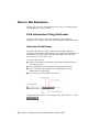
Find Information Using InfoCenter . . . . . . . . . . . . . . . . 10
Overview of InfoCenter . . . . . . . . . . . . . . . . . . . . 10
Search for Information . . . . . . . . . . . . . . . . . . . . 11
Access Subscription Center . . . . . . . . . . . . . . . . . . 12
Use Communication Center . . . . . . . . . . . . . . . . . 14
Save and Access Favorite Topics . . . . . . . . . . . . . . . . 16
Use the Help System . . . . . . . . . . . . . . . . . . . . . 17
Specify InfoCenter Settings . . . . . . . . . . . . . . . . . . 22
Get More Help . . . . . . . . . . . . . . . . . . . . . . . . . . . . 24
Learn the Product . . . . . . . . . . . . . . . . . . . . . . . . . . 25
View the Product Readme . . . . . . . . . . . . . . . . . . . . . . 26
Join the Customer Involvement Program . . . . . . . . . . . . . 27
Chapter 2
Installation . . . . . . . . . . . . . . . . . . . . . . . . . . . . . 29
Quick Start to Stand-Alone Installation . . . . . . . . . . . . .
Prepare for Installation . . . . . . . . . . . . . . . . . .
System Requirements for Stand-Alone Installation .
Install Microsoft .Net Framework 4.0 . . . . . . . .
Understand Administrative Permission
Requirements . . . . . . . . . . . . . . . . . . .
.
.
.
.
.
.
.
.
.
.
.
.
.
.
.
.
. 29
. 29
. 30
. 31
. . . . . 32
iii
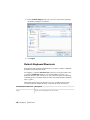
Locate Your Autodesk Navisworks Serial Number and
Product Key . . . . . . . . . . . . . . . . . . . . . . .
Avoid Data Loss During Installation . . . . . . . . . . .
Choose a Language . . . . . . . . . . . . . . . . . . . .
Configuration . . . . . . . . . . . . . . . . . . . . . . .
Install Multiple or Bundled Products . . . . . . . . . . .
Install and Run Autodesk Navisworks Simulate 2012 . . . . .
Install Autodesk Navisworks . . . . . . . . . . . . . . .
Launch Autodesk Navisworks . . . . . . . . . . . . . . .
How to Launch Autodesk Navisworks in Another
Language . . . . . . . . . . . . . . . . . . . . . . . .
Add or Remove Features . . . . . . . . . . . . . . . . .
Repair Autodesk Navisworks Simulate 2012 . . . . . . .
Uninstall Autodesk Navisworks Simulate 2012 . . . . . .
Move to Autodesk Navisworks from a Previous Release . . . .
Install Autodesk Navisworks for Multiple Users . . . . . . . . . . .
Quick Start to Network Administration and Deployment . . .
Deployment Preparation . . . . . . . . . . . . . . . . .
Set Up Network Tools and Your License Server . . . . . .
Distribute the Program . . . . . . . . . . . . . . . . . .
Distribute an Autodesk Navisworks Product . . . . . . .
Set Up a Deployment . . . . . . . . . . . . . . . . . . . . . .
Preliminary Tasks for a Network Deployment . . . . . .
Choose a Language . . . . . . . . . . . . . . . . . . . .
Your Deployment Choices . . . . . . . . . . . . . . . .
Create a Deployment . . . . . . . . . . . . . . . . . . .
Modify a Deployment (optional) . . . . . . . . . . . . .
Point Users to the Administrative Image . . . . . . . . .
Uninstall an Autodesk Product . . . . . . . . . . . . . .
Installation Troubleshooting . . . . . . . . . . . . . . . . . . . . .
General Installation Issues . . . . . . . . . . . . . . . . . . .
How can I check my graphics card driver to see if it needs
to be updated? . . . . . . . . . . . . . . . . . . . . . .
How do I switch my license from stand-alone to network
or network to stand-alone? . . . . . . . . . . . . . . .
When performing a Typical installation, what gets
installed? . . . . . . . . . . . . . . . . . . . . . . . .
Why should I specify the Project Folder and Site
Folder? . . . . . . . . . . . . . . . . . . . . . . . . . .
How do I share the Autodesk Navisworks settings on a
site and project basis? . . . . . . . . . . . . . . . . . .
How do I change which exporter plugins are
installed? . . . . . . . . . . . . . . . . . . . . . . . .
How do I register and activate Autodesk Navisworks? . .
When should I reinstall the product instead of repairing
it? . . . . . . . . . . . . . . . . . . . . . . . . . . . .
iv | Contents
.
.
.
.
.
.
.
.
. 32
. 33
. 33
. 34
. 36
. 36
. 37
. 39
.
.
.
.
.
.
.
.
.
.
.
.
.
.
.
.
.
.
.
.
.
. 40
. 41
. 42
. 42
. 43
. 44
. 44
. 44
. 50
. 52
. 54
. 54
. 55
. 56
. 57
. 65
. 69
. 70
. 70
. 71
. 71
. . 71
. . 72
. . 72
. . 73
. . 73
. . 75
. . 75
. . 76
When I uninstall my software, what files are left on my
system? . . . . . . . . . . . . . . . . . . . . . . . . .
Deployment Issues . . . . . . . . . . . . . . . . . . . . . . .
Is there a checklist I can refer to when performing a
deployment? . . . . . . . . . . . . . . . . . . . . . .
Where should deployments be located? . . . . . . . . .
Where can I check if service packs are available for my
software? . . . . . . . . . . . . . . . . . . . . . . . . .
How do I choose between 32-bit and 64-bit
deployments? . . . . . . . . . . . . . . . . . . . . . .
What are information channels? . . . . . . . . . . . . .
What are additional deployment configuration
options? . . . . . . . . . . . . . . . . . . . . . . . . .
Licensing Issues . . . . . . . . . . . . . . . . . . . . . . . . .
What is the difference between a stand-alone license and
a network license? . . . . . . . . . . . . . . . . . . . .
What is the benefit to using a network licensed version
of the software? . . . . . . . . . . . . . . . . . . . . .
What is Internet Explorer used for? . . . . . . . . . . . .
Networking Issues . . . . . . . . . . . . . . . . . . . . . . . .
Where do I find my server name? . . . . . . . . . . . .
If I choose to create a log file, what kind of information
does the log file contain? . . . . . . . . . . . . . . . .
What is an administrative image (MSI) file? . . . . . . .
What is the impact of selecting all products to be included
in the administrative image? . . . . . . . . . . . . . .
How should I configure a network license server for a
firewall . . . . . . . . . . . . . . . . . . . . . . . . . .
Uninstall and Maintenance Issues . . . . . . . . . . . . . . .
When adding or removing features, how can I tell what
features get installed by default? . . . . . . . . . . . .
Is it possible to change the installation folder when adding
or removing features? . . . . . . . . . . . . . . . . . .
When should I reinstall the product instead of a
repair? . . . . . . . . . . . . . . . . . . . . . . . . . .
When I uninstall my software, what files are left on my
system? . . . . . . . . . . . . . . . . . . . . . . . . .
Chapter 3
. . 77
. . 77
. . 77
. . 77
. . 78
. . 78
. . 78
. . 79
. . 80
. . 80
.
.
.
.
. 81
. 81
. 81
. 81
. . 82
. . 82
. . 82
. . 83
. . 83
. . 83
. . 83
. . 84
. . 84
Quick Start . . . . . . . . . . . . . . . . . . . . . . . . . . . . . 85
Start and Quit Autodesk Navisworks . . . . . . . . . . . . .
Automatically Save and Recover Autodesk Navisworks Files .
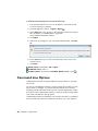
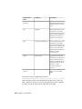
Command Line Options . . . . . . . . . . . . . . . . . . .
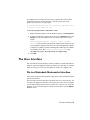
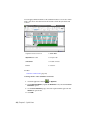
The User Interface . . . . . . . . . . . . . . . . . . . . . . .
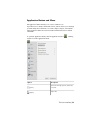
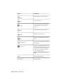
Parts of Autodesk Navisworks Interface . . . . . . . . .
Application Button and Menu . . . . . . . . . .
Quick Access Toolbar . . . . . . . . . . . . . . .
.
.
.
.
.
.
.
.
.
.
.
.
.
.
.
.
.
.
.
.
.
.
.
.
.
.
.
.
.
.
.
.
.
.
.
. 85
. 86
. 88
. 91
. 91
. 93
. 96
Contents | v
Ribbon . . . . . . . . . . . . . . . . . . . . . . . . . . . . . 98
Tooltips . . . . . . . . . . . . . . . . . . . . . . . . . . . . 107
Keytips . . . . . . . . . . . . . . . . . . . . . . . . . . . . 107
Navigation Tools . . . . . . . . . . . . . . . . . . . . . . . 108
The Classic User Interface . . . . . . . . . . . . . . . . . . 108
Scene View . . . . . . . . . . . . . . . . . . . . . . . . . . 129
Dockable Windows . . . . . . . . . . . . . . . . . . . . . 132
Status Bar . . . . . . . . . . . . . . . . . . . . . . . . . . . 138
Undo/Redo Commands . . . . . . . . . . . . . . . . . . . . . . 139
Autodesk Navisworks Workspaces . . . . . . . . . . . . . . . . . 140
Default Keyboard Shortcuts . . . . . . . . . . . . . . . . . . . . 142
Navigation with the Wheel Button . . . . . . . . . . . . . . . . . . . 147
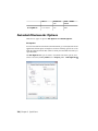
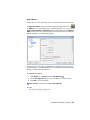
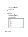
Autodesk Navisworks Options . . . . . . . . . . . . . . . . . . . . . . 150
Location Options . . . . . . . . . . . . . . . . . . . . . . . . . . . . . 154
Graphics System . . . . . . . . . . . . . . . . . . . . . . . . . . . . . 155
Display Units . . . . . . . . . . . . . . . . . . . . . . . . . . . . . . . 157
Profiles . . . . . . . . . . . . . . . . . . . . . . . . . . . . . . . . . . 158
Search Directories . . . . . . . . . . . . . . . . . . . . . . . . . . . . 159
Gizmos . . . . . . . . . . . . . . . . . . . . . . . . . . . . . . . . . . 160
Chapter 4
Work with Files . . . . . . . . . . . . . . . . . . . . . . . . . . 163
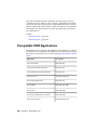
Native File Formats . . . . . . . . . . . . .
Compatible CAD Applications . . . . . . .
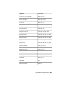
Supported CAD File Formats . . . . .
Supported Laser Scan File Formats . .
Use File Readers . . . . . . . . . . . . . .
3DS File Reader . . . . . . . . . . . .
ASCII Laser Scan File Reader . . . . .
Bentley AutoPLANT File Reader . . .
CIS/2 File Reader . . . . . . . . . . .
DWG/DXF File Reader . . . . . . . .
Overview of Object Enablers .
DWF/DWFx File Reader . . . . . . .
DGN File Reader . . . . . . . . . . .
Faro Scan File Reader . . . . . . . . .
FBX File Reader . . . . . . . . . . . .
IFC File Reader . . . . . . . . . . . .
IGES File Reader . . . . . . . . . . .
Inventor File Reader . . . . . . . . .
JTOpen File Reader . . . . . . . . . .
Leica Scan File Reader . . . . . . . .
MAN File Reader . . . . . . . . . . .
Parasolid File Reader . . . . . . . . .
PDS File Reader . . . . . . . . . . . .
Pro/ENGINEER File Reader . . . . . .
Riegl Scan File Reader . . . . . . . .
vi | Contents
.
.
.
.
.
.
.
.
.
.
.
.
.
.
.
.
.
.
.
.
.
.
.
.
.
.
.
.
.
.
.
.
.
.
.
.
.
.
.
.
.
.
.
.
.
.
.
.
.
.
.
.
.
.
.
.
.
.
.
.
.
.
.
.
.
.
.
.
.
.
.
.
.
.
.
.
.
.
.
.
.
.
.
.
.
.
.
.
.
.
.
.
.
.
.
.
.
.
.
.
.
.
.
.
.
.
.
.
.
.
.
.
.
.
.
.
.
.
.
.
.
.
.
.
.
.
.
.
.
.
.
.
.
.
.
.
.
.
.
.
.
.
.
.
.
.
.
.
.
.
.
.
.
.
.
.
.
.
.
.
.
.
.
.
.
.
.
.
.
.
.
.
.
.
.
.
.
.
.
.
.
.
.
.
.
.
.
.
.
.
.
.
.
.
.
.
.
.
.
.
.
.
.
.
.
.
.
.
.
.
.
.
.
.
.
.
.
.
.
.
.
.
.
.
.
.
.
.
.
.
.
.
.
.
.
.
.
.
.
.
.
.
.
.
.
.
.
.
.
.
.
.
.
.
.
.
.
.
.
.
.
.
.
.
.
.
.
.
.
.
.
.
.
.
.
.
.
.
.
.
.
.
.
.
.
.
.
.
.
.
.
.
.
.
.
.
.
.
.
.
.
.
.
.
.
.
.
.
.
.
.
.
.
.
.
.
.
.
.
.
.
.
.
.
.
.
.
.
.
.
.
.
.
.
.
.
.
.
.
.
.
.
.
.
.
.
.
.
.
.
. 163
. 164
. 168
. 169
. 170
. 170
. 171
. 172
. 172
. 175
. 176
. 178
. 179
. 180
. 180
. 181
. 182
. 183
. 183
. 184
. 185
. 186
. 186
. 187
. 187
RVM File Reader . . . . . . . . . . . . . . . . . . . . .
SAT File Reader . . . . . . . . . . . . . . . . . . . . . .
SketchUp SKP File Reader . . . . . . . . . . . . . . . .
STEP File Reader . . . . . . . . . . . . . . . . . . . . .
STL File Reader . . . . . . . . . . . . . . . . . . . . . .
VRML File Reader . . . . . . . . . . . . . . . . . . . .
Z+F Scan File Reader . . . . . . . . . . . . . . . . . . .
Use File Exporters . . . . . . . . . . . . . . . . . . . . . . .
AutoCAD File Exporter . . . . . . . . . . . . . . . . . .
Add the ARX Plugin . . . . . . . . . . . . . . . .
Use the ARX Plugin . . . . . . . . . . . . . . . .
CAD Preview . . . . . . . . . . . . . . . . . . . .
Revit File Exporter . . . . . . . . . . . . . . . . . . . .
MicroStation File Exporter . . . . . . . . . . . . . . . .
Load the MDL Plugin . . . . . . . . . . . . . . .
Export Files from the Key-In Command Line . . .
Export Files from the Command Line . . . . . . .
Customize the DGN File Exporter Options . . . .
Viz and Max File Exporter . . . . . . . . . . . . . . . .
ArchiCAD File Exporter . . . . . . . . . . . . . . . . .
Manage Files . . . . . . . . . . . . . . . . . . . . . . . . . .
Open Files . . . . . . . . . . . . . . . . . . . . . . . .
Create Files . . . . . . . . . . . . . . . . . . . . . . . .
Save and Rename Files . . . . . . . . . . . . . . . . . .
2D and Multi-Sheet Files . . . . . . . . . . . . . . . . .
Add Sheets/Models to the Currently Opened File .
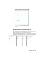
Project Browser Window . . . . . . . . . . . . . .
Work with 2D and Multi-Sheet Files . . . . . . .
Add Geometry and Metadata to the Current
Sheet/Model . . . . . . . . . . . . . . . . . . .
Complex Datasets . . . . . . . . . . . . . . . . . . . .
Append Geometry and Metadata to the Current
Scene . . . . . . . . . . . . . . . . . . . . . . .
Delete Files . . . . . . . . . . . . . . . . . . . . .
Adjust Units and Transform . . . . . . . . . . . .
Refresh Files . . . . . . . . . . . . . . . . . . . . . . .
Merge Files . . . . . . . . . . . . . . . . . . . . . . . .
Email Files . . . . . . . . . . . . . . . . . . . . . . . .
Receive Files . . . . . . . . . . . . . . . . . . . . . . .
Batch Utility . . . . . . . . . . . . . . . . . . . . . . .
Use Batch Utility . . . . . . . . . . . . . . . . . .
Command Line Options for Batch Utility . . . . .
View Scene Statistics . . . . . . . . . . . . . . . . . . . . . .
Chapter 5
.
.
.
.
.
.
.
.
.
.
.
.
.
.
.
.
.
.
.
.
.
.
.
.
.
.
.
.
.
.
.
.
.
.
.
.
.
.
.
.
.
.
.
.
.
.
.
.
.
.
.
.
.
.
.
.
.
.
.
.
.
.
.
.
.
.
.
.
.
.
.
.
.
.
.
.
.
.
.
.
.
.
.
.
.
.
.
.
.
.
.
.
.
.
.
.
.
.
.
.
.
.
.
.
.
.
.
.
.
.
.
.
. 188
. 189
. 189
. 190
. 190
. 190
. 191
. 192
. 192
. 192
. 193
. 195
. 199
. 200
. 201
. 202
. 203
. 204
. 204
. 205
. 208
. 208
. 209
. 209
. 212
. 213
. 213
. 217
. . . . . 218
. . . . . 220
.
.
.
.
.
.
.
.
.
.
.
.
.
.
.
.
.
.
.
.
.
.
.
.
.
.
.
.
.
.
.
.
.
.
.
.
.
.
.
.
.
.
.
.
. 221
. 221
. 222
. 224
. 224
. 226
. 226
. 227
. 227
. 235
. 237
Explore Your Model . . . . . . . . . . . . . . . . . . . . . . . 239
Navigate a Scene . . . . . . . . . . . . . . . . . . . . . . . . . . . . . 239
Contents | vii
Orientation in a 3D Workspace . . . . . . . . . . . . . . . . . . 240
Product-Specific Navigation Tools . . . . . . . . . . . . . . . . . 241
Navigation Bar Tools . . . . . . . . . . . . . . . . . . . . . 242
SteeringWheels Tools . . . . . . . . . . . . . . . . . . . . 247
Classic Navigation Modes and Tools . . . . . . . . . . . . 264
ViewCube . . . . . . . . . . . . . . . . . . . . . . . . . . . . . 273
Overview of ViewCube . . . . . . . . . . . . . . . . . . . 273
ViewCube Menu . . . . . . . . . . . . . . . . . . . . . . . 276
Reorient the View of a Model with ViewCube . . . . . . . 277
Set the View Projection Mode . . . . . . . . . . . . . . . . 281
Home View . . . . . . . . . . . . . . . . . . . . . . . . . . 282
Examine Individual Objects with ViewCube . . . . . . . . 283
Navigation Bar . . . . . . . . . . . . . . . . . . . . . . . . . . . 283
Overview of Navigation Bar . . . . . . . . . . . . . . . . . 284
Reposition and Reorient the Navigation Bar . . . . . . . . 285
Control the Display of Navigation Tools on the Navigation
Bar . . . . . . . . . . . . . . . . . . . . . . . . . . . . . 286
SteeringWheels . . . . . . . . . . . . . . . . . . . . . . . . . . . 287
Overview of SteeringWheels . . . . . . . . . . . . . . . . . 287
Wheel Menu . . . . . . . . . . . . . . . . . . . . . . . . . 291
View Object Wheels . . . . . . . . . . . . . . . . . . . . . 292
Tour Building Wheels . . . . . . . . . . . . . . . . . . . . 294
Full Navigation Wheels . . . . . . . . . . . . . . . . . . . 296
2D Navigation Wheel . . . . . . . . . . . . . . . . . . . . 298
3Dconnexion 3D Mouse . . . . . . . . . . . . . . . . . . . . . . 298
Camera . . . . . . . . . . . . . . . . . . . . . . . . . . . . . . . 301
Set Camera Projection . . . . . . . . . . . . . . . . . . . . 301
Control the Field of View . . . . . . . . . . . . . . . . . . 302
Position and Focus Camera . . . . . . . . . . . . . . . . . 302
Navigation Aids . . . . . . . . . . . . . . . . . . . . . . . . . . 306
Head-Up Display . . . . . . . . . . . . . . . . . . . . . . . 306
Reference Views . . . . . . . . . . . . . . . . . . . . . . . 307
Focus . . . . . . . . . . . . . . . . . . . . . . . . . . . . . . . . 310
Hold . . . . . . . . . . . . . . . . . . . . . . . . . . . . . . . . 310
Control the Realism of Your Navigation . . . . . . . . . . . . . . . . . 311
Gravity . . . . . . . . . . . . . . . . . . . . . . . . . . . . . . . 311
Crouching . . . . . . . . . . . . . . . . . . . . . . . . . . . . . 311
Collision . . . . . . . . . . . . . . . . . . . . . . . . . . . . . . 312
Third Person View . . . . . . . . . . . . . . . . . . . . . . . . . 313
Chapter 6
Control Model Appearance and Render Quality . . . . . . . . 317
Control Model Appearance .
Select Render Mode . .
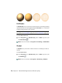
Full Render . . . .
Shaded . . . . . .
Wireframe . . . .
viii | Contents
.
.
.
.
.
.
.
.
.
.
.
.
.
.
.
.
.
.
.
.
.
.
.
.
.
.
.
.
.
.
.
.
.
.
.
.
.
.
.
.
.
.
.
.
.
.
.
.
.
.
.
.
.
.
.
.
.
.
.
.
.
.
.
.
.
.
.
.
.
.
.
.
.
.
.
.
.
.
.
.
.
.
.
.
.
.
.
.
.
.
.
.
.
.
.
.
.
.
.
.
.
.
.
.
.
. 317
. 317
. 318
. 318
. 319
Hidden Line . . . . . . . . . . . . . . . . .
Add Lighting . . . . . . . . . . . . . . . . . . . .
Full Lights . . . . . . . . . . . . . . . . . .
Scene Lights . . . . . . . . . . . . . . . . .
Head Light . . . . . . . . . . . . . . . . . .
No Lights . . . . . . . . . . . . . . . . . . .
Select Background Effect . . . . . . . . . . . . . .
Adjust Displaying of Primitives . . . . . . . . . .
Surfaces . . . . . . . . . . . . . . . . . . .
Lines . . . . . . . . . . . . . . . . . . . . .
Points . . . . . . . . . . . . . . . . . . . .
Snap Points . . . . . . . . . . . . . . . . .
Text . . . . . . . . . . . . . . . . . . . . . .
Control Render Quality . . . . . . . . . . . . . . . . .
Use Culling . . . . . . . . . . . . . . . . . . . . .
Make Objects Required . . . . . . . . . . .
Control Rendering of Objects . . . . . . . . . . .
Adjust Scene Rendering During Navigation .
Accelerate Display Performance . . . . . . .
Adjust Presenter Materials . . . . . . . . . . . . .
Stereo Rendering . . . . . . . . . . . . . . . . . .
Chapter 7
.
.
.
.
.
.
.
.
.
.
.
.
.
.
.
.
.
.
.
.
.
.
.
.
.
.
.
.
.
.
.
.
.
.
.
.
.
.
.
.
.
.
.
.
.
.
.
.
.
.
.
.
.
.
.
.
.
.
.
.
.
.
.
.
.
.
.
.
.
.
.
.
.
.
.
.
.
.
.
.
.
.
.
.
.
.
.
.
.
.
.
.
.
.
.
.
.
.
.
.
.
.
.
.
.
.
.
.
.
.
.
.
.
.
.
.
.
.
.
.
.
.
.
.
.
.
.
.
.
.
.
.
.
.
.
.
.
.
.
.
.
.
.
.
.
.
.
. 319
. 319
. 320
. 320
. 321
. 322
. 323
. 325
. 325
. 325
. 326
. 326
. 327
. 327
. 327
. 330
. 331
. 331
. 333
. 334
. 334
Review Your Model . . . . . . . . . . . . . . . . . . . . . . . 337
Select Objects . . . . . . . . . . . . . . . . . . . . . . . . . .
Interactive Geometry Selection . . . . . . . . . . . . .
Selection Tree Window . . . . . . . . . . . . . .
Selection Tools . . . . . . . . . . . . . . . . . . .
Selection Commands . . . . . . . . . . . . . . .
Set Selection Resolution . . . . . . . . . . . . . . . . .
Set Highlighting Method . . . . . . . . . . . . . . . .
Hide Objects . . . . . . . . . . . . . . . . . . . . . . .
Find Objects . . . . . . . . . . . . . . . . . . . . . . . . . .
Find Items Window . . . . . . . . . . . . . . . . . . .
Quick Find . . . . . . . . . . . . . . . . . . . . . . . .
Find All Sheets and Models Containing the Selected Object .
Find Items in Other Sheets and Models Window . . . .
Create and Use Sets of Objects . . . . . . . . . . . . . . . .
Sets Window . . . . . . . . . . . . . . . . . . . . . . .
Create and Manage Selection and Search Sets . . . . . .
Compare Objects . . . . . . . . . . . . . . . . . . . . . . . .
Object Properties . . . . . . . . . . . . . . . . . . . . . . . .
Properties Window . . . . . . . . . . . . . . . . . . . .
Custom Properties . . . . . . . . . . . . . . . . . . . .
External Database Links . . . . . . . . . . . . . . . . .
Manipulate Object Attributes . . . . . . . . . . . . . . . . .
Transform Objects . . . . . . . . . . . . . . . . . . . .
.
.
.
.
.
.
.
.
.
.
.
.
.
.
.
.
.
.
.
.
.
.
.
.
.
.
.
.
.
.
.
.
.
.
.
.
.
.
.
.
.
.
.
.
.
.
.
.
.
.
.
.
.
.
.
.
.
.
.
.
.
.
.
.
.
.
.
.
.
.
.
.
.
.
.
.
.
.
.
.
.
.
.
.
.
.
.
.
.
.
.
.
. 337
. 337
. 338
. 341
. 343
. 345
. 346
. 348
. 349
. 349
. 355
. 356
. 357
. 360
. 360
. 362
. 365
. 367
. 367
. 369
. 371
. 382
. 383
Contents | ix
Change Object Appearance . . . .
Snapping . . . . . . . . . . . . . .
Reset to Original Values . . . . . .
Measure Tools . . . . . . . . . . . . . .
Measure Tools Window . . . . . .
Measuring . . . . . . . . . . . . .
Comments, Redlines, and Tags . . . . .
Use Comments, Redlines, and Tags
Comments Window . . . . .
Redline Tools Panel . . . . .
View Redlines and Tags . . .
Tags Panel . . . . . . . . . .
Edit Comments and Tags . .
Edit Redlines . . . . . . . . .
Find Comments and Tags . . . . .
Find Comments Window . .
Quick Find Comments . . . .
Find Tags . . . . . . . . . . .
Manage Comment and Tag IDs . .
Links . . . . . . . . . . . . . . . . . . .
Link Categories . . . . . . . . . . .
Display Links . . . . . . . . . . . .
Customize Links . . . . . . . . . .
Add Links . . . . . . . . . . . . .
Find and Follow Links . . . . . . .
Manage Links . . . . . . . . . . .
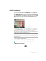
Quick Properties . . . . . . . . . . . . .
SwitchBack . . . . . . . . . . . . . . . .
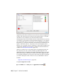
Appearance Profiler . . . . . . . . . . .
Chapter 8
.
.
.
.
.
.
.
.
.
.
.
.
.
.
.
.
.
.
.
.
.
.
.
.
.
.
.
.
.
.
.
.
.
.
.
.
.
.
.
.
.
.
.
.
.
.
.
.
.
.
.
.
.
.
.
.
.
.
.
.
.
.
.
.
.
.
.
.
.
.
.
.
.
.
.
.
.
.
.
.
.
.
.
.
.
.
.
.
.
.
.
.
.
.
.
.
.
.
.
.
.
.
.
.
.
.
.
.
.
.
.
.
.
.
.
.
.
.
.
.
.
.
.
.
.
.
.
.
.
.
.
.
.
.
.
.
.
.
.
.
.
.
.
.
.
.
.
.
.
.
.
.
.
.
.
.
.
.
.
.
.
.
.
.
.
.
.
.
.
.
.
.
.
.
.
.
.
.
.
.
.
.
.
.
.
.
.
.
.
.
.
.
.
.
.
.
.
.
.
.
.
.
.
.
.
.
.
.
.
.
.
.
.
.
.
.
.
.
.
.
.
.
.
.
.
.
.
.
.
.
.
.
.
.
.
.
.
.
.
.
.
.
.
.
.
.
.
.
.
.
.
.
.
.
.
.
.
.
.
.
.
.
.
.
.
.
.
.
.
.
.
.
.
.
.
.
.
.
.
.
.
.
.
.
.
.
.
.
.
.
.
.
.
.
.
.
.
.
.
.
.
.
.
.
.
.
.
.
.
.
.
.
.
.
.
.
.
.
.
.
.
.
.
.
.
.
.
.
.
.
.
.
.
.
.
.
.
.
.
.
.
.
.
.
.
.
.
.
.
.
.
.
.
.
.
.
.
.
.
.
.
.
.
.
.
.
.
.
.
.
.
.
.
.
.
.
.
.
.
.
.
.
.
.
.
.
.
.
.
.
.
.
.
.
.
.
.
.
.
.
.
.
.
.
.
.
. 388
. 389
. 390
. 391
. 391
. 393
. 399
. 399
. 400
. 402
. 409
. 410
. 411
. 412
. 413
. 413
. 417
. 418
. 419
. 420
. 420
. 421
. 422
. 425
. 427
. 428
. 431
. 433
. 435
Use Viewpoints and Sectioning Modes . . . . . . . . . . . . . 439
Create and Modify Viewpoints . . . . . . . . . .
Overview of Viewpoints . . . . . . . . . . .
Saved Viewpoints Window . . . . . . . . .
Save Viewpoints . . . . . . . . . . . . . . .
Recall Viewpoints . . . . . . . . . . . . . .
Organize Viewpoints . . . . . . . . . . . . .
Edit Viewpoints . . . . . . . . . . . . . . .
Default Viewpoint Options . . . . . . . . .
Share Viewpoints . . . . . . . . . . . . . . .
Sectioning . . . . . . . . . . . . . . . . . . . . .
Enable and Use Section Planes . . . . . . . .
Customize Section Plane Alignment .
Move and Rotate Section Planes . . . .
Link Section Planes . . . . . . . . . .
Enable and Use Section Box . . . . . . . . .
x | Contents
.
.
.
.
.
.
.
.
.
.
.
.
.
.
.
.
.
.
.
.
.
.
.
.
.
.
.
.
.
.
.
.
.
.
.
.
.
.
.
.
.
.
.
.
.
.
.
.
.
.
.
.
.
.
.
.
.
.
.
.
.
.
.
.
.
.
.
.
.
.
.
.
.
.
.
.
.
.
.
.
.
.
.
.
.
.
.
.
.
.
.
.
.
.
.
.
.
.
.
.
.
.
.
.
.
.
.
.
.
.
.
.
.
.
.
.
.
.
.
.
.
.
.
.
.
.
.
.
.
.
.
.
.
.
.
.
.
.
.
.
.
.
.
.
.
.
.
.
.
.
.
.
.
.
.
.
.
.
.
.
.
.
.
.
.
.
.
.
.
.
.
.
.
.
.
.
.
.
.
. 439
. 439
. 440
. 445
. 446
. 446
. 447
. 449
. 452
. 453
. 454
. 457
. 459
. 462
. 463
Chapter 9
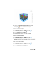
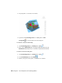
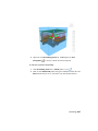
Record and Play Animations . . . . . . . . . . . . . . . . . . 469
Create and Edit Viewpoint Animations . . . . . . . . . . . . . . . . . 469
Play Animations and Scripts . . . . . . . . . . . . . . . . . . . . . . . 473
Share Animations . . . . . . . . . . . . . . . . . . . . . . . . . . . . 475
Chapter 10
Work Within a Team . . . . . . . . . . . . . . . . . . . . . . . 477
Collaborate Panel . . . . . . . . . . . . . . . . . . . . . . . . . . . . 477
Collaboration Session . . . . . . . . . . . . . . . . . . . . . . . . . . 477
Chapter 11
Share Data . . . . . . . . . . . . . . . . . . . . . . . . . . . . 481
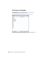
Print . . . . . . . . . . . . . . . . . .
Print Preview . . . . . . . . . . .
Print Setup . . . . . . . . . . . .
Print Current Viewpoint . . . . .
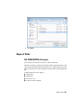
Import Files . . . . . . . . . . . . . .
Search Criteria Files . . . . . . .
Search Set Files . . . . . . . . . .
PDS Display Set Files . . . . . .
PDS Tag Files . . . . . . . . . . .
Viewpoints Files . . . . . . . . .
Export Files . . . . . . . . . . . . . . .
3D DWF/DWFx Format . . . . .
Google Earth KML Format . . . .
Autodesk FBX Format . . . . . .
Export Images and Animations .
Export an Image . . . . . .
Export a Rendered Image .
Export an Animation . . .
Piranesi EPix Format . . . .
Current Search Criteria . . . . .
Search Set Files . . . . . . . . . .
Viewpoints Files . . . . . . . . .
Viewpoints Report . . . . . . . .
TimeLiner CSV . . . . . . . . . .
PDS Tag Files . . . . . . . . . . .
Chapter 12
.
.
.
.
.
.
.
.
.
.
.
.
.
.
.
.
.
.
.
.
.
.
.
.
.
.
.
.
.
.
.
.
.
.
.
.
.
.
.
.
.
.
.
.
.
.
.
.
.
.
.
.
.
.
.
.
.
.
.
.
.
.
.
.
.
.
.
.
.
.
.
.
.
.
.
.
.
.
.
.
.
.
.
.
.
.
.
.
.
.
.
.
.
.
.
.
.
.
.
.
.
.
.
.
.
.
.
.
.
.
.
.
.
.
.
.
.
.
.
.
.
.
.
.
.
.
.
.
.
.
.
.
.
.
.
.
.
.
.
.
.
.
.
.
.
.
.
.
.
.
.
.
.
.
.
.
.
.
.
.
.
.
.
.
.
.
.
.
.
.
.
.
.
.
.
.
.
.
.
.
.
.
.
.
.
.
.
.
.
.
.
.
.
.
.
.
.
.
.
.
.
.
.
.
.
.
.
.
.
.
.
.
.
.
.
.
.
.
.
.
.
.
.
.
.
.
.
.
.
.
.
.
.
.
.
.
.
.
.
.
.
.
.
.
.
.
.
.
.
.
.
.
.
.
.
.
.
.
.
.
.
.
.
.
.
.
.
.
.
.
.
.
.
.
.
.
.
.
.
.
.
.
.
.
.
.
.
.
.
.
.
.
.
.
.
.
.
.
.
.
.
.
.
.
.
.
.
.
.
.
.
.
.
.
.
.
.
.
.
.
.
.
.
.
.
.
.
.
.
.
.
.
.
.
.
.
.
.
.
.
.
.
.
.
.
.
.
.
.
.
.
.
.
.
.
.
.
.
.
.
.
.
.
.
.
.
.
.
.
.
.
.
.
.
.
.
.
.
.
.
.
.
.
.
.
.
.
.
.
.
.
.
.
.
.
.
.
.
.
.
. 481
. 481
. 481
. 482
. 482
. 483
. 483
. 484
. 485
. 486
. 487
. 487
. 488
. 490
. 492
. 492
. 494
. 494
. 495
. 496
. 496
. 496
. 497
. 498
. 498
Animate Objects . . . . . . . . . . . . . . . . . . . . . . . . . 499
Overview of the Animator Tool . . . . .
Animator Window . . . . . . . . .
The Animator Toolbar . . . .
The Animator Tree View . . .
The Animator Timeline View
The Manual Entry Bar . . . .
Scripter Window . . . . . . . . . .
.
.
.
.
.
.
.
.
.
.
.
.
.
.
.
.
.
.
.
.
.
.
.
.
.
.
.
.
.
.
.
.
.
.
.
.
.
.
.
.
.
.
.
.
.
.
.
.
.
.
.
.
.
.
.
.
.
.
.
.
.
.
.
.
.
.
.
.
.
.
.
.
.
.
.
.
.
.
.
.
.
.
.
.
.
.
.
.
.
.
.
.
.
.
.
.
.
.
.
.
.
.
.
.
.
. 500
. 500
. 500
. 502
. 506
. 509
. 511
Contents | xi
The Scripter Tree View . . . . .
The Events View . . . . . . . .
The Actions View . . . . . . .
The Properties View . . . . . .
Create Object Animations . . . . . . . . .
Work with Animation Scenes . . . .
Work with Animation Sets . . . . . .
Add Animation Sets . . . . . .
Update Animation Sets . . . .
Manipulate Geometry Objects .
Work with Cameras . . . . . . . . .
Work with Section Plane Sets . . . .
Work with Keyframes . . . . . . . .
Capture Keyframes . . . . . . .
Edit Keyframes . . . . . . . . .
Play Animation Scenes . . . . . . . .
Add Interactivity . . . . . . . . . . . . . .
Work with Animation Scripts . . . .
Work with Events . . . . . . . . . .
Work with Actions . . . . . . . . . .
Enable Scripting . . . . . . . . . . .
Chapter 13
.
.
.
.
.
.
.
.
.
.
.
.
.
.
.
.
.
.
.
.
.
.
.
.
.
.
.
.
.
.
.
.
.
.
.
.
.
.
.
.
.
.
.
.
.
.
.
.
.
.
.
.
.
.
.
.
.
.
.
.
.
.
.
.
.
.
.
.
.
.
.
.
.
.
.
.
.
.
.
.
.
.
.
.
.
.
.
.
.
.
.
.
.
.
.
.
.
.
.
.
.
.
.
.
.
.
.
.
.
.
.
.
.
.
.
.
.
.
.
.
.
.
.
.
.
.
.
.
.
.
.
.
.
.
.
.
.
.
.
.
.
.
.
.
.
.
.
.
.
.
.
.
.
.
.
.
.
.
.
.
.
.
.
.
.
.
.
.
.
.
.
.
.
.
.
.
.
.
.
.
.
.
.
.
.
.
.
.
.
.
.
.
.
.
.
.
.
.
.
.
.
.
.
.
.
.
.
.
.
.
.
.
.
.
.
.
.
.
.
.
.
.
.
.
.
.
.
.
.
.
.
.
.
.
.
.
.
.
.
.
.
.
.
.
.
.
.
.
.
.
.
.
.
.
.
.
.
.
.
.
.
.
.
.
.
.
.
.
.
.
.
.
.
. 511
. 513
. 515
. 516
. 523
. 524
. 527
. 527
. 528
. 529
. 532
. 533
. 535
. 535
. 536
. 536
. 538
. 538
. 540
. 542
. 544
Create Photorealistic Visualizations . . . . . . . . . . . . . . . 545
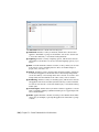
Overview of the Presenter Tool . . . . . . . .
Presenter Window . . . . . . . . . . . .
Use the Presenter Archives . . . . . . . .
Photo-Realistic Scene Rendering . . . . . . . .
Use Presenter Materials . . . . . . . . . . . .
Materials Tab . . . . . . . . . . . . . . .
Apply and Remove Presenter Materials .
Organize and Manage Materials . . . . .
Edit Presenter Materials . . . . . . . . .
Advanced Materials . . . . . . . . . . .
Use Presenter Lights . . . . . . . . . . . . . .
Lighting Tab . . . . . . . . . . . . . . .
Add and Position Lights . . . . . . . . .
Organize and Manage Lights . . . . . .
Edit Lights . . . . . . . . . . . . . . . .
Shadow Casting . . . . . . . . . . . . .
Advanced Lighting . . . . . . . . . . . .
Soft Shadows . . . . . . . . . . . .
Physically Accurate Lights . . . . .
Volumetric Lights . . . . . . . . .
Image-based Lighting . . . . . . .
Use Presenter RPCs . . . . . . . . . . . . . . .
RPC Tab . . . . . . . . . . . . . . . . .
xii | Contents
.
.
.
.
.
.
.
.
.
.
.
.
.
.
.
.
.
.
.
.
.
.
.
.
.
.
.
.
.
.
.
.
.
.
.
.
.
.
.
.
.
.
.
.
.
.
.
.
.
.
.
.
.
.
.
.
.
.
.
.
.
.
.
.
.
.
.
.
.
.
.
.
.
.
.
.
.
.
.
.
.
.
.
.
.
.
.
.
.
.
.
.
.
.
.
.
.
.
.
.
.
.
.
.
.
.
.
.
.
.
.
.
.
.
.
.
.
.
.
.
.
.
.
.
.
.
.
.
.
.
.
.
.
.
.
.
.
.
.
.
.
.
.
.
.
.
.
.
.
.
.
.
.
.
.
.
.
.
.
.
.
.
.
.
.
.
.
.
.
.
.
.
.
.
.
.
.
.
.
.
.
.
.
.
.
.
.
.
.
.
.
.
.
.
.
.
.
.
.
.
.
.
.
.
.
.
.
.
.
.
.
.
.
.
.
.
.
.
.
.
.
.
.
.
.
.
.
.
.
.
.
.
.
.
.
.
.
.
.
.
.
.
.
.
.
.
.
.
.
.
.
.
.
.
.
.
.
.
.
.
.
.
.
.
.
.
.
.
.
.
.
.
.
.
.
.
.
.
.
.
.
.
.
.
.
.
.
.
.
.
.
.
.
.
.
.
.
. 545
. 545
. 547
. 549
. 552
. 552
. 552
. 555
. 557
. 561
. 564
. 564
. 565
. 567
. 569
. 572
. 573
. 574
. 574
. 575
. 576
. 579
. 579
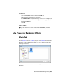
Use Presenter Rendering Effects . . .
Effects Tab . . . . . . . . . . .
Background Effects . . . . . . .
Foreground Effects . . . . . . .
Use Presenter Rendering Styles . . .
Rendering Tab . . . . . . . . .
Rendering Styles . . . . . . . .
Predefined Rendering Styles . .
Auto Exposure . . . . . . . . .
Use Presenter Texture Space . . . . .
Use Presenter Rules . . . . . . . . . .
Rules Tab . . . . . . . . . . . .
Predefined Rules . . . . . . . .
Custom Rules . . . . . . . . .
The Presenter Rules Example .
Chapter 14
.
.
.
.
.
.
.
.
.
.
.
.
.
.
.
.
.
.
.
.
.
.
.
.
.
.
.
.
.
.
.
.
.
.
.
.
.
.
.
.
.
.
.
.
.
.
.
.
.
.
.
.
.
.
.
.
.
.
.
.
.
.
.
.
.
.
.
.
.
.
.
.
.
.
.
.
.
.
.
.
.
.
.
.
.
.
.
.
.
.
.
.
.
.
.
.
.
.
.
.
.
.
.
.
.
.
.
.
.
.
.
.
.
.
.
.
.
.
.
.
.
.
.
.
.
.
.
.
.
.
.
.
.
.
.
.
.
.
.
.
.
.
.
.
.
.
.
.
.
.
.
.
.
.
.
.
.
.
.
.
.
.
.
.
.
.
.
.
.
.
.
.
.
.
.
.
.
.
.
.
.
.
.
.
.
.
.
.
.
.
.
.
.
.
.
.
.
.
.
.
.
.
.
.
.
.
.
.
.
.
.
.
.
.
.
.
.
.
.
.
.
.
.
.
.
.
.
.
.
.
.
.
.
.
.
.
.
.
.
.
.
.
.
.
.
.
.
.
.
.
.
.
.
.
.
. 583
. 583
. 584
. 589
. 590
. 590
. 591
. 592
. 594
. 594
. 596
. 596
. 597
. 598
. 600
Simulate Construction Scheduling . . . . . . . . . . . . . . . 603
Overview of TimeLiner Tool . . . . . . . . . . . . . . . . . .
TimeLiner Window . . . . . . . . . . . . . . . . . . .
Tasks Tab . . . . . . . . . . . . . . . . . . . . . .
Data Sources Tab . . . . . . . . . . . . . . . . . .
Configure Tab . . . . . . . . . . . . . . . . . . .
Simulate Tab . . . . . . . . . . . . . . . . . . . .
Choose TimeLiner Columns Dialog Box . . . . . . . .
TimeLiner Rules Dialog Box . . . . . . . . . . . . . . .
Field Selector Dialog Box . . . . . . . . . . . . . . . .
Refresh from Data Source Dialog Box . . . . . . . . . .
Simulation Settings Dialog Box . . . . . . . . . . . . .
Overlay Text Dialog Box . . . . . . . . . . . . . . . . .
Appearance Definitions Dialog Box . . . . . . . . . . .
Get Started . . . . . . . . . . . . . . . . . . . . . . . .
TimeLiner Tasks . . . . . . . . . . . . . . . . . . . . . . . .
Create Tasks . . . . . . . . . . . . . . . . . . . . . . .
Edit Tasks . . . . . . . . . . . . . . . . . . . . . . . . .
Use Gantt Charts . . . . . . . . . . . . . . . . . . . . .
Attach Tasks to Geometry . . . . . . . . . . . . . . . .
Attach Tasks Manually . . . . . . . . . . . . . . .
Use Rules to Attach Tasks . . . . . . . . . . . . .
Validate Project Schedule . . . . . . . . . . . . . . . .
Link to External Project Files . . . . . . . . . . . . . . . . .
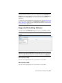
Supported Scheduling Software . . . . . . . . . . . . .
CSV Support . . . . . . . . . . . . . . . . . . . . . . .
Add and Manage Data Sources . . . . . . . . . . . . . .
Import Data from an External Project Schedule .
Edit a Data Source . . . . . . . . . . . . . . . . .
Delete a Data Source . . . . . . . . . . . . . . . .
.
.
.
.
.
.
.
.
.
.
.
.
.
.
.
.
.
.
.
.
.
.
.
.
.
.
.
.
.
.
.
.
.
.
.
.
.
.
.
.
.
.
.
.
.
.
.
.
.
.
.
.
.
.
.
.
.
.
.
.
.
.
.
.
.
.
.
.
.
.
.
.
.
.
.
.
.
.
.
.
.
.
.
.
.
.
.
.
.
.
.
.
.
.
.
.
.
.
.
.
.
.
.
.
.
.
.
.
.
.
.
.
.
.
.
.
. 603
. 604
. 605
. 609
. 611
. 613
. 615
. 615
. 616
. 620
. 620
. 626
. 628
. 629
. 633
. 635
. 637
. 639
. 640
. 641
. 642
. 645
. 646
. 647
. 650
. 650
. 650
. 654
. 654
Contents | xiii
Build Tasks from Data Sources . . . .
Synchronize Tasks with Project Changes .
4D Simulation . . . . . . . . . . . . . . . . . .
Play Simulations . . . . . . . . . . . . . .
Configure Simulations . . . . . . . . . . .
Simulation Playback . . . . . . . . .
Simulation Appearance . . . . . . .
Export . . . . . . . . . . . . . . . . . . . . . .
Add Animation . . . . . . . . . . . . . . . . . .
Overview . . . . . . . . . . . . . . . . . .
Add Animation to an Entire Schedule . . .
Add Animation to Tasks . . . . . . . . . .
Add Scripts to Tasks . . . . . . . . . . . .
Chapter 15
.
.
.
.
.
.
.
.
.
.
.
.
.
.
.
.
.
.
.
.
.
.
.
.
.
.
.
.
.
.
.
.
.
.
.
.
.
.
.
.
.
.
.
.
.
.
.
.
.
.
.
.
.
.
.
.
.
.
.
.
.
.
.
.
.
.
.
.
.
.
.
.
.
.
.
.
.
.
.
.
.
.
.
.
.
.
.
.
.
.
.
.
.
.
.
.
.
.
.
.
.
.
.
.
.
.
.
.
.
.
.
.
.
.
.
.
.
. 655
. 655
. 656
. 656
. 657
. 657
. 657
. 660
. 660
. 660
. 661
. 663
. 664
.
.
.
.
.
.
.
.
.
.
.
.
.
.
.
.
.
.
.
.
.
.
.
.
.
.
.
.
.
.
.
.
.
.
.
.
.
.
.
.
.
.
.
.
.
.
.
.
.
.
.
.
.
.
.
.
.
.
.
.
.
.
.
.
.
.
.
.
.
.
.
.
.
.
.
.
.
.
.
.
.
.
.
.
.
.
.
.
.
.
.
.
.
.
.
.
.
.
.
.
.
.
.
.
.
.
.
.
.
.
.
.
.
.
.
.
.
.
.
.
.
.
.
.
.
.
.
.
.
.
.
.
.
.
.
.
.
.
.
.
.
.
.
.
.
.
.
.
.
.
.
.
.
.
.
.
.
.
.
.
.
.
.
.
.
.
.
.
.
.
.
.
.
.
.
.
.
.
.
.
.
.
.
.
.
.
.
.
.
.
.
.
.
.
.
.
.
.
.
.
.
.
.
.
.
.
.
.
.
.
.
.
.
.
.
.
.
.
.
.
.
.
.
.
.
.
.
.
.
.
.
.
.
.
.
.
.
.
.
.
.
.
.
.
.
.
.
.
.
.
.
.
.
.
.
. 665
. 666
. 666
. 667
. 667
. 669
. 670
. 671
. 671
. 672
. 673
. 673
. 674
. 675
. 675
. 676
. 676
Reference . . . . . . . . . . . . . . . . . . . . . . . . . . . . . 679
Animation Export Dialog Box . . . . .
Appearance Profiler Dialog Box . . . .
Background Settings Dialog Box . . . .
Collision Dialog Box . . . . . . . . . .
Convert Object Properties Dialog Box .
Culling Options Dialog Box . . . . . .
Customize Dialog Box . . . . . . . . .
Toolbars Tab . . . . . . . . . . .
Commands Tab . . . . . . . . .
Options Tab . . . . . . . . . . .
Default Collision Dialog Box . . . . .
xiv | Contents
.
.
.
.
.
.
.
.
.
.
.
.
.
Use the Autodesk Vault Add-In . . . . . . . . . . . . . . . . . 665
About the Autodesk Vault Add-In . . . .
Launching the Vault Application . . . .
Log into a Vault . . . . . . . . . . . . .
Log out of a Vault . . . . . . . . . . . .
Understanding the Working Folder . . .
Check Out a File . . . . . . . . . . . . .
Get Files from a Vault . . . . . . . . . .
Refresh a Vaulted File . . . . . . . . . .
Check a File into a Vault . . . . . . . . .
Undo File Check Out . . . . . . . . . . .
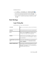
Vault Settings . . . . . . . . . . . . . . .
Log In Dialog Box . . . . . . . . .
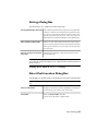
Check In Dialog Box . . . . . . . .
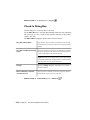
Settings Dialog Box . . . . . . . .
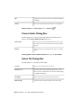
Select Vault Location Dialog Box .
Create Folder Dialog Box . . . . .
Select File Dialog Box . . . . . . .
Chapter 16
.
.
.
.
.
.
.
.
.
.
.
.
.
.
.
.
.
.
.
.
.
.
.
.
.
.
.
.
.
.
.
.
.
.
.
.
.
.
.
.
.
.
.
.
.
.
.
.
.
.
.
.
.
.
.
.
.
.
.
.
.
.
.
.
.
.
.
.
.
.
.
.
.
.
.
.
.
.
.
.
.
.
.
.
.
.
.
.
.
.
.
.
.
.
.
.
.
.
.
.
.
.
.
.
.
.
.
.
.
.
.
.
.
.
.
.
.
.
.
.
.
.
.
.
.
.
.
.
.
.
.
.
.
.
.
.
.
.
.
.
.
.
.
.
.
.
.
.
.
.
.
.
.
.
.
.
.
.
.
.
.
.
.
.
.
.
.
.
.
.
.
.
.
.
.
.
.
.
.
.
.
.
.
.
.
.
.
.
.
. 679
. 681
. 683
. 683
. 685
. 685
. 686
. 686
. 687
. 687
. 688
Edit Key Frame Dialog Box . . . . . . .
Edit Link Dialog Box . . . . . . . . . .
Edit Viewpoint Dialog Box . . . . . . .
Export Rendered Image Dialog Box . .
File Options Dialog Box . . . . . . . .
Culling Tab . . . . . . . . . . . .
Orientation Tab . . . . . . . . .
Speed Tab . . . . . . . . . . . . .
Headlight Tab . . . . . . . . . .
Scene Lights Tab . . . . . . . . .
DataTools Tab . . . . . . . . . .
Units and Transform Dialog Box . . .
Image Export Dialog Box . . . . . . .
InfoCenter Settings Dialog Box . . . .
General Node . . . . . . . . . .
Communication Center Node . .
Autodesk Channels Page . .
Balloon Notification Page .
RSS Feeds Page . . . . . . .
New Link Dialog Box . . . . . . . . .
Options Editor Dialog Box . . . . . . .
General Node . . . . . . . . . .
Undo Page . . . . . . . . .
Locations Page . . . . . . .
Auto-Save Page . . . . . . .
Interface Node . . . . . . . . . .
Display Units Page . . . . .
Selection Page . . . . . . .
Measure Page . . . . . . . .
Snapping Page . . . . . . .
Viewpoint Defaults Page . .
Links Page . . . . . . . . .
Quick Properties Page . . .
Developer Page . . . . . . .
Display Page . . . . . . . .
3Dconnexion Page . . . . .
Navigation Bar Page . . . .
ViewCube Page . . . . . . .
SteeringWheels . . . . . . .
User Interface Page . . . . .
Model Node . . . . . . . . . . .
Performance Page . . . . .
NWD Page . . . . . . . . .
NWC Page . . . . . . . . .
File Exporters Node . . . . . . .
DWG Page . . . . . . . . .
.
.
.
.
.
.
.
.
.
.
.
.
.
.
.
.
.
.
.
.
.
.
.
.
.
.
.
.
.
.
.
.
.
.
.
.
.
.
.
.
.
.
.
.
.
.
.
.
.
.
.
.
.
.
.
.
.
.
.
.
.
.
.
.
.
.
.
.
.
.
.
.
.
.
.
.
.
.
.
.
.
.
.
.
.
.
.
.
.
.
.
.
.
.
.
.
.
.
.
.
.
.
.
.
.
.
.
.
.
.
.
.
.
.
.
.
.
.
.
.
.
.
.
.
.
.
.
.
.
.
.
.
.
.
.
.
.
.
.
.
.
.
.
.
.
.
.
.
.
.
.
.
.
.
.
.
.
.
.
.
.
.
.
.
.
.
.
.
.
.
.
.
.
.
.
.
.
.
.
.
.
.
.
.
.
.
.
.
.
.
.
.
.
.
.
.
.
.
.
.
.
.
.
.
.
.
.
.
.
.
.
.
.
.
.
.
.
.
.
.
.
.
.
.
.
.
.
.
.
.
.
.
.
.
.
.
.
.
.
.
.
.
.
.
.
.
.
.
.
.
.
.
.
.
.
.
.
.
.
.
.
.
.
.
.
.
.
.
.
.
.
.
.
.
.
.
.
.
.
.
.
.
.
.
.
.
.
.
.
.
.
.
.
.
.
.
.
.
.
.
.
.
.
.
.
.
.
.
.
.
.
.
.
.
.
.
.
.
.
.
.
.
.
.
.
.
.
.
.
.
.
.
.
.
.
.
.
.
.
.
.
.
.
.
.
.
.
.
.
.
.
.
.
.
.
.
.
.
.
.
.
.
.
.
.
.
.
.
.
.
.
.
.
.
.
.
.
.
.
.
.
.
.
.
.
.
.
.
.
.
.
.
.
.
.
.
.
.
.
.
.
.
.
.
.
.
.
.
.
.
.
.
.
.
.
.
.
.
.
.
.
.
.
.
.
.
.
.
.
.
.
.
.
.
.
.
.
.
.
.
.
.
.
.
.
.
.
.
.
.
.
.
.
.
.
.
.
.
.
.
.
.
.
.
.
.
.
.
.
.
.
.
.
.
.
.
.
.
.
.
.
.
.
.
.
.
.
.
.
.
.
.
.
.
.
.
.
.
.
.
.
.
.
.
.
.
.
.
.
.
.
.
.
.
.
.
.
.
.
.
.
.
.
.
.
.
.
.
.
.
.
.
.
.
.
.
.
.
.
.
.
.
.
.
.
.
.
.
.
.
.
.
.
.
.
.
.
.
.
.
.
.
.
.
.
.
.
.
.
.
.
.
.
.
.
.
.
.
.
.
.
.
.
.
.
.
.
.
.
.
.
.
.
.
.
.
.
.
.
.
.
.
.
.
.
.
.
.
.
.
.
.
.
.
.
.
.
.
.
.
.
.
.
.
.
.
.
.
.
.
.
.
.
.
.
.
.
.
.
.
.
.
.
.
.
.
.
.
.
.
.
.
.
.
.
.
.
.
.
.
.
.
.
.
.
.
.
.
.
.
.
.
.
.
.
.
.
.
.
.
.
.
.
.
.
.
.
.
.
.
.
.
.
.
.
.
.
.
.
.
.
.
.
.
.
.
.
.
.
.
.
.
.
.
.
.
.
.
.
.
.
.
.
.
.
.
.
.
.
.
.
.
.
.
.
.
. 690
. 692
. 692
. 694
. 696
. 696
. 698
. 698
. 699
. 699
. 699
. 700
. 701
. 702
. 703
. 703
. 703
. 704
. 704
. 705
. 706
. 706
. 707
. 707
. 707
. 708
. 709
. 709
. 710
. 711
. 711
. 712
. 714
. 715
. 715
. 720
. 720
. 721
. 723
. 725
. 725
. 726
. 728
. 728
. 729
. 730
Contents | xv
Revit Page . . . . . . . . . . .
DGN Page . . . . . . . . . . .
Viz/Max Page . . . . . . . . . .
Publish Dialog Box . . . . . . . . . . . . .
Piranesi EPix Dialog Box . . . . . . . . . .
QTVR Object Movie Settings Dialog Box .
Section Plane Settings Dialog Box . . . . .
Chapter 17
.
.
.
.
.
.
.
.
.
.
.
.
.
.
.
.
.
.
.
.
.
.
.
.
.
.
.
.
.
.
.
.
.
.
.
.
.
.
.
.
.
.
.
.
.
.
.
.
.
.
.
.
.
.
.
.
.
.
.
.
.
.
.
.
.
.
.
.
.
.
.
.
.
.
.
.
.
.
.
.
.
.
.
.
.
.
.
.
.
.
.
.
.
.
.
.
.
.
. 733
. 735
. 737
. 738
. 740
. 741
. 741
Glossary . . . . . . . . . . . . . . . . . . . . . . . . . . . . . 743
Index . . . . . . . . . . . . . . . . . . . . . . . . . . . . . . . 749
xvi | Contents
Welcome to Autodesk
Navisworks Simulate
2012
1
Autodesk Navisworks Simulate 2012 software provides advanced tools for and
powerful features to help you better communicate project information.
Multidisciplinary design data created in Building Information Modeling (BIM), digital
prototype, and process plant design applications can be combined into a single,
integrated project model. Comprehensive 4D scheduling, animation, and
photorealism capabilities enable users to demonstrate design intent and simulate
construction, helping to drive insight and predictability. Real-time navigation
combines with a review toolset to support collaboration among the project team.
Entire project models can be published and viewed in NWD and DWF™ file formats
to provide valuable digital assets during and after construction.
What Is New in This Release?
Autodesk Navisworks Simulate 2012 contains many new features and
enhancements.
Installation
The installation screen provides links to the installation options, deployment
options, installation tools and utilities. You also have the option of selecting
the DWG file readers that require installation, plus the exporter plugins that
you require and the Autodesk Navisworks Freedom viewer.
1
User Interface
Easy access to commonly used review and navigation tools to increase review
productivity.
■
The Viewpoint tab now includes the Navigate pane, providing access
to tools such as walk, pan, zoom, and orbit; SteeringWheels tracking
menus, 3Dconnexion 3D mouse, and the realism settings.
■
The gizmos have been updated, making it easier to manipulate objects and
section planes.
■
Section planes have also been enhanced to provide greater visual feedback
of their position and orientation.
2 | Chapter 1 Welcome to Autodesk Navisworks Simulate 2012
■
Selection sets can now be created faster with the addition of the Save
Selection
option (Home tab ➤ Select & Search panel).
Appearance Profiler
The Appearance Profiler allows you to set up custom appearance profiles
based on sets (search and selection) and property values, and use them to
color-code objects in the model to differentiate system types and visually
identify their status. Appearance profiles can be saved and used on other
projects, or shared between other Autodesk Navisworks users.
See Appearance Profiler (page 435).
What Is New in This Release? | 3
TimeLiner
The TimeLiner tool has been enhanced to provide you with greater control
and flexibility when working with 4D simulations. A new interface and
integrated, editable Gantt chart allow you to create, edit and communicate
your construction schedule more effectively. The new TimeLiner API allows
you to extend and tailor the 4D toolset to meet your project and business
requirements.
4 | Chapter 1 Welcome to Autodesk Navisworks Simulate 2012
■
The Tasks, Gantt View and Rules tab are now consolidated into a single
Tasks tab.
■
A column chooser allows you to select your preferred grid layout from
three default options or by choosing your own columns.
■
The interactive Gantt Chart lets you manipulate dates in the schedule
by dragging and positioning tasks, start and end dates.
■
A Gantt View is now available during 4D simulations on the Simulate
tab.
■
An ability to quickly add and edit tasks in a project schedule.
■
An ability to filter tasks by their status.
■
An ability to import / export TimeLiner rules for re-use.
■
New TimeLiner .NET API. Using the API you can now obtain a list of
tasks, task types, simulation types and data sources; add, edit and delete
tasks, task types, simulation types and data sources and modify their
properties; subscribe to events that will be triggered when the GUI or other
API users make changes to tasks, task types, simulation types and data
sources.
See Overview of the TimeLiner Tool (page 603).
Autodesk File Format Support
Autodesk Navisworks now offers 2D DWF and multi-sheet DWF support,
allowing you to open, review and explore your 2D datasets alongside your 3D
models. Importantly, the 2D view is integrated with the 3D environment -
What Is New in This Release? | 5
this enables you to select a component in the 3D model and then to find and
review the same component in a 2D representation (such as a floor plan or
section) providing you with the most appropriate view of the data for the task
that you are undertaking. When working with the FBX visualization file format
you can now achieve an accurate transfer of materials, textures and lights
when importing or exporting data between Autodesk Navisworks and other
FBX compatible applications.
■
Support for opening 2D/3D DWF and DWFx files. See DWF File Reader
(page 178).
■
Support for exporting 3D DWF and DWFx files. See Export 3D DWF/DWFx
Files (page 487).
■
Multi-sheet file support. See 2D and Multi-Sheet Files (page 212).
■
2D/3D Object Association support. See Find All Sheets and Models Containing the Selected Object (page 356).
■
FBX consistent material support for lights, materials, and textures. See FBX
File Reader.
Extended Support for Revit
A number of interoperability improvements to Revit / Autodesk Navisworks
workflows increases your productivity when working with both applications.
■
Revit SwitchBack allows you to quickly transition between views in
Autodesk Navisworks and Revit for easy navigation and location of
elements. See Revit SwitchBack (page 434).
■
Support for Revit Construction modelling enables you to pass your
construction parts into Autodesk Navisworks for 4D simulation.
■
Support for Revit linked files.
■
Support for Revit split regions.
■
Support for Revit properties including areas, volumes and points.
6 | Chapter 1 Welcome to Autodesk Navisworks Simulate 2012
See Revit File Exporter (page 199).
Vault Integration
Autodesk Navisworks now offers integration with the Autodesk Vault data
management toolset. Autodesk Vault offers a comprehensive environment
for managing the large volume of data that is generated on your projects.
■
Retrieve/save data.
■
Check in/check-out data.
■
Manage file versioning and the relationship between NWF files and design
data.
See Use the Autodesk Vault Add-In (page 665).
General Integration Enhancements
■
Support for Google Sketchup v7 .skp files with backwards compatibility.
■
TimeLiner now offers support for Primavera P6 v7 web services.
■
Support for Pro/Engineer .prt, .asm, .g and .neu file formats.
What Is New in This Release? | 7
■
Point cloud server support. Autodesk Navisworks now supports the retrieval
of data from external point cloud engines for display within your Autodesk
Navisworks model. The tool is implemented as an extension to the existing
NWCreate API. A simple generic example and a customized example
demonstrating connection to Z+F LFM server are available within the
NWCreate API resources.
Autodesk Navisworks Freedom 2012 Enhancements
■
The Review tab now contains Measure tools supporting field access to
dimensioning and area calculation.
■
You can now open 2D DWF, and multi-sheet DWF files, as well as NWD
files.
■
A Gantt View is now available during 4D TimeLiner simulations.
8 | Chapter 1 Welcome to Autodesk Navisworks Simulate 2012
Miscellaneous Enhancements
■
Enhanced support for the
■
3D mouse through an extended interface. See 3Dconnexion 3D Mouse
(page 298).
■
Communication Centre now supports live updates.
■
New avatars to be used in a variety of roles ranging from construction
workers and safety professionals, to office workers. Since avatars can vary
per viewpoint, you can easily show how project stakeholders will interact
with a specific phase of the project in the relevant context.
■
Ongoing implementation of Autodesk Navisworks .NET API.
What Is New in This Release? | 9
How to Get Assistance
There are various ways to find information about how to use this program,
and multiple resources are available.
Find Information Using InfoCenter
You can use InfoCenter to search Autodesk Navisworks help file for
information. You can also easily access product updates and announcements.
Overview of InfoCenter
You can use InfoCenter to search for product-related help, display the
Subscription Center panel for subscription services, display the Communication
Center panel for product updates and announcements, and display the
Favorites panel to access saved topics.
You can use InfoCenter to:
■ Search for information in the main product Help through keywords (or
by entering a phrase)
■
Access subscription services through Subscription Center panel
■
Access to product-related updates and announcements through
Communication Center panel
■
Access saved topics through Favorites panel
To display the InfoCenter box in a collapsed state, click the arrow to its left.
10 | Chapter 1 Welcome to Autodesk Navisworks Simulate 2012
To rearrange the topics displayed on a panel
1 Display a panel by doing one of the following:
■ In the InfoCenter box, click the Subscription Center button.
■
In the InfoCenter box, click the Communication Center button.
■
In the InfoCenter box, click the Favorites button.
2 Click and drag a category or group header to the desired position.
TIP To keep the Subscription Center, Communication Center, and the
Favorites panel expanded, click the push pin icon in the bottom-right corner
of the panel.
NOTE You can rearrange categories within a group, but you cannot move them
into other groups.
Search for Information
You can enter keywords or a phrase in the InfoCenter box to search for
information.
When you enter keywords or a phrase in the InfoCenter box, you search the
contents of the main Autodesk Navisworks Help file.
Keyword searches produce better results. The results are listed on the Help
Search tab. Click a topic to display it in help.
When you use InfoCenter to search for information, you can use the following
special symbols in your query to refine or expand it. These symbols can be
used alone or can be combined.
Symbol
Description
*
Replaces one or more characters when used at the beginning,
middle, or end of a word. For example, “*lish”, “p*lish”, and “pub*”
will find “publish”. Also, “anno*” will find “annotative”, “annotation”, “annoupdate”, “annoreset”, and so on.
How to Get Assistance | 11
Symbol
Description
?
Replaces a single character. For example, “cop?” will find “copy”,
but not “copybase”.
~
Adds grammatical form variations to a keyword when added at the
beginning or end of a word. For example, “plotting~” will find
“plots”, “plotted”, and so on. Also, “~plot” will find “preplot”,
“replot”, and so on.
When performing the exact phrase search, use double quotation marks (" ")
to enclose words that must appear next to each other in the specified text
string. For example, enter "specify units of measurement" to find only
topics with all those words in that order. You can also use the previously
mentioned symbols in a text string that is enclosed in double quotation marks.
To search the main Help file for information
1 In the InfoCenter box, enter a keyword or phrase.
2 Click the Search button.
The main Help file opens, and the search results are listed on the Help Search
tab.
Access Subscription Center
Subscription Center displays links to information about subscription services
such as product enhancements, personalized web support from Autodesk
technical experts, and self-paced e-Learning.
If you are a subscription member, you can access subscription services by
clicking the Communication Center
button in the InfoCenter box,
and then clicking a Subscription Center link. To learn more about Autodesk
subscription membership, visit http://www.autodesk.com/subscriptioncenter.
About Subscription Center
With Autodesk Subscription, you get the latest releases of Autodesk software,
incremental product enhancements, personalized web support from Autodesk
12 | Chapter 1 Welcome to Autodesk Navisworks Simulate 2012
technical experts, and self paced e-Learning. Subscription services are available
to subscription members only.
By clicking the Communication Center
button in the InfoCenter box,
members have access to the following options (under Subscription Center):
■ Subscription status. Checks your subscription status.
■
Create support request. Provides direct one-to-one communication
with Autodesk support technicians. You receive fast, complete answers to
your installation, configuration, and troubleshooting questions.
■
View support requests. Tracks and manages your questions and
responses through Autodesk's state-of-the-art support system.
■
Edit Subscription Center profile. Sets up and maintains your
subscription account.
■
View e-Learning catalog. Features interactive lessons organized into
product catalogs.
■
e-Learning Lessons. (For subscription members only.) Each lesson is
15-30 minutes and features hands-on exercises, with an option to use a
simulation instead of the software application. You can use an online
evaluation tool that identifies gaps in skills, determines what lessons will
be most helpful, and gauges learning progress.
Subscription Resources and Privacy
Subscription resources provide interactive product features over the Internet.
Each time you access subscription resources (such as e-Learning or Create
Support Request) from Communication Center in an Autodesk product,
product information (such as the serial number, version, language, and the
subscription contract ID) is sent to Autodesk for verification that your product
is on subscription.
Autodesk compiles statistics using the information sent to subscription
resources to monitor how they are being used and how they can be improved.
Autodesk maintains the information provided by or collected from you in
accordance with Autodesk's published privacy policy, which is available at
http://www.autodesk.com/privacy.
To open the Subscription Center
1 Click the Communication Center
button in the InfoCenter box.
2 On the Communication Center panel, under Subscription Center,
click the subscription resource you want to access.
How to Get Assistance | 13
NOTE Subscription Center is not available to all product users. If subscription
resources are not available in your product, your product is not entitled to
subscription benefits.
Manage Files with Autodesk Vault
If you are a subscription customer, you have access to Autodesk Vault, a file
management tool that provides a repository where documents and files are
stored and managed.
Autodesk Vault gives you more power to manage files and track changes.
Versioned copies of master files are maintained, allowing you to easily revert
to earlier versions of files. You can check files out for editing and later check
them back in. The master copy is never directly edited.
Autodesk Vault consists of two required components: the Autodesk Data
Management Server and the Vault Client. Optionally, you can also install the
Vault Office Add-in.
For information about using the Vault, refer to the Vault Help system.
TIP The main components for the Autodesk Vault can be downloaded from the
Autodesk Subscription site.
Use Communication Center
Communication Center provides up-to-date product information, software
updates, product support announcements, and other product-related
announcements.
Overview of Communication Center
You can click the Communication Center button to display links to
information about product updates and announcements, and may include
links to RSS feeds.
Whenever new information is available, Communication Center notifies
you by displaying a balloon message below the Communication Center
button in the InfoCenter box.
14 | Chapter 1 Welcome to Autodesk Navisworks Simulate 2012
Communication Center provides the following types of announcements:
■ Autodesk Channels: Receive support information, product updates, and
other announcements (including articles and tips).
■
RSS Feeds. Receive information from RSS feeds to which you subscribe.
RSS feeds generally notify you when new content is posted. You are
automatically subscribed to several default RSS feeds when you install the
program.
■
Product Support Information. Get breaking news from the Product
Support team at Autodesk, including when Live Update maintenance
patches are released.
■
Subscription Announcements. Receive subscription announcements
and subscription program news, as well as links to e-Learning Lessons, if
you are an Autodesk subscription member (available in countries/regions
where Autodesk subscriptions are offered).
For more information about Autodesk Subscription, see Access Subscription
Center (page 12).
■
Articles and Tips. Be notified when new articles and tips are available
on Autodesk websites.
■
Live Update Maintenance Patches. Receive automatic notifications
whenever new maintenance patches are released from Autodesk.
■
Featured Technologies and Content. Learn more about third-party
developer applications and content.
You can customize the items that display on the Communication Center
panel. For more information, see Specify InfoCenter Settings (page 22).
Communication Center Online Policy
Communication Center is an interactive feature that must be connected to
the Internet in order to deliver content and information. Each time
Communication Center is connected, it sends your information to Autodesk
so that you receive the correct information. All information is sent
anonymously to Autodesk to maintain your privacy.
Communication Center sends the following information to Autodesk:
■ Product name (in which you are using Communication Center)
■
Product release number
■
Product language
■
Country/region (specified in the Communication Center settings)
How to Get Assistance | 15
■
Your unique Customer Involvement Program (CIP) ID if you are
participating in the CIP program
Autodesk compiles statistics using the information sent from
Communication Center to monitor how it is being used and how it can
be improved. Autodesk maintains information provided by or collected from
you in accordance with the company's published privacy policy, which is
available at http://www.autodesk.com/privacy.
To open Communication Center
■
In the InfoCenter box, click the Communication Center
button.
To receive new information notifications
■
Click the link in the balloon message to open the article or announcement.
Save and Access Favorite Topics
You can click the Favorites button to display saved links to topics or web
locations.
Any link that displays on the Subscription Center or Communication
Center panel can be marked as a favorite.
A link marked as a favorite displays a star icon on the Subscription Center
panel or the Communication Center panel.
To display the InfoCenter Favorites panel
■
In the InfoCenter box, click the Favorites button.
NOTE The links displayed on the Favorites panel are organized into the same
groups or categories from which they were added.
To save a link in InfoCenter as a favorite
1 Display a panel by doing one of the following:
■ In the InfoCenter box, click the Subscription Center button.
16 | Chapter 1 Welcome to Autodesk Navisworks Simulate 2012
■
In the InfoCenter box, click the Communication Center button.
2 Click the star icon that is displayed next to the link that you want to
save as a favorite.
To remove a favorite link from the InfoCenter Favorites panel
1 In the InfoCenter box, click the Favorites button to display the Favorites
panel.
2 Click the star icon that is displayed next to the link that you want to
remove from the Favorites panel.
Use the Help System
You can click the Help button to display topics in Help.
You can get much more benefit from the Help system when you learn how
to use it efficiently. You can quickly find general descriptions, procedures,
details about dialog boxes and palettes, or definitions of terms.
The Help system contains complete information about using this program.
In the Help window, you use the left pane to locate information. The tabs
above the left pane give you several ways for finding the topics you want to
view. The right pane displays the topics you select.
To display topics in Help
■
In the InfoCenter box, click the Help button.
How Help Topics Are Organized
Most topics in this Help system have three tabs above the right pane of the
Help window. The tabs display different types of information.
■
Concept tab. Describes a feature or function. When you click the
Concept tab, the Help Contents list in the left pane of the Help window
expands and highlights the current topic. The Contents tab displays the
How to Get Assistance | 17
structure of the Help on that topic. You can easily display nearby topics
by clicking them in the list.
■
Procedure tab. Provides step-by-step instructions for common procedures
related to the current topic. After displaying a procedure, you can click the
Procedure tab to redisplay the current list of procedures.
■
Quick Reference tab. Lists reference information related to the current
topic.
When you click a different tab, the topic remains the same. Only the type of
information displayed—concept, procedures, or quick reference links—is
different.
Search in Help
Use the Help Search tab to find relevant topics based on keywords that you
enter.
The basic search rules are as follows:
■ Type your keywords in uppercase or lowercase characters; searches are not
case-sensitive.
■
Search for any combination of letters (a-z) and numbers (0-9).
■
Do not use punctuation marks such as a period, colon, semicolon, comma,
hyphen, and single quotation marks; they are ignored during a search.
■
Group the elements of your search using double quotation marks or
parentheses to set each element apart.
Use Wild Card Characters
You can use the following wild card characters in any keyword:
Symbol
Description
*
Replaces one or more characters when used
at the beginning, middle, or end of a word.
For example, “*lish”, “p*lish”, and “pub*”
will all find “publish”. Also, “anno*” will
find “annotative”, “annotation”, “annoupdate”, “annoreset”, and so on.
18 | Chapter 1 Welcome to Autodesk Navisworks Simulate 2012
Symbol
Description
?
Replaces a single character. For example,
“cop?” will find “copy”, but not “copybase”.
~
Expands the tense of the word at the beginning or end of a word. For example, “plotting~” will find “plots”, “plotted”, and so
on. Also, “~plot” will find “preplot”,
“replot”, and so on.
Search for Phrases
When searching for a phrase, use double quotation marks (“ ”) to enclose
words that must appear next to each other in the specified sequence. For
example, enter “specifying units of measurement” to find only topics with all
those words in that order. If you don’t use the quotation marks around that
text, Help finds all topics containing any one of the listed words, that is, all
topics containing “specifying”, all topics containing “units”, all topics
containing “of”, and all topics containing “measurement”.
TIP If you can’t find the information you need through a search, try using the
Contents tab.
Use Boolean Operators
With the AND, OR, NOT, and NEAR operators, you can precisely define your
search by creating a relationship between search terms. The following table
shows how you can use each of these operators. If no operator is specified,
AND is used. For example, the query spacing border printing is equivalent to
spacing AND border AND printing.
Search for
Example
Results
Both terms in the same
topic
“tree view” AND “palette”
Topics containing both the words
“tree view” and “palette”
Either term in a topic
viewpoint OR animation
Topics containing either the word
“viewpoint” or the word “animation” or both
How to Get Assistance | 19
Search for
Example
Results
The first term without
the second term
nwd NOT nwc
Topics containing the word
“NWD”, but not the word
“NWC”
Both terms in the same
topic, close together
user NEAR menu
Topics containing the word
“user” within eight words of the
word “menu”
NOTE The |, &, and ! characters do not work as Boolean operators. You must use
AND (also +), OR, and NOT (also -).
Find Information in Help Topics
The tabs on the left side of the Help window provide different methods for
finding information.
Contents Tab
■
Presents an overview of the available documentation in a list of topics and
subtopics.
■
Allows you to browse by selecting and expanding topics.
■
Provides a structure so you can always see where you are in Help and
quickly jump to other topics.
Index Tab
■
Displays an alphabetical list of keywords related to the topics listed on the
Contents tab.
■
Accesses information quickly when you already know the name of a feature,
command, or operation, or when you know what action you want the
program to perform.
Search Tab
■
Provides a keyword search of all the topics listed on the Contents tab.
■
Accepts the Boolean operators AND (+), OR, NOT (-), and NEAR.
20 | Chapter 1 Welcome to Autodesk Navisworks Simulate 2012
■
Accepts the wild cards *, ?, and ~.
■
Allows you to perform a search for a phrase when the phrase is enclosed
in double quotes.
■
Displays a ranked list of topics that contain the word or words entered in
the keyword field.
■
Arranges the results alphabetically by title or by location if you click on
the Title and Location column headings.
To find a specific word or phrase in the currently displayed Help topic
1 Click in the topic text and press CTRL+F.
2 In the Find text box, enter a keyword or phrase.
3 Click Next. If the keyword or phrase is located, the topic scrolls to display
the result.
Print Help Topics
The quickest way to print the current topic is to right-click within the topic
and click Print.
The Print button on the Help toolbar provides these print options:
■ Print the selected topic (recommended)
■
Print the selected heading and all subtopics
NOTE When you select the second option, you may get numerous printed pages,
depending on how many subtopics the currently selected topic contains.
To print a Help topic
1 Display the topic you want to print.
2 Right-click in the topic pane. Click Print.
3 In the Print dialog box, click Print.
To print a selected heading and all subtopics
1 Display the topic you want to print and make sure that the Contents
tab is displayed.
2 On the Help toolbar, click Print.
How to Get Assistance | 21
3 In the Print Topics dialog box, click Print the Selected Heading
and All Subtopics.
4 Click OK.
Show and Hide the Contents Pane
You can control the size of the Help window.
Use the Hide
button on the Help toolbar to shrink the Help window
to a compact size by hiding the pane that contains the Contents, Index,
and Search tabs. The compact window size is best for displaying procedures
while you work.
Use the Show
button to expand the Help window to display the pane
that contains Contents, Index, and Search tabs. The expanded window
size is best for locating and displaying conceptual and reference information.
Specify InfoCenter Settings
You can specify general and Communication Center settings in the
InfoCenter Settings dialog box.
In the InfoCenter Settings dialog box, you can specify the following settings:
■ General. Your current location, frequency for checking new online content
and option to turn on or off animated transition effects for the InfoCenter
panels.
■
Communication Center. Set the maximum age of the articles displayed
on the Communication Center panel.
■
Autodesk Channels. Channels to display in the Communication Center
panel as well as the number of articles to display for each channel.
■
Balloon Notification. Notifications for new product information,
software updates, and product support announcements. Also, you can
customize the transparency and the display time of the balloon.
■
RSS Feeds. RSS feed subscriptions. You can add or remove RSS feeds. RSS
feeds generally notify you when new content is posted.
22 | Chapter 1 Welcome to Autodesk Navisworks Simulate 2012
To specify the channels to display in the Communication Center panel
1 Display a panel by doing one of the following:
■ In the InfoCenter box, click the Subscription Center button.
■
In the InfoCenter box, click the Communication Center button.
■
In the InfoCenter box, click the Favorites button.
2 Click the InfoCenter Settings
button.
3 In the InfoCenter Settings dialog box, in the left pane, click Autodesk
Channels.
4 In the right pane, select or clear the channels you want to display in the
Communication Center panel.
5 Click OK.
To specify InfoCenter balloon notification settings
1 Display a panel by doing one of the following:
■ In the InfoCenter box, click the Subscription Center button.
■
In the InfoCenter box, click the Communication Center button.
■
In the InfoCenter box, click the Favorites button.
2 Click the InfoCenter Settings
button.
3 In the InfoCenter Settings dialog box, in the left pane, click Balloon
Notification.
4 In the right pane, select or clear the options to turn balloon notification
on or off.
5 Enter the number of seconds to set the length of time for balloon
notifications to display.
6 Enter the transparency value of the balloon or set the value using the
slider.
7 Click OK.
To add an RSS feed to Communication Center
1 Display a panel by doing one of the following:
■ In the InfoCenter box, click the Subscription Center button.
■
In the InfoCenter box, click the Communication Center button.
2 Click the InfoCenter Settings button
.
3 In the InfoCenter Settings dialog box, in the left pane, click RSS Feeds.
How to Get Assistance | 23
4 In the right pane, do one of the following:
■ Click Add.
■
Right-click anywhere in the right pane. Click Add.
5 In the Add RSS Feed dialog box, enter the location of the RSS feed you
want to add. Click Add.
6 In the InfoCenter - RSS Feed Confirmation dialog box, click Close.
7 Click OK.
To remove an RSS feed from Communication Center
1 Display a panel by doing one of the following:
■ In the InfoCenter box, click the Subscription Center button.
■
In the InfoCenter box, click the Communication Center button.
■
In the InfoCenter box, click the Favorites button.
2 Click the InfoCenter Settings
button.
3 In the InfoCenter Settings dialog box, in the left pane, click RSS Feeds.
4 In the right pane, do one of the following:
■ Click Remove.
■
Right-click an RSS feed. Click Remove.
5 In the InfoCenter - Remove RSS Feed dialog box, click Yes.
6 Click OK.
Get More Help
You can access several additional sources of help.
■
Use Communication Center. Display the Communication Center
panel for product updates and announcements.
■
Press F1. Displays context-sensitive reference information.
■
Click the Help button in many dialog boxes. Displays reference
information for the dialog box.
■
View the product Readme. Displays late-breaking information about
this product.
24 | Chapter 1 Welcome to Autodesk Navisworks Simulate 2012
Other resources help you get information about Autodesk products and
assistance with your questions about this program.
■ Autodesk website. Access http://www.autodesk.com.
■
Local support. Check with your dealer or Autodesk country/region office.
Learn the Product
Training programs and products from Autodesk help you learn the key
technical features and improve your productivity.
For the latest information about Autodesk training, visit http://www.autodesk.com/training or contact your local Autodesk office.
Autodesk Authorized Training Centers
The Autodesk® Authorized Training Center (ATC®) network delivers
Autodesk-authorized, instructor-led training to design professionals who use
Autodesk software. Autodesk Authorized Training Centers use experienced
and knowledgeable instructors. More than 1,200 ATC sites are available
worldwide to meet your needs for discipline-specific, locally based training.
To find a training center near you, contact your local Autodesk office or visit
http://www.autodesk.com/atc.
Autodesk Official Training Courseware
Autodesk Official Training Courseware (AOTC) is technical training material
developed by Autodesk. Designed for traditional 1/2-day to 5-day, instructor-led
classroom training and used by Authorized Training Centers and other
Autodesk partners, AOTC is well-suited for self-paced, stand-alone learning.
The manuals cover key concepts and software functionality with hands-on,
step-by-step, real-world exercises. You can purchase AOTC from your local
reseller or distributor, or you can order it online from the Autodesk Store at
http://www.autodesk.com/aotc.
e-Learning
Autodesk e-Learning for Autodesk Subscription customers features interactive
lessons organized into product catalogs. Each lesson is 20-40 minutes in length
and features hands-on exercises, with an option to use a simulation of the
product or the actual application. You can also use an online evaluation tool
How to Get Assistance | 25
that identifies gaps in skills, determines what lessons will be most helpful,
and gauges learning progress.
If you are a member of Autodesk subscription, you can access e-Learning and
other subscription services from within your Autodesk product.
For more information about how to access e-Learning in the product, see Access
Subscription Center (page 12).
For more information about Autodesk subscription resources, visit http://www.autodesk.com/subscriptioncenter.
Autodesk Developer Network
The Autodesk Developer (ADN) program for ADN members provides support
for full-time, professional developers who want to build software based on
Autodesk products. As an ADN member, you will receive the business, software,
support, and training you need to be successful. If you are a developer, visit
http://www.autodesk.com/adn.
Autodesk Consulting
Autodesk Consulting provides services that help set up processes and provide
critical training that will help increase productivity so you can capitalize on
the power of your products. For more information on general consulting,
systems integration, or custom training services, visit http://www.autodesk.com/consulting.
Partner Products and Services
Autodesk works together with thousands of software partners around the
world. These partners provide products and services that enhance Autodesk
products for design professionals. Visit the Partner Products & Services page
at http://www.autodesk.com/partnerproducts for a list of resources available for
your Autodesk product and your industry.
View the Product Readme
You can find late-breaking information about this software in the Readme.
It is suggested that you read through the Autodesk Navisworks Readme for
information about recommended hardware, updated installation instructions,
and known software problems. The Readme file is available from the product’s
program group on the Windows Start menu.
26 | Chapter 1 Welcome to Autodesk Navisworks Simulate 2012
Join the Customer Involvement Program
You are invited to help guide the direction of Autodesk design software.
If you participate in the Customer Involvement Program (CIP), specific
information about how you use Autodesk Navisworks is forwarded to Autodesk.
This information includes what features you use the most, problems that you
encounter, and other information helpful to the future direction of the
product.
See the following links for more information.
■ Learn more about the Autodesk Customer Involvement Program: http://www.autodesk.com/cip
■
Read the Autodesk Privacy Statement: http://www.autodesk.com/cipprivacy
When you join, you will be able to view reports that can help you optimize
your use of Autodesk Navisworks.
To turn the CIP on or off
1 On the InfoCenter toolbar, to the right of the Help button, click the
drop-down arrow.
2 Click Customer Involvement Program.
3 In the Customer Involvement Program dialog box, select to start or stop
participating.
4 Click OK.
How to Get Assistance | 27
28
Installation
2
Quick Start to Stand-Alone Installation
This section provides step-by-step instructions about how to prepare, and then
install Autodesk Navisworks.
Stand-alone installation is recommended for individual users or small groups.
The key point is that you will repeat the installation process on each computer.
For a stand-alone license this is the only valid installation type, but it can also
be used with a multi-seat stand-alone or network license.
If you have never installed the product before, you should familiarize yourself
with the entire installation process and options before beginning.
For information about installing network-licensed or multi-seat stand-alone
versions of the program, see Install Autodesk Navisworks for Multiple Users
(page 44).
Prepare for Installation
To prepare for installation, you should review the system requirements,
understand administrative permission requirements, locate your Autodesk
Navisworks Simulate 2012 serial number and product key, and close all running
applications.
Complete these tasks, and you are ready to begin installing Autodesk Navisworks
Simulate 2012.
NOTE It is also recommended that you install Microsoft .Net Framework 4.0 before
installing the product. See Install Microsoft .Net Framework 4.0 (page 31).
29
System Requirements for Stand-Alone Installation
The first task you need to complete is to make sure that your computer meets
the minimum system requirements. If your system does not meet these
requirements, problems can occur, both within Autodesk Navisworks and at
the operating system level.
Whether your Windows operating system is the 32-bit or the 64-bit version,
the version is automatically detected during installation.
See the following table for hardware and software requirements.
Hardware and software requirements for client machine
Hardware/Software
Requirement
Operating System
Microsoft® Windows 7 (32-bit or 64-bit) Home Basic, Home Premium, Professional, Enterprise, or Ultimate (recommended)
Microsoft® Windows Vista® SP2 (32-bit or 64-bit)
Home Premium, Business, Enterprise, or Ultimate
Microsoft® Windows XP SP3 (32-bit) Home, or
Professional
Microsoft® Windows XP SP2 (64-bit) Professional
Web browser
Microsoft® Internet Explorer® 7.0 or later
Processor
AMD Athlon™, 3.0 GHz or faster (minimum); Intel®
Pentium® 4, 3.0 GHz or faster (recommended) with SSE2 technology
Memory (RAM)
512 MB (minimum); 2 GB or more (recommended)
VGA Display
1024 x 768 with true color (minimum)
1280 x 1024 32-bit color video display adapter with
true color (recommended)
30 | Chapter 2 Installation
Hardware and software requirements for client machine
Graphics Card
Direct3D 9® and OpenGL® capable graphics card
with Shader Model 2 (minimum)
Hard disk
11 GB free disk space for installation
Pointing device
Microsoft® Mouse-compliant pointing device
DVD-ROM
Any speed (for installation only)
Optional hardware
Printer or plotter
Modem or access to an Internet connection
Network interface card
Install Microsoft .Net Framework 4.0
Autodesk Navisworks Simulate 2012 requires Microsoft .Net 4.0 to be installed
prior to product installation.
Most Windows updates should include Microsoft .NET Framework 4, however,
for old versions of Windows, you can download and install Microsoft .NET
Framework 4 redistributables from: http://www.microsoft.com/downloads/en/details.aspx?FamilyID=0a391abd-25c1-4fc0-919f-b21f31ab88b7 or install Microsoft
.Net Framework 4 from the following directory in the installation media:
\3rdParty\NET\4\wcu\dotNetFramework\.
The Installation wizard will install Microsoft .Net Framework 4 if it detects
that required updates have not been installed.
Quick Start to Stand-Alone Installation | 31
NOTE If the Installation wizard prompts you to install the Microsoft .NET 4.0
Framework, the .NET 4.0 Framework installer may prompt you to first install the
Windows Imaging Component (WIC). This can occur if you do not have the latest
Microsoft Windows updates or service packs. You are most likely to need WIC if
you are running Windows XP SP2 without certain Windows Updates installed. If
required, the Microsoft WIC installers are available at the following locations:
■ 32-bit installer: http://www.microsoft.com/downloads/en/details.aspx?FamilyID=8e011506-6307-445b-b950-215def45ddd8&displaylang=en
■
64-bit installer: http://www.microsoft.com/downloads/en/details.aspx?FamilyID=f64654ac-6e26-41d9-a90a-0e7783b864ee
Understand Administrative Permission
Requirements
To install Autodesk Navisworks, you must have administrator permissions.
You do not need to have domain administrative permissions. See your system
administrator for information about administrative permissions.
To run Autodesk Navisworks, you do not need administrator permissions. You
can run the program as a limited user.
Locate Your Autodesk Navisworks Serial Number
and Product Key
When you install Autodesk Navisworks, you are prompted for your serial
number and product key in the User and Product Information page.
The serial number must contain a three-digit prefix followed by an eight-digit
number. The product key consists of five digits.
The serial number and product key are located on the outside of the product
packaging, or in the email you received if you downloaded your product. Make
sure to have these available before you install the program so that you don't
have to stop in the middle of the installation. Also make sure to have these
available before you activate the program.
The information you enter is permanently retained with the product. Because
you can’t change this information later without uninstalling, take care when
32 | Chapter 2 Installation
entering the information. To review this product information later, in the
InfoCenter box, click the down arrow next to the Help button ➤ About
Autodesk Navisworks Simulate 2012.
NOTE If you have lost your serial number or product key, contact your local
Autodesk office for assistance.
Avoid Data Loss During Installation
The Autodesk Navisworks installation process may stop if some applications
(such as Microsoft® Outlook® or virus-checking programs) are running.
Close all running applications to avoid possible data loss.
Choose a Language
You can select a different language for installation instructions, and a language
for individual product installations in the same install process.
When you start the installation process, the installer automatically determines
your operating system language. If a supported language is detected, your
install pages are displayed in that language. If you want to change that
language, you select a different one from the Installer Language list on the
first page of the Installation wizard.
NOTE Some products may not have multi-language support at the time of product
release. Additional language support may be available later. Check http://support.autodesk.com for the availability of additional language packs.
Using Language Packs
Language packs support use of different languages in each Autodesk Navisworks
product, including exporters. Pack names start with NAVFREE_, NAVSIM_,
NAVMAN_, and exporters_ respectively.
NOTE You must install at least one language pack for each product.
Quick Start to Stand-Alone Installation | 33
It is possible to install additional language packs to Autodesk Navisworks
products later. You can manually install the required language packs by
double-clicking on the language pack MSI file.
Language packs are located on the installation DVD and unpacked downloaded
media under the x86 folder for 32-bit products and under the x64 folder for
64-bit products.
■
Language packs for specific products are included in the NAVFREE,
NAVSIM, NAVMAN, and NWEXPORT subfolders of x86 and x64 folders.
■
Language packs for specific languages are included in the en-US (English),
de-DE (German), es-ES (Spanish), fr-FR (French), it-IT (Italian), ja-JP
(Japanese), ko-KR (Korean), pt-BR (Brazilian Portuguese), ru-RU (Russian)
and zh-CN (Chinese PRC) subfolders of the product folders.
So, for example, to install the 32-bit French language pack for Autodesk
Navisworks Simulate, double-click x86/NAVSIM/fr-FR/NAVSIM_LP.msi.
Configuration
During the installation process, you choose either a typical installation (install
the product with default settings), or a customized installation. On the Install
➤ Configure Installation page, for any product you have selected to install,
you will see a triangular control for access to a configuration panel.
Click anywhere in the product box to open the configuration panel:
■ Installation Type. If you choose a Typical installation (default settings)
the product installs the most common application features. A Custom
installation installs only the application features that you select from the
Select Features To Install list. The available features will depend upon
the product you are installing:
Redistributable ActiveX Control
34 | Chapter 2 Installation
Contains Autodesk Navisworks Redistributable ActiveX control.
API
Contains the Component Object Model
interface for customizing and extending
the Autodesk Navisworks functionality.
Example NWD files
Contains various feature sample files.
Batch Utility
Contains an add-in to run and schedule
commands.
Program
Contains full set of Autodesk Navisworks
files.
Sample RPCs
Contains several Rich Photorealistic Content
files.
NOTE For Autodesk Navisworks exporter plugins, you can change which
plugins are installed.
Indicates the third-party software already installed on your computer.
Indicates plugins for the third-party software, that are either not installed
or have not been detected by the Installation wizard.
Select the check boxes next to all required plugins. If the third-party
software has not been detected by the wizard, you can manually enable
the plugins for it. Selecting the check box automatically opens the dialog
box, which enables you to browse for the correct software installation
directory.
■
Create the Desktop Shortcut. Select the check box to create the desktop
shortcut for Autodesk Navisworks.
■
Project and Site Folders. Use the Browse buttons to select the
directories that will contain Autodesk Navisworks settings that can be
shared across an entire project site, or across a specific project group (see
Select the Project and Site Folders (page 64)).
■
Service Packs. If a service pack is available for your installation, you can
include it in the installation.
After you have configured the settings as required, click the product name to
close the configuration panel.
Quick Start to Stand-Alone Installation | 35
Install Multiple or Bundled Products
Some Autodesk packages are comprised of multiple products or are part of
multi-product bundles.
The Installation wizard for packages that are comprised of multiple products
gives you the option to choose which products you want to install.
In the Installation wizard, for packages containing multiple products, you can
choose which products and languages you want to install. During the install
process, you are informed whether a copy of the software is already installed.
You are also warned if your system does not meet the minimum system
requirements for the product. Each product name is displayed on its own
tabbed panel; you can configure them individually.
If you purchased a package that is a multi-product bundle, such as an
educational or institutional package, you may have a package that includes
several Autodesk products. For these bundled packages, an Installer disc
contains information for all the products in the package. The Installer disc
helps you install all of the products.
Install and Run Autodesk Navisworks
Simulate 2012
To use the product, you must install the product, register and activate it, and
then launch it.
You must have administrative permissions to install Autodesk Navisworks.
This section provides instructions for installing and activating Autodesk
Navisworks for an individual user on a stand-alone computer.
For information about installing network-licensed or multi-seat stand-alone
versions of the program, see Install Autodesk Navisworks for Multiple Users
(page 44).
When you have successfully installed Autodesk Navisworks Simulate 2012,
you are ready to register your product and start using the program. To register
the product, start Autodesk Navisworks Simulate 2012 and follow the on-screen
instructions. For more information, see How do I register and activate Autodesk
Navisworks? (page 75)
NOTE Autodesk does not recommend or support the distribution of an Autodesk
product using imaging software.
36 | Chapter 2 Installation
Install Autodesk Navisworks
The Autodesk NavisworksInstallation wizard contains all installation-related
material in one place.
From the Installation wizard, you can access user documentation, change
the installer language, select a language-specific product, install supplemental
tools, view support solutions, and learn about deploying your product on a
network.
NOTE The 32-bit and 64-bit versions of Autodesk Navisworks Simulate 2012 are
on separate DVDs. Insert the appropriate Autodesk Navisworks DVD in the DVD
drive to start the installation process. Follow the prompts to complete the
installation. As long as the DVD is in the drive, you can access user documentation
by clicking the Installation Help link.
■
Review installation documentation before you install. It is
recommended that you take the time to familiarize yourself with the
complete installation process before you install Autodesk Navisworks.
Documentation is accessible from links on the lower left corner of the
installer.
■
Install Autodesk Navisworks Simulate 2012. From the Installation
wizard, click Install. Follow the on-screen instructions to complete the
installation.
Install Autodesk Navisworks Using Default Values
This is the fastest means of installing Autodesk Navisworks on your system.
Only default values are used which means it is a typical installation being
installed to C:\Program Files\Autodesk\Navisworks Simulate 2012.
To install Autodesk Navisworks using default values on a stand-alone computer
1 Close all running applications on your computer and start the
Installation wizard.
Quick Start to Stand-Alone Installation | 37
2 On the Installation wizard, if required, select an alternate language
for the Installation wizard from the Installation Instructions
drop-down, and then click Install.
3 Review the Autodesk software license agreement for your country or
region. You must accept this agreement to proceed with the installation.
Choose your country or region, click I Accept, and then click Next.
NOTE If you do not agree to the terms of the license and want to terminate
the installation, click Cancel.
4 On the Product Information page, select Stand-Alone and enter
your serial number and product key, then click Next.
5 On the Configure Installation page, select the products to install,
and if required add a language pack(s) from the Product Language
drop-down (see Choose a Language (page 33)).
6 If required, use the Installation PathBrowse button to select the
drive and location where product will be installed.
7 Click Install. The wizard installs the products you selected using a
Typical installation, which installs the most common application
features. To see which features are included in a Typical installation,
refer to Typically Installed Features (page 72).
NOTE By default, the Installation wizard automatically enables the exporter
plugins for all third-party products already installed on your computer.
8 Click Finish.
Install Autodesk Navisworks Using Configured
Values
With this installation method, you can fine-tune exactly what gets installed.
You can alter the license type, the installation type, the install path, and
specify the location of the Project and Site folders.
To install Autodesk Navisworks using configured values on a stand-alone
computer
1 Close all running applications on your computer and start the
Installation wizard.
38 | Chapter 2 Installation
2 On the Installation wizard, if required, select an alternate language
for the Installation wizard from the Installation Instructions
drop-down, and then click Install.
3 Review the Autodesk software license agreement for your country or
region. You must accept this agreement to proceed with the installation.
Choose your country or region, click I Accept, and then click Next.
NOTE If you do not agree to the terms of the license and want to terminate
the installation, click Cancel.
4 On the Product Information page, select the License Type
(Stand-Alone or Network) and enter your serial number and product
key, then click Next.
5 On the Configure Installation page, select the products to install,
and if required add a language pack(s) from the Product Language
drop-down (see Choose a Language (page 33)).
6 Click the product name to open the configuration panel where you can
review and change settings. See Configuration (page 34). After you have
configured the settings as required, click the product name to close the
configuration panel.
7 If required, use the Installation PathBrowse button to select the
drive and location where product will be installed.
8 Click Install. The wizard installs the products you selected using your
Custom installation settings.
9 Click Finish.
Launch Autodesk Navisworks
Assuming that you’ve followed all of the previous steps outlined in this Quick
Start section, you can launch Autodesk Navisworks and start taking advantage
of its new and updated features.
You can start Autodesk Navisworks in the following ways:
■ Desktop shortcut icon. When you install Autodesk Navisworks, a
shortcut icon is placed on your desktop. Double-click the Autodesk
Navisworks icon to start the program.
■
Start button. Click Start ➤ All Programs ➤ Autodesk ➤ Navisworks
Simulate 2012 ➤ Autodesk Navisworks Simulate 2012.
■
Location where Autodesk Navisworks is installed. If you have
administrative permissions, you can run Autodesk Navisworks in the
Quick Start to Stand-Alone Installation | 39
location where you installed it. If you are a limited-rights user, you must
run Autodesk Navisworks from the Start button or from the desktop
shortcut icon. If you want to create a custom shortcut, make sure that the
Start In directory for the shortcut points to a directory where you have
write permissions.
NOTE When the product is started, by default, it uses the language that best
matches the settings on your computer. You can also launch Autodesk Navisworks
in another of the supported languages.
How to Launch Autodesk Navisworks in Another
Language
To run Autodesk Navisworks in another of the installed languages, you need
to add one of the language selector arguments to the desktop shortcut.
To run Autodesk Navisworks in another language
1 Right-click the Autodesk Navisworks desktop shortcut, and click
Properties on the shortcut menu to open the Autodesk
NavisworksProperties dialog box.
2 On the Shortcut tab, enter a space in the Target field after
..\roamer.exe, and then enter one of the following arguments:
■ -lang en-US for English localization
■
-lang de-DE for German localization
■
-lang es-ES for Spanish localization
■
-lang fr-FR for French localization
■
-lang it-IT for Italian localization
■
-lang ja-JP for Japanese localization
■
-lang ko-KR for Korean localization
■
-lang pt-BR for Brazilian Portuguese localization
■
-lang ru-RU for Russian localization
■
-lang zh-CN for Chinese (PRC) localization
3 Click OK to save the changes.
40 | Chapter 2 Installation
Add or Remove Features
You can add or remove Autodesk Navisworks Simulate 2012 features at any
time. For example, you may have chosen a Custom installation option when
you first installed Autodesk Navisworks, but now you want to add features
that you did not install originally. Or you may no longer need to use all of
the features that were installed originally.
You can add or remove features by using the Control Panel.
To add or remove features
1 Do one of the following:
■ (Windows XP) Click Start ➤ Settings ➤ Control Panel ➤ Add
or Remove Programs.
■
(Windows Vista and Windows 7) Click Start ➤ Control
Panel ➤ Programs and Features.
2 From the list of programs, click Autodesk Navisworks Simulate 2012,
and then click Change/Remove (Windows XP) or Uninstall/Change
(Windows Vista and Windows 7).
The Autodesk Navisworks Simulate 2012Installation wizard re-opens
in Maintenance Mode.
3 Click Add or Remove Features. On the Add/Remove Features
page, select a feature to install or uninstall. The icons to the left of the
selections give you an indication of the action that will be taken.
Indicates a feature that was marked for installation will be in a typical
installation.
Indicates a feature that is not currently scheduled for installation.
Indicates a feature that was not originally marked for installation,
but was added to the installed feature list.
Indicates an installed feature that is chosen for removal.
NOTE If you need to revert to the Autodesk Navisworks Simulate 2012
features that you selected in your original installation, click Cancel.
Click Update.
4 On the Update Complete page, you are informed when the updates
have been performed. Click Finish.
Quick Start to Stand-Alone Installation | 41
Repair Autodesk Navisworks Simulate 2012
If you accidentally delete or alter files that are required by Autodesk Navisworks
Simulate 2012, Autodesk Navisworks might not perform correctly, and you
might receive error messages when you try to execute a command or find a
file. You can attempt to fix this problem by repairing Autodesk Navisworks
Simulate 2012.
Repairing uses the features that were part of the installation type you chose
when you initially installed the program.
To repair Autodesk Navisworks Simulate 2012
1 Do one of the following:
■ (Windows XP) Click Start ➤ Settings ➤ Control Panel ➤ Add
or Remove Programs.
■
(Windows Vista and Windows 7) Click Start ➤ Control
Panel ➤ Programs and Features.
2 From the list of programs, click Autodesk Navisworks Simulate 2012,
and then click Change/Remove (Windows XP) or Uninstall/Change
(Windows Vista and Windows 7).
The Autodesk Navisworks Simulate 2012Installation wizard re-opens
in Maintenance Mode.
3 Click Repair or Reinstall.
4 On the Repair or Reinstall page, click RepairAutodesk Navisworks
Simulate 2012. This option replaces all registry entries that Autodesk
Navisworks initially installed and restores Autodesk Navisworks Simulate
2012 to its default state. Click Repair.
NOTE ReinstallAutodesk Navisworks Simulate 2012 repairs the registry
and reinstalls all files from the original installation. Use this option if the
RepairAutodesk Navisworks Simulate 2012 option does not solve the
problem.
5 On the Repair Complete page, click Finish.
Uninstall Autodesk Navisworks Simulate 2012
When you uninstall Autodesk Navisworks Simulate 2012, all components are
removed. This means that even if you've previously added or removed
42 | Chapter 2 Installation
components, or if you've reinstalled or repaired Autodesk Navisworks Simulate
2012, the uninstall removes all Autodesk Navisworks installation files from
your system.
IMPORTANT Do not use registry cleaning programs or attempt to modify the
registry entries yourself to uninstall Autodesk Navisworks Simulate 2012. Failure
to follow the official uninstall procedure will result in the inability to re-install the
software .
To uninstall Autodesk Navisworks Simulate 2012
1 Do one of the following:
■ (Windows XP) Click Start ➤ Settings ➤ Control Panel ➤ Add
or Remove Programs.
■
(Windows Vista and Windows 7) Click Start ➤ Control
Panel ➤ Programs and Features.
2 From the list of programs, click Autodesk Navisworks Simulate 2012,
and then click Change/Remove (Windows XP) or Uninstall/Change
(Windows Vista and Windows 7).
The Autodesk Navisworks Simulate 2012Installation wizard re-opens
in Maintenance Mode.
3 Click Uninstall.
4 When informed that the product has been successfully uninstalled, click
Finish.
NOTE Even though Autodesk Navisworks Simulate 2012 is removed from
your system, the software license remains. If you reinstall Autodesk Navisworks
Simulate 2012 at some future time, you will not have to register and
re-activate the program.
Move to Autodesk Navisworks from a
Previous Release
If you have a previous version of Autodesk Navisworks installed on your
system, you can install Autodesk Navisworks Simulate 2012 and keep other
versions of the program on the same system. This is called a side-by-side
installation.
If you’ve purchased an upgrade version of Autodesk Navisworks Simulate 2012,
you are required to uninstall the previous version within 120 days of installing
Quick Start to Stand-Alone Installation | 43
Autodesk Navisworks Simulate 2012. See your license agreement for more
information.
Install Autodesk Navisworks for Multiple Users
This section provides step-by-step instructions for installing network-licensed
or multi-seat stand-alone versions of the Autodesk Navisworks Simulate 2012.
Quick Start to Network Administration and
Deployment
Network deployment of this program requires careful planning and execution.
Deployment installation is recommended for network administrators, using
either a multi-seat stand-alone or network license. In the deployment process,
the installation is configured once, stored on the network, and then distributed
efficiently to users' computers.
If you are not familiar with network administration and deployment, you
should familiarize yourself with the following topics before you attempt to
deploy and administer the program over a network.
Deployment Preparation
To prepare for a deployment, you should take the time to review the following
requirements and options.
System Requirements for a Deployment
This section contains the system requirements for the location of the
administrative image that you create, the network license server, and the client
workstation.
Before you begin installing the program on a network, make sure that your
servers and client workstations meet the minimum recommended hardware
and software requirements for a deployment.
44 | Chapter 2 Installation
Whether the Windows operating system is the 32-bit or the 64-bit version is
automatically detected when installing Autodesk Navisworks. You can choose
which versions of Autodesk Navisworks will be installed.
See the following tables for administrative image, license server, and client
workstation system requirements.
Hardware and software requirements for the location of the administrative
image
Hardware/Software
Requirement
Hard disk
6 GB
Hardware and software requirements for client machine
Hardware/Software
Requirement
Operating System
Microsoft® Windows 7 (32-bit or 64-bit) Home Basic,
Home Premium, Professional, Enterprise, or Ultimate (recommended)
Microsoft® Windows Vista® SP2 (32-bit or 64-bit) Home
Premium, Business, Enterprise, or Ultimate
Microsoft® Windows XP SP3 (32-bit) Home, or Professional
Microsoft® Windows XP SP2 (64-bit) Professional
Web browser
Microsoft® Internet Explorer® 7.0 or later
Processor
AMD Athlon™, 3.0 GHz or faster (minimum); Intel®
Pentium® 4, 3.0 GHz or faster (recommended) - with
SSE2 technology
Memory (RAM)
512 MB (minimum); 2 GB or more (recommended)
VGA Display
1024 x 768 VGA with true color (minimum)
Install Autodesk Navisworks for Multiple Users | 45
Hardware and software requirements for client machine
1280 x 1024 32-bit color video display adapter with true
color (recommended)
Graphics Card
Direct3D 9® and OpenGL® capable graphics card with
Shader Model 2 (minimum)
Hard disk
11 GB free disk space for installation
Pointing device
Microsoft® Mouse-compliant pointing device
DVD-ROM
Any speed (for installation only)
Optional hardware
Printer or plotter
Modem or access to an Internet connection
Network interface card
Hardware and software requirements for the network license server (Windows)
Hardware/Software
Requirement
Operating System
Microsoft® Windows 7 (32-bit or 64-bit)
■
Windows 7 Enterprise
■
Windows 7 Ultimate
■
Windows 7 Professional
■
Windows 7 Home Premium
Microsoft® Windows Vista® SP2 or later (32-bit or 64-bit)
■
Windows Vista Enterprise
■
Windows Vista Ultimate
■
Windows Vista Business
■
Windows Vista Home Premium and Basic (32-bit)
46 | Chapter 2 Installation
Hardware and software requirements for the network license server (Windows)
Hardware/Software
Requirement
■
Windows Vista Home Premium (64-bit)
Microsoft® Windows XP SP2 or later (32-bit or 64-bit)
■
Windows XP Professional
■
Windows XP Home
Windows Server SP1 or later (32-bit or 64-bit)
■
Windows 2008 Server R2
■
Windows 2008 Server
■
Windows 2003 Server R2
■
Windows 2003 Server
Computer/processor
Intel® Pentium® III or higher
450 Mhz (minimum)
Network interface card
Compatible with existing Ethernet network infrastructure
NOTE The Network License Manager supports multiple network interface
cards, but at least one must be an Ethernet card.
Communication protocol
TCP/IP
NOTE The Network License Manager uses TCP packet types.
Browsers
Internet Explorer® 6.1
Internet Explorer 7
Internet Explorer 8
FLEXnet
11.9.0.0
Install Autodesk Navisworks for Multiple Users | 47
Determine the Installation Type
When you set up your deployment, you specify the installation type by target
platform and license type.
Target Platform
Specify either a 32-bit or 64-bit platform, depending on the operating system
of the computers that will use the deployment. For some Autodesk products,
you can install a 32-bit version on a 64-bit operating system.
License Type
Specify one of the following license types, based on the type of license you
purchased:
■
Network License installation. With this type of installation, you install
the program to workstations with the files and registry entries that allow
the program to communicate with the Network License Manager. You
also define the configuration of the Network License Manager so that
the licenses can be accessed. Workstations running the program based on
a network installation do not require individual activation. Licensing of
this program is managed by at least one license server.
The main advantage is that you can install Autodesk Navisworks Simulate
2012 on more systems than the number of licenses you have purchased
(for example, purchasing 25 licenses but installing on 40 workstations).
At any one time, Autodesk Navisworks Simulate 2012 runs on the
maximum number of systems for which you have licenses. This means
you get a true floating license.
■
Multi-Seat Stand-Alone installation (Stand-Alone option). Choose
this type of installation for stand-alone installations where a single serial
number and product key are used for multiple seats. Multi-seat stand-alone
installations do not rely upon a Network License Manager to manage
product licenses; however, you can still use the Autodesk Navisworks
Simulate 2012Installation wizard to create administrative images and
create deployments. Registration and activation is more automated for
multi-seat stand-alone installations. After the first activation using the
multi-seat stand-alone serial number, activation occurs automatically for
all workstations based on this deployment, as long as your systems are
connected to the Internet.
■
Stand-Alone installation (Stand-Alone option). Choose this type
of installation for stand-alone installations where a single serial number
48 | Chapter 2 Installation
and product key are used for a single seat. Like a multi-seat stand-alone
installation, you do not use the Network License Manager to manage
product licensing, but installation, registration, and activation occurs on
each workstation.
If you choose one of the stand-alone installation types, you can proceed to
the section Distribute the Program (page 52).
Choose a License Server Model
If you chose the Network License option, you need to decide which license
server model to use to distribute the product licenses.
TIP If you are deploying a stand-alone or multi-seat stand-alone installation type,
you do not use a license server model. Proceed to the section Distribute the Program (page 52).
For the network installation, use one of the following license server models:
■ Single license server model. The Network License Manager is
installed on a single server, so license management and activity is restricted
to this server. A single license file represents the total number of licenses
available on the server.
■
Distributed license server model. Licenses are distributed across more
than one server. A unique license file is required for each server. To create
a distributed license server, you must run the Network License Manager
on each server that is part of the distributed server pool.
■
Redundant license server model. You use three servers to authenticate
a single license file. One server acts as the master, while the other two
provide backup if the master server fails. With this configuration, licenses
continue to be monitored and issued as long as at least two servers are still
functional. The license file on all three servers is the same. You must install
the Network License Manager on each server.
Each of these license server models is described in detail in the Autodesk
Licensing Guide. It is strongly recommended that you read that guide before
you deploy the program. You can find the Autodesk Licensing Guide by clicking
the Installation Help link at the lower left corner of the Autodesk
Navisworks Simulate 2012Deployment wizard.
Install Autodesk Navisworks for Multiple Users | 49
Set Up Network Tools and Your License Server
If you are planning to have users run the program using network licenses, you
need to use the Network License Manager.
The Network License Manager helps you configure and manage license
servers.
Install the Network License Manager
The Network License Manager is used to configure and manage the license
servers.
To install your Network License Manager
1 In the Autodesk Navisworks Simulate 2012Installation wizard, click
Install Tools and Utilities.
2 On the Configure Installation page, select Network License
Manager and click Install.
NOTE You can accept the default installation path (C:\Program Files\Autodesk)
or Browse to specify a different path. If you enter a path that does not exist,
a new folder is created using the name and location you provide.
WARNING Do not install the Network License Manager on a remote
drive. When you install the Network License Manager files, you must
provide a path to a local drive. You must specify the drive letter; the universal
naming convention (UNC) is not supported.
3 Review the Autodesk software license agreement for your country or
region. You must accept this agreement to proceed with the installation.
Choose your country or region, click I Accept, and then click Next.
4 When the Installation Complete page displays, click Finish.
To Activate a Network License Through
Autodesk.com
If your product does not include the Network License Activation Utility, you
can activate your license by going to https://registeronce.autodesk.com, and
following the on-screen instructions.
50 | Chapter 2 Installation
Configure Your License Server
You configure a license server so that you can manage the Autodesk Navisworks
product licenses.
You can configure the license server with the lmtools.exe utility.
You should be logged in with Administrator rights when working with the
LMTOOLS utility.
To configure your license server
1 Do one of the following:
■ (Windows XP) Click Start ➤ All
Programs ➤ Autodesk ➤ Network License
Manager ➤ LMTOOLS.
■
(Windows Vista and Windows 7) Double-click the LMTOOLS icon
on the desktop.
2 In the Lmtools program, on the Service/License File tab, select the
Configure Using Services option.
3 Click the Config Services tab.
4 In the Service Name list, select the service name you want to use to
manage licenses.
By default, the service name is FLEXnet Service 1. If FLEXnet® is managing
other software on your computer in addition to Autodesk, you can change
the service name to avoid confusion, for example, you can rename
FLEXnet Service 1 to Autodesk Server1.
NOTE If you have more than one software vendor using FLEXnet for license
management, the Service Name list contains more than one option. Make
sure that only one Autodesk service is listed.
5 In the Path to Lmgrd.exe File field, enter the path to the Network
License Manager daemon (lmgrd.exe), or click Browse to locate the file.
By default, this daemon is installed in the C:\Program Files\Autodesk
Network License Manager folder.
6 In the Path to the License File box, enter the path to your license
file, or click Browse to locate the file.
7 In the Path to the Debug Log File box, enter a path to create a debug
log, or click Browse to locate an existing log file.
Install Autodesk Navisworks for Multiple Users | 51
It is recommended that you save to the \Program Files\Autodesk Network
License Manager folder. The log file must have a .log file extension. For
new log files, you must enter the .log extension manually.
8 To run lmgrd.exe as a service, select Use Services.
9 To automatically start lmgrd.exe when the system starts, select Start
Server at Power Up.
10 Click Save Service to save the new configuration under the service
name you selected in step 4. Click Yes when prompted if you would like
to save the settings to the service.
11 Click the Start/Stop/Reread tab and do one of the following:
■ If a service has not yet been defined for Autodesk, click Start Server
to start the license server.
■
If a service for Autodesk is already defined and running, click ReRead
License File to refresh the Network License Manager with any
changes made to the license file or Options file.
The license server starts running and is ready to respond to client
requests.
12 Close lmtools.exe.
Distribute the Program
Once you have fully prepared for creating a deployment, you are ready to set
up and distribute Autodesk Navisworks by using the Deployment wizard
and choosing a deployment method.
Create a Network Share
A network share is an installation folder that you make available to users'
computers on a network. You point users to this location to install the program.
Create a network share that will be used by the Autodesk Navisworks
Deployment wizard during the creation of a client deployment.
A shared folder is required for network license and multi-seat stand-alone
methods of installation.
It is recommended that you name the network share folder Deployments on
the desktop of the system where you want deployments stored. You can then
add subfolders inside the shared Deployments folder that clearly convey the
52 | Chapter 2 Installation
name of product you plan to deploy. This is also beneficial if you plan to
deploy multiple products.
Any subfolders that are placed inside a shared folder are automatically shared.
TIP You must have Full Control permissions set for your shared folder when you
are creating your deployment images. Read permissions are necessary to access
the network share and administrative permissions on the workstation where the
program is deployed.
To create your network share
1 On the desktop of a network server, create a folder named Deployments.
2 Right-click the Deployments folder and click Share and Security (or
Sharing).
3 In the [folder name]Properties dialog box, Sharing tab, select Share
This Folder.
4 Specify a Share Name, such as Deployments, if necessary.
5 Click the Permissions button. In the Permissions dialog box make
sure Full Control is active. Click OK.
In Windows Vista and Windows 7, right-click the Deployments folder
and then click Share. In the Properties dialog box select Sharing and
then Advanced Sharing to share the folder. Click the Permissions
button to make sure Full Control is active. Click OK.
These steps are important when creating your deployment images.
6 Click OK or Close to close the Properties dialog box.
7 For each product you plan to install, create a subfolder in the Deployments
folder. Name each folder with the pertinent product name.
Minimize the Chances of Installation Failure
The Autodesk Navisworks installation process may stop if some applications,
such as Microsoft Outlook or virus checking programs, are running when you
Install Autodesk Navisworks for Multiple Users | 53
are creating a deployment. Close all running applications and temporarily
disable virus checking utilities.
Distribute an Autodesk Navisworks Product
You can choose from several methods of distributing an Autodesk program.
Network sharing is the default method.
■ Network Share. Users launch the program with the shortcut icon that
you created with the Deployment wizard. The program is installed on users'
local computers, and a product icon appears on their desktop.
NOTE Users must have Read permissions to access the network share and
administrative permissions on the workstation where this program is installed.
■
Scripting. A script executes a command or a set of commands. Scripts
are similar to batch files but are more flexible. Installation scripts are most
useful for stand-alone installation of programs on computers that are
connected to a network. Scripts are also useful for installing service packs,
extensions, and object enablers on a network.
■
Imaging Software. You can use imaging software, such as Norton Ghost,
to create a master image to distribute Autodesk products. Once created,
the master image is then replicated to other computers throughout your
facility.
Care needs to be taken since the use of imaging software can result in
conflicts with the product licensing, incomplete installations, and problems
with activation.
Set Up a Deployment
The deployment process provides you with numerous options for creating,
and customizing your deployments, so you should set aside ample time to
complete the process in one sitting.
To be successful it is recommended that your review the following checklist
and information before you begin. The deployment process is initiated from
the Deployment wizard. Once a deployment is created, users then access the
deployment to install products to their computers.
54 | Chapter 2 Installation
Preliminary Tasks for a Network Deployment
This checklist identifies preliminary tasks to complete, information to gather,
and decisions to make before creating a network deployment.
TIP To review deployment settings, including details of product configuration,
you can create a test deployment. After the learning process, you can delete the
test deployment.
Deployment Checklist
Review the system requirements by clicking the System
Requirements link in the installer. Confirm that your
network, servers, and client workstations meet these
system requirements.
You understand the type of license you’ve purchased. If
you plan a network license deployment, you should also
be familiar with the type of license server model you
want to use and the license server names.
You have installed and activated any supporting tools
and utilities. For example, if you are using a network license, install the Network License Manager from the installer.
You have located your product serial number and
product key. The serial number and product key are
located on the outside of the product packaging, or in
the email you received if you downloaded your product
or upgrade from Autodesk.
You have identified the location (such as a shared folder)
where deployments will reside for each program you
plan to deploy.
You have closed all other programs and disabled antivirus software.
Install Autodesk Navisworks for Multiple Users | 55
Deployment Checklist
You have decided what languages you will include in
your administrative image, and what languages you will
use for your deployment package.
NOTE Languages can be included when you initially
create a deployment, or when you create a new deployment configuration, but not when you modify a deployment.
Determine whether to create log files on individual
computers, in the deployment folder, or both.
Determine whether to run installations in silent mode.
NOTE When products are installed in silent mode, the
user's system can automatically reboot without warning
when the installation is complete.
Identify other applicable configuration settings such as
locations of support files, and whether to automatically
install service packs.
You have decided if you want to include centralized
product settings with your deployment, such as global
options, workspaces, datatools, avatars, Clash Detective
rules and custom tests, Presenter archives, object animation scripts, and so on.
Choose a Language
You can select a different language for deployment instructions, and a language
for product installations in the same deployment process.
For example, if you need to provide Autodesk Navisworks to users in one or
more languages different than your own, you can download language packs
from the installer that will allow you to deploy the product in the languages
you need to support.
56 | Chapter 2 Installation
NOTE Language packs can only be included in an administrative image during
the creation of the deployment and not during modification.
When you start the deployment process, the installer automatically determines
your operating system language. If a supported language is detected, your
deployment pages are displayed in that language. If you want to change that
language, you can choose a different one from the installer language list on
the opening page of the Installation wizard.
NOTE Some products may not have multi-language support at the time of product
release. Additional language support may be available later. Check http://support.autodesk.com for the availability of additional language packs.
Using Language Packs
Language packs support use of different languages in each Autodesk Navisworks
product, including exporters. Pack names start with NAVFREE_, , NAVSIM_,
NAVMAN_, and exporters_ respectively.
NOTE You can only select one language pack for each product for deployment.
It is possible to manually install additional language packs to Autodesk
Navisworks products later by double-clicking on the language pack MSI file.
Alternatively, you can set up and run scripts to install additional language
packs.
Language packs are located on the installation DVD and unpacked downloaded
media under the x86 folder for 32-bit products and under the x64 folder for
64-bit products.
■
Language packs for specific products are included in the NAVFREE, ,
NAVSIM, NAVMAN, and NWEXPORT subfolders of x86 and x64 folders.
■
Language packs for specific languages are included in the en-US (English),
de-DE (German), es-ES (Spanish), fr-FR (French), it-IT (Italian), ja-JP
(Japanese), ko-KR (Korean), pt-BR (Brazilian Portuguese), ru-RU (Russian)
and zh-CN (Chinese PRC) subfolders of the product folders.
Your Deployment Choices
When you create a deployment, you will make several choices during the
process to create various client deployment images and deployment types.
The following sections outline your choices in more detail.
Install Autodesk Navisworks for Multiple Users | 57
What Is Silent Mode?
When silent mode is active and a user initiates the deployment, the installation
proceeds without any explicit user input.
No dialog boxes are presented that require interaction from the user. This
includes all error and warning dialog boxes. Check the log file for errors that
may occur in the event of installation problems.
Enable silent mode by clicking the Run installations in silent mode check
box in the Configure page.
To prevent a silent install from failing on client computers:
■ Install Microsoft .Net Framework 4.0 on the client computers
■
Reboot client computers before installing Autodesk Navisworks Simulate
2012
Specify Log File Locations
On the Create Deployment ➤ Configure page of the deployment process,
you can choose whether or not to create a log file by selecting the appropriate
check box in the Installation Settings area. The program has two types of
log files with which you can monitor information about deployments and
installations.
■
Network log. The network log file keeps a record of all workstations that
run the deployment. The log lists the user name, workstation name, and
the status of the installation. Refer to this file for status information and
details about problems that users encountered during installation (for
example, low disc space or inadequate permissions).
The network log is named with the same name you chose for your
deployment. You can specify where the log file is created by entering either
58 | Chapter 2 Installation
a valid UNC (universal naming convention) path or hard-coded path on
your network, for example \\MyComputer\Autodesk\<Autodesk product>.
Users should use their actual computer name in place of MyComputer.
NOTE The folder where the network log resides must be a shared folder where
users who install the program have Change permissions. Otherwise, successes
or failures for user installations cannot be written to the log file.
■
Client log. The client log contains detailed installation information for
each workstation. This information may be useful in diagnosing installation
problems. The client log is located in the "Temp" directory of each client
workstation.
To specify a log file location
1 While creating a deployment, on the Configure Deployment page,
select the Create a Network Log File check box. Enter the name of
the folder where you want the network log to be located.
2 If you want to create a client log, select the Create a Log File in Each
Workstation's Temp Folder option.
3 Click Next.
Select a License Type
When you set up your deployment, you choose the type of installation to
deploy based on the type of software license you purchased: stand-alone or
network. You also select the network license server model you want to use to
distribute product licenses.
IMPORTANT Depending on the type of option you choose, network or stand-alone
license, note that you must use the same type of installation for all those products
in your deployment session. If you select products that do not support the type
of license you purchased, you will not be able to activate those products.
Specify the license type to use during deployment
■
Stand-Alone License (a single serial number for a single seat). For a
Stand-Alone License, you install, register, and activate the program on
each workstation.
■
Network License. With this type of installation, you install the program
to workstations with the files and registry entries that allow the program
Install Autodesk Navisworks for Multiple Users | 59
to communicate with the Network License Manager. You also define
the configuration of the Network License Manager so that the licenses
can be accessed. Workstations running the program based on a network
installation do not require individual activation. Licensing of this program
is managed by at least one license server.
Specify the license server model during deployment
If you choose the Network license option, you need to decide which license
server model to use to distribute your product licenses - single, distributed or
redundant license server model.
If you are deploying a stand-alone or multi-seat stand-alone installation type,
you do not use a license server model. For more information on server models,
see Choose a License Server Model (page 49).
To deploy a Stand-Alone License
1 While creating a deployment, on the Product Information page,
select Stand-Alone.
2 Click Next.
To deploy a network license using a single license server model
1 While creating a deployment, on the Product Information page,
select the Network option.
2 Select Single License Server as the license server model you want to
use with the Network License Manager.
If you have already used the Network License Manager to create a
license server model, you must select the same license server model in
this step. If you have not yet used the Network License Manager to
create a license server model, make sure that you select the same settings
in the Network License Manager that you choose here.
3 Enter the server name of the server that will run the Network License
Manager, or click the Browse button to locate the server. Click Next.
60 | Chapter 2 Installation
For more information about license server models and setting up your license
server, see Choose a License Server Model (page 49) or Configure Your License
Server (page 51).
To deploy a network license using a distributed license server model
1 While creating a deployment, on the Product Information page,
select the Network option.
2 Select Distributed License Server as the license server model you
want to use with the Network License Manager.
If you have already used the Network License Manager to create a
license server model, you must select the same license server model in
this step. If you have not yet used the Network License Manager to
create a license server model, make sure that you select the same settings
in the Network License Manager that you choose here.
3 Enter the name of one of the servers that will run the Network License
Manager, or click the Browse button to locate the server. Click Add
to add the server to the Server Pool. Once all the servers are added to
the Server Pool list, use the Move Up and Move Down buttons to
arrange the servers in the order you want them to be searched by a user's
workstation. You must enter at least two servers. Click Next.
For more information about license server models and setting up your license
server, see Choose a License Server Model (page 49) or Configure Your License
Server (page 51).
To deploy a network license using a redundant license server model
1 While creating a deployment, on the Product Information page,
select the Network option.
2 Select Redundant License Server as the license server model you
want to use with the Network License Manager.
If you have already used the Network License Manager to create a
license server model, you must select the same license server model in
this step. If you have not yet used the Network License Manager to
create a license server model, make sure that you select the same settings
in the Network License Manager that you choose here.
3 In the First Server Name field, enter a server name of one server that
will run the Network License Manager, or click the Browse button
to locate the server. Enter the server names for the remaining two servers
that you will use in the redundant server pool. Click Next.
Install Autodesk Navisworks for Multiple Users | 61
NOTE If you are not sure how to obtain the server host name, see Plan
Your License Server Configuration in the Autodesk Licensing Guide by
clicking the Installation Help link at the lower left corner of the
Deployment wizard.
For more information about license server models and setting up your license
server, see Choose a License Server Model (page 49) or Configure Your License
Server (page 51).
Customize Deployment
When you create a deployment, you can accept the default settings for any
product you choose to install, or you can configure these settings to create a
custom deployment. To configure product settings, on the Create
Deployment page of the installer, ensure that the product is selected for
installation, and then click the product in the scrolling list. The configuration
panel opens. Most products allow you to choose an installation type, either
Typical to select the most common options, or Custom to review options
in more detail. You can also select the Project and Site Folders and
configure additional deployment settings.
After you have configured the settings as required, click the product name to
close the configuration panel.
NOTE The configuration settings you choose apply to every instance of the product
installed from the deployment. After the deployment is created, these settings can
be changed only by modifying the deployment. For more information, see Modify
a Deployment (page 69).
Configure Individual Products
As part of making your deployment choices, you can accept the default settings
for any product you choose to install, or you can configure these settings to
create a custom deployment.
■
Typical. Installs the most common application features. This option is
recommended for most users.
■
Custom. Installs only the application features that you select.
62 | Chapter 2 Installation
To deploy a typical installation, and specify a product location
1 During the deployment, Typical is the default installation type. You
can confirm this on the Configure Deployment page, by clicking a
product name to open the configuration panel where you can view the
installation type.
2 Enter the path on the client workstation where you want to install the
program, for example C:\Program Files\<Autodesk product>.
3 Click the product name again to close the configuration panel.
To deploy a custom installation, choose optional features, and specify a
product location
1 During the deployment, on the Configure Deployment page, click a
product name to open the configuration panel.
2 Select the Custom option as the type of installation that you want.
3 From the Select Features to Install list, select the features that you
want to install.
Your choices are as follows:
Redistributable ActiveX Control
Contains Autodesk Navisworks Redistributable ActiveX control.
API
Contains the Component Object Model
interface for customizing and extending
the Autodesk Navisworks functionality.
Example NWD files
Contains various feature sample files.
Batch Utility
Contains an add-in to run and schedule
commands.
Program
Contains full set of Autodesk Navisworks
files.
Sample RPCs
Contains several Rich Photorealistic Content
files.
Install Autodesk Navisworks for Multiple Users | 63
NOTE For Autodesk Navisworks exporter plugins, currently you cannot
change which plugins are installed. By default, the exporter plugins for all
third-party products installed on a client computer will be automatically
enabled.
If, after making feature changes, you decide you want the original
selections, click the Restore Defaults.
4 Click the product name to close the configuration panel.
5 Enter the path on the client workstation where you want to install the
program, for example C:\Program Files\<Autodesk product>.
Select the Project and Site Folders (optional)
When you set up your deployment, you can share various Autodesk Navisworks
settings across entire project site, or across a specific project group depending
on the required level of granularity.
See also:
How do I share the Autodesk Navisworks settings on a site and project
basis? (page 73)
To select the Project and Site folders
1 On the Configure Installation page, click the product name to open
the configuration panel where you can review and change settings.
2 In the Project Folder box, click the Browse button to select the
directory that contains the Autodesk Navisworks settings specific to a
project group.
3 In the Site Folder box, click the Browse button to select the directory
that contains the Autodesk Navisworks settings standard across the entire
project site.
Select Additional Configuration Options
You can customize user preferences, include additional files and service packs,
and specify Communication Center options and access to online resources
for each of the products you choose to install. See Additional Deployment
Configuration Options (page 79).
64 | Chapter 2 Installation
Create a Deployment
A deployment contains a Microsoft Transform (MST) file that modifies the
default behavior of the installation program.
As you begin a deployment, you need to select the location of your
administrative image, a deployment name, and if your target systems are 32or 64-bit operating systems.
Create a Deployment Using Default Values
This is the fastest means of creating client deployment images.
To create a default deployment using default values
1 Close all running applications on your computer and start the
Installation wizard.
2 On the Installation wizard, if required, select an alternate language
for the Installation wizard from the Installation Instructions
drop-down, and then click Create Deployment.
3 On the Configure Deployment page, Administrative Image
section, specify the following data:
a In the Deployment Configuration Name field, enter a
descriptive name for the deployment that identifies the user group,
platform, or other attribute to differentiate this deployment from
others. The name you enter here is the name of the shortcut users
will access to install the product.
b In the Administrative Image Path field, enter the path to your
existing shared network location, or use the Browse button to
navigate to that location. This area is where you create and store
your administrative image. Users install the program from this
location.
NOTE If you do not know how to create a network share, see Create
a Network Share (page 52).
c Under Target Platform select either 32-bit or 64-bit for your
target operating system. This selection does not identify the system
your deployment was created on; it identifies your target system.
Install Autodesk Navisworks for Multiple Users | 65
d Choose whether to Include Only the Products Required by
this Configuration.
■ If selected, the deployment cannot be modified in future to
include additional products.
■
If unselected, the administrative image will include all possible
products, so the current deployment can be modified in any
way.
TIP It is recommended that you include all available products if you plan
to create multiple deployments from this administrative image with different
product mixes, and prefer not to use the installation media again. If there
are products you will never use, or if you do not expect to create additional
deployments, you should select a subset of products.
4 In the Installation Settings section, select one or more of these
options:
■ Silent Mode. The installation runs in background, without
prompting the user for any input.
NOTE Silent mode can automatically restart the user's computer without
warning after installation.
■
Workstation Log. Log file on each workstation can enable users
to review and troubleshoot their own installations.
■
Network Log. Log file in a central location supports the network
administrator in reviewing data for all installations.
NOTE The network log file must be in a shared folder where users of the
deployment have read-write access. Otherwise, log data for user
installations cannot be written to the log file. For more information
regarding log files, refer to Specify Log File Locations (page 58).
5 Click Next.
6 Review the Autodesk software license agreement for your country or
region. You must accept this agreement to proceed with the installation.
Choose your country or region, click I Accept, and then click Next.
NOTE If you do not agree to the terms of the license and want to terminate
the installation, click Cancel.
7 On the Product Information page, select a License Type (page 59)
and enter your Serial Number and Product Key. If the data is valid,
green check marks appear. Click Next.
66 | Chapter 2 Installation
8 On the Configure Deployment page, select the products to include
in the deployment, and if required add language pack(s) from the
Product Language drop-down (see Choose a Language (page 33)).
9 Click Create.
After the deployment is created, the Deployment Configuration
Complete page opens, presenting useful paths to the new deployment
and a link for registering products online.
10 After you have finished using this screen, click Finish.
Create a Deployment Using Configured or
Customized Values
If you plan on altering your deployment by removing features or restricting
access to online resources you can create a configured or customized
deployment.
To create a custom deployment
1 Close all running applications on your computer and start the
Installation wizard.
2 On the Installation wizard, if required, select an alternate language
for the Installation wizard from the Installation Instructions
drop-down, and then click Create Deployment.
3 On the Configure Deployment page, Administrative Image
section, specify the following data:
a In the Deployment Configuration Name field, enter a
descriptive name for the deployment that identifies the user group,
platform, or other attribute to differentiate this deployment from
others. The name you enter here is the name of the shortcut users
will access to install the product.
b In the Administrative Image Path field, enter the path to your
existing shared network location, or use the Browse button to
navigate to that location. This area is where you create and store
your administrative image. Users install the program from this
location.
NOTE If you do not know how to create a network share, see Create
a Network Share (page 52).
Install Autodesk Navisworks for Multiple Users | 67
c Under Target Platform: select either 32-bit or 64-bit for your
target operating system. This selection does not identify the system
your deployment was created on; it identifies your target system.
d Choose whether to Include Only the Products Required by
this Configuration.
■ If selected, the deployment cannot be modified in future to
include additional products.
■
If unselected, the administrative image will include all possible
products, so the current deployment can be modified in any
way.
TIP It is recommended that you include all available products if you plan
to create multiple deployments from this administrative image with different
product mixes, and prefer not to use the installation media again. If there
are products you will never use, or if you do not expect to create additional
deployments, you should select a subset of products.
4 In the Installation Settings section, select one or more of these
options:
■ Silent Mode. The installation runs in background, without
prompting the user for any input.
NOTE Silent mode can automatically restart the user's computer without
warning after installation.
■
Workstation Log. Log file on each workstation can enable users
to review and troubleshoot their own installations.
■
Network Log. log file in a central location supports the network
administrator in reviewing data for all installations.
NOTE The network log file must be in a shared folder where users of the
deployment have read-write access. Otherwise, log data for user
installations cannot be written to the log file. For more information
regarding log files, refer to Specify Log File Locations (page 58).
5 Click Next.
6 Review the Autodesk software license agreement for your country or
region. You must accept this agreement to proceed with the installation.
Choose your country or region, click I Accept, and then click Next.
NOTE If you do not agree to the terms of the license and want to terminate
the installation, click Cancel.
68 | Chapter 2 Installation
7 On the Product Information page, select a License Type (page 59)
and enter your Serial Number and Product Key. If the data is valid,
green check marks appear. Click Next.
8 On the Configure Deployment page, select the products to deploy,
and if required add a language pack(s) from the Product Language
drop-down (see Choose a Language (page 33)).
9 If you need to configure settings for a product, click the product name
to open the configuration panel, where you can review and change
settings. See Customize Deployment (page 62).
NOTE The configuration settings you choose apply to every instance of the
product installed from the deployment. After the deployment is created,
these settings can be changed only by modifying the deployment.
10 Click the product name to close the configuration panel.
11 Click Create.
After the deployment is created, the Deployment Configuration
Complete page opens, presenting useful paths to the new deployment
and a link for registering products online.
12 After you have finished using this screen, click Finish.
Modify a Deployment (optional)
After a deployment is created, it may be necessary to modify the deployment
for some client workstations.
You can apply a patch or select various custom files that are not part of the
base administrative image. You can also perform modifications such as
changing the installation directory from drive C to drive D.
To modify a deployment
1 Open the shared network folder where you originally chose to place your
product deployment.
2 In the Tools folder, double-click the Create and Modify a
Deployment shortcut.
This re-opens the Deployment wizard.
3 Click through the deployment pages and make the necessary changes.
4 After all the modifications have been made, click Create Deployment.
Install Autodesk Navisworks for Multiple Users | 69
Point Users to the Administrative Image
When you have completed the deployment process, you are ready to have
users install the newly created or modified deployment.
You need to notify your users of the shortcut that was created in the
administrative image. The shortcut is the same name that you chose when
you created a deployment (page 65).
To point users to the administrative image
■
The simplest method of notifying users how to install the deployment is
to email them with instructions about using the shortcut. At a minimum,
the instructions need to include the location of the deployment and
instructions about double-clicking the shortcut to the deployment.
Uninstall an Autodesk Product
When you uninstall an Autodesk product, all components are removed in the
process.
This means that even if you have previously added or removed components,
or if you have reinstalled or repaired an Autodesk product, uninstalling removes
all Autodesk product installation files from your system.
IMPORTANT Do not use registry cleaning programs or attempt to modify the
registry entries yourself to uninstall an Autodesk product. Failure to follow the
official uninstall procedure will result in the inability to re-install the software.
To uninstall the program
1 Do one of the following:
■ (Windows XP) Click Start ➤ Settings ➤ Control Panel ➤ Add
or Remove Programs.
■
(Windows Vista and Windows 7) Click Start ➤ Control
Panel ➤ Programs and Features.
2 From the list of programs, click Autodesk Navisworks Simulate 2012,
and then click Change/Remove (Windows XP) or Uninstall/Change
(Windows Vista and Windows 7).
The Autodesk Navisworks Simulate 2012Installation wizard re-opens
in Maintenance Mode.
70 | Chapter 2 Installation
3 Click Uninstall.
4 On the UninstallAutodesk Navisworks Simulate 2012 page, click Next
to remove Autodesk Navisworks from the system.
5 When informed that the product has been successfully uninstalled, click
Finish.
NOTE Even though Autodesk Navisworks is removed from your system, the
software license remains. If you reinstall Autodesk Navisworks at some future time,
you will not have to register and re-activate the program.
Installation Troubleshooting
This section provides solutions to installation issues and answers to commonly
asked questions that may arise while installing your products.
Additional troubleshooting information and support is also available at http://support.autodesk.com.
General Installation Issues
This section provides solutions to installation issues and answers to commonly
asked questions that may arise while installing your products.
How can I check my graphics card driver to see if
it needs to be updated?
It is recommended that you ensure your computer has the most current
graphics card driver for the best possible display performance.
To identify your graphics card driver
1 Start Autodesk Navisworks Simulate 2012.
2 In the InfoCenter box, click the down arrow next to the Help button
➤ System Info.
The Autodesk Navisworks Simulate 2012 information dialog box opens.
3 Review the information about your system including the graphics card
driver and driver version, and click OK to close the dialog.
Installation Troubleshooting | 71
To check the Web for an updated graphics card driver
■
Use Windows Update. If a more recent graphics card driver is available,
select it to have Windows Update download and install it.
■
Search the graphics card manufacturer’s website for the type of installed
graphics card. If a more recent graphics card driver is available, install it
following the instructions provided by the manufacturer.
To install an updated graphics card driver
1 Check the Web for to see if an updated driver is available.
■ Use Windows Update.
■
Search the graphics card manufacturer’s website for the type of
installed graphics card.
2 If a more recent graphics card driver is available, follow the instructions
from the website to download and install it.
How do I switch my license from stand-alone to
network or network to stand-alone?
If you simply entered the wrong license type by mistake, and are still running
the installer, use the Back button to return to the Product Information
page, and change the License Type.
If you want to change the license type for an installed product, contact your
Autodesk reseller or license supplier to obtain the new license and serial
number. Then uninstall your product and run a new install to change the
license type and enter the new serial number.
When performing a Typical installation, what gets
installed?
A Typical installation includes the following features:
Redistributable ActiveX Control
72 | Chapter 2 Installation
Contains Autodesk Navisworks Redistributable ActiveX control.
API
Contains the Component Object Model interface for customizing and extending the
Autodesk Navisworks functionality.
Example NWD files
Contains various feature sample files.
Batch Utility
Contains an add-in to run and schedule
commands.
Program
Contains full set of Autodesk Navisworks
files.
Sample RPCs
Contains several Rich Photorealistic Content
files.
Why should I specify the Project Folder and Site
Folder?
You can share global Autodesk Navisworks settings, workspaces, datatools,
avatars, Clash Detective rules and custom tests, Presenter archives, object
animation scripts, and so on, with other users.
These settings can be shared across an entire project site, or across a specific
project group depending on the required level of granularity.
Autodesk Navisworks examines the current user profile and the all users profile
on the local machine, and then checks the settings in the Project Directory
and the Site Directory. The files in the Project Directory take precedence.
How do I share the Autodesk Navisworks settings
on a site and project basis?
Sharing Autodesk Navisworks settings requires you to export the desired
settings as an XML file to the appropriate Site or Project directory’s
global_options folder. The name of the XML file is not significant. However it
must be stored in the global_options folder.
Installation Troubleshooting | 73
TIP When you configure global options, you can lock some of the options to
prevent users from editing them later on local machines. To create a locked global
options file, run the stand-alone Options Editor from the command line by
typing “drive:pathname\OptionsEditor.exe” -l. The Options Editor opens
with the locking facility.
To share settings on a site and project basis
1 Create appropriate Site and Project directories and subfolders in a central
location to be accessed by other Navisworks users.
2 In Autodesk Navisworks, click the application button ➤ Options
Editor.
3 Click Export.
4 In the Select Options to Export dialog box, check all options you
want to export and click OK.
5 In the Save As dialog box, name the XML file as desired and save it to
the global_options folder in the appropriate Site or Project directory.
See also:
Location Options (page 154)
Autodesk Navisworks Options (page 150)
Select the Project and Site Folders (optional) (page 64)
74 | Chapter 2 Installation
How do I change which exporter plugins are
installed?
For Autodesk Navisworks exporter plugins, you can change which plugins are
installed by clicking on an exporter plugin to open the configuration panel
on the Configure Deployment page of the Installation wizard.
Indicates the third-party software already installed on your computer.
Indicates plugins for the third-party software, that are either not installed
or have not been detected by the Installation wizard.
Select the check boxes next to all required plugins. If the third-party software
has not been detected by the wizard, you can manually enable the plugins
for it. Selecting the check box automatically opens the dialog box, which
enables you to browse for the correct software installation directory.
How do I register and activate Autodesk
Navisworks?
The first time you start Autodesk Navisworks Simulate 2012, the Product
Activation wizard is displayed. You can either activate Autodesk Navisworks
at that time or run Autodesk Navisworks and activate it later.
Until you register and enter a valid activation code for Autodesk Navisworks
Simulate 2012, you are operating the program in trial mode and the Product
Activation wizard is displayed for 30 days from the first time that you run
the program. If after 30 days of running Autodesk Navisworks Simulate 2012
in trial mode you have not registered and provided a valid activation code,
your only option is to register and activate Autodesk Navisworks Simulate
2012. You will not be able to run in trial mode after the 30 days expires. Once
you register and activate Autodesk Navisworks Simulate 2012, the Product
Activation wizard is no longer displayed.
TIP The fastest and most reliable way to register and activate your product is by
using the Internet. Simply enter your registration information and send it to
Autodesk over the Internet. Once you submit your information, registration and
activation occur almost instantly.
If you installed Autodesk Navisworks as part of a suite, a single trial period,
usually 30 days, applies to all Autodesk products in the suite. When the first
product is started, the trial period countdown begins for all products. If you
Installation Troubleshooting | 75
do not activate one of the products before the trial period ends, access to all
of the products is denied. After the trial period ends, you can restore access
to the products by entering an activation code.
To register and activate Autodesk Navisworks Simulate 2012
1 Click Start ➤ All Programs ➤ Autodesk ➤ Autodesk Navisworks
Simulate 2012 ➤ Autodesk Navisworks Simulate 2012.
2 In the Autodesk Navisworks Simulate 2012Product Activation wizard,
select Activate the Product, and then click Next.
This starts the Register Today process.
3 Click Register and Activate (Get an Activation Code).
4 Click Next and follow the on-screen instructions.
If you do not have Internet access, or if you want to use another method
of registration, you can register and activate Autodesk Navisworks
Simulate 2012 in one of the following ways:
■
Email. Create an email message with your registration information
and send it to Autodesk.
■
Fax or Post/Mail. Enter your registration information, and fax or
mail the information to Autodesk.
Run the installer again from the original media, and click Install Tools &
Utilities on the first screen. The installer guides you through the process of
selection, configuration and installation of tools and utilities.
When should I reinstall the product instead of
repairing it?
Reinstall your product if you accidentally delete or alter files that are required
by the program.
Missing or altered files adversely affect the performance of your product and
cause error messages when you try to execute a command or find a file.
If an attempt to repair an installation fails, reinstalling is the next best option.
76 | Chapter 2 Installation
When I uninstall my software, what files are left
on my system?
If you uninstall the product, some files remain on your computer such as files
you created or edited (for example, drawings or custom menus).
Your license file also stays on your computer when you uninstall your product.
If you reinstall on the same computer, the license information remains valid;
you do not have to reactivate the product.
Deployment Issues
This section outlines common issues and their solutions with regards to
software deployments.
Is there a checklist I can refer to when performing
a deployment?
The Installation chapter contains a complete section that describes preliminary
actions and the entire deployment process. See Preliminary Tasks for a Network
Deployment (page 55).
Where should deployments be located?
Shared folders are required for both network license and multi-seat stand-alone
methods of installation.
The shared folder (network share) is created before you run the Installation
wizard and is where product deployments are stored. It is recommended that
you name the network share folder Deployments on the desktop of the system
where you want deployments stored. You can then add subfolders inside the
shared Deployments folder that clearly convey the names of products you plan
to deploy. For example:
Installation Troubleshooting | 77
Any subfolders that are placed inside a shared folder are automatically shared.
NOTE You must have Full Control permissions set for your shared folder when
you are creating your deployment images. Read permissions are necessary to
access the network share and administrative permissions on the workstation where
the program is deployed.
Where can I check if service packs are available
for my software?
To find out if a patch or Service Pack is available for your product, visit the
Autodesk Product Support page at http://support.autodesk.com.
How do I choose between 32-bit and 64-bit
deployments?
You have a choice of selecting 32-bit or 64-bit deployment. This choice controls
which operating system the deployment is targeted at, NOT what sort of
products to include in the deployment.
■ Selecting 32-bit deployment gives you a choice of 32-bit products, and will
only install on 32-bit operating systems.
■
Selecting 64-bit deployment gives you a choice of 32-bit and 64-bit
products, and will only install on 64-bit operating systems.
So, for example, if you want to install available 32-bit products on a 64-bit
operating system, you need to choose 64-bit deployment.
NOTE You can make either type of deployment from either type of operating
system.
What are information channels?
The Communication Center allows you to receive announcements from
various information channels. Through information channels, you can receive
the following:
■ Product Support information, including maintenance patch notifications.
78 | Chapter 2 Installation
■
Subscription Center announcements and subscription program news,
as well as links to e-Learning Lessons, if you are an Autodesk subscription
member.
■
Notifications of new articles and tips posted on Autodesk websites.
What are additional deployment configuration
options?
The following options are available in the configuration panel in the
Configure Deployment page of the Installation wizard.
User Preferences
■
Require Internet Explorer for Installation (does not apply to
Autodesk Navisworks)
■
Set DWFx as the Default Publishing Format (does not apply to
Autodesk Navisworks)
■
Set the Default Profile Name (does not apply to Autodesk Navisworks)
■
Create a Desktop Shortcut for Autodesk Navisworks Simulate
2012
Service Packs
■
Include Service Pack(s) from Local Drive or Local Network
■
Do Not Include Service Pack(s)
TIP See Where can I check if service packs are available for my software (page
78).
Communication Center Options
■
Enable Live Updates
■
Enable CAD Manager Channel (does not apply to Autodesk Navisworks)
■
Enable RSS Feeds
■
Allow User to Add RSS Feed
Installation Troubleshooting | 79
Access to Online Resources
■
Specify the Ability to Access Online Tools (does not apply to
Autodesk Navisworks)
■
Specify the Customer Error (CER) Settings
■
Specify the InfoCenter Search Settings (does not apply to Autodesk
Navisworks)
Licensing Issues
This section outlines common issues and their solutions with regards to
software licenses and licensing your products.
What is the difference between a stand-alone
license and a network license?
Stand-alone licensed products are registered and activated to an individual
workstation. While the software can be installed on multiple systems in your
facility, the license only allows one system to be operational. The Portable
License Utility can be used if a license needs to be transferred to another
system. If you need to run more systems, you need to purchase more
stand-alone licensed products, or consider converting to network licenses.
Network licensed products rely on the Network License Manager to keep
track of software licenses. The software can be installed and run on multiple
systems, up to the maximum number of licenses you’ve purchased. The
Network License Manager “checks out” licenses until they are all in use.
No further systems can run the program until a license is “checked in”. One
main advantage of a network license is that you can install products on more
computers than the number of licenses you have purchased. For example, you
can purchase 25 licenses but install them on 40 computers for ease of access.
At any one time, products can run on the maximum number of computers
for which you have licenses. This means you get a true floating license. A
network licensing system can also be configured to allow users to borrow a
license for a limited time to use on a computer disconnected from the network.
80 | Chapter 2 Installation
What is the benefit to using a network licensed
version of the software?
Network licensed products are recommended for large drafting/design facilities,
classrooms, and lab environments.
The main advantage is that you can install products on more systems than
the number of licenses you have purchased (for example, purchasing 25
licenses but installing on 40 workstations). At any one time, products will run
on the maximum number of systems for which you have licenses. This means
you get a true floating license. If software needs to be run on more systems,
additional licenses can be purchased.
Registration and activation occurs only once and the licenses are maintained
on your Network License Server.
What is Internet Explorer used for?
When you choose to activate the software, Internet Explorer makes this process
much faster.
After installing your product, you can operate in trial mode for a given number
of days. Whenever you launch the program, you are prompted to activate the
software.
Once you entered your registration data and submit it to Autodesk, an
activation code is returned and you are not prompted again during startup.
Networking Issues
This section outlines common issues and their solutions with regards to
performing a network installation or configuring your network license servers.
Where do I find my server name?
When installing a network licensed product, you must specify the name of
the server that will run the Network License Manager.
If you don’t know the server name, you can quickly find it by opening a
Windows command prompt on the system that will be the Network License
Installation Troubleshooting | 81
Manager. At the prompt, enter ipconfig /all and note the Host Name
entry.
If I choose to create a log file, what kind of
information does the log file contain?
There are two types of log files that can be generated that monitor information
about deployments and installations.
■
The Network log file keeps a record of all workstations that run the
deployment. The log lists the user name, workstation name, and the status
of the installation. Refer to this file for status information and details about
problems that users may have encountered during installation.
■
The Client log file contains detailed installation information for each
workstation. This information may be useful in diagnosing installation
problems. The client log is located in the \Temp directory of each client
workstation.
What is an administrative image (MSI) file?
An administrative image is a collection of shared file resources created during
the deployment process and is used by deployments to install the program to
networked workstations. An MSI file is a Microsoft Installer file.
What is the impact of selecting all products to be
included in the administrative image?
If you elect to include all products in your deployment, the administrative
image will be larger.
You should select all products only when you create multiple deployments
from this image and prefer not to use the installation DVD. If there are products
you rarely or never use, and you do not expect to create additional
deployments, you should only select a subset of products.
You can still create a deployment at a later date, and include additional
products, but you need to create a new administrative image. You need the
installation media to do so.
82 | Chapter 2 Installation
How should I configure a network license server
for a firewall
If you have a firewall between the license server(s) and the client computers,
you need to open some TCP/IP ports on the server for license-related
communication. Open port 2080 for adskflex, and open ports 27000 through
27009 for lmgrd.
Uninstall and Maintenance Issues
This section outlines common issues and their solutions with regards to adding
and removing features, reinstalling or repairing your installation, and
uninstalling products.
IMPORTANT Do not use registry cleaning programs or attempt to modify the
registry entries yourself to uninstall Autodesk Navisworks Simulate 2012. Failure
to follow the official uninstall procedure will result in the inability to re-install the
software.
When adding or removing features, how can I tell
what features get installed by default?
To quickly see what gets installed during a typical, default installation, click
the Restore Defaults button on the Add/Remove Features page.
Is it possible to change the installation folder when
adding or removing features?
Once your product is installed, you cannot change the installation path from
the Add/Remove Features page. Changing the path while adding features
results in program corruption, so it is not an option.
Installation Troubleshooting | 83
When should I reinstall the product instead of a
repair?
You should reinstall your product if you accidentally delete or alter files that
are required by the program. Missing or altered files adversely affect the
performance of your product and cause error messages when you try to execute
a command or find a file.
If an attempt to repair an installation fails, reinstalling is the next best option.
Installation data is cached locally on your drive and that data is reused when
reinstalling. If any files cannot be located when reinstalling a product, you
are prompted to load the original media. If the product was installed from a
network deployment, you need access to the original deployment, unaltered
by later changes such as the addition of a service pack.
When I uninstall my software, what files are left
on my system?
If you uninstall the product, some files remain on your system such as files
you created or edited.
Your license file also stays on your workstation when you uninstall your
product. If you reinstall on the same workstation, the license information
remains valid and you do not have to reactivate the product.
84 | Chapter 2 Installation
Quick Start
3
Start and Quit Autodesk Navisworks
Once you’ve installed (page 29)Autodesk Navisworks Simulate 2012, you can
start it from the Windows desktop or from the command line.
To start Autodesk Navisworks, do one of the following from the Windows
desktop:
■ Double-click the Autodesk Navisworks icon, or
■
Click Start ➤ All Programs ➤ Autodesk ➤ Navisworks Simulate
2012 ➤ Simulate 2012.
Autodesk Navisworks starts in the language that best matches the settings on
your computer. You can also start Autodesk Navisworks in another of the installed languages (page 40).
NOTE You can add command line switches to specify different startup routines for
the program. See Command Line Options (page 88).
To quit Autodesk Navisworks, click the application button
bottom of the application menu, click Exit Autodesk Navisworks.
. At the
If no changes were made to the current project, the project closes and Autodesk
Navisworks exits. If changes were made to the current project, you are prompted
to save the changes. To save the changes to the project, click Yes. To continue
exiting and discard the changes, click No. To return to Autodesk Navisworks,
click Cancel.
85
Automatically Save and Recover Autodesk
Navisworks Files
Power cuts, system and software failures can cause Autodesk Navisworks to
close before you can save changes to your file.
Autodesk Navisworks can automatically save backup versions of a file you are
working on, enabling you to recover your work if Autodesk Navisworks closes
abnormally.
Auto-saved files have an .nwf extension, and named as <FileName>.AutoSave<x>
where <FileName> is the name of the current Autodesk Navisworks file, and
<x> is a number that increments with each auto-save. So, for example, if you
work with a file called Enviro-Dome.nwd, the first auto-saved file is called
Enviro-Dome.Autosave0.nwf, the second auto-saved file is called
Enviro-Dome.Autosave1.nwf and so on.
You can control a number of Auto-Save options, such as how often Autodesk
Navisworks saves your work, the location of backup files, and the maximum
number of backup files you want to keep.
To customize the Auto-Save options
1 Click the application button
➤ Options.
2 In the Options Editor, expand the General node, and click
Auto-Save.
86 | Chapter 3 Quick Start
3 Adjust the Auto-Save options, as required. For example, if you want
Autodesk Navisworks to save a backup file every 20 minutes from a
significant file change, enter 20 into the Time Between Saves
(minutes) box.
4 Click OK.
To recover your work
1 Start Autodesk Navisworks. You are automatically prompted to reload
the last file you were working on.
2 Click Yes to open the most recent saved version of the file.
NOTE Click No, if you don’t want to recover your work, or if you want to
manually load a different backup file.
Automatically Save and Recover Autodesk Navisworks Files | 87
To manually load a backup file into Autodesk Navisworks
1 Start Autodesk Navisworks. If you are prompted to reload the last file
you were working on, click No.
2 Click the application button ➤ Open ➤ Open
.
3 In the Open dialog box, browse to the folder that contains the backup
files. By default, it’s <USERPROFILE>\ Application
Data\<PRODUCTFOLDER>\AutoSave.
4 Click Open.
5 When you are prompted to save a file with a different name, click Save
As.
6 In the Save As dialog box, enter a new file name, and browse to the
desired location.
7 Click Save.
Menu: Classic user interface: File ➤ Open
Command entry: CTRL + O
Toolbar: Classic user interface: Standard, Quick Access toolbar
Command Line Options
Command line switches can specify different startup routines for Autodesk
Navisworks.
You can use command line switches to specify several options when you start
the program. For example, you can run Autodesk Navisworks in another
language, perform additional memory checks, load and append files, output
error reports. With command line switches, you can also set up several program
icons, each with different start-up options.
Command line switches are parameters you can add to the roamer.exe command
line associated with a Microsoft® Windows® shortcut icon or the Windows
88 | Chapter 3 Quick Start
Run dialog box. You can include several switches within a single command
line. Valid switches are listed in the following table.
Command Line
Switch
Argument
Description
-dump
[file_name.dmp]
Outputs an error report to the
specified file. You must provide
the file name and file path
within quotation marks.
-lang
en-US = English
Launches Autodesk Navisworks
in the specified language. It is
possible to run Autodesk Navisworks in a language other than
the default locale (for example,
you can run a Japanese version
of Autodesk Navisworks with
English default locale).
de-DE = German
es-ES = Spanish
fr-FR = French
it-IT = Italian
ja-JP = Japanese
ko-KR = Korean
pt-BR = Brazilian Portuguese
ru-RU = Russian
zh-CN = Chinese (PRC)
-log
[filename.txt]
Outputs log to the specified
file. You must provide the full
file path within quotation
marks. For example,
“C:\temp\log.txt"
Command Line Options | 89
Command Line
Switch
Argument
-memcheck
Description
Runs Autodesk Navisworks with
additional checks for memory
errors.
-nwc
[inputfile]
Autodesk Navisworks converts
an input file into the NWC
format in the background. You
must provide the full file path
within quotation marks. For
example, “C:\temp\a.dwg"
-nwd
[outputfile.nwd] [input file]
Autodesk Navisworks converts
an input file into the NWD
format in the background, and
places it into the specified directory. You must provide the
full file paths within quotation
marks. For example,
“C:\temp\b.dwg"
-options
[filename.xml]
Starts Autodesk Navisworks,
and imports the global options
from the specified global options file. You must provide the
full file path within quotation
marks. For example,
"C:\temp\my_global_options.xml"
-regserver
Registers roamer.exe with
COM.
The syntax for using command line switches is:
“drive:pathname\roamer.exe” [switches] [“file1”] [“file2”] [“fileN”],
where [switches] are the valid command line switches in any order, and
[file1]...[fileN] are the files to be loaded and appended together, if required.
You must provide the full file paths within quotation marks.
90 | Chapter 3 Quick Start
For example, the following entry starts the program from a folder named
Autodesk Navisworks in Russian language, loads the global options file
options.xml, and creates a log file log.txt.
"C:\Autodesk Navisworks\roamer.exe" -options "C:\temp\options.xml"
-lang ru-ru -log "C:\temp\file.log"
To start the program with a command line switch
1 Right-click the program icon on the Windows desktop. Click Properties.
2 In the Autodesk Navisworks Properties dialog box, Shortcut tab, in the
Target box, edit the parameters for the switch using the following
syntax:
“drive:pathname\roamer.exe” [switches] [“file”] [“file2”]
[“fileN”], where [switches] are the valid command line switches in any
order, and [file1]...[fileN] are the files to be loaded and appended together,
if required. You must provide the full file paths within quotation marks.
For example, enter: “D:\Autodesk Navisworks\roamer.exe" -log
"D:\temp\nw_log.txt" "D:\temp\a.nwd" "D:\temp\b.dwg".
3 Click OK.
The User Interface
The Autodesk Navisworks interface contains a number of traditional Windows
elements, such as the application menu, Quick Access toolbar, ribbon, dockable
windows, dialog boxes and shortcut menus in which you complete tasks.
Parts of Autodesk Navisworks Interface
This section briefly describes the main components of the standard Autodesk
Navisworks interface.
The Autodesk Navisworks interface is intuitive and easy to learn and use. You
can adjust the application interface to match the way you work. For example,
you can hide docking windows that you rarely use, so they do not clutter the
interface. You can add and remove buttons from the ribbon and the Quick
Access toolbar.
The User Interface | 91
You can apply a different theme to the standard interface. You can also switch
back to the classic Autodesk Navisworks interface with old-style menu and
toolbars.
1. Application button and menu
5. Scene View
2. Quick Access toolbar
6. Navigation bar
3. InfoCenter
7. Dockable windows
4. Ribbon
8. Status bar
See also:
Overview of InfoCenter (page 10)
To change theme of the standard user interface
1 Click the application button
➤ Options.
2 In the Options Editor, expand the Interface node, and click the User
Interface option.
3 On the User Interface page, select the required theme type from the
Theme drop-down list.
4 Click OK.
92 | Chapter 3 Quick Start
Application Button and Menu
The application menu enables you to access common tools.
It provides access to many common file actions, and also allows you to manage
your files using more advanced tools, such as Import, Export, and Publish.
Some application menu choices have additional menus that show related
commands.
To open the application menu, click the application button
it again closes the application menu.
Option
. Clicking
Description
(New)
Closes the currently open file, and creates
a new file.
(Open)
Opens files.
The User Interface | 93
Option
Description
Imports data into the current project.
(Import)
Saves the current file.
(Save)
(Save As)
Saves your project as one of the native
Autodesk Navisworks formats (NWF or
NWD).
Exports data from the current project.
(Export)
Publishes the current project.
(Publish)
(Print)
Prints the scene and sets print-related settings.
(Send by Email)
Creates a new email with the current file as
an attachment.
(Vault Server)
Launches the Vault standalone client and
enables you to login and logout of the Vault
server, and check files in and out. By default, this option is not shown. To turn it
on, use the Options Editor
(Tools ➤ Vault ➤ Show in User Interface).
Options
Opens the Options Editor.
Exit Navisworks
Exits the program.
94 | Chapter 3 Quick Start
Recent Documents List
You can view, sort, and access supported files that you have recently opened.
The most recent files are shown in the Recent Documents list. The list is
ordered with the most recently used file at the top.
By default, up to four files are shown. If you want to modify the size of this
list, use the Options Editor.
You can pin the files by using the push pin button to the right. Pinning enables
you to keep a file in the list until you turn off the push pin button.
Sort and Group Files
Use the drop-down list at the top of the Recent Documents list to sort or
group files by:
■
By Ordered List
■
By Access Date
■
By Size
■
By Type
Preview Documents
When you mouse over a file in the Recent Documents list, the following
information is displayed:
■
Path where the file is stored
■
Date the file was last modified
■
Name of the person who is currently working with the file
To change the number of recent documents listed
1 Click the application button
➤ Options.
2 In the Options Editor, expand the General node, and click the
Environment option.
3 On the Environment page, enter the number of recent documents to
be listed into the Maximum Recently Used Files box.
The User Interface | 95
4 Click OK.
To keep a document in the Recent Documents list
■
Click the push pin button to the right of the document.
To view the Recent Documents list by access date
■
In the top-left corner of the Recent Documents list, in the By Ordered
List drop-down list, select By Access Date.
To view the Recent Documents list by size
■
In the top-left corner of the Recent Documents list, in the By Ordered
List drop-down list, select By Size.
To view the Recent Documents list by type
■
In the top-left corner of the Recent Documents list, in the By Ordered
List drop-down list, select By Type.
Quick Access Toolbar
At the top of the application window, the Quick Access toolbar displays
frequently used commands.
96 | Chapter 3 Quick Start
You can add unlimited number of buttons to the Quick Access toolbar.
Buttons are added to the right of the default commands. You can add separators
between the buttons. Commands that extend past the maximum length of
the toolbar are displayed in a flyout button
.
NOTE Only ribbon commands can be added to the Quick Access toolbar.
You can move the Quick Access toolbar either above or below the ribbon.
To add a ribbon button to the Quick Access toolbar
1 Display the tab and panel that contains the button you want to add to
the Quick Access toolbar.
2 Right-click the button on the ribbon, and click Add to Quick Access
Toolbar.
To remove a ribbon button from the Quick Access toolbar
1 Right-click the button on the Quick Access toolbar
2 Click Remove from Quick Access toolbar.
To display the Quick Access toolbar below the ribbon
■
Click the Customize Quick Access Toolbar drop-down button, and
click Show Below the Ribbon.
Shortcut menu: Right-click any button on the Quick Access toolbar. Click
Show Quick Access Toolbar below the Ribbon.
To display the Quick Access toolbar above the ribbon
■
Click the Customize Quick Access Toolbar drop-down button, and
click Show Above the Ribbon.
The User Interface | 97
Shortcut menu: Right-click any button on the Quick Access toolbar. Click
Show Quick Access Toolbar above the Ribbon.
By default, it contains the following tools:
Option
Description
(New)
Closes the currently open file, and creates
a new file.
(Open)
Opens files.
(Save)
Saves the current file.
(Print)
Prints the current viewpoint.
(Refresh)
Refreshes the files in the project.
(Undo)
Cancels the most recent action.
(Redo)
Reinstates the most recent action.
(Select)
Selects items with a mouse click.
(Customize Quick Access Toolbar)
Customizes the items displayed on the
Quick Access toolbar. To enable or disable
an item, click next to it on the Customize
Quick Access Toolbar drop-down.
Ribbon
The ribbon is a palette that displays task-based tools and controls.
98 | Chapter 3 Quick Start
The ribbon is divided into tabs, with each tab is supporting a specific activity.
Within each tab, tools are grouped together into a task-based series of panels.
To specify which ribbon tabs and panels are displayed, right-click the ribbon
and, on the shortcut menu, click or clear the names of tabs or panels.
You can customize the ribbon depending on your needs in the following ways:
■ Change the order of ribbon tabs. Click the tab you want to move, drag it
to the desired position, and release.
■
Change the order of ribbon panels in a tab. Click the panel you want to
move, drag it to the desired position, and release.
You can control the amount of space the ribbon takes in the application
window. There are two buttons to the right of the ribbon tabs, that allow you
to choose the ribbon toggle and ribbon minimize states.
■
The first button toggles between the full ribbon state
ribbon state
■
and the minimize
.
The second drop-down button allows you to select one of four minimize
ribbon states:
■ Minimize to Tabs: Minimizes the ribbon so that only tab titles are
displayed.
■
Minimize to Panel Titles: Minimizes the ribbon so that only tab
and panel titles are displayed.
■
Minimize to Panel Buttons: Minimizes the ribbon so that only tab
titles and panel buttons are displayed.
■
Cycle Through All: Cycles through all four ribbon states in the order,
full ribbon, minimize to panel buttons, minimize to panel titles,
minimize to tabs.
Contextual Tabs
Some of the tabs are contextual. When you execute some commands, a special
contextual ribbon tab is displayed instead of a toolbar or dialog box. For
example, as soon as you start selecting items in the Scene View, the previously
hidden Item Tools tab appears. When nothing is selected, it becomes hidden
again.
The User Interface | 99
Slideout Panels
A down arrow to the right of a panel title indicates that you can slide out
the panel to display additional tools and controls. By default, an expanded
panel closes automatically when you click another panel. To keep a panel
expanded, click the push pin
panel.
icon in the bottom-left corner of the slideout
Floating Panels
If you pull a panel off of a ribbon tab and into a different area in the
application window or the desktop, that panel floats where you placed it. The
floating panel remains open until you return it to the ribbon, even if you
switch ribbon tabs.
Tool Launcher
Some ribbon panels display a dialog box or a dockable window related to that
panel. A tool launcher arrow in the lower-right corner of the panel indicates
that you can display a related tool. Click the icon to display the associated
dialog box or dockable window.
Check Boxes
Check boxes allow you to toggle an option on or off.
Sliders
When an option can be executed with varying intensity, the slider allows you
to control the setting from lower to higher, or reverse.
100 | Chapter 3 Quick Start
To display the ribbon
If you use the Classic user interface, you can switch back to the ribbon.
1 Click the application button
➤ Options.
2 In the Options Editor, expand the Interface node, and click the User
Interface option.
3 On the User Interface page, select Standard (Recommended) from
the User Interface drop-down list.
4 Click OK.
To hide or show a ribbon tab
1 Right-click anywhere inside the ribbon.
2 Under Show Tabs, click or clear the name of a tab.
To hide or show a ribbon panel
1 Click the ribbon tab that you want to organize.
2 Right-click the ribbon tab.
3 Under Show Panels, click or clear the name of a panel.
NOTE By default, the Collaborate panel on the Review tab is hidden.
To show or hide text labels on ribbon panels
■
Right-click a ribbon tab, and click or clear Show Panel Titles.
To return a floating panel to the ribbon
■
Mouse over the right side of the floating panel and click the Return
Panels to Ribbon icon.
To toggle the ribbon size
1 Click the drop-down arrow in the ribbon tab bar, and select the desired
minimize ribbon state.
The User Interface | 101
2 Double-click the name of the active ribbon tab or anywhere in the ribbon
tab bar.
The ribbon toggles between the selected minimize ribbon state and the
full ribbon state.
To reset the ribbon and the Quick Access toolbar
1 Right-click anywhere inside the ribbon.
2 Click Restore Default Ribbon.
Home Tab
Panel
Contains tools to...
Project
control the whole scene including appending files and refreshing CAD files, resetting
changes made in Autodesk Navisworks, and
setting file options.
Select & Search
select items and save selections in the scene
via a range of methods, including using
searches.
Visibility
show and hide items of model geometry.
Display
show and hide information including
properties and links.
Tools
launch Autodesk Navisworks simulation and
analysis tools.
102 | Chapter 3 Quick Start
Viewpoint Tab
Panel
Contains tools to...
Save, Load & Playback
save, record, load and playback saved
viewpoints and viewpoint animations.
Camera
apply various settings to the camera.
Navigate
set the linear and angular speed of motion,
select navigational tools and 3D mouse
settings, and apply realism settings such as
gravity and collisions.
Render Style
control the lighting and rendering settings.
Sectioning
enable cross- sectioning of the viewpoint in
a 3D workspace.
Review Tab
Panel
Contains tools to...
Measure
measure distances, angles, and areas.
Redline
draw redline markup on the current viewpoint.
Tags
add and locate tags in the scene.
Comments
view and locate comments in the scene.
Collaborate
connect with other Autodesk Navisworks
users across a network connection. This
panel is hidden by default.
The User Interface | 103
Animation Tab
Panel
Contains tools to...
Create
create object animations using the Animator
tool or record viewpoint animations.
Playback
select and play back animations.
Script
enable scripts, or create new ones in the
Scripter tool.
View Tab
Panel
Contains tools to...
Stereo
enable stereoscopic vision provided suitable
hardware is available.
Navigate
set the linear and angular speed of motion,
select navigational tools and 3D mouse
settings, and apply realism settings such as
gravity and collisions. This panel is hidden
by default.
Navigation Aids
toggle navigation controls, such as the
Navigation Bar, ViewCube, HUD elements,
and reference views.
Scene View
control the Scene View window including
going full screen, splitting the window and
setting the background style/colors.
Workspace
control which floating windows are shown,
and load/save workspace configurations.
104 | Chapter 3 Quick Start
Output Tab
Panel
Contains tools to...
Print
print and preview the current viewpoint,
and set print settings.
Send
send an email with the current file as an
attachment.
Publish
publish the current scene as an NWD file.
Export Scene
publish the current scene as a 3D
DWF/DWFx, FBX, or Google Earth file.
Visuals
output images and animations.
Export Data
export data from Autodesk Navisworks, including Clash, TimeLiner, search and viewpoint data and PDS tags.
Item Tools Tab
Panel
Contains tools to...
SwitchBack
switch back to compatible design applications at the current view.
Hold
hold the selected items so that they move
with you as you navigate around the scene.
Look At
focus and zoom the current view onto the
selected items.
Visibility
control the visibility of the selected items.
Transform
move, rotate, and scale the selected items.
The User Interface | 105
Panel
Contains tools to...
Appearance
change the color and transparency of the
selected items.
Links
manage the links attached to the selected
items.
Sectioning Tools Tab
NOTE Only available in a 3D workspace.
Panel
Contains tools to...
Enable
enable/disable sectioning of the current
viewpoint.
Mode
switch the sectioning mode between planes
and box modes.
Planes Settings
control section planes.
Transform
move, rotate, and scale the section
planes/box.
Save
save the current viewpoint.
Vault
Panel
Contains tools to...
Access
open Vault and log in, log out, and append
files.
File Status
refresh files and check them in and out.
106 | Chapter 3 Quick Start
Tooltips
Placing the mouse pointer over a menu choice or a button shows a tooltip
containing the name of the tool, a keyboard shortcut (if applicable), and a
brief description of the tool.
Some tooltips on the application menu, Quick Access toolbar, and ribbon
are progressive. If you leave the cursor over the menu choice or a button for
another moment, the tooltip may expand to show additional information.
While the tooltip is visible, you can press F1 for context-sensitive help that
provides more information about that tool.
Keytips
Autodesk Navisworks provides accelerator keys, or keytips, to enable you to
use the keyboard, rather than the mouse, to interact with the application
window.
Keytips are provided for the application menu, Quick Access toolbar, and
ribbon. You can still use ‘old style’ keyboard shortcuts, such as CTRL + N to
open a new file, and CTRL + P to print the current file.
To display keytips, press ALT. The keytips (letters or numbers) are shown on
the screen next to the corresponding command or user interface element.
Press the displayed accelerator key to immediately invoke the desired command
or to show the user interface element. For example, pressing ALT, and then
pressing 1 creates a new file.
The User Interface | 107
To hide the keytips, press ALT again.
See also:
Default Keyboard Shortcuts (page 142)
Navigation Tools
The navigation bar provides access to tools related to interactive navigation
and orientation in the model including Autodesk® ViewCube®,
SteeringWheels®, and 3Dconnexion® 3D mouse.
You can customize the navigation bar based on what you consider important
to show. You can also change the docking position of the navigation bar in
the Scene View.
The Classic User Interface
If you prefer, you can switch back to the Classic user interface, and use the
toolbars and pull-down menus from the menu bar instead of the ribbon.
NOTE The Classic user interface is no longer being updated with enhancements
to Autodesk Navisworks. It is recommended that you work using the standard
Autodesk Navisworks interface.
To switch to the classic user interface
1 Click the application button
➤ Options.
2 In the Options Editor, expand the Interface node, and click the User
Interface option.
108 | Chapter 3 Quick Start
3 On the User Interface page, select Classic from the User Interface
drop-down list.
4 Click OK.
Menu Bar
The Menu bar contains all commands available in Autodesk Navisworks,
grouped together by similar or 'like' functionality.
For example, all commands related to review functionality are located under
the Review menu, all commands related to user assistance are located under
the Help menu and so on.
When a menu has a right-pointing arrow, such as
is a submenu associated with that choice.
, there
When a menu item is followed by a series of dots, such as
, there is a dialog box associated with that choice.
File Menu
This menu contains commands for managing files.
Option
Description
New
Resets the program, and closes the currently open
Autodesk Navisworks file.
Refresh
Refreshes your scene with the latest versions of
currently loaded model files.
Open
Displays the Open dialog box.
Open URL
Displays the Open URL dialog box.
Append
Displays the Append dialog box.
Merge
Displays the Merge dialog box.
The User Interface | 109
Option
Description
Save
Saves the currently open Autodesk Navisworks
file.
Save As
Displays the Save As dialog box.
Publish
Displays the Publish dialog box.
Print
Displays the Print dialog box.
Print Preview
Enables print preview mode.
Print Settings
Displays the Print Setup dialog box.
Delete
Deletes the selected files. You can only delete
appended files.
Send by Email
Saves the currently open Autodesk Navisworks
file, accesses your email program, and adds the
saved file as an email attachment.
Import
Displays the Import dialog box, and enables you
to import Intergraph PDS review data, and various
Autodesk Navisworks data.
Export
Displays the Export dialog box, and enables you
to export data from Autodesk Navisworks.
Recent Files
Displays shortcuts to the most recently opened
files.
Exit
Exits the program.
110 | Chapter 3 Quick Start
Edit Menu
This menu contains commands for locating, selecting and editing geometry
in your model.
Option
Description
Undo
Reverses the last performed operation.
Redo
Reverses the last operation performed by the
Undo command.
Select
Gives you access to selection functionality.
Quick Find
Displays the Quick Find dialog box.
Quick Find Next
Repeats the previously run quick find search.
Find Items
Toggles the Find Items control bar.
Find Comments
Toggles the Find Comments dialog box.
Hidden
Toggles hidden mode for selected items.
Required
Toggles required mode for selected items.
Hide Unselected
Toggles hidden mode for unselected items.
Override Item
Enables you to override color, transparency, and
transform for selected items.
Reset Item
Enables you to reset selected items back to their
original state.
Reset All
Enables you to reset all overridden items back to
their original state.
The User Interface | 111
Option
Description
Sort
Enables you to sort the items in the Selection
Tree alphabetically.
File Units an Transform
Displays the File Units and Transform dialog
box.
View Menu
This menu contains commands that control the Autodesk Navisworks interface.
Option
Description
Control Bars
Enables you to toggle the display of control bars.
Workspaces
Enables you to control workspaces.
Scene View
Enable you to control the views in the Scene
View.
Head-Up Display
Enables you to toggle navigation controls, such
as ViewCube, Navigation Bar, and HUD elements.
SteeringWheels
Enables you to control the SteeringWheels.
Enable Stereo
Puts the video output into stereo mode.
Stereo Options
Displays the Stereo Options dialog box.
Scene Statistics
Displays useful scene statistics.
112 | Chapter 3 Quick Start
Viewpoint Menu
This menu contains a set of commands that affect the current viewpoint,
including model appearance, navigation and sectioning.
Option
Description
Saved Viewpoints
Enables you to use saved viewpoints.
Look From
Enables you to look from a preset viewpoint.
Set Viewpoint Up
Sets the viewpoint up vector to align with the
selected orientation.
Rendering
Enables you to select rendering mode.
Lighting
Enables you to select lighting mode.
Display
Enables you to display primitives.
Navigation Mode
Enables you to select navigation mode.
Navigation Tools
Enables you to control the camera during interactive navigation.
Sectioning
Enables you to create a limited volume of your
model.
Edit Current Viewpoint
Displays the Edit Viewpoint dialog box for the
current viewpoint.
Review Menu
This menu contains commands for reviewing and markup.
Option
Description
Comments
Enables you to add and manage comments.
The User Interface | 113
Option
Description
Redline
Enables you to add and manage annotations.
Measure
Enables you to use the measure tools.
Links
Enables you to add and manage links.
Tags
Enables you to locate review tags.
SwitchBack
Sends the current view of the currently loaded file
back to AutoCAD or MicroStation-based program.
Renumber Comment IDs
Renumbers all comment IDs, making them unique
to the scene.
Renumber Tag IDs
Renumbers all tag IDs, making them unique to the
scene.
Tools Menu
This menu contains commands for advanced model analysis and reviewing,
and also commands for customizing Autodesk Navisworks.
Option
Description
Presenter
Toggles the Presenter tool window.
TimeLiner
Toggles the TimeLiner tool window.
TimeLiner Playback
Toggles the TimeLiner Playback window.
DataTools
Displays the DataTools dialog box.
Animator
Toggles the Animator tool window.
Scripter
Toggles the Scripter tool window.
114 | Chapter 3 Quick Start
Option
Description
Batch Utility
Toggles the Batch Utility window.
Compare
Displays the Compare dialog box.
Redline
Toggles the Redline Tools tool window.
Links
Toggles the display of links.
Quick Properties
Toggles the display of quick properties.
Measure
Toggles the Measure Tools tool window.
Animation
Enables you to control animation playback, and
record viewpoint animations.
Background
Enables you to select a background color for the
Scene View.
File Options
Displays the File Options dialog box.
Customize
Displays the Customize dialog box.
Global Options
Displays the Options Editor.
Toolbars
Autodesk Navisworks toolbars provide quick access to frequently used
commands.
Every button on a toolbar includes a tooltip, which describes the function the
button activates. Placing the mouse over a button displays a brief instruction
on how to use this feature in the Status bar.
You can rearrange, open and close toolbars:
■ To move a toolbar, click the dotted line at the edge of the toolbar, and
drag it to a different location.
The User Interface | 115
■
To open or close toolbars, right-click an empty area next to the last toolbar
on the screen, and choose from the list of available toolbars on the shortcut
menu.
In addition to rearranging the existing Autodesk Navisworks toolbars, you can
customize their appearance and content, and create your own toolbars.
NOTE To quickly personalize a toolbar, click the Toolbar Options button on
the right, and click Add or Remove Buttons on the shortcut menu.
When a Autodesk Navisworks toolbar button has a down-pointing arrow, such
as
, a submenu toolbar is associated with that choice. Click the triangle
to open the menu, and select a specific option. As you move through the
menu, additional help is displayed in the Status bar. When the option is
selected, it becomes the current command and is displayed as a button in the
toolbar. To repeat the command, click the button in the toolbar. To choose
a different command, click the triangle again.
Some toolbar buttons enable you to choose a program mode. For example, to
look around your model, you need to be in look around mode. To rotate the
model, you need to be in Free Orbit mode and so on. Autodesk Navisworks
remains in the selected mode until instructed otherwise. To identify the mode
you are in, look at the buttons. If a button is highlighted and has a dark blue
boarder around it, the corresponding mode is currently active.
To leave the mode, either click the same button again or choose a different
mode.
Some buttons are used to toggle the display of dialog boxes, and dockable
windows (for example, the Presenter window, the Animator window etc.).
Again, if a button is highlighted and has a dark blue boarder around it, it
means that the corresponding display element is currently open.
As you open more toolbars on the screen, or resize the Autodesk Navisworks
window, the toolbars may get overlapped with each other to reduce the screen
clutter. When this happens, some buttons will be hidden under the overlaps.
To quickly access the entire set of commands on a toolbar, click the chevron
button at the right end of the toolbar. The remaining commands available
for that toolbar will appear.
In this section, you will find a complete list of Autodesk Navisworks toolbars
and associated buttons.
116 | Chapter 3 Quick Start
NOTE The actual toolbar content can differ from this reference depending on the
workspace you use.
Standard Toolbar
This toolbar provides quick access to file management commands. It also
enables you to undo/redo your actions, and open the Help system.
Button
Description
Resets the program, and closes the currently
open Autodesk Navisworks file.
Refreshes your scene with the latest versions
of currently loaded model files.
Displays the Open dialog box.
Displays the Append dialog box.
Displays the Merge dialog box.
Saves the currently open Autodesk Navisworks file.
Displays the Publish dialog box.
Saves the currently open Autodesk Navisworks file, accesses your email program,
and adds the saved file as an email attachment.
Reverses the last performed operation.
The User Interface | 117
Button
Description
Reverses the last operation performed by
the Undo command.
Displays the Print dialog box.
Displays copyright and license information
about your copy of Autodesk Navisworks.
Opens the Help system.
Selection Tools Toolbar
This toolbar provides access to the selection commands, plus enables you to
hide geometry objects.
Button
Description
Turns on Select mode.
Turns on Select Box mode.
Toggles required mode for selected items.
Toggles hidden mode for selected items.
Toggles hidden mode for unselected items.
Navigation Mode Toolbar
118 | Chapter 3 Quick Start
This toolbar includes nine modes and six SteeringWheels for interactive
navigation around your 3D models.
Button
Description
Selects the wheel.
Turns on Walk mode.
Turns on Look Around mode.
Turns on Zoom mode.
Turns on Zoom Box mode.
Turns on Pan mode.
Turns on Orbit mode.
Turns on Free Orbit mode.
Turns on Fly mode.
Turns on Constrained Orbit mode.
Rendering Style Toolbar
This toolbar controls the model appearance in Autodesk Navisworks.
Button
Description
Selects Lighting mode.
The User Interface | 119
Button
Description
Selects Rendering mode.
Toggles the rendering of surfaces.
Toggles the rendering of lines.
Toggles the rendering of points.
Toggles the rendering of snap points.
Toggles the rendering of 3D text.
Workspace Toolbar
This toolbar gives you quick access to the Autodesk Navisworks review and
analysis tools.
Button
Description
Toggles the Redline Tools tool window.
Toggles the display of links.
Toggles the display of quick properties.
Toggles the Measure Tools tool window.
Toggles the Viewpoints control bar.
120 | Chapter 3 Quick Start
Button
Description
Toggles the Sectioning toolbar.
Toggles the Plan View control bar.
Toggles the Section View control bar.
Toggles the Selection Tree control bar.
Toggles the Sets control bar.
Toggles the Comments control bar.
Toggles the Find Comments dialog box.
Toggles the Find Items control bar.
Toggles the Properties control bar.
Toggles the Clash Detective tool window.
Toggles the Presenter tool window.
Toggles the TimeLiner tool window.
Toggles the TimeLiner Playback window.
Toggles the Animator tool window.
Toggles the Scripter tool window.
The User Interface | 121
Button
Description
Controls workspaces.
Model Views Toolbar
This toolbar controls the views in the Scene View.
Button
Description
Splits your active scene view vertically.
Splits your active scene view horizontally.
Adds title bars to all custom scene views.
Sectioning Toolbar
This toolbar enables you to create a limited volume of your model.
Button
Description
Toggles sectioning on/off.
Enables you to link two opposing section
planes together.
Displays the Set Sectioning Box Size
dialog box.
122 | Chapter 3 Quick Start
Button
Description
Restricts the section distance to the
bounding box limits of the objects selected
in the Scene View
Displays the Sectioning Plane dialog box.
Enables/disables the current section plane.
Enables you to choose the alignment
method.
Displays the Section Plane Settings dialog box.
Animation Toolbar
This toolbar allows you to record viewpoint animations, play back object and
viewpoint animations, and toggle the scripting functionality.
Button
Description
Rewinds the current animation back to the
beginning.
Steps back a single animation frame or
keyframe.
Plays the current animation backwards.
Records the viewpoint animation.
Pauses the animation.
The User Interface | 123
Button
Description
Stops playing the current animation, and
rewinds it back to the beginning.
Plays the currently selected animation.
Steps one frame or keyframe forwards.
Fast forwards the current animation to the
end.
Toggles the Scripter engine on and off in
the Autodesk Navisworks file.
Collaborate Bar Toolbar
This toolbar enables you to participate in design review sessions across a Local
Area Network (LAN).
Button
Description
Starts Windows™ NetMeeting.
Enables you to take control of the session,
and become the ‘driver’.
Refreshes Autodesk Navisworks data on all
attendees machines.
Object Manipulation Toolbar
124 | Chapter 3 Quick Start
This toolbar enables you to edit geometry in your model.
Button
Description
Toggles the display of the translation gizmo.
Toggles the display of the rotation gizmo.
Toggles the display of the scale gizmo.
Enables you to apply color override.
Enables/disables snapping.
Navigation Tools Toolbar
This toolbar enables you to control the camera during interactive navigation.
Button
Description
Dollies and pans the camera so that the
entire model is in the Scene View.
Zooms the camera so that the selected item
fills the Scene View.
Puts the Scene View into focus mode.
Holds the selected items. As you move
around the model, these objects will move
with you.
Uses a perspective camera.
The User Interface | 125
Button
Description
Uses an orthographic camera.
Toggles collision.
Toggles gravity.
Toggles crouching.
Toggles third person view.
Aligns the current viewpoint with the X axis.
Aligns the current viewpoint with the Y axis.
Aligns the current viewpoint with the Z axis.
Customize the Toolbars
You can customize the appearance and contents of the Autodesk Navisworks
toolbars by using the Customize dialog box.
To add a custom toolbar
1 Click Tools ➤ Customize.
2 In the Customize dialog box, Toolbars tab, click the New button.
3 Enter a name for the toolbar in the Toolbar Name box. By default,
new toolbars are named “Custom X” where “X” is the next available
number added to the list.
126 | Chapter 3 Quick Start
4 Click OK.
The new toolbar appears in the toolbar area.
5 Close the Customize dialog box.
To rename a custom toolbar
1 Click Tools ➤ Customize.
2 In the Customize dialog box, Toolbars tab, click your toolbar.
3 Click Rename.
NOTE You can only rename custom toolbars.
4 Enter the new name for your toolbar.
5 Click OK.
6 Close the Customize dialog box.
To delete a custom toolbar
1 Click Tools ➤ Customize.
2 In the Customize dialog box, Toolbars tab, click the toolbar you don’t
need.
3 Click Delete.
NOTE You can only delete custom toolbars.
4 Close the Customize dialog box.
To add commands
1 Click Tools ➤ Customize. This opens the Customize dialog box.
The User Interface | 127
2 There are several ways to add commands to a toolbar or a menu:
■ In the Customize dialog box, Commands tab, click the desired
category, and drag the command from the commands list on to the
toolbar. If the command has a default icon assigned to it (it is shown
next to the command in the command list), the icon will appear as
a button on your toolbar. If no icon is assigned to the command, the
name of the command will appear as a button on the toolbar. For
menus, the command will appear exactly as it is shown in the
command list.
■
Drag the command from another menu or toolbar onto your toolbar
or menu. This moves the command from its original location into a
new place.
■
Hold CTRL and drag the command from another menu or toolbar
onto your toolbar or menu. This creates a copy of the command, and
does not remove the command from its original location.
3 If you want to edit the command’s appearance, right-click it on the
toolbar or menu, and use options on the shortcut menu.
4 Close the Customize dialog box.
To delete commands
1 Click Tools ➤ Customize. This opens the Customize dialog box.
2 Drag the command away from the menu or toolbar, until a cursor
displays a small cross.
128 | Chapter 3 Quick Start
3 Release the left mouse button to delete the command.
4 Close the Customize dialog box.
Scene View
This is the area where you view and interact with your 3D models.
When you start Autodesk Navisworks, the Scene View contains only one
scene view, but you can add more scene views, if needed. Custom scene views
are named “ViewX” where “X” is the next available number. The default scene
view cannot be moved.
The User Interface | 129
Looking at several views of your model simultaneously is useful when you
compare lighting and rendering styles, animate different parts of your model,
and so on.
Only one scene view can be active at a time. A scene view becomes active as
you work in it. If you left-click a scene view, the scene view is activated and
whatever you click is selected, or, if you click an empty area, everything is
deselected. Right-clicking a scene view activates it, and opens a shortcut menu.
Each scene view remembers the navigation mode being used. The recording
and playback of animations only occurs in the currently active view.
Each scene view can be resized. To resize scene views, move the cursor over
the scene view intersection and drag the splitter bar
.
You can make custom scene views dockable. Dockable scene views have title
bars, and can be moved, docked, tiled, and auto hidden the same way as
dockable windows (page 132). If you want to use several custom scene views,
but don't want to have any splits in the Scene View, you can move them
elsewhere. For instance, you can tile your scene views on the Viewpoints
control bar.
NOTE You cannot undock the default scene view.
Full Screen Mode
In Full Screen mode your current scene view takes up the full screen.
To interact with the model in the scene view, you can use the ViewCube, the
Navigation Bar, the keyboard shortcuts, and the shortcut menu.
TIP If you use two monitors, your default scene view is automatically placed on
the primary display, and the interface can be placed on the secondary display to
control the interaction.
Scene View Content
Autodesk Navisworks enables you to change the size of content displayed in
a scene view. This can be of particular use if you are composing a scene for
image or animation export. By setting the content size to the same proportions
as your intended output, you can visualize exactly how it will look.
130 | Chapter 3 Quick Start
To create a custom scene view
■
To split your active scene view horizontally, click View tab ➤ Scene View
panel ➤ Split View ➤ Split Horizontal
■
.
To split your active scene view vertically, click View tab ➤ Scene View
panel ➤ Split View ➤ Split Vertical
.
Toolbar: Classic user interface: Model Views ➤ Split Horizontal
and Model Views ➤ Split Vertical
To make a custom scene views dockable
■
Click View tab ➤ Scene View panel ➤ Show Title Bars.
All of your custom scene views now have title bars.
Toolbar: Classic user interface: Model Views ➤ Toggle Title Bars
To delete a custom scene view
1 If your scene view is not dockable, click View tab ➤ Scene View panel
➤ Show Title Bars.
2 Click
to close the scene view.
NOTE You cannot delete the default scene view.
To toggle Full Screen mode
■
Click View tab ➤ Scene View panel ➤ Full Screen
.
Command entry: F11
Shortcut menu: Viewpoint ➤ Full Screen
To resize the content of the active scene view
1 Click View tab ➤ Scene View panel ➤ Window Size
.
2 In the Window Size dialog box, Type drop-down list, select the sizing
type.
The User Interface | 131
■
Use View - makes the content fill the currently active scene view.
■
Explicit - defines the exact width and height for the content.
■
Use Aspect Ratio - uses the aspect ratio of the current scene view
to automatically calculate the width of the content when the height
is entered, or the height of the content when the width is entered.
3 If you selected the Explicit option, enter the width and height for your
content in pixels.
If you selected the Use Aspect Ratio, enter the width or height for
your content in pixels.
4 Click OK.
Dockable Windows
Most Autodesk Navisworks features are accessible from dockable windows.
There are several windows to choose from, which are grouped into several
functional areas:
Main Tools Windows
These windows give you access to the core Autodesk Navisworks functionality:
■
TimeLiner
■
Presenter
■
Animator
■
Scripter
■
Appearance Profiler
132 | Chapter 3 Quick Start
Review Windows
These windows contain tools required to perform select/search/review
operations:
■
Selection Tree
■
Sets
■
Find Items
■
Properties
■
Comments
■
Find Comments
■
Measure Tools
Viewpoint Windows
These windows contain tools necessary to set up and use viewpoints:
■
Saved Viewpoints
■
Tilt - 3D workspace only.
■
Plan View - 3D workspace only.
■
Section View - 3D workspace only.
■
Section Plane Settings - 3D workspace only
Multi-Sheet Windows
These window enable you to work with multi-sheet files:
■
Project Browser
■
Find Item in Other Sheets and Models
Windows can be moved and resized, and either floated in the Scene View
or docked (pinned or auto-hidden).
TIP You can quickly dock and undock a window by double-clicking the window’s
title bar.
A docked window shares one or more edges with adjacent windows and
toolbars. If a shared edge is moved, the windows change shape to compensate.
You can also float windows anywhere on the screen, if necessary.
The User Interface | 133
NOTE The Tilt window can only be docked vertically on the left or right, taking
up the full height of the canvas, or be floating.
By default, a docked window is pinned, meaning that the window remains
displayed at its current size and can be moved. When you auto hide a window
and move the mouse pointer away from it, the window is reduced to a tab
displaying the window name. Moving the mouse pointer over the tab displays
the window fully, but temporarily, over the canvas. Auto-hiding a window
can show more of the canvas while still keeping the window available.
Auto-hiding a window also prevents it from being undocked, grouped, or
ungrouped.
NOTE When you dock windows inside the default scene view, you do not get pin
and auto-hide functionality. This does not affect custom scene views.
An undocked window is one that has been separated from the program
window. Each undocked window can be moved around the screen or screens
as desired. Although undocked windows cannot be pinned, they can be resized
and grouped.
A window group is a way to have more than one window occupy the same
amount of space on the screen. When windows are grouped, each window is
represented by a tab at the bottom of the group. In a group, click a tab to
display that window. You can group or ungroup window as necessary and
save custom workspaces. After changing window positions, you can save your
settings as a custom workspace.
Auto Hide Position
When you auto hide a window, it collapses against a specific side of the canvas
- Top, Left, Right, or Bottom. The side to which it collapses is determined by
the docking position. So, for example, if you dock a window to the left of
canvas, it collapses to the left.
The Shortcut Menu
Right-clicking a dockable window displays a shortcut menu of available
commands. If you right-click a single item, or select one or more items and
right-click, this menu contains commands related to the items. If you
right-click an area that contains no items or data, the menu contains
commands related to the dockable window, if appropriate.
134 | Chapter 3 Quick Start
To show a dockable window
1 Click View tab ➤ Workspace panel ➤ Windows
.
2 Select the check box next to the desired window in the drop-down list.
To move a dockable window
1 Click and drag the title bar at the top or side of the window.
2 Optional: to prevent a window from automatically docking while you
drag it, hold down the CTRL key.
TIP The docking tool allows you to place windows in a specific relationship to the
canvas areas.
To group dockable windows
1 Click and drag the title bar of the window to be added to another window
or group.
2 Drop the window on the title bar of the receiving window or group. A
tab with the name of the dragged window is added to the bottom of the
receiving window.
To ungroup dockable windows
1 Within the group, click the tab for the window you want to remove.
2 Click and drag the window tab out of the group.
The User Interface | 135
3 Drop the window to ungroup it.
To auto hide dockable windows
1 On a window title bar, click
.
The window continues to be displayed until you move the mouse pointer
away from it. When you move the mouse pointer, the window is
collapsed until you place the mouse pointer over the window tab on the
side of the canvas where its docked.
NOTE To move or group windows, you need to pin them first.
To pin dockable windows
1 Move the mouse cursor over the title bar to display the hidden window.
2 Click
on the title bar. The window is now pinned, and can be moved
and grouped.
To resize a dockable window or a group of windows
1 Place the mouse pointer over a window border until the mouse pointer
changes to the splitter bar
.
2 Click and drag the boarder to the desired size.
TIP You can resize both pinned and auto hidden windows. In an auto-hidden
group, each window can be resized separately from other windows. In a pinned
group, resizing one window resizes the rest of the windows.
Docking Tool
The docking tool indicates the relationship of a dragged window to the rest
of the canvas, and enables you to pinpoint drag and drop destinations.
The tool contains an inner zone and outer zone of controls representing the
drop destination. Five stickers of the inner zone are used to dock windows
relative to the closest suitable area on the canvas, while four stickers of the
outer zone are used to dock windows relative to the canvas itself.
136 | Chapter 3 Quick Start
The docking tool also provides visual previews of what space will be occupied
by a window. These previews are shown when you are moving a window and
while your mouse is over one of the stickers.
TIP To quickly create a window group, use the sticker at the center of the docking
tool when you drag a window to its location. This works anywhere on the canvas
excluding the default scene view and the Tilt window. Custom scene views can
be grouped with other windows.
The User Interface | 137
To move a window with the docking tool
1 Click and drag the title bar at the top or side of the window towards the
place where you want it to dock. This activates the docking tool.
2 Drag the window over the sticker on the docking tool that represents
the area you want the window to occupy.
3 Release the mouse button to dock the window there. The window is
automatically resized to fill the area.
Status Bar
The Status bar appears at the bottom of the Autodesk Navisworks screen. It
cannot be customized or moved around.
The left-hand corner of the Status bar is used to display short instructions
on how to use the Autodesk Navisworks features (applies to the Classic user
interface only).
The right-hand corner of the Status bar includes four performance indicators
that give you constant feedback as to how well Autodesk Navisworks is
performing on your machine, a button to toggle the Project Browser
window, and controls to navigate between sheets/models in multi-sheet files.
Multi-Sheet Navigation Controls
Click the previous/next and first/last arrows to open the desired sheet/model
in the Scene View. This is equivalent to double-clicking the sheet/model in
the Project Browser window. The sheet/model will be automatically prepared
for use in Autodesk Navisworks, if applicable.
NOTE These controls are only available for multi-sheet files.
Project Browser Button
Click the Project Browser
(page 213).
button to toggle the Project Browser window
Pencil Progress Bar
The progress bar under the left hand icon (pencil) indicates how much of the
current view is drawn, that is how much drop-out there is in the current
138 | Chapter 3 Quick Start
viewpoint. When the progress bar is at 100%, the scene is completely drawn,
with no drop-out. The icon changes color when a redraw is in progress. Whilst
the scene is being drawn, the pencil will change to yellow. If there is too much
data to handle and your machine cannot process this quickly enough for
Autodesk Navisworks, then the pencil changes to red, indicating a bottleneck.
Disk Progress Bar
The progress bar under the central icon (disk) indicates how much of the
current model is loaded from disk, that is how much is loaded into memory.
When the progress bar is at 100%, the entire model, including geometry and
property information, is loaded into memory. The icon changes color when
a file load is in progress. Whilst data is being read, the disk changes to yellow.
If there is too much data to handle and your machine cannot process this
quickly enough for Autodesk Navisworks, then the disk changes to red,
indicating a bottleneck.
Web Server Progress Bar
The progress bar under the right hand icon (web server) indicates how much
of the current model is downloaded, that is how much has been downloaded
from a web server. When the progress bar is at 100%, the entire model has
been downloaded. The icon changes color when a file load is in progress.
Whilst data is being downloaded, the web server changes to yellow. If there
is too much data to handle and your machine cannot process this quickly
enough for Autodesk Navisworks, then the web server changes to red,
indicating a bottleneck.
Memory Bar
The field to the right of the icons reports the amount of memory currently
being used by Autodesk Navisworks. This is reported in Megabytes (MB).
Undo/Redo Commands
You can undo or redo your actions in Autodesk Navisworks.
The default settings are adequate for regular Autodesk Navisworks usage, but
you can adjust (page 707) the amount of space allocated to the undo/redo
buffer, if necessary.
The User Interface | 139
To undo an action
■
Click Undo
on the Quick Access toolbar.
Command entry: CTRL + Z
Toolbar: Classic user interface: Standard ➤ Undo
To redo an action
■
Click Redo
on the Quick Access toolbar.
Command entry: CTRL + Y
Toolbar: Classic user interface: Standard ➤ Redo
Autodesk Navisworks Workspaces
Workspaces retain information about which windows are open, their positions,
and the size of the application window.
Workspaces retain changes made to the ribbon but not to the Quick Access
toolbar.
NOTE In the Classic user interface mode (that is, the ribbon is turned off),
workspaces retain information about the dockable windows and the toolbars.
The workspaces can be shared with other users. You could, for example, create
separate workspaces for occasional and power Autodesk Navisworks users, or
setup your own corporate standard.
Autodesk Navisworks comes with several pre-configured workspaces:
■ Safe Mode - selects the layout with the minimum features.
■
Navisworks Extended - selects the layout recommended for advanced
users.
■
Navisworks Standard - selects the layout with commonly-used windows
auto-hidden as tabs.
■
Navisworks Minimal - selects the layout giving the most space to the
Scene View.
You can use these workspaces as-is or modify them in accordance to your
requirements. When you first start Autodesk Navisworks, the Navisworks
Minimal workspace is used. You can choose a different workspace at any
140 | Chapter 3 Quick Start
time by clicking View tab ➤ Workspace panel ➤ Load Workspace
and then selecting the required workspace from the list.
,
Toolbar: Classic user interface: Workspace ➤ Workspaces
To save current layout to a new workspace
1 Set up your design review layout. For example, you can group together
the Properties and Saved Viewpoints windows.
If you use the Classic user interface mode, for example, you can close
all toolbars except the Standard, Selection Tools, Navigation Mode,
and Workspace.
2 Click View tab ➤ Workspace panel ➤ Save Workspace
.
3 In the Save Current Workspace dialog box, enter a name for the new
workspace. You can also select the name of an existing workspace to
overwrite it with your modified configuration.
4 Click Save.
To load a saved workspace into Autodesk Navisworks
1 Click View tab ➤ Workspaces panel ➤ Load Workspace
.
The User Interface | 141
2 In the Load Workspace dialog box, browse to the folder containing
the desired workspace, and select it.
3 Click Open.
Default Keyboard Shortcuts
Keyboard shortcuts are keyboard alternatives you can use to initiate commands
normally accessed with the mouse.
For example, to open the Selection Tree, window you can press CTRL + F12,
to open the Comments window, you can press SHIFT + F6, and so on.
Keyboard shortcuts offer a means to let you work faster and more efficiently.
Some dialog boxes or dockable windows can be closed with the same command
used to open it.
Many keyboard shortcuts are already set for most commonly used actions.
You can modify the default shortcuts or add new shortcuts, if necessary.
Default Keyboard Shortcut
Description
PgUp
Zooms to view all objects in the Scene View.
142 | Chapter 3 Quick Start
Default Keyboard Shortcut
Description
PgDn
Zooms to magnify all selected objects in the Scene View.
HOME
Takes you to Home view. This keyboard shortcut only applies to the Scene
View windows. This means it will only work when this window has focus.
ESC
Deselects everything.
SHIFT
Used to modify the middle mouse button actions.
CTRL
Used to modify the middle mouse button actions.
ALT
Turns the keytips on or off.
ALT + F4
Closes the currently active dockable window when it is undocked, or exits
the application if the main application window is active.
CTRL + 0
Turns on Turntable mode.
CTRL + 1
Turns on Select mode.
CTRL + 2
Turns on Walk mode.
CTRL + 3
Turns on Look Around mode.
CTRL + 4
Turns on Zoom mode.
CTRL + 5
Turns on Zoom Window mode.
CTRL + 6
Turns on Pan mode.
CTRL + 7
Turns on Orbit mode.
CTRL + 8
Turns on Free Orbit mode.
CTRL + 9
Turns on Fly mode.
The User Interface | 143
Default Keyboard Shortcut
Description
CTRL + A
Displays the Append dialog box.
CTRL + D
Toggles Collision mode. You must be in appropriate navigation mode (that
is, Walk or Fly) for this keyboard shortcut to work.
CTRL + F
Displays the Quick Find dialog box.
CTRL + G
Toggles Gravity mode.
CTRL + H
Toggles Hidden mode for selected items.
CTRL + I
Displays the Insert File dialog box.
CTRL + M
Displays the Merge dialog box.
CTRL + N
Resets the program, closes the currently open Autodesk Navisworks file,
and creates a new file.
CTRL + O
Displays the Open dialog box.
CTRL + P
Displays the Print dialog box.
CTRL + R
Toggles Require mode for selected items.
CTRL + S
Saves the currently open Autodesk Navisworks file.
CTRL + T
Toggles Third Person mode.
CTRL + Y
Reverses the last operation performed by the Undo command.
CTRL + Z
Reverses the last performed operation.
CTRL + PgUp
Displays the previous sheet.
CTRL + PgDn
Displays the next sheet.
144 | Chapter 3 Quick Start
Default Keyboard Shortcut
Description
CTRL + F1
Opens the Help system.
CTRL + F2
Opens the Clash Detective window.
CTRL + F3
Toggles the TimeLiner window.
CTRL + F4
Toggles the Presenter window.
CTRL + F5
Toggles the Animator window.
CTRL + F6
Toggles the Scripter window.
CTRL + F7
Toggles the Tilt window.
CTRL + F8
Applies to the Classic user interface. Toggles the Sectioning toolbar.
CTRL + F9
Toggles the Plan View window.
CTRL + F10
Toggles the Section View window.
CTRL + F11
Toggles the Saved Viewpoints window.
CTRL + F12
Toggles the Selection Tree window.
CTRL + HOME
Dollies and pans the camera so that the entire model is in view.
CTRL + Right Arrow
Play selected animation.
CTRL + Left Arrow
Reverse Play selected animation.
CTRL + Up Arrow
Record viewpoint animation.
CTRL + Down Arrow
Stop playing animation.
The User Interface | 145
Default Keyboard Shortcut
Description
CTRL + Space
Pause playing animation.
CTRL + SHIFT + A
Opens the Animation Export dialog box.
CTRL + SHIFT + C
Opens the Export dialog box and enables you to export current search.
CTRL + SHIFT + I
Opens the Image Export dialog box.
CTRL + SHIFT + R
Opens the Export Rendered Image dialog box.
CTRL + SHIFT + S
Opens the Export dialog box and enables you to export search sets.
CTRL + SHIFT + T
Opens the Export dialog box and enables you to export the current
TimeLiner schedule.
CTRL + SHIFT + V
Opens the Export dialog box and enables you to export viewpoints.
CTRL + SHIFT + W
Opens the Export dialog box and enables you to export viewpoint report.
CTRL + SHIFT + HOME
Sets current view as Home.
CTRL + SHIFT + END
Sets current view as Front.
CTRL + SHIFT + Left Arrow
Takes you to the previous redline tag.
CTRL + SHIFT + Right Arrow
Takes you to the next redline tag.
CTRL + SHIFT + Up Arrow
Takes you to the first redline tag.
CTRL + SHIFT + Down Arrow
Takes you to the last redline tag.
F1
Opens the Help system.
F2
Renames the selected item, when appropriate.
146 | Chapter 3 Quick Start
Default Keyboard Shortcut
Description
F3
Repeats the previously run Quick Find search.
F5
Refreshes your scene with the latest versions of currently loaded model files.
F11
Toggles Full Screen mode.
F12
Opens the Options Editor.
SHIFT + W
Opens the last used SteeringWheel.
SHIFT + F1
Enables you to get context-sensitive help.
SHIFT + F2
Toggles the Sets window.
SHIFT + F3
Toggles the Find Items window.
SHIFT + F4
Toggles the Find Comments window.
SHIFT + F6
Toggles the Comments window.
SHIFT + F7
Toggles the Properties window.
SHIFT + F10
Opens a shortcut menu.
SHIFT + F11
Opens the File Options dialog box.
Navigation with the Wheel Button
If you have a wheel mouse, you can use the middle mouse button to zoom,
pan, and orbit.
To
Do this...
Zoom in
scroll the wheel button forward.
Navigation with the Wheel Button | 147
To
Do this...
Zoom out
scroll the mouse wheel backward.
Pan
hold down the middle mouse button, and
then move the mouse to pan.
Orbit
press and hold SHIFT and hold down the
middle mouse button, and then move the
mouse to orbit about the currently defined
pivot point. This function is not available in
a 2D workspace.
Change the pivot point
press and hold the SHIFT and CTRL keys
and hold down the middle mouse button,
then drag to the point on the model you
want to use as the pivot point. This function
is not available in a 2D workspace.
NOTE The above does not apply when using Walk, Fly, or any of the classic
navigation modes, all of which have their own wheel/middle button behaviors.
Mouse Wheel / Middle Button Navigation
NOTE In a 2D workspace you can only pan and zoom. Also, the Shift+ Middle
Button function is only available in a 3D workspace.
Wheel
Middle Button
SHIFT + Middle
Button
Non-Navigational Tools
Select
Zoom In/Out
Pan
Orbit
Measure
Zoom In/Out
Pan
Orbit
Redline
Zoom In/Out
Pan
Orbit
Classic Navigation Modes
148 | Chapter 3 Quick Start
Wheel
Middle Button
SHIFT + Middle
Button
Walk
Look Up/Down
Glide Camera
Glide Camera (Faster)
Look Around
Zoom In/Out
Pan
Orbit
Zoom
Zoom (Roll)
Zoom (Drag)
-
Zoom Box
Zoom (Roll)
Zoom (Drag)
-
Pan
Zoom (Roll)
Zoom (Drag)
-
Orbit
Zoom (Roll)
Glide Camera
-
Examine
Zoom (Roll)
Pan
-
Fly
-
Roll
-
Turntable
Tilt Up/Down
Pan
-
Standard Navigation Modes
Pan
Zoom In/Out
Pan
Orbit
Zoom Window
Zoom In/Out
Pan
Orbit
Zoom
Zoom In/Out
Pan
Orbit
Orbit
Zoom In/Out
Pan
Orbit
Free Orbit
Zoom In/Out
Pan
Orbit
Constrained Orbit
Zoom In/Out
Pan
Orbit
Look At
Zoom In/Out
Pan
Orbit
Navigation with the Wheel Button | 149
SteeringWheels
Wheel
Middle Button
SHIFT + Middle
Button
Zoom In/Out
Pan
Orbit
Autodesk Navisworks Options
There are two types of options: File Options and Global Options.
File Options
For each Autodesk Navisworks file (NWF and NWD), you can adjust the model
appearance and the speed of navigation around it. Viewing options are stored
with Autodesk Navisworks files (NWF or NWD), and reloaded each time you
open these files.
The File Options dialog box is used to customize various file options, and
can be accessed by clicking Home tab ➤ Project panel ➤ File Options
.
150 | Chapter 3 Quick Start
Global Options
Global options, on the other hand, are set for all Autodesk Navisworks sessions.
The Options Editor can be accessed by clicking the application button
➤ Options, or it can be launched as a separate application. To do this, click
Start ➤ All Programs ➤ Autodesk ➤ Navisworks Simulate 2012 ➤ Options
Editor. The options are grouped together, and presented in a tree structure,
making it quicker to find and change them.
Global options can be exported and imported, making it quick and easy for
project managers, or systems administrators, to ensure the Autodesk Navisworks
settings on all machines are identical.
To configure file options
1 Click Home tab ➤ Project panel ➤ File Options
.
2 Use the File Options dialog box to customize various file settings.
3 Click OK to save the changes.
Menu: Classic user interface: Tools ➤ File Options
See also:
File Options Dialog Box (page 696)
Autodesk Navisworks Options | 151
To configure global options
1 Click the application button
➤ Options.
2 In the Options Editor, expand the desired node, and click the option
you want to configure.
3 Click OK to save the changes.
Menu: Classic user interface: Tools ➤ Global Options
See also:
Options Editor Dialog Box (page 706)
To export global options
1 Click the application button
➤ Options.
2 In the Options Editor, click the Export button.
3 In the Select Options to Export dialog box, select the check boxes
for all options you want to be exported (or “serialized”). If an option
cannot be exported, it is greyed out.
152 | Chapter 3 Quick Start
TIP To quickly select/deselect all options for a given category, use the
top-level check boxes. For example, selecting the General check box,
instantly selects all options under this node.
4 Click OK to export the selected settings.
5 In the Save As dialog box, enter a name for the settings file. You can
also select the name of an existing settings file to overwrite it with your
modified configuration.
6 Click Save.
7 Click OK to close the Options Editor.
Menu: Classic user interface: Tools ➤ Global Options
To import global options
1 Click the application button
➤ Options.
2 In the Options Editor, click the Import button.
3 In the Open dialog box, browse to the folder containing the settings
file, select it, and click Open.
Autodesk Navisworks Options | 153
4 Click OK to close the Options Editor.
Menu: Classic user interface: Tools ➤ Global Options
Location Options
These options enable centralized sharing of global Autodesk Navisworks
settings, workspaces, datatools, avatars, Clash Detective rules, Presenter
archives, custom Clash Detective tests, object animation scripts, and so on,
with other users.
The settings can be shared across an entire project site, or across a specific
project group depending on the required level of granularity.
See also:
How do I share the Autodesk Navisworks settings on a site and project
basis? (page 73)
To configure location options
1 Click the application button
154 | Chapter 3 Quick Start
➤ Options.
2 Expand the General node in the Options Editor, and click the
Locations option.
3 In the Project Directory box, browse to the directory that contains
the Autodesk Navisworks settings specific to your project group.
4 In the Site Directory box, browse to the directory that contains the
Autodesk Navisworks settings standard across the entire project site.
5 Click OK.
Menu: Classic user interface: Tools ➤ Global Options
NOTE When you run Autodesk Navisworks for the first time, the settings are picked
up from the installation directory. Subsequently, Autodesk Navisworks examines
the current user profile and the all users profile on the local machine, and then
checks the settings in the Project Directory and the Site Directory. The files
in the Project Directory take precedence.
Graphics System
Autodesk Navisworks Simulate 2012 supports two graphics systems: Presenter
Graphics and Autodesk Graphics.
Graphics System | 155
By default, Autodesk Navisworks automatically chooses the most appropriate
graphics system to use. For example, 3D models are rendered with Presenter
graphics, with the exception of 3D FBX files with consistent materials, which
will use Autodesk graphics. 2D sheets are rendered with Autodesk graphics.
You can use Options Editor to specify which graphics system is used.
Presenter materials are only available when using Presenter graphics system,
and Autodesk materials (also referred to as consistent materials) are only
available when using Autodesk graphics system. Real-time navigation is
supported by both graphics systems; but you need to use Presenter graphics
system if you want to create photorealistic visualizations.
Supported Drivers
You can see a list of all supported drivers in the Options Editor
(Interface ➤ Display ➤ Drivers). By default, all driver options are selected.
To specify graphics system
1 Click the application button
➤ Options.
2 Expand the Interface node in the Options Editor, and click the
Display option.
3 In the Graphics System area, clear the Auto-Select check box. The
System drop-down box is now active.
156 | Chapter 3 Quick Start
4 Use the System drop-down box to choose the graphics system you want
Autodesk Navisworks to use.
5 Click OK.
Display Units
Display units determine the scale of your model in Autodesk Navisworks.
Display units are used to measure geometry in your scene, align appended
models, set tolerances for clash detection, set texture sizes and so on.
When you open CAD and laser scan files, Autodesk Navisworks reads the units
directly from the files. If this is not possible (for example, the file is unitless),
Autodesk Navisworks uses the default units configured for that file type in the
Options Editor whenever possible. Loaded files are scaled appropriately to
the configured display units.
It is possible to rescale the file units, if they are found to be incorrect for the
scene.
To customize display units
1 Click the application button
➤ Options.
2 Expand the Interface node in the Options Editor, and click the
Display Units option.
Display Units | 157
3 Select the Linear Units from the drop-down list. Be sure to choose the
exact format required.
4 Select the Angular Units from the drop-down list.
5 Enter the number of decimal places you want to see throughout the
interface for your units in the Decimal Places box. If the unit chosen
is a fractional unit, rather than a decimal unit, then you have the choice
of what level of fraction to display the units from the Fractional
Display Precision drop-down list.
6 Click OK.
Menu: Classic user interface: Tools ➤ Global Options
Profiles
Autodesk Navisworks can be adjusted to your level of CAD technical
knowledge.
By default, a standard profile is used. If necessary, you can use a developer
profile to display additional object properties.
To use a developer profile
1 Click the application button
158 | Chapter 3 Quick Start
➤ Options.
2 Expand the Interface node, and click the Developer option.
3 Select the Show Internal Properties check box to add additional
object properties to the Properties window.
4 Click OK.
Menu: Classic user interface: Tools ➤ Global Options
Search Directories
Autodesk Navisworks searches for a variety of configuration files in
subdirectories of three standard directories.
These files can be overridden on a per user, all users or per installation basis.
The search directories are:
■ Application Data\Autodesk Navisworks Simulate 2012 within the current user
profile. For example, C:\Documents and Settings\user\Application
Data\Autodesk Navisworks Simulate 2012 where user is the name of the
current user.
■
Application Data\Autodesk Navisworks Simulate 2012 within the all users
default profile. For example, C:\Documents and Settings\All Users\Application
Data\Autodesk Navisworks Simulate 2012.
■
Within the Autodesk Navisworks install directory. For example, C:\Program
Files\Autodesk Navisworks Simulate 2012.
Search Directories | 159
NOTE If you are using Windows 7 then the search directory paths are different.
Instead of \Users\Application Data\Autodesk Navisworks Simulate 2012, the path
will be \Users\AppData\Roaming\Autodesk Navisworks Simulate 2012.
Two additional directories, Site and Project, may be used to share various
configuration settings with other users. When you run Autodesk Navisworks
for the first time, the settings are picked up from the installation directory.
Subsequently, Autodesk Navisworks examines the current user profile and the
all users profile on the local machine, and then checks the settings in the
Project Directory and the Site Directory. The files in the Project Directory take
precedence.
See also:
Location Options (page 154)
Gizmos
Autodesk Navisworks provides you with gizmo-based tools to interact with
3D objects. The following types of gizmos are used:
■ Transform gizmos. Manipulate objects’ transforms (translation, rotation,
and scale) globally (as if they’d been changed in the original CAD model).
See Transform Objects (page 383).
■
Animation gizmos. Manipulate objects’ transforms temporarily for
animation purposes. See Manipulate Geometry Objects (page 529).
■
Sectioning gizmos. Manipulate section planes and section box. See Move
and Rotate Section Planes (page 459) and Enable and Use Section Box (page
463).
Each gizmo displays three colored axes at the correct angles relevant to the
current camera position. Gizmos act like 3D objects in that the axis rotate
with the viewpoint. However, they are overlaid over the top of the 3D scene,
160 | Chapter 3 Quick Start
and can’t be obscured by other objects. When you mouse over a grabable part
of the gizmo, the cursor changes to a hand
icon.
Move Gizmo
Rotate Gizmo
Scale Gizmo
When you use gizmos, you can adjust snapping to control the precision of
your operations (click the application button
node ➤ Snapping page.
➤ Options ➤ Interface
Gizmos | 161
162
Work with Files
4
You can combine these files together, and create a single Autodesk Navisworks file
with a whole-project view of your model. This file brings together geometry and
data created by multi-disciplinary teams, and enables you to explore and review
complex models in real-time.
Native File Formats
Autodesk Navisworks has three native file formats: NWD, NWF, and NWC.
NWD File Format
An NWD file contains all model geometry together with Autodesk
Navisworks-specific data, such as review markups. You can think of an NWD
file as a snapshot of the current state of the model.
NWD files are very small, as they compress the CAD data by up to 80% of the
original size.
NWF File Format
An NWF file contains links to the original native files (as listed on the Selection
Tree) together with Autodesk Navisworks-specific data, such as review markups.
No model geometry is saved with this file format; this makes an NWF
considerably smaller in size than an NWD.
NWC File Format (Cache Files)
By default, when you open or append any native CAD or laser scan files in
Autodesk Navisworks, a cache file is created in the same directory and with the
same name as the original file, but with an .nwc file extension.
163
NWC files are smaller than the original files, and speed up your access to
commonly used files. When you next open file or append file in Autodesk
Navisworks, the data is read from the corresponding cache file if it is newer
than the original file. If the cache file is older, which means the original file
has changed, Autodesk Navisworks converts the updated file, and creates a
new cache file for it.
See also:
NWC File Options (page 728)
NWD File Options (page 728)
Compatible CAD Applications
The table below is provided as a quick reference only, and does not contain
an exhaustive list of compatible CAD applications. For additional information,
please refer to the Features section on our website http://www.autodesk.com/navisworks.
Application
File Formats
Autodesk AutoCAD
DWG, DXF, 3DS
Autodesk ADT/AutoCAD Architecture
DWG, DXF, 3DS
Autodesk Building Systems/AutoCAD MEP
DWG, DXF, 3DS
Autodesk Inventor
IPT, IAM, IPJ, IGES, STEP
Autodesk AutoCAD Civil 3D
DWG, DXF, 3DS
Autodesk MDT
DWG, DXF, 3DS, VRML
Autodesk Revit
DWG, DXF, DGN
Autodesk Revit Building/Revit Architecture
DWG, DXF, DGN
Autodesk Revit Structure
DWG, DXF, DGN, CIS/2
164 | Chapter 4 Work with Files
Application
File Formats
Autodesk Revit Systems/Revit MEP
DWG, DXF, DGN
Autodesk 3DS MAX
DWG, DXF, 3DS, IGES
Autodesk VIZ
DWG, DXF, 3DS
Autodesk Maya
DXF, IGES, VRML
Bentley AutoPLANT
DGN, DWG, DXF
Bentley MicroStation SE
DGN, DWG, DXF, IGES, VRML
Bentley MicroStation J
DGN, DWG, DXF, IGES, STEP, VRML
Bentley MicroStation
DGN, DWG, DXF, IGES, STEP, VRML
Bentley Triforma J
DGN, DWG, DXF, IGES, STEP, VRML
Bentley Triforma
DGN, DWG, DXF, IGES, STEP, VRML
Graphisoft ArchiCAD
DWG, DXF, DGN, IFC
Graphisoft Constructor
DWG, DXF, DGN
AceCad StruCad
DXF
auto.des.sys form.z
DWG, DXF, 3DS, IGES, STL, VRML
AEC CADPIPE
DWG, DXF, 3DS
AVEVA PDMS
RVM
CADopia IntelliCAD
DWG, DXF
Compatible CAD Applications | 165
Application
File Formats
CEA Technology Plant-4D
DWG, DGN
COADE CADWorx Plant
DWG, DXF, 3DS
COADE CADWorx Pipe
DWG, DXF, 3DS
COADE CADWorx Steel
DWG, DXF, 3DS
COINS BSLink
DWG, DXF, 3DS
COINS Framing
DWG, DXF, 3DS
CSC 3D+
DWG
Dassault Systemes CATIA
DXF, IGES, STEP
Google SketchUp
SKP, DWG, 3DS
Hannappel Software GmbH elcoCAD R4
DWG, DXF, 3DS
Integraph PDS
DRI, DRV, DWG, DXF, DGN, IGES,
STEP
Informatix MicroGDS
MAN
ITandFactory CADISON
DWG, DXF, 3DS
ITandFactory TRICAD MS
VRML
Kiwi Software GmbH ProSteel 3D
DWG, DXF, 3DS
Kubotek USA CADKEY
DWG, DXF, IGES, STEP
M.A.P. CAD-Duct
DWG, DXF, 3DS
166 | Chapter 4 Work with Files
Application
File Formats
McNeel North America Rhino
DWG, DXF, 3DS, IGES, STEP
Mensch und Maschine RoCAD
DWG, DXF, 3DS
MultiSUITE MultiSTEEL
DWG, DXF, 3DS
Nemetschek Allplan
DWG, DXF, DGN, IFC
PROCAD 3DSMART
DWG, DXF, 3DS
PTC Pro/ENGINEER
IGES, STEP, VRML
PTC CADDS 5
IGES, STEP
QuickPen PipeDesigner 3D
DWG, DXF, 3DS
QuickPen DuctDesigner 3D
DWG, DXF, 3DS
RAM International CADstudio
DWG, DXF, 3DS
SolidWorks
DWG, DXF, IGES, STEP, VRML
Tekla Structures
DGN, VRML, CIS/2
Tekla Xsteel
DGN
think3 thinkdesign
DWG, DXF, IGES, STEP
UGS I-deas
DXF, IGES, STEP
UGS Solid Edge
IGES, STEP
NX
DXF, IGES, STEP
Compatible CAD Applications | 167
Application
File Formats
UGS Factory CAD
DWG, DXF, 3DS
UHP Process Piping FabPro Pipe
DWG, DXF, 3DS
UHP Process Piping x-plant
DWG, DXF, 3DS
Supported CAD File Formats
See the following table for the native CAD file formats you can open in
Autodesk Navisworks without having the CAD applications installed on your
machine.
Format
Extension
Autodesk Navisworks
.nwd, .nwf, .nwc
Autodesk
.fbx
AutoCAD
.dwg, .dxf
ACIS SAT
.sat
CIS/2
.stp, .step
DWF
.dwf
IFC
.ifc
IGES
.igs, .iges
Informatix MicroGDS
.man, .cv7
Inventor
.ipt, .iam,. ipj
168 | Chapter 4 Work with Files
Format
Extension
JTOpen
.jt
MicroStation (SE, J, V8, XM)
.dgn, .prp, .prw
Parasolid
.x_b
PDS Design Review
.dri
RVM
.rvm
SketchUp
.skp
STEP
.stp, .step
STL
.stl
VRML
.wrl, .wrz
3D Studio
.3ds, .prjv
Supported Laser Scan File Formats
See the following table for the laser scan file formats you can open in Autodesk
Navisworks.
Format
Extension
ASCII Laser File
.asc, .txt
Faro
.fls, .fws, .iQscan, .iQmod, .iQwsp
Leica
.pts, .ptx
Riegl
.3dd
Compatible CAD Applications | 169
Format
Extension
Z+F
.zfc, .zfs
NOTE Native Trimble file format is not supported. To open your file in Autodesk
Navisworks, convert it into ASCII laser file format first.
Use File Readers
Autodesk Navisworks provides file readers to support a variety of CAD file
formats and laser scan file formats.
When you open a CAD file in Autodesk Navisworks, an appropriate file reader
is automatically used. If necessary, you can adjust the default file reader settings
to improve the conversion quality.
3DS File Reader
3DS is a common file format supported by many CAD applications.
The Autodesk Navisworks file reader reads all 2D and 3D geometry, as well as
texture maps. The hierarchy defined by the keyframe data from keyframe 0
is preserved, including instancing. Entities are positioned based on keyframe
0.
Supported Entities
■
All 2D and 3D geometry
■
Cameras
■
Groups
■
Texture maps in the formats: 8-bit color-mapped, 16-bit and 24-bit true
color, uncompressed or Run Length Encoded TGA, BMP, JPEG, and LWI
(LightWork Image).
NOTE Textures from 3DS files come through as Presenter materials, though
you should bear in mind that 3DS files contain file names in the 8.3 DOS format
only and that various formats are not yet supported in Presenter.
170 | Chapter 4 Work with Files
■
Colors (from material color, not wireframe color - ambient, diffuse,
shininess, transparency and self illumination).
Unsupported Entities
■
Keyframes (objects are currently taken from keyframe 0)
■
Texture maps in the formats: gray-scale TGA, TIF, GIF, and PNG.
■
Other maps (for example, opacity maps, reflections, and so on)
■
Wireframe meshes
■
Lines, splines
■
Points
■
Background images
ASCII Laser Scan File Reader
Most scanner software support exporting the point data in an ASCII text file.
Providing that the data is saved in the correct format, this data can be read
by Autodesk Navisworks.
Supported formats for ASCII laser scan data are listed below. The data must
be separated using one of the following characters: comma, tab or space. The
character used to signify a decimal must be a point (period).
■ X, Y, Z
■
X, Y, Z, Intensity
■
X, Y, Z, Red, Green, Blue
■
X, Y, Z, Intensity, Red, Green, Blue
Intensity, Red, Green, and Blue values are integers in the range 0-255.
Intensities are not gamma corrected.
Supported Entities
■
Points
Unsupported Entities
■
No other entities are supported.
Use File Readers | 171
Bentley AutoPLANT File Reader
Bentley AutoPLANT is based on AutoCAD and as such uses the DWG file
format to store model geometry. Any settings related to the DWG file format
also affect files from AutoPLANT.
AutoPLANT Object Properties can be stored in external database MDB files.
By default, Autodesk Navisworks also supports these files through the DataTools
functionality, and looks for Equipment, Nozzle and Piping datatools links.
CIS/2 File Reader
The CIS/2 file reader supports CIMSteel Integration Standards (CIS/2) adopted
by the American Institute of Steel Construction (AISC) as their format for data
exchange between steel related CAD software.
Supported Entities
■
Assembly_design
■
Assembly_design_child
■
Assembly_manufacturing
■
Analysis_model_3d
■
Part_derived
■
Part_prismatic_simple
■
Part_sheet_bounded_complex
■
Part_sheet_bounded_simple
■
Section_profile_compound
■
Section_profile_derived
■
Section_profile_edge_defined
■
Section_profile_angle
■
Section_profile_channel
■
Section_profile_circle
■
Section_profile_circle_hollow
■
Section_profile_i_type
■
Section_profile_i_type_asymmetric
172 | Chapter 4 Work with Files
■
Section_profile_i_type_rail
■
Section_profile_rectangle
■
Section_profile_rectangle_hollow
■
Section_profile_t_type
■
feature_volume_prismatic_chamfer
■
feature_volume_prismatic_flange_notch
■
feature_volume_prismatic_flange_chamfer
■
feature_volume_prismatic_notch
■
feature_volume_prismatic_skewed_end
■
Element_curve_simple
■
Element_node_connectivity
■
Element_eccentricity
■
Located_joint_system
■
Design_joint_system
■
Joint_system_mechanical
■
Fastener_mechanism
■
Fastener_simple_bolt
■
Fastener_simple_shear_connector
Unsupported Entities
■
Part_complex
■
Part_prismatic_complex
■
Part_sheet_profiled
■
Section_profile_centreline
■
feature_cutting_plane
■
feature_edge_chamfer
■
feature_surface
■
feature_thread
■
feature_volume_complex
■
feature_volume_curved
■
feature_volume_hole
■
Element_volume
Use File Readers | 173
■
Element_surface
■
Element_point
■
Element_curve_complex
■
Element_with_material
■
Joint_system_amorphous
■
Joint_system_chemical
■
Joint_system_welded
■
Weld_mechanism
■
Joint_system_complex
■
Fastener_simple_nut
■
Fastener_simple_washer
■
Fastener_simple_stud
■
Fastener_simple_pin
■
Fastener_simple_nail
■
Fastener_simple_screw
■
Fastener_simple_countersunk
■
Fastener_simple_curve
■
Fastener_simple_complex
Supported Basic Section Profile Types
The file reader supports the following basic section profile types:
■
I-Beam
■
Tee
■
Angle
■
Channel
■
Circle
■
Rectangle
■
Double Angle
■
Joist
174 | Chapter 4 Work with Files
Supported AISC Section Profile Types
The reader supports all AISC defined section profile types and maps them to
the basic section profile types:
■
I-Beam: HP, M, S, W
■
Tee: MT, ST, WT
■
Angle: L, LP
■
Channel: C, MC
■
Circle: HSRO, P, PX, PXX, RB
■
Rectangle: HSRE, HSSQ, SB, TS
■
Double Angle: DL, DLL, DLS
DWG/DXF File Reader
The DWG/DXF file reader uses Autodesk's ObjectDBX™ technology and so is
guaranteed to read all object geometry and information for those third party
applications that utilize the ObjectDBX Framework.
The structure of the drawing is preserved including xrefs, blocks, inserts,
AutoCAD color index, layers, views and active viewpoint. Entities are colored
using the AutoCAD Color Index (ACI), so will match those in an AutoCAD
‘shaded’ view.
NOTE The file reader supports files from all products based on AutoCAD 2012
and earlier.
Supported Entities
■
All 2D and 3D geometry, including arcs, lines, polylines with non-zero
thickness, ACIS objects (regions and solids), polygon and polyface meshes,
3D faces and surfaces.
■
Points and snap points.
■
Lines, polylines, circles, arcs with zero thickness.
■
Named views
■
Layers
■
Colors
■
Blocks, inserts and multiple inserts
Use File Readers | 175
■
Groups
■
External references (xrefs)
■
Hyperlinks
■
Text or multi-line text
■
Entity handles
■
Attributes
■
Textures
■
File properties
Unsupported Entities
■
Lights
■
Splines
■
Multi-lines
■
Linetypes
■
Dimensions and leaders
■
Raster bitmaps
■
Construction lines (xlines and rays)
■
Hatching
Overview of Object Enablers
Object Enablers (OEs) can be thought of as a ‘translator’ for custom objects.
Applications based on the AutoCAD® platform, (including Autodesk products
like AutoCAD® Architecture, and non-Autodesk products like Bentley
AutoPlant) generate custom objects that are saved into the DWG file format.
These custom objects are typically found in content libraries that are built
into these applications.
Many applications have the ability to read DWG files; however, outside of
the authoring application any custom objects cannot be interpreted. As a
result, DWG file readers display such custom objects incorrectly, as proxy
graphics (wireframe geometry), unless the required OE is installed on the
machine reading the DWG file.
176 | Chapter 4 Work with Files
NOTE Autodesk Navisworks contains versions of RealDWG™ for 2005, 2006, 2007,
2008, 2009, 2010, and 2012. This means you can use OE between 2005 and 2012
with Autodesk Navisworks. You cannot use any OEs older than 2005. However,
OEs are backwards compatible, and you can install a later OE to support reading
of older versions of DWG files.
To check if an OE is required
1 In Autodesk Navisworks, open a DWG file.
2 If you can only see wireframe geometry, click the Home tab, slide out
the Project panel, and click Scene Statistics. The Scene Statistics
dialog box contains the report listing any missing, or failed to load OEs.
You need to install all missing OEs to open the file correctly in Autodesk
Navisworks.
NOTE Occasionally, an OE is already installed, but does not support
non-AutoCAD-based applications, like Autodesk Navisworks. In such cases,
the OE is reported as missing in the Scene Statistics dialog box.
To install and use an OE with Autodesk Navisworks
1 Obtain the required OE, and run the installer.
2 On the OE Setup page, select the check box for the relevant Autodesk
Autodesk Navisworks products.
NOTE Some OEs have dependencies on other OEs, and, therefore, must be
installed in a specific order. For example, the AutoCAD MEP 2009 OE has a
dependency on the AutoCAD Architecture 2009 OE. As a result, the AutoCAD
MEP 2009 OE must be installed after the AutoCAD Architecture OE.
3 Click Install. When the OE is installed, click Finish.
4 Run Autodesk Navisworks.
5 Click the application button
➤ Options.
6 In the Options Editor, expand the File Readers node, and click
DWG/DXF.
7 Ensure the value in the DWG Loader Version field is the same as the
version of the installed OE, and close the dialog box. For example, if
you’ve installed OE for AutoCAD Architecture 2007, you must set the
DWG Loader Version to ‘2007’.
Use File Readers | 177
When you open a DWG file in Autodesk Navisworks, the file reader uses
the configured OE.
How do I know if I need to use an Object Enabler with Autodesk
Navisworks2012?
When a DWG file is opened in Autodesk Navisworks2012, and the objects are
displayed as wireframe geometry, it usually means that an Object Enabler is
missing.
Additionally, the Scene Statistics dialog box reports any missing or failed
to load OEs.
Where do I obtain Object Enablers from?
The recommended way to obtain OEs is to request them from the persons
authoring the DWG file. This ensures that the correct version of OE is used.
TIP You can also download many OEs from the vendor websites for the authoring
applications. For example, you can download Autodesk OEs from http://www.autodesk.com/oe.
What do I do when Object Enablers are not reported as missing but
I can only see wireframe geometry?
1 Click the application button
➤ Options.
2 In the Options Editor, expand the File Readers node, and click
DWG/DXF.
3 Select Shaded from the Render Type drop-down list.
4 Ensure the Use ADT Standard Configuration check box is selected.
5 Click OK to save the changes and close the dialog box.
6 Click New
file again.
on the Quick Access toolbar, and then open the DWG
DWF/DWFx File Reader
Autodesk DWF was specifically developed by Autodesk as a file format for
architects, engineers, and GIS professionals to share 2D- and 3D- design data.
DWF files are highly compressed and retain detailed design information and
178 | Chapter 4 Work with Files
scale. The newest version of the DWF file format, DWFx, is based on the XML
Paper Specification (XPS) from Microsoft. DWFx files can be opened and
printed instantly using the free Microsoft XPS Viewer, which comes
pre-installed on computers using the Microsoft Windows Vista® operating
system. (For the Windows XP operating system, the Microsoft XPS Viewer can
be downloaded directly from Microsoft.) Unlike DWF files, DWFx files include
additional information to display design data in the Microsoft XPS Viewer.
As such, DWFx files are larger than corresponding DWF files.
Supported Entities
■
All 3D geometry
■
Texture maps
■
Texture coordinates
■
Colors (per-vertex, per-face)
■
Property fields
■
Categories
■
2D lines/plot sections
■
Thumbnails (for 2012 files or later)
■
Sheet property (for 2012 files or later)
■
More than one 3D section per file (multi-sheet file support)
Unsupported Entities
■
Marked-up sketches
■
NURBS surfaces
■
Cameras
DGN File Reader
Autodesk Navisworks can read 3D DGN and PRP files from Bentley's
MicroStation, but does not support CEL files or 2D DGN files. Referenced files
and instances of cells are respected, and the Selection Tree reflects this file
structure.
NOTE The file reader supports files from MicroStation 95, SE and /J. It does not
support MicroStation Modeler and any versions of MicroStation before 95.
Use File Readers | 179
Supported Entities
■
All 2D and 3D geometry including shapes, complex shapes, meshes, cones,
surfaces, B-spline boundaries, solids, SmartSolids and Feature Solids, lines,
arcs and ellipses.
■
Splines and B-spline curves
■
Lights
■
Levels
■
Cells, shared cells, and their instancing
■
Colors and ambient, diffuse, and shininess properties of materials from
PAL and MAT palette and material files
■
Texture maps
■
Referenced files including aliases
■
Dynamic drawing of parametric models when loading/exporting DGN and
PRP files
■
3D text used for notes and labels is now converted and displayed by default
■
Family, part and texture information from TriForma, and PDS object
information from DRV files
■
Family, part and texture information from TriForma, and PDS object
information from DRV files
Unsupported Entities
■
Raster bitmaps
■
Dimensions and leaders
Faro Scan File Reader
The file reader supports files from all Faro™ scanners. Combined iQscan files
must be located in a folder called ‘Scans’ in the same directory as the associated
iQmod and iQwsp workspace files.
FBX File Reader
The file reader supports Autodesk FBX files.
180 | Chapter 4 Work with Files
The Autodesk FBX format is a free platform-independent 3D authoring and
interchange format that provides access to 3D content from most 3D vendors.
FBX file format offers you improved interoperability between Autodesk
Navisworks and a range of Autodesk products including Maya, 3DS MAX, and
SoftImage.
The Autodesk Navisworks FBX file reader reads all 2D and 3D geometry, as
well as texture maps and material maps. However, currently it does not support
animation.
Supported Entities
■
All 2D and 3D geometry (mesh, NURBS, patch, trimmed NURBS, NURBS
curve)
■
Texture maps
■
Material maps
■
Camera and light
■
Skeleton
■
Normals, colors (they are both from vertex)
Unsupported Entities
■
Constraint (cluster constraint, shape constraint and aim constraint)
■
Pose
■
Take of animation
■
Marker
■
Nulls
■
Point Cloud geometry
IFC File Reader
The file reader supports stand-alone IF files.
Supported Entities
■
Faceted BReps
■
Extruded area solids
Use File Readers | 181
■
Geometric sets
■
Face-based and surface-based models
■
Simple, trimmed, and composite curves
■
Simple surfaces
■
Simple parametric, arbitrary and derived profiles
■
Boolean clipping results and element-level voiding and projection CSG
operations
■
Basic styled and mapped items
■
Property sets, including simple and complex properties
Unsupported Entities
■
Voided BReps
■
Bounded half-space solids
■
Complex parametric profiles
■
BSpline curves
■
Curve styles
■
Swept surfaces
■
Textures and complex lighting
■
Loading of server-based IFC models
See also:
IFC File Reader Options
IGES File Reader
The file reader uses Inventor Server to load IGS and IGES files. All file versions
are supported.
You cannot customize the IGES file reader in the Options Editor any longer.
182 | Chapter 4 Work with Files
Inventor File Reader
The file reader supports IPT (part), IAM (assembly) and IPJ (project) file formats.
IDW (drawing) file format cannot be read.
The reader supports files from Autodesk® Inventor® 2012 and earlier.
See also:
Inventor File Reader Options
JTOpen File Reader
The file reader supports 3D JT data format developed by Siemens PLM Software
(formerly UGS Corp.).
Supported Entities
■
Tri-strip set shape
■
Polyline set shape
■
Box primitive shape
■
Cylinder primitive shape
■
Sphere primitive shape
■
Models with vertex-based color and normal
■
General JT B-Rep
■
Geometric transform attribute
■
Material attribute
■
XT B-Rep segment
■
Properties
Unsupported Entities
■
Point set shape
■
Polygon set shape
■
Wire harness set shape
■
Pyramid primitive shape
Use File Readers | 183
■
Tri-prism primitive shape
■
PMI manager meta data
■
Models with facet-based or primitive-based color and normal
■
Texture
■
HSV color model
■
B-Rep CAD tag
■
Line style attribute
■
Point style attribute
■
Shader effects attribute
■
Vertex shader attribute
■
Fragment shader attribute
■
Infinite light attribute
■
Point light attribute
■
Wireframe segment
■
LOD
See also:
JTOpen File Reader Options
Leica Scan File Reader
The file reader supports files from all Leica™ HDS scanners.
Supported Entities
■
Points
Unsupported Entities
■
No other entities are supported
See also:
Leica Scan File Reader Options
184 | Chapter 4 Work with Files
MAN File Reader
The file reader supports MAN files from Informatix's MicroGDS™ version 6.0
or later. MicroGDS™ projects are not supported. The workaround is to export
the desired project window with a .man file extension.
In Autodesk Navisworks, MicroGDS renderer materials are shown in their
flat-shaded colors in shaded mode. In full render mode, or with Presenter
rendering, the full shaders are used. Only the standard LightWorks shaders
are available. The shaders which are unique to MicroGDS are not available
inside Autodesk Navisworks, and are converted as follows:
■ Height band color shader is treated as plain grey
■
Wrapped random color shader is treated as a plain color using the
flat-shaded color from MicroGDS
■
Wrapped stencil transparency is ignored
■
Undulate, wrapped brick, wrapped grid and wrapped ripple displacement
shaders are ignored
■
Object axis texture space is equivalent to the Autodesk Navisworks box
texture space
■
Auto axis and object XY axis texture spaces are treated as the Autodesk
Navisworks box texture space
■
Grid background is treated as a plain background using the background
color, that is grid lines are not shown
■
Foreground and environment shaders are ignored
NOTE All other shaders, as of MicroGDS 7.2, are correctly imported into Autodesk
Navisworks.
MicroGDS materials are specified in millimeters, and are converted into metres
to make Autodesk Navisworks materials, dividing distance parameters by 1000.
Windows with Perspective Views are converted as viewpoints.
Supported Entities
■
Clump primitives
■
Line primitives.
Use File Readers | 185
NOTE The color of line primitives is determined by the first phase in which
they appear in the Principal window of the MAN file. If they are not included
in the Principal window, the color is determined by their style.
■
Light styles.
NOTE Projector lights are treated as a spot light without the transparent image.
■
Material styles, both plain and most LightWorks Renderer materials.
NOTE For materials using wrapped images, you must specify the texture paths.
■
Layers.
NOTE All layers are read, and made visible according to their status in the
Principal window of the MAN file.
■
Instances
■
Object data structure
Unsupported Entities
■
Text primitives
■
Photo primitives
See also:
MAN File Reader Options
Parasolid File Reader
The file reader supports X_B Parasolid files.
See also:
Parasolid File Reader Options
PDS File Reader
The file reader supports DRI files from the PDS Design Review package.
186 | Chapter 4 Work with Files
See also:
PDS File Reader Options
Pro/ENGINEER File Reader
The Pro/ENGINEER file reader uses Inventor Server to load the following types
of Pro/ENGINEER files:
■ *.prt* (part) - up to version Wildfire 5.0
■
*.asm* (assembly) - up to version Wildfire 5.0
■
*.g (Granite) - up to version 6.0
■
*.neu* (Neutral)
The file reader uses Autodesk Inventor Server to translate assembly and part
files, solids, multi-solids, surfaces, and more. You cannot customize the
Pro/ENGINEER file reader in the Options Editor.
Riegl Scan File Reader
The file reader supports files from all Riegl™ LMS scanners.
Supported Entities
■
Points
■
Triangles
Unsupported Entities
■
No other entities are supported
See also:
Riegl Scan File Reader Options
Use File Readers | 187
RVM File Reader
The file reader supports the following file formats:
■ Binary and ASCII RVM files exported from AVEVA’s PDMS™ product
■
Dump Attributes and Data (also called “OUTPUT”) attribute files, with the
.att, .attrib, and .txt file extensions.
■
RVS files
Supported Entities
■
All geometry
■
Attributes stored on groups
■
Textures (via RVS file)
■
Cameras and camera tracks (via RVS file)
■
Clip planes (via RVS file)
■
Signs (via RVS file)
■
Tags (via RVS file)
■
Labels (via RVS file)
■
Translucency (via RVS file)
■
PDMS origin points
Unsupported Entities
■
Attributes stored on primitives
■
Lights
■
Object Animation
■
Smooth Animation
■
Groups
■
Autotags
See also:
RVM File Reader Options
188 | Chapter 4 Work with Files
SAT File Reader
The file reader supports ACIS SAT files.
See also:
SAT File Reader Options
SketchUp SKP File Reader
The file reader supports native SKP file format.
Supported Entities
■
Geometry
■
Materials (face front material only)
■
Transparency
■
Groups
■
Components
■
Layers
■
Imported images
■
Transparency
Unsupported Entities
■
Text
■
Dimensions
■
Section planes
See also:
Sketchup SKP File Reader Options
Use File Readers | 189
STEP File Reader
The file reader uses Inventor Server to load STP and STEP files up to and
including AP214 CC2 and AP203.
You cannot customize the STEP file reader in the Options Editor any longer.
STL File Reader
The file reader only supports binary STL files. ASCII versions are not supported.
Supported Entities
■
Triangles
Unsupported Entities
■
No other entities are supported
See also:
STL File Reader Options
VRML File Reader
The file reader supports files in both VRML1 and VRML2 file formats.
Supported Entities
■
All 3D geometry including cuboids, cylinders, cones, spheres, elevation
grids, extrusions, face and line sets, and points.
■
All grouping nodes, but with the following limitations:
■ VRML2 Billboard nodes - children are loaded but no billboarding takes
place.
■
VRML2 Collision nodes - children are loaded but no specification of
collision detection occurs.
■
VRML1 WWWAnchor and VRML2 Anchor nodes - children are loaded
but clicking objects does not load any referenced VRML world.
190 | Chapter 4 Work with Files
■
VRML1 and VRML2 LOD nodes - the most detailed (that is, first) child
is always loaded.
Unsupported Entities
■
All ROUTE definitions
■
All sensor nodes
■
All interpolator nodes
■
Textures specified within the VRML file (VRML2 PixelTexture nodes and
the image component of VRML1 Texture2 nodes).
■
VRML2 Script nodes
■
VRML2 MovieTexture nodes
■
VRML2 Fog nodes
■
VRML2 AudioClip and Sound nodes
■
All text-related nodes (VRML1 ASCII Text, VRML2 Text, and FontStyle
nodes).
See also:
VRML File Reader Options
Z+F Scan File Reader
The file reader supports files from all Z+F™ IMAGER scanners.
Supported Entities
■
Points
Unsupported Entities
■
No other entities are supported
See also:
Z+F File Reader Options
Use File Readers | 191
Use File Exporters
Autodesk Navisworks provides file exporters to create native Autodesk
Navisworks files directly in CAD applications.
Currently, you can export NWC files from AutoCAD, MicroStation, Revit,
ArchiCAD, and Viz/Max applications.
You can use file exporters:
■ If Autodesk Navisworks cannot read the native CAD file format. Currently,
the following native file formats are not supported: VIZ, MAX, ArchiCAD,
Revit.
■
If Autodesk Navisworks has converted the native CAD file, but some
geometry is missing, for example, and you want to improve the file quality.
AutoCAD File Exporter
Autodesk Navisworks comes with ARX plugins for any AutoCAD™ based
product, such as Architectural Desktop™, and enables you to export files into
NWC file format.
The file exporter is available for any AutoCAD-based product between AutoCAD
2004 and 2012 releases.
NOTE If you installed the Autodesk Navisworks software with exporter plugins,
and you install any AutoCAD-based software after Autodesk Navisworks is installed,
you need to update your exporter plugins installation with the appropriate ARX
plugins before you can use them.
See also:
DWG File Exporter Options (page 730)
Add the ARX Plugin
You can either add the ARX plugin to Exporter Plugins installation, or load it
manually in AutoCAD-based software.
To add the ARX plugin to Exporter Plugins installation
1 In the Control Panel, double-click Add or Remove Programs.
192 | Chapter 4 Work with Files
2 In the Add or Remove Programs dialog box, click Autodesk
Navisworks Simulate 2012 Exporter Plugins, and then click
Change/Remove in Windows XP or Uninstall/Change in
Vista/Windows 7.
3 In the Installation wizard, click Add or Remove Features.
4 On the Select Exporters to Install page, the Export From Other
Applications node, select the check box next to the required plugin.
5 Click Next.
6 On the Autodesk Navisworks Simulate 2012Update Exporter Plugins
page, click Next.
7 On the Update Complete page, you are informed when the updates
have been performed. Click Finish.
To load the ARX plugin in an AutoCAD-based application
1 Type ARX at the command line.
2 Press Return.
3 Type the letter L (for ‘Load’) at the command line.
4 Press Return.
5 In the Select ARX/DBX File dialog box, browse to the ARX plugin.
NOTE For AutoCAD 20xx based applications, the plugin is located under
C:\Program Files\Common Files\Autodesk Shared\Autodesk
Navisworks\2012\NWExport20xx\nwexport20xx.arx. So, for example, for
AutoCAD 2004 based applications, the plugin is located under C:\Program
Files\Common Files\Autodesk Shared\Autodesk
Navisworks\2012\NWExport2004\nwexport2004.arx, and so on.
6 Click OK to load the ARX plugin.
Use the ARX Plugin
You can export files from AutoCAD-based applications either from the
command line, or by using the Autodesk Navisworks menu.
Before you can use the Autodesk Navisworks menu, you need to load it first.
By default, the Autodesk Navisworks menu is added to the menu browser. In
some programs, it can also be added to the menu bar.
Use File Exporters | 193
To use the command line to export files
1 To export an NWC file, type NWCOUT at the command line.
2 Press Return.
3 In the Save As dialog box, enter the name for the Autodesk Navisworks
file, and browse to the desired storage location.
4 Click OK to export the file, or Cancel to return to the application
without exporting it.
To load the Autodesk Navisworks export menu
1 At the command line, type MENULOAD.
2 Press Return.
3 In the Load/Unload Customizations dialog box, click Browse.
4 In the Select Customization File dialog box, change the Files of
Type to Legacy Menu Template (*.mnu), and browse to the Autodesk
Navisworks menu file.
NOTE For AutoCAD 20xx based applications, this file is located under
C:\Program Files\Common Files\Autodesk Shared\Autodesk
Navisworks\2012\NWExport20xx\lwnw_export.mnu. So, for example, for
AutoCAD 2004 based applications, this file is located under C:\Program
Files\Common Files\Autodesk Shared\Autodesk
Navisworks\2012\NWExport2004\lwnw_export.mnu, and so on.
5 Click Open.
6 In the Load/Unload Customizations dialog box, click Load.
The loaded menu is shown in the Loaded Customization Groups.
7 Click Close.
To use Autodesk Navisworks menu to export files
1 Click the menu browser button located at the top-left corner of the
application window.
2 To export an NWC file, click Autodesk Navisworks Cache on the
Autodesk Navisworks menu.
3 In the Save As dialog box, enter the name for the Autodesk Navisworks
file, and browse to the desired storage location.
4 Click OK to export the file, or Cancel to return to the application
without exporting it.
194 | Chapter 4 Work with Files
To adjust the options for the DWG file exporter
1 Click the menu browser button located at the top-left corner of the
application window.
2 Click Autodesk Navisworks Export Option on the Autodesk
Navisworks menu.
3 Expand the File Exporters node in the Options Editor, and click the
DWG page. Use the options on this page to adjust the settings for future
exports of NWC files from AutoCAD-based applications.
4 Click OK to save the changes.
Command entry: NWOPT
CAD Preview
The ARX plugin also enables you to walk through your model in real time
inside a dockable Navigator window directly in the AutoCAD interface.
You can easily import and export viewpoints between Navigator and AutoCAD,
and explore the models that you are building.
NOTE The Autodesk Navisworks Navigator is provided for products based on
AutoCAD 2004™ and above.
To navigate AutoCAD models in real time
1 Type NWNAVIGATOR at the command line.
2 Use the Navigator window to explore your model.
Buttons
The Navigator toolbar contains the following buttons.
Button
Description
Synchronizes the model in the Navigator
window with the AutoCAD model. The
Navigator window is not updated automatically. Click this button every time you want
to navigate around the latest model.
Use File Exporters | 195
Button
Description
Changes the current AutoCAD view to the
view in the Navigator window.
Changes the view in the Navigator window
to the current AutoCAD view.
Selects walk mode and enables you to walk
through the model on a horizontal plane.
Selects look around mode and enables you
to look around the model from the current
camera position.
Selects zoom mode. Dragging the left
mouse button up and down or using the
UP and DOWN ARROW keys zooms in and
out respectively.
Selects zoom-to-a-box mode. Dragging a
box with the left mouse button over the
model fills the view with the contents of the
box. Holding down the SHIFT or CTRL keys
or spinning the mouse wheel, temporarily
switches this mode to zoom mode.
Selects pan mode. Dragging the left mouse
pans the model up, down, left and right.
Holding down the SHIFT or CTRL keys or
spinning the mouse wheel, temporarily
switches this mode to zoom mode.
Selects orbit mode. Dragging the left mouse
button or using the UP, DOWN, LEFT ARROW, and RIGHT ARROW keys rotates the
camera around the model. Holding down
the SHIFT key or spinning the mouse wheel,
temporarily switches this mode to zoom
196 | Chapter 4 Work with Files
Button
Description
mode. Holding down the CTRL key temporarily pans the camera.
Selects examine mode. Dragging the left
mouse button or using the UP, DOWN,
LEFT ARROW, and RIGHT ARROW keys rotates the model about. Holding down the
SHIFT key or spinning the mouse wheel,
temporarily switches this mode to zoom
mode. Holding down the CTRL key temporarily switches this mode to pan mode.
Selects fly mode. Holding down the left
mouse button moves the camera forward.
As in a flight simulator, the left mouse button banks left/right when dragged left or
right and tilts up/down when dragged up
or down. The UP and DOWN cursor keys
zoom in and out respectively, and the LEFT
ARROW and RIGHT ARROW keys spin the
camera left and right respectively. Holding
down the SHIFT key speeds up this movement. Holding down the CTRL key rotates
the camera around its viewing axis, while
still moving forward.
Selects turntable mode. Dragging the left
mouse button left and right, or using the
LEFT ARROW and RIGHT ARROW keys spins
the turntable left and right respectively.
Holding down the SHIFT key or spinning
the mouse wheel, temporarily switches this
mode to zoom mode. Holding down the
CTRL key temporarily switches this mode
to pan mode.
Shows all model. Clicking this button dollies
and pans the camera so that the entire
model is displayed.
Use File Exporters | 197
Button
Description
Selects perspective camera view.
Selects orthographic camera view.
Opens the Help system.
The Shortcut Menu
Right-clicking in the Navigator window opens a shortcut menu.
Focus on Item Focuses the camera on the selected item. The point you click
becomes the focal point for examine, orbit, and turntable navigation modes.
Speed
Frame Rate Specifies the number of frames per second (FPS) that are rendered
in the Navigator window.
The default setting is 6. You can set the frame rate from 1 through 20 frames
per second. Reducing the value reduces drop-out, but can cause jerky
movement during navigation. Increasing the value ensures a smoother
navigation, but increases drop-out.
Hardware Acceleration Select this option to utilize any available OpenGL
hardware acceleration on your video card.
NOTE If your video card does not support OpenGL hardware acceleration, this
option is not available.
Viewpoint
Rendering Selects rendering mode for your model. Choose from:
■ Shaded - renders the model with smooth shading and without textures.
This is the default option.
■
Wireframe - renders the model in wireframe; all triangle edges are visible
in this mode.
■
Hidden Line - renders the model in hidden line; this is equivalent to
rendering model as shaded and wireframe at the same time. The output is
low quality as all the facet edges in the model are visible.
198 | Chapter 4 Work with Files
Lighting Selects lighting mode for your model. Choose from:
■ No Lights - turns off lighting. The model is shaded with flat rendering.
■
Head Light - uses a single directional light located at the camera that
always points in the same direction as the camera. This is the default
option.
■
Scene Lights - uses any lights defined in the model, or two default
opposing lights, if none are available.
Navigation Mode Selects navigation mode. The options available here are
the same as on the Navigator toolbar, with one exception. The Select option
enables you to select items in your model. You can select multiple items by
holding down the CTRL key while selecting items.
Navigation Tools Select View All to display the entire model.
Perspective Camera Selects perspective camera view.
Orthographic Camera Selects orthographic camera view.
Options
Culling Options Opens the Culling Options Dialog box.
Close Files on Open Indicates whether NWC file created for the model is
closed once it has been loaded into memory.
Selecting this option unlocks NWC files for editing by other users.
Max Image Texture Size Specifies the maximum size for texture images in
pixels.
The higher the value, the higher the load on your graphics card, as more MB
in memory is required to render textures.
Revit File Exporter
Autodesk Navisworks cannot read native Revit files directly. Use the file
exporter to save your files in NWC format, which can be open in Autodesk
Navisworks.
The file exporter is available for Revit versions 9.0 to 2012.
See also:
Revit File Exporter Options (page 733)
Use File Exporters | 199
To export NWC files from Revit
1 In Revit, click Tools ➤ External Tools ➤ Autodesk Navisworks2012.
NOTE This option is not available in Demo/Viewer mode. If you are not in
demo mode, but do not have access to the Autodesk Navisworks menu,
check if editing view is set to normal, and the modify tool is selected
( ➤ Modify).
2 In the Export Scene As dialog box, enter the name for the Autodesk
Navisworks file, and browse to the desired storage location.
3 Click Save to export the file, or Cancel to return to the application
without exporting it.
To adjust the options for the Revit file exporter
1 In Revit, click Tools ➤ External Tools ➤ Autodesk Navisworks2012.
2 In the Export Scene As dialog box, click theAutodesk Navisworks
Settings button.
3 Expand the File Exporters node in the Options Editor, and click the
Revit page. Use the options on this page to adjust the settings for future
exports of NWC files from Revit.
4 Click OK to save the changes and return to the Export Scene As dialog
box.
5 Click Cancel to close the dialog box.
MicroStation File Exporter
Autodesk Navisworks comes with MDL plugins for MicroStation™ J, v8, and
v8.9, and enables you to export files into NWC file format.
NOTE If you installed the Autodesk Navisworks software with exporter plugins,
and you install MicroStation software after Autodesk Navisworks is installed, you
need to update your exporter plugins installation with the appropriate ARX plugins
before you can use them.
See also:
DGN File Exporter Options (page 735)
200 | Chapter 4 Work with Files
To add the MDL plugin to Autodesk Navisworks Exporter Plugins installation
1 In the Control Panel, double-click Add or Remove Programs.
2 In the Add or Remove Programs dialog box, click Autodesk
Navisworks Simulate 2012 Exporter Plugins, and then click
Change/Remove in Windows XP or Uninstall/Change in
Vista/Windows 7.
3 In the Installation wizard, click Add or Remove Features.
4 On the Select Exporters too Install page, the Export From Other
Applications node, select the check box next to the required plugin.
5 Click Next.
6 On the Autodesk Navisworks Simulate 2012Update Exporter Plugins
page, click Next.
7 On the Update Complete page, you are informed when the updates
have been performed. Click Finish.
Load the MDL Plugin
Before you can use the MDL plugin, you need to load it first.
You can either do it for the current session only, or you can add the plugin
to your default configuration, in which case, it is loaded for all future sessions.
To load the MDL plugin for the current session only
1 Click Utilities ➤ Key-In.
2 In the Key-In dialog box, type mdl load nwexport9.
3 Press Return.
To load the MDL plugin for all future sessions
1 Click Workspace ➤ Configuration.
2 In the Configuration dialog box, Category field, click Design
Applications.
3 Click NWEXPORT9 in the Available Applications field.
4 Click the Add button.
5 Click OK, and confirm that you want to add NWEXPORT MDL plugin
to your default configuration.
Use File Exporters | 201
Export Files from the Key-In Command Line
You can export files from the key-in command line individually or in batches.
You can also add the commands to the Key-In menu to speed up the process.
To use the key-in command line to export files
1 Click Utilities ➤ Key-In to open the Key-In dialog box.
2 To export an NWC file, type nwcout.
NOTE To export the current design file quickly, you can use the
batchnwcout command. The explorer replaces the design file extension
(usually .dgn) with .nwc when exporting the file. When you use this
command, you are not prompted to overwrite any existing files, and no
export dialog box is shown.
3 In the Autodesk NavisworksExport File dialog box, browse to the desired
storage location.
The exporter automatically provides a filename, and a view number,
which you can modify, if necessary. The chosen view number determines
the initial model view in Autodesk Navisworks.
4 Click OK to export the file.
To add Autodesk Navisworks export commands to the Key-In menu
1 Click Workspace ➤ Customize.
2 In the Customize dialog box, the Menu Bar tab, expand the Utilities
option in the Edit Menu Bar field.
3 Click the Key-In option, and click the Insert button.
4 In the Insert Menu Item dialog box, enter the Label, for example,
“Export Autodesk Navisworks Cache File”.
5 In the Key-In field, type the appropriate command, for example,
“nwcout”.
6 Click OK.
7 Add as many menu items as necessary, and click Save.
The added options are now available from the Utilities ➤ Key-In menu.
202 | Chapter 4 Work with Files
Export Files from the Command Line
You can also export files from the command line by using the msbatch.bat
file. This is useful when you want to set up an automated script for file export.
NOTE To export a file from the command line, you must first add the MicroStation
program directory to the Path environment variable.
The format of the command line exporter is
msbatch nwexport9 [-f] FILE [OUTPUT]
FILE is the name of the MicroStation file you want to export. This is the only
required option. The OUTPUT argument enables you to specify the name of
the output file.
By default, the exporter only converts files that have been changed since the
last time you exported them. This is useful for speeding up exporting a large
number of files. If you want to force the exporter to convert all files, use the
-f option.
NOTE If the exporter encounters any problems, it produces an error log in a file
called nwdout.err.
To modify the Path environment variable
1 In the Control Panel, double-click System.
2 In the System Properties dialog box, Advanced tab, click the
Environment Variables button.
3 In the Environment Variables dialog box, double-click Path under
System Variables.
4 In the Edit System Variable dialog box, add the path to the
MicroStation application to the Variable Value field.
NOTE Paths must be separated with a semicolon (;).
5 Click OK to save the changes and close the dialog boxes.
To use the command line to export files
1 On the Start menu, click Run in Windows XP or press Windows + R
on the keyboard in Vista and Windows 7.
2 Enter the file export command with appropriate arguments, for example
msbatch nwexport9 file.
Use File Exporters | 203
3 Press Enter.
4 In the MicroStation Manager dialog box, select the files you want to
export, file extension (NWC), and storage location.
5 Click OK.
Customize the DGN File Exporter Options
The file exporter only exports from 3D DGN files - 2D files are not supported.
Autodesk Navisworks colors are derived from either MicroStation cell colors
or MicroStation materials, depending on the chosen export options. The
appearance of objects in Publisher matches the appearance of a MicroStation
shaded render.
To adjust the options for the DGN file exporter
1 Click Utilities ➤ Key-In to open the Key-In dialog box.
2 Type nwopt, and press Enter.
3 Expand the File Exporters node in the Options Editor, and click the
DGN page. Use the options on this page to adjust the settings for future
exports of NWC files from MicroStation.
4 Click OK to save the changes.
Viz and Max File Exporter
Autodesk Navisworks cannot read native Viz/Max files directly. Use the file
exporter to save your files in NWC format, which can be open in Autodesk
Navisworks.
The file exporter is available for Viz versions 2007 and 2008 and Max versions
from 8 to 2012.
NOTE If you installed the Autodesk Navisworks software with exporter plugins,
and you install Viz or Max software after Autodesk Navisworks is installed, you
need to update your exporter plugins installation with the appropriate ARX plugins
before you can use them.
See also:
Viz/Max File Exporter Options (page 737)
204 | Chapter 4 Work with Files
To export NWC files from Viz or Max
1 Click File ➤ Export.
2 In the Select File to Export dialog box, select Autodesk
Navisworks2012 Cache (*.nwc) in the Save as Type field.
3 Enter the name for the Autodesk Navisworks file, and browse to the
desired storage location.
4 Click Save to export the file, or Cancel to return to the application
without exporting it.
NOTE Any textures applied to the Viz or Max model are saved in a directory
with the same name as the exported file, but with a _presenter_maps
suffix. All textures are converted into BMP files and saved into this directory
for use with Autodesk Navisworks.
To add the Autodesk Navisworks utility menu
1 Click the More button on the Utilities panel.
2 In the Utilities dialog box, select Autodesk Navisworks2012 option,
and click OK.
To customize the 3DS file exporter options
1 Click the Options Editor button on the Autodesk Navisworks menu
on the Utilities panel.
2 Expand the File Exporters node in the Options Editor, and click the
Viz/Max page. Use the options on this page to adjust the settings for
future exports of NWC files from Viz and Max applications.
ArchiCAD File Exporter
Autodesk Navisworks cannot read native ArchiCAD files directly. Use the file
exporter to save your files in NWC format, which can be open in Autodesk
Navisworks.
The file exporter is available for ArchiCAD v9 through to v13.
The export add-on for ArchiCAD is available from both the 2D and 3D
windows. All standard ArchiCAD elements and library parts can be exported
provided they have a 3D representation, and any others are ignored.The file
exporter saves both standard materials and custom GDL script materials.
Use File Exporters | 205
NOTE Only visible layers are exported.
ArchiCAD cutaway plane settings does not set the Autodesk Navisworks section
plane; it is used to export items that are physically reduced by the plane.
Supported Entities
■
Global Unique Identifiers (GUIDs)
■
Custom parameters for library parts defined by GDL scripts
■
Storeys
■
Library part instances
■
Cameras
■
Hotlinks
■
Sun attributes
■
Materials
Unsupported Entities
■
Section planes
■
Points
■
Lines
■
Textures
To export from 2D window
1 Click File ➤ Save As.
2 In the Save As dialog box, select Autodesk Navisworks2012 (*.nwc) in
the Save As Type field.
3 Enter the name for the Autodesk Navisworks file, and browse to the
desired storage location.
4 Click Save to begin the export process.
5 In the Export dialog box adjust the file exporter options:
■ Export GUIDs - select this check box to attach a Globally Unique
IDentifier as a property to each item in the model. In Autodesk
Navisworks, GUIDs are used by the Clash Detective to track clashes.
■
Enable Library Part Instancing - select this check box to make
instances of library parts rather than creating new items. This is only
206 | Chapter 4 Work with Files
possible when multiple library part elements within the ArchiCAD
model have exactly the same properties. Instancing these parts means
a smaller NWC file, and shorter export times.
NOTE In sectioned models, when this check box is selected all instances
show the same sectioning as the original item (usually, the first library
part in the file). If you get some unexpected effects, clear this check box.
■
Export Library Part Parameters - select this check box to save
library part parameters (including the user-defined custom parameters)
as item properties in Autodesk Navisworks.
■
Export Current Story Only - select this check box to export the
current story only.
Clear this check box to export the whole model. The default view is
determined from the bounding box of the model.
6 Click OK.
To export from 3D window
1 Click File ➤ Save As.
2 In the Save As dialog box, select Autodesk Navisworks2012 (*.nwc) in
the Save As Type field.
3 Enter the name for the Autodesk Navisworks file, and browse to the
desired storage location.
4 Click Save to begin the export process.
5 In the Export dialog box adjust the file exporter options:
■ Export GUIDs - select this check box to attach a Globally Unique
IDentifier as a property to each item in the model. In Autodesk
Navisworks, GUIDs are used by the Clash Detective to track clashes.
■
Enable Library Part Instancing - select this check box to make
instances of library parts rather than creating new items. This is only
possible when multiple library part elements within the ArchiCAD
model have exactly the same properties. Instancing these parts means
a smaller NWC file, and shorter export times.
NOTE In sectioned models, when this check box is selected all instances
show the same sectioning as the original item (usually, the first library
part in the file). If you get some unexpected effects, clear this check box.
Use File Exporters | 207
■
Export Library Part Parameters - select this check box to save
library part parameters (including the user-defined custom parameters)
as item properties in Autodesk Navisworks.
■
Export Current Story Only - this option is not used; everything
contained within the view is exported.
When saving from the 3D window, the view becomes the default
Autodesk Navisworks view (including window settings, such as
cutaway planes).
6 Click OK.
Manage Files
Open Files
To open files in Autodesk Navisworks, you can either use a standard Open
dialog box or drag and drop files directly into the Selection Tree window.
NOTE If the chosen file is a CAD or laser scan file, Autodesk Navisworks
automatically uses an appropriate file reader to open it, provided this file format
is supported.
Autodesk Navisworks keeps a list of recently opened files (by default, up to 4
files are shown). You can open any of these files by clicking the application
button
. If you want to modify the size of this list, use the Options
Editor (General node ➤ Environment page).
You can use the SHIFT and CTRL keys to open several files at the same time.
This automatically creates a new “Untitled” Autodesk Navisworks file with
the selected files appended together.
For NWD files, it is possible to publish them to a web server, and then open
them directly from within Autodesk Navisworks. You can start navigating the
model even before the file has been fully downloaded. For this, 10 - 50% is
usually sufficient. The greater the hierarchical structure of the model, the
closer to 50% download is required. Similarly, the lesser the hierarchical
structure of the model, the sooner you can begin the navigation.
NOTE Encrypted DWF files, such as files with Password, and Print/Measure
protected files are not currently supported.
208 | Chapter 4 Work with Files
To open a file
1 Click the application button
➤ Open ➤ Open
.
2 In the Open dialog box, use the Files of Type box to select the
appropriate file type, and navigate to the folder where your file is located.
3 Select the file, and click Open.
Toolbar: Classic user interface: Standard ➤ Open
Command entry: CTRL + O
To open NWD files located on a web server
1 Click the application button
➤ Open ➤ Open URL
.
2 Enter the file address, and click OK.
Create Files
When you start Autodesk Navisworks, a new “Untitled” Autodesk Navisworks
file is automatically created for you. The new file uses default settings defined
in the Options Editor, and in the File Options dialog box. You can
customize these settings, as necessary.
If you have a Autodesk Navisworks file already open, and want to close it and
create another file, click New on the Quick Access toolbar.
Toolbar: Classic user interface: Standard ➤ New
Save and Rename Files
When you save a Autodesk Navisworks file, you have a choice between an
NWD and NWF file formats.
As a rule of thumb, use an NWF file format to save the scene you created by
bringing all model files together, and an NWD file format when you simply
want a snapshot of your current work.
Both formats store the review markups, but NWD file stores the file geometry,
while NWF file stores the links to original files. This makes NWF files
considerably smaller in size. Also when you open an NWF file, Autodesk
Manage Files | 209
Navisworks automatically reloads all modified referenced files, which means
the geometry is always up-to-date, even for the most complex models.
On the other hand, whenever you need to share the scene you created and
review markups with others, it is best to distribute a published NWD file,
which includes additional features such as password protection and file
expiration date. The published files can be viewed in both Autodesk Navisworks
Simulate 2012 and Autodesk Navisworks Freedom 2012 (a free viewer).
IMPORTANT When you publish an NWD file, you cannot include any RPCs added
to your scene.
To save a file
1 Click Save on the Quick Access toolbar. If your file has been saved
previously, Autodesk Navisworks overwrites the file with the new data.
2 If you file has not been previously saved, the Save As dialog box opens.
Enter the file name, use the Files of Type box to select one of the native
Autodesk Navisworks formats (NWF or NWD), select the location for the
file, and click Save.
TIP If you need to open your file with an earlier versions of Autodesk
Navisworks, save it as that version type.
Toolbar: Classic user interface: Standard ➤ Save
210 | Chapter 4 Work with Files
Command entry: CTRL + S
To rename a file
1 Click the application button
➤ Save As
.
2 In the Save As dialog box, enter the new name for your file.
3 Click Save.
To publish an NWD file
1 Open the file that you want to publish (NWD or NWF).
2 Click the application button
➤ Publish
.
3 Use the Publish dialog box to enter the document information, and
specify the required document protection. The text boxes in this dialog
box remember history of up to five last entries. Clicking the down arrow
on the far right side of the text box lets you select an entry instead of
re-typing it.
Manage Files | 211
4 Click OK.
5 In the Save As dialog box, enter the file name, and specify the file
location.
6 Click Save. Your file is now published.
Ribbon: Output tab ➤ Publish panel ➤ NWD
Toolbar: Classic user interface: Standard ➤ Publish
2D and Multi-Sheet Files
You can now work with 2D files and files containing multiple sheets/models.
Whilst multi-disciplinary models provide a real-world likeness of what a
finished project should look like, various project stakeholders and field workers
are more familiar with 2D plans and elevations. Autodesk Navisworks Simulate
212 | Chapter 4 Work with Files
2012 supports 2D and multi-sheet files that can be reviewed, or combined
with models to provide multiple representations of project data.
The supported 2D and multi-sheet file formats are: DWF, DWF(x), and native
file formats (NWD and NWF).
When you open a supported file, which contains multiple sheets/models, the
default sheet/model is displayed in the Scene View, and all of the file's
sheets/models are listed in the Project Browser window. If a file contains
both 3D models and 2D sheets, the 3D model is loaded and displayed in the
Scene View by default. If you do not require 2D capabilities, simply close
the Project Browser window and continue working in a 3D workspace.
Add Sheets/Models to the Currently Opened File
You can add 2D sheets and 3D models from DWF, DWF(x), NWD, or NWF
files to the file currently open in Autodesk Navisworks.
You can choose a source file in a DWF, DWF(x), NWD, or NWF format, add
all of its sheets/models into the currently opened file, delete (page 215) any
unwanted sheets/models, and then save the multi-sheet collection in a native
NWD or NWF file format.
To add sheets/models to the currently opened file
1 Click the application button
➤ Import ➤ Sheets and Models
.
2 In the Insert From File dialog box, use the Files of Type box to select
the appropriate file type, and navigate to the folder where your file is
located.
3 Select the file, and click Open. All of the sheets/models in the selected
files are added to the list in the Project Browser window, in the order
they were listed in the original file.
Project Browser Window
The Project Browser is a dockable window, which lists all sheets/models
in the currently opened file.
Manage Files | 213
The Sheets/Models palette lists all sheets and models in the multi-sheet file.
The label at the top of the palette indicates the file currently open in Autodesk
Navisworks. The sheets/models can be represented as a list view or a thumbnail
view. By default, the display order is the same as in the original file. The
currently selected model/sheet is indicated with a shaded background, and
the model/sheet currently opened in the Scene View is indicated with a
black graphic border. When you open a multi-sheet file, not all sheets/models
may have been prepared to be used in Autodesk Navisworks. The sheets/models
which require preparation are indicated with the Prepare icon.
You can select several sheets/models at the same time with the SHIFT and
CTRL keys, but you cannot open more than one sheet/model in the Scene
View.
The Properties palette is used to examine properties for the sheet/model
selected in the Sheets/Models palette. You can also view the properties for the
currently opened file by clicking on its name. The properties are grouped by
category, are read-only, and can be expanded/collapsed.
NOTE If more than one sheet/model is selected, the Properties palette only
shows the number of selected items, and doesn't show any property information.
To toggle the Project Browser window
■
Click View tab ➤ Workspace panel ➤ Windows drop-down, and
select or clear the Project Browser check box.
214 | Chapter 4 Work with Files
Pointing device: Status bar ➤ Project Browser
To view sheets/models as a list
■
Click the List View
Browser window.
button in the top-right corner of the Project
To view sheets/models as thumbnails
■
Click the Thumbnail View
Project Browser window.
button in the top-right corner of the
To examine sheet/model properties
1 Open a multi-sheet file.
2 Click the 2D sheet or 3D model in the Project Browser. The
Properties palette shows the available information.
NOTE If more than one sheet/model is selected, the Properties palette
only shows the number of selected sheets/models, and doesn't show any
property information.
To open a sheet or model in the Scene View
1 Open the Project Browser window.
2 Double-click the sheet or model that you want to open.
TIP You can also use the multi-sheet navigation controls on the Status bar to
quickly open sheets/models.
To rename a sheet/model
1 Open the Project Browser window.
2 Right-click the desired sheet or model, and click Rename.
3 Type a new name for your sheet or model, and press ENTER.
Command entry: F2
To delete a sheet/model
1 Open the Project Browser window.
2 Right-click the sheet or model you want to remove, and click Delete. If
you make a mistake, you can use the Undo command.
Manage Files | 215
To prepare a sheet/model for use
1 Open the Project Browser window.
2 Right-click the sheet or model you want to prepare, and click Prepare
Sheet/Model on the shortcut menu.
To prepare all sheets/models for use
1 Open the Project Browser window.
2 Right-click the sheet or model you want to prepare, and click Prepare
All Sheets/Models on the shortcut menu.
To print a sheet/model
NOTE You can only print the current viewpoint.
1 Open the Project Browser window.
2 Double-click the sheet or model you want to print, to make it current
(that is to open it in the Scene View).
3 Click Output tab ➤ Print panel ➤ Print
.
4 Check the printer settings are as required, and click OK.
NOTE The maximum image size is 2048 x 2048 pixels.
The Properties button controls printer-specific ink and paper settings.
Sheets/Models Palette Shortcut Menu
Open Opens the selected sheet/model in the Scene View.
Delete Deletes the selected sheet/model in the list. You cannot delete the
currently opened sheet/model.
Merge into Current Sheet Merges the 2D sheet selected in the list to the sheet
currently opened in the Scene View. It is possible to merge the sheet onto
itself.
Merge into Current Model Merges the 3D model selected in the list to the
model currently opened in the Scene View. It is possible to merge the model
onto itself.
Append to Current Sheet Appends the 2D sheet selected in the list to the
sheet currently opened in the Scene View. It is possible to append the sheet
onto itself.
216 | Chapter 4 Work with Files
Append to Current Model Appends the 3D model selected in the list to the
model currently opened in the Scene View. It is possible to append the model
onto itself.
Prepare Sheet/Model Prepares all sheets/models selected in the list for use in
Autodesk Navisworks. To select multiple sheets/models, use SHIFT and CTRL
keys. If the selected sheets/models are ready, this option is not available.
Prepare All Sheets/Models Prepares all sheets/models in the multi-sheet file
for use in Autodesk Navisworks. If the sheets/models are ready for use, this
option is not available.
Print Prints the sheet/model currently opened in the Scene View.
Rename Renames the sheet/model selected in the list. By default, the
sheet/model names are the same as in the source file.
Buttons
Thumbnail View
Displays sheets/models as the thumbnail images in the
Sheets/Models palette.
List View
palette.
Displays sheets/models as the list items in the Sheets/Models
Import Sheets & Models
Adds sheets/models from the external files to the
currently opened file in Autodesk Navisworks. All of the sheets/models in the
selected files are added to the list in the Sheets/Models palette, in the order
they were listed in the original file.
Work with 2D and Multi-Sheet Files
Each sheet and model in the Project Browser has its own self-contained
representation within Autodesk Navisworks, enabling you to review and work
with each sheet/model as though it were a separate file.
Each sheet and model has its own hierarchy of content, represented in the
Selection Tree, which automatically updates to reflect the sheet/model
currently open in the Scene View.
When reviewing sheets/models from the Project Browser you can:
■ Search for (page 349) and select (page 341) objects within the current scene
view.
Items on a 2D sheet remain intelligent objects, enabling you to select them
for review or manipulation.
Manage Files | 217
■
Review object properties (page 367).
Items in a 2D DWF file exported from Autodesk Revit software for example,
will contain similar properties to the corresponding 3D model. This enables
searching for items based on properties and is also essential for 2D-3D
association and the linking of items between these representations. See
Find All Sheets and Models Containing the Selected Object (page 356).
■
Apply transforms and override object appearances (page 382).
Selected objects can be manipulated, for example you can change their
color or position.
■
Add links (page 425).
You can add links that point to various data sources, such as manufacturer
details, equipment manuals or specifications.
■
Save viewpoints (page 440).
You can create and manage different views of your sheets (or models) so
that you can jump to preset viewpoints without having to navigate each
time to reach an item.
■
Add review markup (page 402).
You can mark up viewpoints with redline annotations, or add comments.
■
Take measurements (page 391) and capture these as interactive dimensions
(page 399).
Measurements can be taken between points on a sheet/model. Object
snapping is also enabled making it easier to take accurate measurements.
Add Geometry and Metadata to the Current
Sheet/Model
You can append and merge individual sheets/models within the same
multi-sheet file. Any duplicate geometry or markup is removed when sheets
or models are merged.
For multi-sheet files, you can bring geometry and data from internal project
sources, that is 2D sheets or 3D models listed in the Project Browser, into
the currently open sheet or model. However, 3D models can only be
merged/appended with other 3D models, and 2D models can only be
merged/appended with other 2D sheets.
218 | Chapter 4 Work with Files
To append 2D sheets in a multi-sheet file
1 Open a multi-sheet file.
2 If the Project Browser window is not displayed, click
bar.
on the Status
3 Double-click the desired 2D sheet in the Project Browser to open it
in the Scene View.
4 Use the Project Browser to select all 2D sheets that you want to append
to the currently open sheet.
TIP To select multiple sheets, use SHIFT and CTRL keys.
5 Right-click the selection, and click Append to Current Sheet.
NOTE The Undo command is not available.
To append 3D models in a multi-sheet file
1 Open a multi-sheet file.
2 If the Project Browser window is not displayed, click
bar.
on the Status
3 Double-click the desired 3D model in the Project Browser to open it
in the Scene View.
4 Use the Project Browser to select all 3D models that you want to
append to the currently open model.
TIP To select multiple model, use SHIFT and CTRL keys.
5 Right-click the selection, and click Append to Current Model.
NOTE The Undo command is not available.
To merge 2D sheets in a multi-sheet file
1 Open a multi-sheet file.
2 If the Project Browser window is not displayed, click
bar.
on the Status
3 Double-click the desired 2D sheet in the Project Browser to open it
in the Scene View.
4 Use the Project Browser to select all 2D sheets that you want to merge
to the currently open sheet.
Manage Files | 219
TIP To select multiple sheets, use SHIFT and CTRL keys.
5 Right-click the selection, and click Merge to Current Sheet. Any
duplicate geometry and markup is automatically removed.
NOTE The Undo command is not available.
To merge 3D models in a multi-sheet file
1 Open a multi-sheet file.
2 If the Project Browser window is not displayed, click
bar.
on the Status
3 Double-click the desired 3D model in the Project Browser to open it
in the Scene View.
4 Use the Project Browser to select all 3D models that you want to
merge to the currently open model.
TIP To select multiple model, use SHIFT and CTRL keys.
5 Right-click the selection, and click Merge to Current Model.
NOTE The Undo command is not available.
Complex Datasets
You can use Autodesk Navisworks to combine design files together into
complex datasets.
Autodesk Navisworks enables you to combine design files together by bringing
geometry and metadata from supported external files into the current scene.
Autodesk Navisworks automatically aligns rotation and origin of models, and
rescales the units in each appended file to match display units (page 157). If
the rotation, origin, or units are incorrect for the scene, you can manually
adjust them for each of the incorporated files.
For multi-sheet files, you can also bring geometry and data from internal
project sources, that is 2D sheets or 3D models listed in the Project Browser,
into the currently open sheet or model. See Add Geometry and Metadata to
the Current Sheet/Model (page 218).
220 | Chapter 4 Work with Files
Append Geometry and Metadata to the Current
Scene
You can append geometry and data from the selected files to the current 3D
model or 2D sheet.
NOTE If you try to drag and drop files directly into the Selection Tree window
or to use the Open dialog box, you will create a new Autodesk Navisworks file
instead.
To append files
1 Click Home tab ➤ Project panel ➤ Append
.
2 In the Append dialog box, use the Files of Type box to select the
appropriate file type, and navigate to the folder where the files you want
to add is located.
3 Select the required files, and click Open.
TIP To select multiple files, use SHIFT and CTRL keys.
Command entry: CTRL + A
Toolbar: Classic user interface: Standard ➤ Append
Delete Files
You can delete files appended to your Autodesk Navisworks file.
NOTE You cannot delete any files from a published or saved NWD file. To delete
files use the NWF file format.
In multi-sheet files, you can delete (page 215) any unwanted sheets/models.
To delete a file
1 Open a Autodesk Navisworks file.
2 Right-click the file you want to delete in the Selection Tree.
3 Click Delete.
4 Click Yes to confirm your command.
Manage Files | 221
NOTE The Undo command is not available; therefore, if you make a mistake,
you will need to append your file back manually.
Menu: Classic user interface: File ➤ Delete
Adjust Units and Transform
You can change the units, and modify the rotation, origin, and scale of each
appended 3D model or 2D sheet.
It is recommended to adjust units first, before attempting to fix the problems
with model or sheet alignment.
To change units in a loaded 3D file
1 Right-click the desired 3D file in the Selection Tree, and click Units
and Transform on the shortcut menu.
2 In the Units and Transform dialog box, select the required format in
the Units drop-down list.
3 Click OK.
222 | Chapter 4 Work with Files
To change units in a loaded 2D sheet
1 Right-click the desired 2D sheet in the Scene View, and click Units
and Transform on the shortcut menu.
2 In the Units and Transform dialog box, select the required format in
the Units drop-down list.
3 Click OK.
To change a transform in a loaded 3D file
1 Right-click the desired 3D file in the Selection Tree, and click Units
and Transform on the shortcut menu.
2 To move the model’s location, in the Units and Transform dialog
box, the Origin area, enter values for the X, Y and Z axis.
If you use a negative scale, select the Reflected Transform check box.
3 To change the model’s rotation, in the Units and Transform dialog
box, the Rotation area, enter an angle of rotation, and selecting the
axis to rotate about (by typing a value greater than 0). This will rotate
the model about its origin point.
4 To change the model’s scale, in the Units and Transform dialog box,
the Scale area, enter values for the X, Y and Z axis. To proportionally
scale an object, ensure the X, Y, and Z values are equal.
Entering a negative value flips the model inside out.
Manage Files | 223
5 Click OK.
To change a transform in a loaded 2D sheet
1 Right-click the desired 2D sheet in the Scene View, and click Units
and Transform on the shortcut menu.
2 To move the sheet's location, in the Units and Transform dialog box,
the Origin area, enter values for the X and Y axis.
3 To change the sheet’s rotation, in the Units and Transform dialog
box, the Rotation area, enter an angle of rotation. This will rotate the
sheet about its origin point.
4 To change the sheet’s scale, in the Units and Transform dialog box,
the Scale area, enter values for the X and Y axis. To proportionally scale
a sheet, ensure the X and Y values are equal.
5 Click OK.
Refresh Files
When working in Autodesk Navisworks, it is possible that others may be
working on the CAD files you are currently reviewing. For example, if you are
coordinating various disciplines on a project, then you may have an NWF file
referencing numerous design files. During the iterative stages of the project,
any member of the design team could potentially be modifying their CAD
files.
To ensure the data you are reviewing is current, Autodesk Navisworks provides
a refresh function to reopen the files that have been modified on the disk
since commencing the review session.
To refresh currently open files
1 Click Refresh
on the Quick Access toolbar.
Toolbar: Classic user interface: Standard ➤ Refresh
Merge Files
Autodesk Navisworks is a collaborative solution, and although users may be
reviewing the model in different ways, their resultant files can be merged into
224 | Chapter 4 Work with Files
a single Autodesk Navisworks file, with any duplicate geometry and markup
automatically removed.
When merging multiple NWF files that each comprise the same referenced
files, Autodesk Navisworks only loads a single set of the combined models,
along with all review markup (such as tags, viewpoints or comments) from
each NWF file. Any duplicate geometry or markup is removed when merged.
For multi-sheet files, you can also merge geometry and data from internal
project sources, that is 2D sheets or 3D models listed in the Project Browser,
into the currently open sheet or model. See Add Geometry and Metadata to
the Current Sheet/Model (page 218).
Merging TimeLiner Data
For files that contain TimeLiner data, merging is done as follows:
■
if two TimeLiner data sets are identical, all duplicate data is removed.
■
if two TimeLiner data sets contain the same Primary link, then the data
set with the most recent link (that is, the newest file date) is chosen over
the other. If the Primary links are different, then the data set with the
highest number of tasks will be used, and links are re-attached wherever
possible.
■
if two TimeLiner data sets are completely unrelated, no data merging is
performed.
To merge files
1 Click New
on the Quick Access toolbar.
2 Open the first of the files with the review markup.
3 Click Home tab ➤ Project panel ➤ Merge
.
4 In the Merge dialog box, use the Files of Type box to select the
appropriate file type (NWD or NWF), and navigate to the folder where
your files you want to merge are located.
5 Select the required files, and click Open.
TIP To select multiple files, use SHIFT and CTRL keys.
Command entry: CTRL + M
Toolbar: Classic user interface: Standard ➤ Merge
Manage Files | 225
Email Files
You can send and receive Autodesk Navisworks files by email.
To send an open Autodesk Navisworks file, click the application button
➤ Send by Email
.
Autodesk Navisworks saves your file first, and then opens the available mail
software and attaches your file to a blank email message.
You can email both NWD and NWF files, although the size of an NWD file
will be considerably larger.
Ribbon: Output tab ➤ Send panel ➤ Send by Email
Toolbar: Standard ➤ Send by Email
Receive Files
To open a received file, save the attachment on your disk, and then
double-click it.
If it’s an NWF file, Autodesk Navisworks searches for the referenced files first
using the absolute path that the sender originally saved the file with. This is
useful if a team is on a local network and the files can be found using the
Universal Naming Convention (UNC).
TIP A team not sharing a server can organize a project using the same file hierarchy
and drive letter, and Autodesk Navisworks can find the files this way.
If Autodesk Navisworks is unable to find the referenced files, then you need
to save the attached NWF file in a directory where all referenced files are
located. Autodesk Navisworks can then search for the files relative to the
master NWF location.
TIP You can use the same method to move a whole sub-directory from your
projects directory to a completely new location. Save the master NWF file in this
new place, and Autodesk Navisworks will be able to search for the referenced files
from there.
226 | Chapter 4 Work with Files
Batch Utility
You can now use the Batch Utility to automate common file
importing/conversion processes.
The Batch Utility is integrated with Windows Task Scheduler to allow you to
set up tasks to be run automatically at set times and intervals.
Use Batch Utility
You can use the Batch Utility to run and schedule the following commands:
■ Create a list of all design files in the currently open Autodesk Navisworks
file.
■
Append multiple design files into a single NWD or an NWF file.
■
Convert multiple design files into individual NWD files.
IMPORTANT You can use any of the currently supported file formats when you
append or convert files with the Batch Utility. However, if you use any published
NWD files as input, they must have been created with the May Be Resaved
option selected, otherwise when you run the Batch Utility, no NWD output files
can be saved. It is still possible to create an NWF output file.
All events can be recorded in a log file.
To generate a list of all design files used in the current model
1 In Autodesk Navisworks application, open the desired Autodesk
Navisworks file, and click Home tab ➤ Tools panel ➤ Batch Utility
.
2 The Autodesk NavisworksBatch Utility dialog box is displayed, and
the path to the current model is automatically added to the Input area
of the dialog box.
3 In the Output area, As Single File tab, click the Browse button.
4 In the Save Output As dialog box, browse to the desired folder, and
enter the name for the text file.
5 In the Save as Type drop-down list, select the File List (*.txt) option,
and click Save.
Manage Files | 227
6 In the Autodesk NavisworksBatch Utility dialog box, click the Run
Command button.
TIP If you want to automatically open the file as soon as it’s been created,
select the View File on Output check box before you click the Run
Command button.
To append multiple design files into a single Autodesk Navisworks file
1 In Autodesk Navisworks application, click Home tab ➤ Tools panel
➤ Batch Utility .
228 | Chapter 4 Work with Files
2 In the Autodesk NavisworksBatch Utility dialog box, use the Input
area to create a list of design files for conversion:
■ Select the drive and the folder where the design files are located.
Once the desired location is selected, use the File Type menu below
to filter the design files that are displayed on the right. The menu
contains a list of all currently supported file formats.
■
There are two methods you can use to choose the files for conversion.
You can double-click files to add them to the conversion list.
Alternatively, you can click the Add File Spec button. This will
make Autodesk Navisworks convert the files located in the selected
folder. The option chosen in the File Type menu determines which
files are converted.
3 In the Output area, As Single File tab, click the Browse button.
4 In the Save Output As dialog box, browse to the desired folder, and
enter the name for the new file.
5 In the Save as Type drop-down list, select the required file format
(NWD or NWF), and click Save.
6 To automatically open the file as soon as it’s been created, select the
View File on Output check box.
7 Select the Increment Output File Names radio button if you want
to append a four digit number to the end of file name. By default, the
old output files are overwritten.
Manage Files | 229
8 Click the Run Command button.
To convert multiple design files into individual NWD files
1 In Autodesk Navisworks application, click Home tab ➤ Tools panel
➤ Batch Utility .
2 In the Autodesk NavisworksBatch Utility dialog box, use the Input
area to create a list of design files for conversion:
■ Select the drive and the folder where the design files are located.
Once the desired location is selected, use the File Type menu below
to filter the design files that are displayed on the right. The menu
contains a list of all currently supported file formats.
■
There are two methods you can use to choose the files for conversion.
You can double-click files to add them to the conversion list.
230 | Chapter 4 Work with Files
Alternatively, you can click the Add File Spec button. This will
make Autodesk Navisworks convert the files located in the selected
folder. The option chosen in the File Type menu determines which
files are converted.
3 In the Output area, As Multiple Files tab, choose the location for the
converted files. By default, files are created in the same location as source
files.
If you want to change the output location, select the Output to
Directory radio button, and click the Browse button. Use the Browse
for Folder dialog box to select the desired folder.
4 Select the Increment Output File Names radio button if you want
to append a four digit number to the end of file name. By default, the
old output files are overwritten.
Manage Files | 231
5 Click the Run Command button.
To schedule appending multiple design files into a single Autodesk Navisworks
file
1 In Autodesk Navisworks application, click Home tab ➤ Tools panel
➤ Batch Utility .
2 In the Autodesk NavisworksBatch Utility dialog box, use the Input
area to create a list of design files for conversion:
■ Select the drive and the folder where the design files are located.
Once the desired location is selected, use the File Type menu below
to filter the design files that are displayed on the right. The menu
contains a list of all currently supported file formats.
■
There are two methods you can use to choose the files for conversion.
You can double-click files to add them to the conversion list.
Alternatively, you can click the Add File Spec button. This will
make Autodesk Navisworks convert the files located in the selected
folder. The option chosen in the File Type menu determines which
files are converted.
3 In the Output area, As Single File tab, click the Browse button.
4 In the Save Output As dialog box, browse to the desired folder, and
enter the name for the new file.
5 In the Save as Type drop-down list, select the required file format
(NWD or NWF), and click Save.
6 Select the Increment Output File Names radio button to append a
four digit number to the end of file name. By default, the old output
files are overwritten.
7 Click the Schedule Command button.
8 In the Save Task File As dialog box browse to the desired location,
and click the Save button.
9 In the Schedule Task dialog box, change the task name, if required,
and enter your user name and password. Click OK.
232 | Chapter 4 Work with Files
NOTE Task Scheduling does not work for Windows XP/2000 users running
local accounts (that is, not on a domain) without passwords.
10 In the Windows Task Scheduler, the Schedule tab, click the New
button, and specify when and how often the task is to run. You can add
as many schedules as necessary.
11 Click OK.
To schedule conversion of multiple design files into individual NWD files
1 In Autodesk Navisworks application, click Home tab ➤ Tools panel
➤ Batch Utility .
2 In the Autodesk NavisworksBatch Utility dialog box, use the Input
area to create a list of design files for conversion:
■ Select the drive and the folder where the design files are located.
Once the desired location is selected, use the File Type menu below
to filter the design files that are displayed on the right. The menu
contains a list of all currently supported file formats.
■
There are two methods you can use to choose the files for conversion.
You can double-click files to add them to the conversion list.
Alternatively, you can click the Add File Spec button. This will
make Autodesk Navisworks convert the files located in the selected
folder. The option chosen in the File Type menu determines which
files are converted.
3 In the Output area, As Multiple Files tab, choose the location for the
converted files. By default, files are created in the same location as source
files.
If you want to change the output location, select the Output to
Directory radio button, and click the Browse button. Use the Browse
for Folder dialog box to select the desired folder.
Manage Files | 233
4 Select the Increment Output File Names radio button to append a
four digit number to the end of file name. By default, the old output
files are overwritten.
5 Click the Schedule Command button.
6 In the Save Task File As dialog box browse to the desired location,
and click the Save button.
7 In the Schedule Task dialog box, change the task name, if required,
and enter your user name and password. Click OK.
NOTE Task Scheduling does not work for Windows XP/2000 users running
local accounts (that is, not on a domain) without passwords.
8 In the Windows Task Scheduler, the Schedule tab, click the New
button, and specify when and how often the task is to run. You can add
as many schedules as necessary.
234 | Chapter 4 Work with Files
9 Click OK.
To create a log file
1 In Autodesk Navisworks application, click Home tab ➤ Tools panel
➤ Batch Utility .
2 In the Log area, select the Log Events To check box.
3 Click the Browse button.
4 In the Save Log As dialog box, browse to the desired folder, enter the
name for your log, and click Save.
5 Clear the Overwrite Existing Log File check box if you want to keep
new and old events in the same log file. The new information is appended
to the bottom of the log file.
Command Line Options for Batch Utility
You can use command line switches to covert files with the Batch Utility. To
do this, you need to create a list of files that you want to process. This file
Manage Files | 235
must be a UTF-8 encoded text file containing file paths or file specs, one on
each lines, and without any quotation marks. For example:
Command Line Switch
Description
/i
Indicates the next argument is the input
file. You must provide the file name and file
path within quotation marks.
/of
Outputs to a single Navisworks file (NWD
or NWF). The file name and file path should
be provided within quotation marks. For
example, “C:\temp\a.nwd” or
“C:\temp\a.nwf”.
/od
Outputs multiple NWD files into a specific
folder. The folder path should be provided
within quotation marks. For example,
“C:\temp”.
/osd
Outputs multiple NWD files into the same
folder as the input files.
/view
Automatically open the file as soon as it’s
been created.
/over
Overwrites output files. This is the default
behavior.
/inc
Increments output file names.
/log
Outputs events into a log file. You must
provide the file name and file path within
quotation marks. For example,
“C:\temp\log.log”.
/appndlog
Records new and old events in the same
log file. The new information is appended
to the bottom of the log file.
236 | Chapter 4 Work with Files
Command Line Switch
Description
/lang
Specifies the language to use when logging.
You can use one of the following arguments: en-US = English, de-DE = German,
es-ES = Spanish, fr-FR = French, it-IT = Italian, ja-JP = Japanese, ko-KR = Korean, pt-BR
= Brazilian Portuguese, ru-RU = Russian, zhCN = Chinese (PRC).
The syntax for using command line switches is:
FileToolsTaskRunner.exe /i <input file> [/of <output file>|/od <folder>|/osd] [/view]
[/over|/inc] [/log <log file>] [/append] [/lang <language>]
For example, the following entry processes the list of design files in the
filetools.txt file, appends them into a single conference.nwd file, and creates a
log file events.log in French language.
"C:\Program Files\Autodesk\Navisworks Simulate
2012\FileToolsTaskRunner.exe" /i "C:\Conference Center\filetools.txt"
/of "C:\Conference Center\conference.nwd" /log "C:\Conference
Center\events.log" /lang fr-fr
View Scene Statistics
Scene statistics display information about the current scene.
Scene statistics list all files contributing to the scene, and the different graphic
elements that make up the scene, along with which of these have been
processed or ignored when loaded.
Other useful statistics are the bounding box of the entire scene and the total
number of primitives (triangles, lines, points) in the scene.
To view scene statistics
1 Click the Home tab and slide out the Project panel.
2 Click Scene Statistics
.
View Scene Statistics | 237
238
Explore Your Model
5
Navigate a Scene
In Autodesk Navisworks, you have a variety of options for navigating your scene.
You can directly manipulate your position in the Scene View with navigation
tools on the navigation bar, such as the pan and zoom. You can also use
SteeringWheels® that travel with the cursor, and can save you time by
combining many of the common navigation tools into a single interface.
You can use the ViewCube®, a 3D navigational tool that enables you to reorient
the view of a model by clicking predefined areas on the cube. For example,
clicking the front of the ViewCube turns the view until the camera is facing the
front of the scene. You can also click the ViewCube and drag it to rotate the
view freely. The ViewCube is not available in a 2D workspace.
TIP Use a 3Dconnexion 3D mouse as an alternative to the mouse to navigate and
change the orientation of your model in a 3D workspace. There is a 2D mode you
can use to navigate in a 2D workspace.
When you navigate a 3D model, you can use the realism tools on the
Viewpoint tab ➤ Navigate panel to control the speed and realism of your
navigation. So, for example, you can walk down stairs or follow terrain, crouch
under objects, and use an avatar to represent yourself within the 3D model. The
realism tools are not available in a 2D workspace.
Animating Navigation
As you navigate in Autodesk Navisworks, you can record viewpoint animations,
and then play them back. For more information, see Play Back Animations (page
469).
239
Orientation in a 3D Workspace
Although Autodesk Navisworks uses the X, Y, Z coordinate system, there is
no hard-and-fast rule as to which way each of these particular axes actually
“points”.
Autodesk Navisworks reads the data necessary to map which way is “up” and
which way is “north” directly from the files loaded into your scene. If this is
not possible, by default, Z is treated as “up” and Y is treated as “north”.
It is possible to change the “up” and “north” directions for the entire model
(world orientation), and the “up” direction for the current viewpoint
(viewpoint up vector).
NOTE Changing the viewpoint up vector affects navigation in modes that rely on
the “up” direction of the current viewpoint, such as Walk, Constrained Orbit,
and Orbit. It also has an impact on section views.
To align the viewpoint up vector to the current view
■
In Scene View, right-click and click Viewpoint ➤ Set Viewpoint
Up ➤ Set Up on the shortcut menu.
To align the viewpoint up vector to one of the preset axes
1 In Scene View, right-click and click Viewpoint ➤ Set Viewpoint
Up.
2 Click one of the preset axis. Choose from:
■ Set Up + X
■
Set Up - X
■
Set Up + Y
■
Set Up - Y
■
Set Up + Z
■
Set Up - Z
To change the world orientation
1 Click Home tab ➤ Project panel ➤ File Options
.
2 In the File Options dialog box, Orientation tab, enter the required
values to adjust the model orientation.
240 | Chapter 5 Explore Your Model
3 Click OK.
Product-Specific Navigation Tools
The navigation bar and SteeringWheels provide you with access to a set of
product-specific navigation tools in 2D and 3D workspaces.
In Autodesk Navisworks Simulate 2012, some classic navigation tools have
been replaced with new navigation tools. See the table below for more details.
Classic tool
Replaced by
2D?
Can be switched
back to classic?
Pan
Pan
Yes
No
Zoom
Zoom
Yes
No
View All
Zoom All
Yes
No
View Selected
Zoom Selected
Yes
No
Navigate a Scene | 241
Classic tool
Replaced by
2D?
Can be switched
back to classic?
Zoom Box
Zoom Window
Yes
No
Orbit
Orbit
No
Yes
Examine
Free Orbit
No
Yes
Turntable
Constrained Orbit
No
Yes
Look Around
Look
No
No
Focus
-
-
-
Walk
Walk
No
Yes
Fly
-
No
-
Customizing Tools Behavior
For the navigation bar, you can use Options Editor to toggle between
standard and classic modes for Orbit and Walk tools.
Control Navigation Realism
You can use Collision (page 312), Gravity (page 311), Crouch (page 311), and
Third Person View (page 313) to enhance your navigation experience in a 3D
workspace.
TIP Use a combination of Collision, Gravity, and Crouch with the Walk tool.
This allows you, for example, to walk up and down stairs and walk under low
objects.
Navigation Bar Tools
The navigation bar contains a set of product-specific navigation tools.
242 | Chapter 5 Explore Your Model
Pan Tool
The pan tool moves the view parallel to the screen.
The tool is activated by clicking Pan
on the navigation bar. Pan behaves
the same way as the pan tool available on the SteeringWheels.
Zoom Tools
Set of navigation tools for increasing or decreasing the magnification of the
current view of the model.
The following zoom tools are available:
■
Zoom Window
■
Zoom
■
Zoom Selected
■
Zoom All
. Allows you to draw a box and zoom into that area.
. Standard click/drag zoom.
. Zooms in/out to show the selected geometry.
. Zooms out to show the whole scene.
Zoom Window
The tool is activated by clicking Zoom Window in the Zoom drop-down
on the navigation bar. It behaves the same way as the classic Zoom Box
mode.
Zoom
The tool is activated by clicking Zoom in the Zoom drop-down on the
navigation bar. It behaves the same way as the Zoom tool available on the
SteeringWheels.
Zoom Selected
The tool is activated by clicking Zoom Selected in the Zoom drop-down on
the navigation bar. Alternatively, you can click Item Tools tab ➤ Look At
panel ➤ Zoom
on the ribbon. It behaves the same way as the classic
View Selected tool.
Navigate a Scene | 243
Zoom All
The tool is activated by clicking Zoom All in the Zoom drop-down on the
navigation bar. It behaves the same way as the classic View All tool.
Orbit Tools
Set of navigation tools for rotating the model around a pivot point while the
view remains fixed.These tools are not available in a 2D workspace.
The following orbit tools are available:
■
Orbit
. Moves the camera around the focal point of the model. The
up direction is always maintained, and no camera rolling is possible.
■
Free Orbit
■
Constrained Orbit
. Spins the model around the up vector as though
the model is sitting on a turntable. The up direction is always maintained.
. Rotates the model around the focal point in any direction.
Orbit
The tool is activated by clicking Orbit in the Orbit drop-down on the
navigation bar. It behaves the same way as the Orbit tool on the
SteeringWheels. You can use the Options Editor to switch back to the classic
Orbit mode.
Free Orbit
The tool is activated by clicking Free Orbit in the Orbit drop-down on the
navigation bar. It behaves similarly to the classic Examine mode. You can
use the Options Editor to switch back to the classic Examine mode.
Constrained Orbit
The tool is activated by clicking Constrained Orbit in the Orbit drop-down
on the navigation bar. It behaves similarly to the classic Turntable mode.
You can use the Options Editor to switch back to the classic Turntable
mode.
To use the classic Orbit tool with the navigation bar
1 On the navigation bar, click Customize ➤ Navigation Bar Options.
244 | Chapter 5 Explore Your Model
2 In the Options Editor, the Navigation Bar page under the Interface
node, select the Use Classic Orbit check box in the Orbit Tools area.
3 Click OK.
To use the classic Examine tool with the navigation bar
1 On the navigation bar, click Customize ➤ Navigation Bar Options.
2 In the Options Editor, the Navigation Bar page under the Interface
node, select the Use Classic Free Orbit (Examine) check box in the
Orbit Tools area.
3 Click OK.
To use the classic Turntable tool with the navigation bar
1 On the navigation bar, click Customize ➤ Navigation Bar Options.
2 In the Options Editor, the Navigation Bar page under the Interface
node, select the Use Classic Constrained Orbit (Turntable) check
box in the Orbit Tools area.
3 Click OK.
Look Tools
Set of navigation tools for rotating the current view vertically and horizontally.
These tools are not available in a 2D workspace.
The following look tools are available:
■
Look Around
location.
. Looks around the scene from the current camera
■
Look At
. Looks at a particular point in the scene. The camera moves
to align with that point.
■
Focus
it is.
. Looks at a particular point in the scene. The camera stays where
Look Around
The tool is activated by clicking Look Around in the Look drop-down on
the navigation bar. It behaves the same way as the Look tool available on the
SteeringWheels.
Navigate a Scene | 245
Look At
The tool is activated by clicking Look At in the Look drop-down on the
navigation bar. It behaves the same way as the SteeringWheels Look tool
when you press and hold the SHIFT key.
Focus
The tool is activated by clicking Focus in the Look drop-down on the
navigation bar. See Focus (page 310) for more details.
Walk and Fly Tools
Set of navigation tools for moving around the model and controlling realism
settings. These tools are not available in a 2D workspace.
The following tools are available:
■
Walk
■
Fly
. Moves through a model as if you were walking through it.
. Moves through a model like in a flight simulator.
Walk
The tool is activated by clicking Walk in the Walk/Fly drop-down on the
navigation bar. By default, the tool behaves like the Walk tool on the
SteeringWheels. You can customize the tool options in the Options Editor.
You can also switch back to the classic Walk mode.
Fly
The tool is activated by clicking Fly in the Walk/Fly drop-down on the
navigation bar. It behaves the same way as the classic Fly mode.
See also:
Control the Realism of Your Navigation (page 311)
To use classic Walk tool with the navigation bar
1 On the navigation bar, click Customize ➤ Navigation Bar Options.
2 In the Options Editor, the Navigation Bar page under the Interface
node, select the Use Classic Walk check box in the Walk Tool area.
246 | Chapter 5 Explore Your Model
3 Click OK.
SteeringWheels Tools
Each wheel is divided into different wedges. Each wedge contains a navigation
tool used to reorient the current view of a model. Which navigation tools are
available depends on which wheel is active.
Center Tool
With the Center tool, you can define the center of the current view of a model.
To define the center, drag the cursor over your model. A sphere (pivot point)
is displayed in addition to the cursor. The sphere indicates that the point
below the cursor in the model will be the center of the current view when
you release the mouse button. The model is centered on the sphere.
NOTE If the cursor is not over the model, the center cannot be set and a prohibited
cursor is displayed.
The point defined by the Center tool provides a focal point for the Zoom tool
and a pivot point for the Orbit tool.
NOTE If you want to zoom from the Full Navigation wheels from your defined
center point, hold down CTRL before zooming.
To specify a point on a model as the center of a view
1 Display one of the Full Navigation wheels or the big View Object wheel.
2 Click and hold down the Center wedge.
Navigate a Scene | 247
3 Drag the cursor to the desired location of the model.
4 Release the button on your pointing device when the sphere is displayed.
The model is panned until the sphere is centered.
To specify the target point for the Zoom and Orbit tools
1 Display one of the Full Navigation wheels or the big View Object wheel.
2 Click and hold down the Center wedge.
3 Drag the cursor over the desired location of the model.
4 Release the button on your pointing device when the sphere is displayed.
The model is panned until the sphere is centered.
5 Use the Zoom or Orbit tool to reorient the view of the model.
If you are using one of the Full Navigation wheels, hold down the CTRL
key before using the Zoom tool.
Forward Tool
You use the Forward tool to change the magnification of the model by
increasing or decreasing the distance between the current point of view and
the pivot point. The distance that you can move forward or backward is limited
by the position of the pivot point.
NOTE In orthographic views, the Forward tool is limited to the distance between
the current position and the pivot point. In perspective views, it is not limited, so
you can move the cursor through the pivot point.
248 | Chapter 5 Explore Your Model
To adjust the distance between the current point of view and the pivot point
you use the Drag Distance indicator. The Drag Distance indicator has two
marks on it that show the start and destination distances from the current
point of view. The current traveled distance is shown by the orange position
indicator. Slide the indicator forward or backwards to decrease or increase the
distance towards the pivot point.
To reorient a view by moving towards or away from the model
1 Display the big Tour Building wheel.
2 Click and hold down the Forward wedge.
The Drag Distance indicator is displayed.
NOTE If you click the Forward wedge once, the model moves forward 50%
of the distance between the current location and the pivot point.
3 Drag the cursor up or down to change the distance from which you view
the model.
4 Release the button on your pointing device to return to the wheel.
Look Tool
With the Look tool, you can rotate the current view vertically and horizontally.
When rotating the view, your line of sight rotates about the current eye
position, like turning your head. The Look tool can be compared to standing
in a fixed location, and looking up, down, left or right.
When using the Look tool, you adjust the view of the model by dragging the
cursor. As you drag, the cursor changes to the Look cursor and the model
rotates around the location of the current view.
Navigate a Scene | 249
In addition to using the Look tool to look around a model, you can also use
the tool to transition the current view to a specific face on the model. Press
and hold the Shift key before selecting the Look tool on one of the Full
Navigation wheels.
Walking Through a Model
When using the Look tool from the big Full Navigation wheel, you can
walk through a model by using the arrow keys on the keyboard. To adjust the
walk speed, use the Options Editor.
Invert Vertical Axis
When you drag the cursor upward, the target point of the view raises; dragging
the cursor downward lowers the target point of the view. To invert the vertical
axis for the Look tool, use the Options Editor.
To look around a view with the Look tool
1 Display one of the Full Navigation wheels or the mini Tour Building
wheel.
2 Click and hold down the Look wedge.
The cursor changes to the Look cursor.
3 Drag the pointing device to change the direction in which you are
looking.
4 Release the button on your pointing device to return to the wheel.
To look at a face in the model with the Look tool
1 Display one of the Full Navigation wheels.
2 Press and hold down the SHIFT key.
3 Click and hold down the Look wedge.
The cursor changes to the Look At cursor.
4 Drag over the objects in the model until the face highlights that you
want to look at.
5 Release the button on your pointing device to return to the wheel.
To look around and walk through a model with the Look tool
1 Display the big Full Navigation wheel.
2 Click and hold down the Look wedge.
250 | Chapter 5 Explore Your Model
The cursor changes to the Look cursor.
3 Drag to change the direction in which you are looking.
4 While holding down the button on your pointing device, press the arrow
keys to walk in the model.
5 Release the button on your pointing device to return to the wheel.
6 Click Close to exit the wheel.
To invert the vertical axis for the Look tool
1 Display a wheel.
2 Right-click the wheel, and click SteeringWheels Options.
3 In the Options Editor, the SteeringWheels page under the Interface
node, select the Invert Vertical Axis check box in the Look Tool
area.
Dragging downward and upward lowers and raises the target point of
the current view.
4 Click OK.
Orbit Tool
You use the Orbit tool to change the orientation of a model. The cursor changes
to the Orbit cursor. As you drag the cursor, the model rotates around a pivot
point while the view remains fixed.
Navigate a Scene | 251
Specify the Pivot Point
The pivot point is the base point used when rotating the model with the Orbit
tool. You can specify the pivot point in the following ways:
■
Default pivot point. When you first open a model, the target point of
the current view is used as the pivot point for orbiting the model.
■
Select objects. You can select objects before the Orbit tool is used to
calculate the pivot point. The pivot point is calculated based on the center
of the extents of the selected objects.
■
Center tool. You can specify a point on the model to use as the pivot
point for orbiting with the Center tool (page 247).
■
CTRL+Click and drag. Press and hold down the CTRL key before clicking
the Orbit wedge or while the Orbit tool is active; then drag to the point
on the model you want to use as the pivot point. This option is only
available when using the big and mini Full Navigation wheels or the mini
View Object wheel.
NOTE While the Orbit tool is active, you can press and hold the CTRL key at
anytime to move the pivot point used by the Orbit tool.This pivot point is used
for subsequent navigation until it is moved.
Maintain Up Direction
You can control how the model orbits around the pivot point by choosing to
maintain the up direction of the model. When the up direction is maintained,
orbiting is constrained along the XY axis and in the Z direction. If you drag
horizontally, the camera moves parallel to the XY plane. If you drag vertically,
the camera moves along the Z axis.
If the up direction is not maintained, you can roll the model using the roll
ring which is centered around the pivot point. Use the properties dialog box
for the SteeringWheels to control whether the up direction is maintained or
not for the Orbit tool.
252 | Chapter 5 Explore Your Model
To orbit a model with the Orbit tool
1 Display one of the View Object or Full Navigation wheels.
2 Click and hold down the Orbit wedge.
The cursor changes to the Orbit cursor.
3 Drag to rotate the model.
NOTE Use the Center tool to re-center the model in the current view, if you
are using one of the Full Navigation or View Object wheels.
4 Release the button on your pointing device to return to the wheel.
To orbit around an object with the Orbit tool
1 Press ESC to make sure no commands are active and to clear any
previously selected objects.
2 Select the objects in the model for which you want to define the pivot
point.
3 Display one of the View Object or Full Navigation wheels.
4 Click and hold down the Orbit wedge.
The cursor changes to the Orbit cursor.
5 Drag to rotate the model.
6 Release the button on your pointing device to return to the wheel.
To turn on selection sensitivity for the Orbit tool
1 Display one of the View Object or Full Navigation wheels.
Navigate a Scene | 253
2 Right-click the wheel, and click SteeringWheels Options.
3 In the Options Editor, the SteeringWheels page under the Interface
node, select the Center Pivot on Selection check box in the Orbit
Tool section.
4 Click OK.
The extents of any objects that are selected before the wheel is displayed
are used to define the pivot point for the Orbit tool. If no objects are
selected, the pivot point used by the Orbit is the one defined by the
Center tool.
To maintain the up direction for the Orbit tool
1 Display the mini View Object wheel or one of the Full Navigation
wheels.
2 Right-click the wheel, and click SteeringWheels Options.
3 In the Options Editor, the SteeringWheels page under the Interface
node, select the Keep Scene Upright check box in the Orbit Tool
area.
4 Click OK.
Orbiting the model is constrained along the XY plane and Z directions.
To roll the model around the pivot point with the Orbit tool
1 Display the mini View Object Wheel or one of the Full Navigation
wheels.
2 Right-click the wheel, and click SteeringWheels Options.
3 In the Options Editor, the SteeringWheels page under the Interface
node, clear the Keep Scene Upright check box.
4 Click OK.
5 Click and hold the Orbit wedge.
The cursor changes to the Orbit cursor.
6 Press and hold the SHIFT key to display the roll ring. Drag to roll the
model.
7 Release the button on your pointing device to return to the wheel.
To start the Orbit tool with the middle mouse button
1 Display one of the wheels other than the big View Object or Tour
Building wheels.
254 | Chapter 5 Explore Your Model
2 Press and hold down the SHIFT key.
3 Press and hold down the scroll wheel or middle button on your pointing
device and drag to orbit the model.
4 Release the button on your pointing device to return to the wheel.
Pan Tool
When the pan tool is active, the Pan cursor (a four-sided arrow) is displayed.
Dragging the pointing device moves the model in the same direction. For
example, dragging upward moves the model up while dragging downward
moves the model down.
TIP If the cursor reaches the edge of the screen, you can continue panning by
dragging further to force it to wrap around the screen.
To pan the view with the Pan tool
1 Display one of the Full Navigation wheels, or the mini View Object
wheel.
2 Click and hold the Pan wedge.
The cursor changes to the Pan cursor.
3 Drag to reposition the model.
4 Release the button on your pointing device to return to the wheel.
Navigate a Scene | 255
To start the Pan tool with the middle mouse button
1 Display one of the Full Navigation wheels, or the mini View Object
wheel.
2 Press and hold down the scroll wheel or middle button.
The cursor changes to the Pan cursor.
3 Drag to reposition the model.
4 Release the wheel or button on your pointing device to return to the
wheel.
Rewind Tool
As you use the navigation tools to reorient the view of a model, the previous
view is saved to the navigation history. The navigation history holds a
representation of the previous views of the model along with a thumbnail. A
separate navigation history is maintained for each window; it is not maintained
after the window is closed. Rewind navigation history is view-specific.
With the Rewind tool, you can retrieve previous views from the navigation
history. From the navigation history, you can restore a previous view or scroll
through all of the saved views.
NOTE When you rewind and record a new navigation history, the rewound views
are replaced by new views. The navigation history is not saved between sessions.
To restore the previous view
1 Display a wheel.
2 Click the Rewind wedge.
256 | Chapter 5 Explore Your Model
To restore a previous view with the Rewind History panel
1 Display a wheel.
2 Click and hold the Rewind wedge.
The Rewind History panel is displayed.
3 While holding down the button on your pointing device, drag to the
left or to the right to restore a previous view.
Dragging to the left restores an older previous view. Dragging to the
right restores a view that is newer than the one you are currently viewing.
You must have previously used the Rewind tool to see views available
on the right. The current position in the navigation history is indicated
by the orange box that is dragged along the Rewind History panel.
Up/Down Tool
Unlike the Pan tool, you use the Up/Down tool to adjust the height of the
current viewpoint along the model's Z axis. To adjust the vertical elevation
of the current view, you drag up or down. As you drag, the current elevation
and the allowed range of motion is displayed on a graphical element called
the Vertical Distance indicator.
The Vertical Distance indicator has two marks that show the highest (Top)
and lowest (Bottom) elevation the view can have. While changing the elevation
with the Vertical Distance indicator, the current elevation is shown by the
bright orange indicator, while the previous elevation is shown by the dim
orange indicator.
To change the elevation of a view
1 Display one of the Full Navigation wheels or the Tour Building wheels.
Navigate a Scene | 257
2 Click and hold down the Up/Down wedge.
The Vertical Distance indicator is displayed.
3 Drag up or down to change the elevation of the view.
4 Release the button on your pointing device to return to the wheel.
Walk Tool
With the Walk tool, you can navigate through a model as if you were walking
through it. Once you start the Walk tool, the Center Circle icon is displayed
near the base of the view and the cursor changes to display a series of arrows.
To walk through the model, you drag in the direction in which you want to
move in.
Constrain the Walk Angle
When walking through a model, you can constrain the movement angle to
the world up vector. If the Constrain Walk Angle option is enabled, you
can freely walk around while maintaining a constant camera viewpoint
elevation; if the walk angle is not constrained, you will “fly” in the direction
you are looking. Use the Options Editor to constrain the movement angle
to the world up vector for the Walk tool.
Use Viewpoint Linear Speed
By default, the linear navigation speed in viewpoints is directly related to the
size of your model. You can set a specific speed of motion for all viewpoints
(Options Editor ➤ Interface ➤ Viewpoint Defaults) or for the current
258 | Chapter 5 Explore Your Model
viewpoint (Viewpoint tab ➤ Save, Load & Playback panel ➤ Edit
Current Viewpoint). Use the Options Editor to make the Walk tool Use
Viewpoint Linear Speed settings.
Movement Speed
As you walk or “fly” through a model, you can control the movement speed.
Movement speed is controlled by the distance in which the cursor is moved
from the Center Circle icon and the current movement speed setting. You
can adjust the movement speed setting permanently and temporarily as you
use the Walk tool. To permanently adjust the movement speed, use the
Options Editor or the < and > keys when the Walk tool is active. To
temporarily increase movement speed, press and hold the + (plus) key while
using the Walk tool.
Change the Elevation
As you use the Walk tool, you can adjust the camera elevation by holding
down the SHIFT key. This temporarily activates the Up/Down tool. With the
Up/Down tool active, drag up or down to adjust the elevation of the camera.
You can also use the UP ARROW and DOWN ARROW keys as you walk to adjust
the height of the view.
To use the Walk tool to move through the model
1 Display one of the Full Navigation wheels or the mini Tour Building
wheel.
2 Click and hold down the Walk wedge.
The cursor changes to the Walk cursor and the Center Circle icon is
displayed.
3 Drag in the direction you want to walk.
NOTE While walking, press and hold down the + (plus) key to temporarily
increase your movement speed.
4 Release the button on your pointing device to return to the wheel.
To change the movement speed for the Walk tool
1 Display a wheel.
2 Right-click the wheel, and click SteeringWheels Options.
3 In the Options Editor, the SteeringWheels page under the Interface
node, use the Walk Speed slider in the Walk Tool area.
Navigate a Scene | 259
Dragging the slider to the left decreases the walking speed; dragging the
slider to the right increases the walking speed.
4 Click OK.
To constraint the Walk tool to the world up vector
1 Display a wheel.
2 Right-click the wheel, and click SteeringWheels Options.
3 In the Options Editor, the SteeringWheels page under the Interface
node, select the Constrain Walk Angle check box in the Walk Tool
area.
4 Click OK.
Movement when walking is done parallel to the world up of the model.
To make the Walk tool use the viewpoint linear speed
1 Display a wheel.
2 Right-click the wheel, and click SteeringWheels Options.
3 In the Options Editor, the SteeringWheels page under the Interface
node, select the Use Viewpoint Linear Speed check box in the Walk
Tool area.
4 Click OK.
To adjust the height of the current view from the Walk tool
1 Display one of the Full Navigation wheels or the mini Tour Building
wheel.
2 Click and hold down the Walk wedge.
The cursor changes to the Walk cursor and the Center Circle icon is
displayed.
3 Do one of the following:
■ Press and hold down the SHIFT key to enable the Up/Down tool;
drag up or down.
■
Press and hold down the UP ARROW or DOWN ARROW key.
4 Release the button on your pointing device to return to the wheel.
260 | Chapter 5 Explore Your Model
Zoom Tool
You use the Zoom tool to change the zoom magnification of a model.
NOTE When you start the Zoom tool from the Full Navigation wheel,
incremental zooming must be enabled in the Options Editor in order to use
CTRL+click and SHIFT+click.
Zoom Constraints
When changing the magnification of a model with the Zoom tool, you cannot
zoom in any further than the focus point or out past the extents of the model.
The direction you can zoom in and out is controlled by the center point set
by the Center tool.
NOTE Unlike the Zoom tool on the big View Object wheel, the Zoom tool on the
mini View Object wheel and the Full Navigation wheels are not constrained.
To zoom the view with a single click
Note:You must enable incremental zoom when using the Full Navigation
wheels, or a mini View Object wheel. For the big View Object wheel, the
incremental zoom is always enabled.
1 Do the following to make sure the Enable Single-Click Incremental
Zoom-In option is selected:
1 Display the Full Navigation wheel.
2 Right-click the wheel, and click SteeringWheel Options.
3 In the Options Editor, the SteeringWheels page under the
Interface node, select the Enable Single-Click Incremental
Zoom-In check box in the Zoom Tool area.
Navigate a Scene | 261
4 Click OK.
2 Display a wheel that has the Zoom tool.
3 Click the Zoom wedge.
The magnification of the model is increased and you are zoomed in
closer to the model. If you hold down the SHIFT key while clicking the
Zoom wedge, the model is zoomed out; you can hold down the CTRL
key to zoom in.
To zoom a view in and out by dragging
1 Display one of the Full Navigation wheels, or one of the View Object
wheels.
2 Click and hold down the Zoom wedge.
The cursor changes to the Zoom cursor.
3 Drag vertically to zoom in or out.
4 Release the button on your pointing device to return to the wheel.
To zoom into an area of the model by specifying window
1 Display one of the Full Navigation wheels or the mini View Object wheel.
2 Press and hold down the SHIFT key.
3 Click and hold down the Zoom wedge.
The cursor changes to the Zoom cursor.
4 Drag the pointing device to define the opposite corner of the window
that defines the area in which you want to zoom.
NOTE Holding down the CTRL key while defining the second point of the
window determines if the first point of the window is used as the corner or
center of the window being dragged. When the CTRL key is held down, the
first point defines the center of the window.
5 Release the button on your pointing device to return to the wheel.
To zoom in and out by scrolling the mouse wheel when the SteeringWheels
is displayed
1 Display one of the wheels other than the big Tour Building wheel.
2 Scroll the wheel forward or backward to zoom in or out.
3 Release the button on your pointing device to return to the wheel.
262 | Chapter 5 Explore Your Model
You use the Zoom tool to change the zoom magnification of a model. The
following mouse click and key combinations are available to control how the
Zoom tool behaves:
■ Click. If you click the Zoom tool on a wheel, the current view is zoomed
in by a factor of 25 percent. If you are using the Full Navigation wheel,
incremental zoom must be enabled in the Options Editor.
■
SHIFT+click. If you hold down the SHIFT key before you click the Zoom
tool on a wheel, the current view is zoomed out by a factor of 25 percent.
Zooming is performed from the location of the cursor, and not the current
pivot point.
■
CTRL+click. If you hold down the CTRL key before you click the Zoom
tool on a wheel, the current view is zoomed in by a factor of 25 percent.
Zooming is performed from the location of the cursor, and not the current
pivot point.
■
Click and drag. If you click the Zoom tool and hold down the button
on your pointing device, you can adjust the magnification of the model
by dragging up and down.
■
CTRL+click and drag. When using the Full Navigation wheels or the
mini View Object wheel, you can control the target point used by the
Zoom tool. By holding down the CTRL key, the Zoom tool uses the location
of the previous pivot point defined by the Zoom, Orbit, or Center tool.
■
SHIFT+click and drag. When using the Full Navigation wheels or the
mini View Object wheel, you can zoom in to an area of the model by
dragging a rectangular window around the area you want to fit in the
window. Hold down the SHIFT key and then click and drag a window
around the area in which you want to zoom.
NOTE If you hold down the CTRL key along with the SHIFT key, you can
zoom in to an area of a model using a center-based window instead of one
defined by opposite corners.
■
Mouse wheel. When a wheel is displayed, scroll the mouse wheel up or
down to zoom the view of the model in or out.
NOTE When you use the Zoom tool from the Full Navigation wheel or the View
Object wheel, the point in the view where you click to zoom becomes the Center
point for future Orbit operations until you either use the Zoom tool again or use
the Center tool. If you press CTRL before you click the Zoom wedge, the Center
point does not change.
Navigate a Scene | 263
Classic Navigation Modes and Tools
In the Classic user interface, there are nine navigation modes available from
the Navigation Mode toolbar to control how you move around the Scene
View: six camera-centric modes and three model-centric modes.
TIP You can use some of these classic navigation modes with the standard (ribbon)
user interface. The Options Editor allows you to select between old and new
modes.
In a camera-centric mode, the camera moves within the scene, whereas in a
model-centric mode, model moves inside the scene. For example, orbit and
examine modes essentially do the same thing, except that orbit mode moves
the camera around the focal point and examine mode moves the model around
the focal point.
NOTE Navigation modes and SteeringWheels (page 287) are mutually exclusive,
so activating navigation mode deactivates the current SteeringWheel menu.
Movement in each mode is based on the keyboard arrow keys, the SHIFT and
CTRL keys, and mouse drags. The mouse wheel is also supported, allowing
quick and easy zooming or tilting, depending on the current navigation mode.
TIP Dragging with the left mouse button while holding down the CTRL key
performs the same actions as dragging with the middle mouse button, which is
useful if you only have a two-button mouse.
The SHIFT and CONTROL keys modify the movement, for example holding
down SHIFT in walk mode speeds up movement, and holding down CTRL in
this mode, glides the camera left/right and up/down.
NOTE Gliding the camera is opposite to panning the model. Gliding is a
camera-centric motion and panning is a model-centric motion.
Mode
Description
Walk. Enables you to walk through the
model on a horizontal plane ensuring that
“up” is always “up”.
264 | Chapter 5 Explore Your Model
Mode
Description
Look Around. Enables you to look around
the model from the current camera position
and gives the effect that you are moving
your head around.
Zoom. Enables you to zoom into and out
of the model. Cursor up zooms in and
cursor down zooms out.
Zoom to a Box. Enables you to drag a box
so that the contents of the box fill the view.
Pan. Enables you to pan the model rather
than the camera.
Orbit. Enables you to orbit the camera
around the model, ensuring that “up” is
always “up”. The camera always orbits
around the focal point of the model.
Examine. Enables you to rotate the model
about.
Fly. Enables you to fly around the model
like in a flight simulator.
Turntable. Enables you to spin the model
around the up vector. This navigation mode
behaves as though the model is sitting on
a turntable, ensuring that “up” is always
“up”.
Walk Mode
In Walk mode, you can navigate through a model as if you were walking
through it. In this mode, the up direction is always maintained.
Navigate a Scene | 265
Once you start walk mode, the cursor changes to the walk cursor. To walk
through the model, you drag in the direction in which you want to move in.
To use walk mode to move through the model
1 Click Walk
on the Navigation Mode toolbar.
2 To move, hold down the left mouse button as you drag in the direction
you want to walk, or use the cursor keys. The camera spins left and right,
and moves forwards and backwards.
NOTE Holding down the SHIFT key speeds up this movement.
3 To glide, hold down the CTRL key as you drag the mouse. The camera
glides left and right and up and down.
As walk mode is camera-centric, this mode differs from the normal pan
mode in that the camera is moved rather than the model.
4 To tilt the camera up and down, spin the mouse wheel.
Menu: Classic user interface: Viewpoint ➤ Navigation Mode ➤ Walk
Command entry: CTRL + 2
Look Around Mode
In Look Around mode, you can rotate the current view vertically and
horizontally. When rotating the view, your line of sight rotates about the
current eye position, like turning your head.
266 | Chapter 5 Explore Your Model
To look around a view
1 Click Look Around
on the Navigation Mode toolbar.
2 To look around, drag the left mouse button, or use the cursor keys. The
camera looks left, right, up or down.
NOTE Holding down the SHIFT key speeds up this movement.
3 To rotate the camera around its viewing axis, hold down the CTRL key.
Menu: Classic user interface: Viewpoint ➤ Navigation Mode ➤ Look
Around
Command entry: CTRL + 3
Zoom Mode
In Zoom mode, you can zoom into and out of the model.
To zoom the view
1 Click Zoom
on the Navigation Mode toolbar.
2 Drag the left mouse button up and down, or use the up and down cursor
keys, to zoom in and out respectively.
Navigate a Scene | 267
Menu: Classic user interface: Viewpoint ➤ Navigation Mode ➤ Zoom
Command entry: CTRL + 4
Zoom Box Mode
In Zoom Box mode, you can zoom into an area of the model by dragging a
rectangular box around the area you want to fit in the Scene View.
To zoom in to an area of the model by specifying box
1 Click Zoom Box
on the Navigation Mode toolbar.
2 Drag a box with the left mouse button over the Scene View to fill the
view with the contents of the box.
NOTE Holding down the SHIFT or CTRL keys, or spinning the mouse wheel,
temporarily enables normal Zoom mode.
Menu: Classic user interface: Viewpoint ➤ Navigation Mode ➤ Zoom
Window
Command entry: CTRL + 5
Pan Mode
In Pan mode, you can move the model, rather than the camera. For example,
dragging upward moves the model up while dragging downward moves the
model down.
268 | Chapter 5 Explore Your Model
To pan a model
1 Click Pan
on the Navigation Mode toolbar.
2 Drag the left mouse button to pan the model up, down, left and right.
NOTE Holding down the SHIFT or CTRL keys, or spinning the mouse wheel,
temporarily enables normal Zoom mode.
Menu: Classic user interface: Viewpoint ➤ Navigation Mode ➤ Pan
Command entry: CTRL + 6
Orbit Mode
In Orbit mode, the camera moves around the focal point of the model. In
this mode, the up direction is always maintained.
To orbit a model
1 Click Orbit
on the Navigation Mode toolbar.
2 To rotate the camera around the model, drag the left mouse button, or
using the cursor keys.
Navigate a Scene | 269
NOTE Holding down the SHIFT key, or spinning the mouse wheel,
temporarily enables normal Zoom mode.
3 To glide the camera, hold down the CTRL key as you drag the mouse.
The camera glides left and right and up and down.
As orbit mode is camera-centric, this mode differs from normal pan mode
in that the camera is moved rather than the model.
Menu: Classic user interface: Viewpoint ➤ Navigation Mode ➤ Orbit
Command entry: CTRL + 7
Examine Mode
In Free Orbit mode, you can rotate the model around the focal point.
To examine a model
1 Click Examine
on the Navigation Mode toolbar.
2 To rotate the model around the focal point, drag the left mouse button,
or using the cursor keys. If the mouse is moving when you let go of the
button, the model keeps spinning. Clicking on the model stops this.
NOTE Holding down the SHIFT key, or spinning the mouse wheel,
temporarily enables normal Zoom mode. Holding down the CTRL key,
temporarily enables normal Pan mode.
Menu: Classic user interface: Viewpoint ➤ Navigation
Mode ➤ Examine
Command entry: CTRL + 8
270 | Chapter 5 Explore Your Model
Fly Mode
In Fly mode, you can move around the model like in a flight simulator.
To use Fly mode to move through the model
1 Click Fly
on the Navigation Mode toolbar.
2 Hold down the left mouse button to move the camera forward. As in a
flight simulator, the left mouse button banks left/right when dragged
left or right and tilts up/down when dragged up or down.
NOTE Holding down the SHIFT key speeds up this movement.
3 Use the up and down cursor keys to zoom the camera in and out
respectively; use the left and right cursor keys to spin the camera left
and right respectively.
NOTE Holding down the CTRL key rotates the camera around its viewing
axis, while still moving forward.
Menu: Classic user interface: Viewpoint ➤ Navigation Mode ➤ Fly
Command entry: CTRL + 9
Turntable Mode
In Turntable mode, you can spin the model around the up vector as though
the model is sitting on a turntable. In this mode, the up direction is always
maintained.
Navigate a Scene | 271
To spin model on a turntable
1 On the navigation bar, click Turntable
toolbar.
on the Navigation Mode
2 Drag the left mouse button left and right, or use the left and right cursor
keys, to spin the turntable left and right respectively.
NOTE Holding down the SHIFT key or spinning the mouse wheel, temporarily
enables normal Zoom mode. Holding down the CTRL key, temporarily
enables normal Pan mode.
3 To tilt the turntable up and down, spin the mouse wheel, or use the up
and down cursor keys.
Menu: Classic user interface: Viewpoint ➤ Navigation
Mode ➤ Turntable
Command entry: CTRL + 0
View All Tool
Makes the complete model fit into the Scene View.
Using this function dollies and pans the camera so that the entire model is
shown in the current view, which is very useful if you get lost inside a model
or lose it completely.
Occasionally, you may get a blank view. This is usually because there are items
that are very small in comparison to the main model, or items that are located
a long way away from the main model. In these cases, right-click an item in
the Selection Tree and click Zoom Selected to find your way back to the
model before trying to figure out which items are “lost”.
272 | Chapter 5 Explore Your Model
To view everything
1 Click View All
on the Navigation Tools toolbar.
Menu: Classic user interface: Viewpoint ➤ Navigation Tools ➤ View
All
Shortcut menu: Scene ➤ View All
Zoom Selected Tool
Zooms the camera so that the selected items fill the Scene View.
To view selected items
1 Click Zoom Selected
on the Navigation Tools toolbar.
Menu: Classic user interface: Viewpoint ➤ Navigation Tools ➤ Zoom
Selected
Shortcut menu: Scene ➤ Zoom Selected
ViewCube
Autodesk® ViewCube® navigation tool provides visual feedback of the current
orientation of a model. You can use the ViewCube tool to adjust the viewpoint
of your model. The ViewCube is not available in a 2D workspace.
Overview of ViewCube
The ViewCube tool is a persistent, clickable, and draggable interface that you
use to switch between views of your model.
When you display the ViewCube tool, by default it is shown in the top-right
corner of the Scene View over the model in an inactive state. The ViewCube
tool provides visual feedback about the current viewpoint of the model as
view changes occur. When the cursor is positioned over the ViewCube tool,
it becomes active. You can drag or click the ViewCube, switch to one of the
available preset views, roll the current view, or change to the Home view of
the model.
Navigate a Scene | 273
TIP When the navigation bar is linked to the ViewCube, both can be moved around
the Scene View. See Reposition and Reorient the Navigation Bar (page 285) for
more information.
Control the Appearance of ViewCube
The ViewCube tool is displayed in one of two states: inactive and active. When
the ViewCube tool is inactive, it appears partially transparent by default so
that it does not obscure the view of the model. When active, it is opaque and
may obscure the view of the objects in the current view of the model.
In addition to controlling the opacity level of the ViewCube when it is inactive,
you can also control its size, and the display of the compass. The settings used
to control the appearance of the ViewCube are located in the Options Editor.
Use the Compass
The compass is displayed below the ViewCube tool and indicates which
direction North is defined for the model. You can click a cardinal direction
letter on the compass to rotate the model, or you can click and drag one of
the cardinal direction letters or the compass ring to interactively rotate the
model around the pivot point.
274 | Chapter 5 Explore Your Model
Drag or Click ViewCube
When you drag or click the ViewCube tool, the view of the model reorients
around a pivot point. The pivot point is displayed at the center of the object
that was last selected before using the ViewCube tool.
To display or hide the ViewCube
■
Click View tab ➤ Navigation Aids panel ➤ ViewCube
.
To control the size of the ViewCube
1 Right-click the ViewCube tool, and click ViewCube Options.
2 In the Options Editor, the ViewCube page under the Interface
node, select an option from the Size drop-down list.
3 Click OK.
To control the inactive opacity of the ViewCube
1 Right-click the ViewCube tool, and click ViewCube Options.
2 In the Options Editor, the ViewCube page under the Interface
node, select an option from the Inactive Opacity drop-down list.
Navigate a Scene | 275
3 Click OK.
To display the compass for the ViewCube
1 Right-click the ViewCube tool, and click ViewCube Options.
2 In the Options Editor, the ViewCube page under the Interface
node, select Show Compass Below the ViewCube.
3 Click OK.
The compass is displayed below the ViewCube tool and indicates the
direction of north for the model.
ViewCube Menu
Use the ViewCube menu to restore and define the Home view of a model,
switch between view projection modes, and change the interactive behavior
and appearance of the ViewCube tool.
To display the ViewCube menu
To display the ViewCube menu, do one of the following:
■ Right-click on the compass, Home icon, or the main area of the ViewCube
tool.
■
Click the context menu button located below the ViewCube tool.
276 | Chapter 5 Explore Your Model
The ViewCube menu has the following options:
■ Home. Restores the Home view saved with the model. This view is in
synchronization with the Go Home view option in the SteeringWheels
menu.
■
Perspective. Switches the current view to perspective projection.
■
Orthographic. Switches the current view to orthographic projection.
■
Lock to Selection. Uses the selected objects to define the center of the
view when a view orientation change occurs with the ViewCube tool.
NOTE If you click Home on the ViewCube tool, the view returns to the Home
view even if Lock to Current Selection is selected.
■
Set Current View as Home. Defines the Home view of the model based
on the current view.
■
Set Current View as Front. Defines the Front view of the model.
■
Reset Front. Resets the Front view of the model to its default orientation.
■
ViewCube Options. Displays the Options Editor where you can adjust
the appearance and behavior of the ViewCube tool.
■
Help. Launches the online Help system and displays the topic for the
ViewCube tool.
Reorient the View of a Model with ViewCube
ViewCube is used to reorient the current view of a model. You can reorient
the view of a model with the ViewCube tool by clicking pre-defined areas to
set a preset view current, click and drag to freely change the view angle of the
model, and define and restore the Home view.
Reorient the Current View
The ViewCube tool provides twenty-six defined parts to click and change the
current view of a model. The twenty-six defined parts are categorized into
three groups: corner, edge, and face. Of the twenty-six defined parts, six of
the parts represent standard orthogonal views of a model: top, bottom, front,
back, left, and right. Orthogonal views are set by clicking one of the faces on
the ViewCube tool.
Navigate a Scene | 277
NOTE When the cursor is over one of the clickable areas of the ViewCube tool,
the cursor changes to an arrow with a small cube to indicate that it is over the
ViewCube tool. A tooltip is also displayed. The tooltip describes the action that
you can perform based on the location of the cursor over the ViewCube tool.
You use the other twenty defined parts to access angled views of a model.
Clicking one of the corners on the ViewCube tool reorients the current view
of the model to a three-quarter view, based on a viewpoint defined by three
sides of the model. Clicking one of the edges reorients the view of the model
to a half view based on two sides of the model.
You can also click and drag the ViewCube tool to reorient the view of a model
to a custom view other than one of the twenty-six predefined parts. As you
drag, the cursor changes to indicate that you are reorienting the current view
of the model. If you drag the ViewCube tool close to one of the preset
orientations and it is set to snap to the closest view, the ViewCube tool rotates
to the closest preset orientation.
The outline of the ViewCube tool helps you identify the form of orientation
it is in: standard or fixed. When the ViewCube tool is in standard orientation,
not orientated to one of the twenty-six predefined parts, its outline is displayed
as dashed. The ViewCube tool is outlined in a solid continuous line when it
is constrained to one of the predefined views.
Roll a Face View
When you view a model from one of the face views, two roll arrow buttons
are displayed near the ViewCube tool. Use the roll arrows to rotate the current
view 90 degrees clockwise or counterclockwise around the center of the view.
278 | Chapter 5 Explore Your Model
Switch to an Adjacent Face
When the ViewCube tool is active while viewing a model from one of the face
views, four orthogonal triangles are displayed near the ViewCube tool. You
use these triangles to switch to one of the adjacent face views.
Front View
You can define the Front view of a model to define the direction of the face
views on the ViewCube tool. Along with the Front view, the up direction of
a model is also used to define the direction of the face views on the ViewCube
tool.
NOTE Front view is a global setting and will be the same for viewpoints.
Navigate a Scene | 279
To reorient the current view to a preset orientation
■
Click one of the faces, edges, or corners on the ViewCube tool.
To view an adjacent face
NOTE: Make sure a face view is current.
■ Click one of the triangles displayed near the edges of the ViewCube tool.
To interactively reorient the view
■
Click the ViewCube tool, hold down the left mouse button, and drag in
the direction that you want to orbit the model.
To use animated transitions when reorienting a view to a preset orientation
1 Right-click the ViewCube tool, and click ViewCube Options.
2 In the Options Editor, the ViewCube page under the Interface
node, select Use Animated Transitions When Switching Views.
280 | Chapter 5 Explore Your Model
When checked, transitions from one view to another appear animated
when clicking a predefined area on the ViewCube tool.
3 Click OK.
To automatically fit the model after a view orientation
1 Right-click the ViewCube tool, and click ViewCube Options.
2 In the Options Editor, the ViewCube page under the Interface
node, select Fit-to-View on Change.
3 Click OK.
To roll a face view
NOTE: Make sure a face view is displayed.
■ Click one of the roll arrows displayed above and to the right of the
ViewCube tool.
The left roll arrow rotates the view 90 degrees counterclockwise; the right
roll arrow rotates the view 90 degrees clockwise.
To define the front view
■
Right-click the ViewCube tool, and click Set Current View as Front.
To restore the Front view
■
Right-click the ViewCube tool, and click Reset Front.
Set the View Projection Mode
The ViewCube tool supports two view projection modes (Perspective and
Orthographic). Orthographic projection is also referred to as parallel
projection. Perspective projected views are calculated based on the distance
from a theoretical camera and target point. The shorter the distance between
the camera and the target point, the more distorted the perspective effect
appears; greater distances produce less distorted affects on the model.
Orthographic projected views display all the points of a model being
projected parallel to the screen.
Orthographic projection mode makes it easier to work with a model due to
all the edges of the model appearing as the same size, regardless of the distance
from the camera. Orthographic projection mode though, is not how you
commonly see objects in the real world. Objects in the real world are seen in
Navigate a Scene | 281
perspective projection. So when you want to generate a rendering or hidden
line view of a model, using perspective projection will give the model a more
realistic look.
The following illustration shows the same model viewed from the same viewing
direction, but with different view projections.
Orthographic
Perspective
To change the view projection mode
■
Right-click the ViewCube tool, and click one of the following options:
■ Orthographic
■
Perspective
Home View
The Home view is a special view stored with a model that makes it easy to
return to a known or familiar view. You can define any view of the model as
the Home view. The saved Home view can be applied to the current view by
clicking the Home button above the ViewCube tool or from the ViewCube
menu.
To define the Home view
■
Right-click the ViewCube tool, and click Set Current View as Home.
Command entry: CTRL+SHIFT+Home
To reorient the model to the Home view
■
Click the Home button (
■
Right-click the ViewCube tool, and click Home.
282 | Chapter 5 Explore Your Model
) located near the ViewCube tool.
Examine Individual Objects with ViewCube
You can lock the ViewCube tool to a set of selected objects. Locking a selection
of objects to the ViewCube tool defines the center of the current view and the
distance from center for the view based on the selected objects. To turn off
Lock to Selection, you can click the Lock to Selection button next to
the Home view button.
Selecting and deselecting objects after Lock to Selection is turned on has no
effect on the center or distance from the center of the view when a view
orientation changes. You cannot zoom fit to view a model when Lock to
Selection is on, even if the ViewCube tool is set to zoom fit to view after each
view orientation change.
To lock to the current selection
■
Right-click the ViewCube tool, and click Lock to Selection.
If Lock to Selection is checked when a view orientation change occurs, the
selected objects are used to calculate the center of the view and the view
zooms to the extents of the selected objects. When cleared, the selected
objects are used to calculate the center of the view and the view zooms to
the extents of the model.
To examine an individual object with ViewCube
1 In the model, select one or more objects to define the centerpoint of the
view.
2 Click one of the preset locations on the ViewCube tool, or click and drag
the ViewCube tool to reorient the view of the model.
The ViewCube tool reorients the view of the model based on the
centerpoint of the selected objects.
Navigation Bar
Unified and product-specific navigation tools can be accessed from the
navigation bar.
Navigate a Scene | 283
Overview of Navigation Bar
The navigation bar is a user interface element where you can access both
unified and product-specific navigation tools.
Unified navigation tools (such as Autodesk® ViewCube®, 3Dconnexion®, and
SteeringWheels®) are those that can be found across many Autodesk products.
Product-specific navigation tools are unique to a product. The navigation bar
floats over and along one of the sides of the Scene View.
You start navigation tools by clicking one of the buttons on the navigation
bar or selecting one of the tools from a list that is displayed when you click
the smaller portion of a split button.
1. ViewCube (page 273) Indicates the current
orientation of a model, and is used to reorient the current view of a model. Clicking
this button displays the ViewCube in the
Scene View when it’s not visible.
5. Orbit tools (page 244). Set of navigation
tools for rotating the model around a pivot
point while the view remains fixed.
2. SteeringWheels (page 287) Collection of
wheels that offer rapid switching between
specialized navigation tools.
6. Look tools (page 245). Set of navigation
tools for rotating the current view vertically
and horizontally.
3. Pan tool (page 243). Activates the pan
tool and moves the view parallel to the
screen.
7. Walk and Fly tools (page 246). Set of
navigation tools for moving around the
model and controlling realism settings.
4. Zoom tools (page 243). Set of navigation
tools for increasing or decreasing the magnification of the current view of the model.
8. 3Dconnexion (page 298)Set of navigation
tools used to reorient the current view of a
model with a 3Dconnexion 3D mouse.
NOTE In a 2D workspace, only the 2D navigation tools (such as 2D SteeringWheels,
Pan, Zoom, and the 2D Mode 3Dconnexion tools) are accessible.
284 | Chapter 5 Explore Your Model
To display or hide the navigation bar
■
Click View tab ➤ Navigation Aids panel ➤ Navigation Bar
.
Reposition and Reorient the Navigation Bar
The position and orientation of the navigation bar can be adjusted by linking
it to the ViewCube tool, docking it when the ViewCube tool is not displayed,
or freely positioning it along one of the edges of the current window.
When linked to the ViewCube tool, the navigation bar is positioned below
the ViewCube tool and in a vertical orientation. When not linked or docked,
the navigation bar can be freely aligned along one of the edges of the Scene
View.
You can specify how the navigation bar can be repositioned from the
Customize menu. When the navigation bar is not linked to the ViewCube
tool or docked, a grip handle is displayed. Drag the grip handle on the
navigation bar to reposition it along one of the sides of the Scene View.
If the side of the Scene View that the navigation bar is aligned to is not long
enough to show the entire navigation bar, it is truncated to fit. When
truncated, the More Controls
button is displayed and replaces the
Customize button. When you click the More Controls button, a menu
is displayed that contains the navigation tools that are not currently being
displayed.
To reposition the navigation bar and ViewCube
1 On the navigation bar, click Customize.
2 Click Customize menu ➤ Docking Positions ➤ check Link to
ViewCube.
When Link to ViewCube is checked, both the navigation bar and
ViewCube are repositioned together around the current window. When
ViewCube is not displayed, the navigation bar is docked in the same
location in which ViewCube would be instead.
3 Click Customize menu ➤ Docking Positions ➤ and then a docking
position.
The navigation bar and ViewCube are repositioned.
Navigate a Scene | 285
To link the position of the navigation bar to ViewCube
1 On the navigation bar, click Customize.
2 Click Customize menu ➤ Docking Positions ➤ check Link to
ViewCube.
When Link to ViewCube is checked, both the navigation bar and
ViewCube are repositioned together around the current window.
To freely reposition the navigation bar along the edge of the current window
TIP In a 2D workspace, click the grip handle and drag the navigation bar to
reposition it.
1 On the navigation bar, click Customize.
2 Click Customize menu ➤ Docking Positions ➤ uncheck Link to
ViewCube.
The grip handle for the navigation bar is displayed along the top of the
navigation bar.
3 Click the grip handle and drag the navigation bar along the edge of the
window where you want it displayed. Release the button on the pointing
device to orient the navigation bar along the edge of the window.
4 Drag the navigation bar along the window’s edge to adjust its position
along the window’s edge.
Control the Display of Navigation Tools on the
Navigation Bar
You can control which unified and product-specific navigation tools are
displayed on the navigation bar with the Customize menu.
The Customize menu is displayed by clicking the Customize button on the
lower-right side of the navigation bar. From the Customize menus, you click
the navigation tools that you want displayed on the navigation bar. The
position of the navigation tools on the navigation bar is predefined and cannot
be changed.
NOTE In a 3D workspace, the ViewCube button is displayed on the navigation
bar only when the ViewCube tool is hidden in the Scene View. In a 2D workspace,
the ViewCube button is not available.
286 | Chapter 5 Explore Your Model
To customize the navigation bar
1 On the navigation bar, click Customize.
2 On the Customize menu, click the navigation tool you want to display
on the navigation bar.
A check mark next to a navigation tool’s name indicates it is displayed
on the navigation bar. Uncheck the navigation tool to remove it from
the navigation bar.
You can display a shortcut menu for tools on the navigation bar by
right-clicking them. The following commands are available on the shortcut
menu whenever they are applicable:
Command
Purpose
Remove from Navigation Bar
Removes the tool from the navigation bar.
This is equivalent to unchecking the relevant
check box in the Customize menu.
Close Navigation Bar
Hides the navigation bar.
SteeringWheels
SteeringWheels™ are tracking menus that follow your cursor, and from which
you can access different 2D and 3D navigation tools from a single tool.
Overview of SteeringWheels
SteeringWheels, also known as wheels, can save you time by combining many
of the common navigation tools into a single interface. Wheels are specific
to the context from which a model is being viewed.
Navigate a Scene | 287
The following illustrations show the different wheels available:
2D Navigation Wheel
Full Navigation Wheel
Mini Full Navigation Wheel
View Object Wheel (Basic Wheel)
Mini View Object Wheel
Tour Building Wheel (Basic Wheel)
Mini Tour Building Wheel
NOTE SteeringWheels and classic navigation modes (page 264) are mutually
exclusive, so activating a SteeringWheel deactivates the currently selected Classic
navigation mode.
Display and Use Wheels
Pressing and dragging on a wedge of a wheel is the primary mode of
interaction. After a wheel is displayed, click one of the wedges and hold down
the button on the pointing device to activate the navigation tool. Drag to
reorient the current view. Releasing the button returns you to the wheel.
288 | Chapter 5 Explore Your Model
Control the Appearance of Wheels
You can control the appearance of the wheels by switching between the
different styles of wheels that are available, or by adjusting the size and opacity.
Wheels are available in two different styles: big and mini. The big wheel is
larger than the cursor, and labels are shown on the wheel wedges. The mini
wheel is about the same size as the cursor, and labels are not displayed on the
wheel wedges.
Big Full Navigation Wheel
Mini Full Navigation Wheel
The size of a wheel controls how large or small the wedges and labels appear
on the wheel; the opacity level controls the visibility of the objects in the
model behind the wheel.
Control Tooltips for Wheels and Messages for Tools
Tooltips are displayed for each button on a wheel as the cursor is moved over
them. The tooltips appear below the wheel and identify what action will be
performed if the wedge or button is clicked.
Similar to tooltips, tool messages and cursor text are displayed when you use
one of the navigation tools from a wheel. Tool messages are displayed when
a navigation tool is active; they provide basic instructions about using the
tool. Tool cursor text displays the name of the active navigation tool near the
cursor. Disabling tool messages and cursor text only affects the messages that
are displayed when using the mini wheels or the big Full Navigation wheel.
To display a wheel
1 On the navigation bar, click the arrow below the SteeringWheels button.
2 Click the wheel you want to display, for example Full Navigation
Wheel.
Ribbon: Viewpoint tab ➤ Navigate panel ➤ SteeringWheels
Navigate a Scene | 289
Toolbar: Classic user interface: Navigation Mode ➤ SteeringWheels
To close a wheel
■
Press SHIFT+W
To change the size of a wheel
1 Display a wheel.
2 Right-click the wheel, and click SteeringWheels Options.
3 In the Options Editor, the SteeringWheels page under the Interface
node, select an option from the Size drop-down list in the Big Wheels
or Mini Wheels area.
4 Click OK.
To change the opacity of a wheel
1 Display a wheel.
2 Right-click the wheel, and click SteeringWheels Options.
3 In the Options Editor, the SteeringWheels page under the Interface
node, select an option from the Opacity drop-down list in the Big
Wheels or Mini Wheels area.
4 Click OK.
To enable tooltips for wheels
1 Display a wheel.
2 Right-click the wheel, and click SteeringWheels Options.
3 In the Options Editor, the SteeringWheels page under the Interface
node, select the Show Tooltips check box in the On-Screen Messages
area.
Tooltips are displayed for each wedge and button on a wheel when the
cursor moves over the wheel.
4 Click OK.
To enable tool messages for wheels
1 Display a wheel.
2 Right-click the wheel, and click SteeringWheels Options.
290 | Chapter 5 Explore Your Model
3 In the Options Editor, the SteeringWheels page under the Interface
node, select the Show Tool Messages check box in the On-Screen
Messages area.
Messages are displayed when you use the navigation tools.
4 Click OK.
To enable tool cursor text for wheels
1 Display a wheel.
2 Right-click the wheel, and click SteeringWheels Options.
3 In the Options Editor, the SteeringWheels page under the Interface
node, select the Show Tool Cursor Text check box in the On-Screen
Messages area.
The name of the active tool is displayed near the cursor when the tool
is in use.
4 Click OK.
Wheel Menu
From the Wheel menu, you can switch between different wheels and change
the behavior of some of the navigation tools on the current wheel.
Use the Wheel menu to switch between the big and mini wheels that are
available, go to the Home view, change the preferences of the current wheel,
and control the behavior of the orbit, look, and walk 3D navigation tools. The
menu items available on the Wheel menu are dependent on the current wheel
and program.
To display the Wheel menu
■
Click the down arrow in the lower-right corner of the wheel or right-click
on the wheel.
The Wheel menu has the following options:
■ Basic View Object Wheel. Displays the big View Object wheel.
■
Basic Tour Building Wheel. Displays the big Tour Building wheel.
■
Full Navigation Wheel. Displays the big Full Navigation wheel.
Navigate a Scene | 291
■
Advanced Wheels. Displays the mini View Object, Tour Building, or
Full Navigation wheel.
■
Home. Goes to the Home view saved with the model.
NOTE This is the Home view as set using the ViewCube.
■
Fit to Window. Resizes and centers the current view to display all objects
in the Scene View. This is equivalent to clicking View All
Navigation Tools toolbar in the Classic user interface.
on the
■
Restore Original Center. Restores the center point of the view to the
extents of the model.
■
Level Camera. Rotates the current view so it is relative to the XY ground
plane.
■
SteeringWheels Options. Displays the Options Editor where you can
adjust the appearance and behavior of SteeringWheels.
■
Help. Launches the online Help system and displays the topic for
SteeringWheels.
■
Close Wheel. Closes the wheel.
View Object Wheels
With the View Object wheels (big and mini), you can view individual objects
or features in a model. The big View Object wheel is optimized for new 3D
users while the mini View Object wheel is optimized for experienced 3D users.
292 | Chapter 5 Explore Your Model
Big View Object Wheel
The big View Object wheel wedges have the following options:
■
Center (page 247). Specifies a point on a model to adjust the center of
the current view or change the target point used for some of the navigation
tools.
■
Zoom (page 261) . Adjusts the magnification of the current view.
■
Rewind (page 256). Restores the most recent view orientation. You can
move backward or forward by clicking and dragging left or right.
■
Orbit (page 251). Rotates the current view around a fixed pivot point at
the view’s center.
Mini View Object Wheel
The mini View Object wheel wedges have the following options:
■
Zoom (Top wedge) (page 261) . Adjusts the magnification of the current
view.
■
Rewind (Right wedge) (page 256). Restores the most recent view. You
can move backward or forward by clicking and dragging left or right.
■
Pan (Bottom wedge) (page 243). Repositions the current view by
panning.
■
Orbit (Left wedge) (page 251). Rotates the current view around a fixed
pivot point.
NOTE When the mini wheel is displayed, you can press and hold the middle
mouse button to pan, scroll the wheel button to zoom in and out, and hold the
SHIFT key while pressing and holding the middle mouse button to orbit the model.
To switch to the mini View Object wheel
■
Right-click the wheel, and click Advanced Wheels ➤ Mini View Object
Wheel.
Toolbar: Navigation bar ➤ SteeringWheels ➤ Mini View Object Wheel
Ribbon: Viewpoint tab ➤ Navigate panel ➤ Steering WheelsMini
View Object
Menu: Classic user interface: View ➤ SteeringWheels ➤ Mini View
Object Wheel
Navigate a Scene | 293
Toolbar: Classic user interface: Navigation Mode ➤ Mini View Object
Wheel
To switch to the big View Object wheel
■
Right-click the wheel, and click Basic View Object Wheel.
Toolbar: Navigation bar ➤ SteeringWheels ➤ Basic View Object Wheel
Ribbon: Viewpoint tab ➤ Navigate panel ➤ Steering WheelsBasic
View Object
Menu: Classic user interface: View ➤ SteeringWheels ➤ View Object
Wheel
Toolbar: Classic user interface: Navigation Mode ➤ View Object Wheel
Tour Building Wheels
With the Tour Building wheels (big and mini), you can move through a model,
such as a building, an assembly line, ship, or oil rig. You can also walk through
and navigate around a model. The big Tour Building wheel is optimized for
new 3D users while the mini Tour Building wheel is optimized for experienced
3D users.
Big Tour Building Wheel
The big Tour Building wheel wedges have the following options:
■
Forward (page 248). Adjusts the distance between the current point of
view and the defined pivot point of the model. Clicking once moves
forward half the distance as far as the object you clicked.
■
Look. Swivels the current view.
294 | Chapter 5 Explore Your Model
■
Rewind. Restores the most recent view. You can move backward or
forward by clicking and dragging left or right.
■
Up/DownTool. Slides the current view of a model along the Z axis of
the model.
Mini Tour Building Wheel
The mini Tour Building wheel wedges have the following options:
■
Walk (Top wedge). Simulates walking through a model.
■
Rewind (Right wedge). Restores the most recent view. You can move
backward or forward by clicking and dragging left or right.
■
Up/Down (Bottom wedge). Slides the current view of a model along
the Z axis of the model.
■
Look (Left wedge). Swivels the current view.
NOTE When the mini wheel is displayed, you can press and hold the middle
mouse button to pan, scroll the wheel button to zoom in and out, and hold the
SHIFT key while pressing and holding the middle mouse button to orbit the model.
To switch to the mini Tour Building wheel
■
Right-click the wheel, and click Advanced Wheels ➤ Mini Tour
Building Wheel.
Toolbar: Navigation bar ➤ SteeringWheels ➤ Mini Tour Building Wheel
Ribbon: Viewpoint tab ➤ Navigate panel ➤ Steering WheelsMini
Tour Building
Menu: Classic user interface: View ➤ SteeringWheels ➤ Mini Tour
Building Wheel
Toolbar: Classic user interface: Navigation Mode ➤ Mini Tour Building
Wheel
To switch to the big Tour Building wheel
■
Right-click the wheel, and click Basic Tour Building Wheel.
Toolbar: Navigation bar ➤ SteeringWheels ➤ Basic Tour Building Wheel
Ribbon: Viewpoint tab ➤ Navigate panel ➤ Steering WheelsBasic
Tour Building
Navigate a Scene | 295
Menu: Classic user interface: View ➤ SteeringWheels ➤ Tour Building
Wheel
Toolbar: Classic user interface: Navigation Mode ➤ Tour Building Wheel
Full Navigation Wheels
The Full Navigation wheels (big and mini) contain common 3D navigation
tools used for both viewing an object and touring a building. The big and
mini Full Navigation wheels are optimized for experienced 3D users.
NOTE When one of the Full Navigation wheels is displayed, you can press and
hold the middle mouse button to pan, scroll the wheel button to zoom in and
out, and hold the SHIFT key while pressing and holding the middle mouse button
to orbit the model.
Big Full Navigation Wheel
The big Full Navigation wheel wedges have the following options:
■
Zoom. Adjusts the magnification of the current view.
■
Rewind. Restores the most recent view. You can move backward or
forward by clicking and dragging left or right.
■
Pan. Repositions the current view by panning.
■
Orbit. Rotates the current view around a fixed pivot point.
■
Center. Specifies a point on a model to adjust the center of the current
view or change the target point used for some of the navigation tools.
■
Walk. Simulates walking through a model.
■
Look. Swivels the current view.
296 | Chapter 5 Explore Your Model
■
Up/Down. Slides the current view of a model along the Z axis of the
model.
Mini Full Navigation Wheel
The mini Full Navigation wheel wedges have the following options:
■
Zoom (Top wedge). Adjusts the magnification of the current view.
■
Walk (Upper right wedge). Simulates walking through a model.
■
Rewind (Right wedge). Restores the most recent view. You can move
backward or forward by clicking and dragging left or right.
■
Up/Down (Lower right wedge). Slides the current view of a model
along the Z axis of the model.
■
Pan (Bottom wedge). Repositions the current view by panning.
■
Look (Lower left wedge). Swivels the current view.
■
Orbit (Left wedge). Rotates the current view around a fixed pivot point.
■
Center (Upper left wedge). Specifies a point on a model to adjust the
center of the current view or change the target point used for some of the
navigation tools.
To switch to the mini Full Navigation wheel
■
Right-click the wheel, and click Advanced Wheels ➤ Mini Full
Navigation Wheel.
Toolbar: Navigation bar ➤ SteeringWheels ➤ Mini Full Navigation
Wheel
Ribbon: Viewpoint tab ➤ Navigate panel ➤ Steering WheelsMini
Full Navigation
Menu: Classic user interface: View ➤ SteeringWheels ➤ Mini Full
Navigation Wheel
Toolbar: Classic user interface: Navigation Mode ➤ Mini Full Navigation
Wheel
To switch to the big Full Navigation wheel
■
Right-click the wheel, and click Full Navigation Wheel.
Toolbar: Navigation bar ➤ SteeringWheels ➤ Full Navigation Wheel
Navigate a Scene | 297
Ribbon: Viewpoint tab ➤ Navigate panel ➤ Steering WheelsFull
Navigation
Menu: Classic user interface: View ➤ SteeringWheels ➤ Full Navigation
Wheel
Toolbar: Classic user interface: Navigation Mode ➤ Full Navigation
Wheel
2D Navigation Wheel
With this wheel you can access basic 2D navigation tools; it is particularly
useful when you do not have a pointing device with a scroll wheel.
The 2D Navigation wheel wedges have the following options:
■ Pan. Repositions the current view by panning.
■
Zoom. Adjusts the magnification of the current view.
■
Rewind. Restores the most recent view orientation. You can move
backward or forward by clicking and dragging left or right.
3Dconnexion 3D Mouse
A 3Dconnexion 3D mouse can be used as an alternative to the mouse to move
around the Scene View.
The device has a pressure sensitive controller cap designed to flex in all
directions. Push, pull, twist, or tilt the cap to pan, zoom, and rotate the current
view. The speed of navigation is sensitive to the amount of force applied to
the 3Dconnexion device. You can adjust the device settings by using the
Control Panel for the device which is supplied by the manufacturer with the
installation.
298 | Chapter 5 Explore Your Model
When a view change occurs with the 3Dconnexion 3D mouse, the ViewCube
tool is reoriented to reflect the current view. You can change the behavior of
the 3Dconnexion 3D mouse from the navigation bar.
3Dconnexion options on the navigation bar
Option
Description
Example
Object Mode
Navigates and reorients the
view in the direction of the
controller cap.
Move the controller cap right to pan the
view to the right.
Walk Mode
Simulates walking through a
model. The view of the model
is moved in the opposite direction of the controller cap. The
orientation and height of the
current view is maintained.
Move the controller cap forward to walk
towards the model.
Fly Mode
Simulates flying through a
model. The view of the model
is moved in the opposite direction of the controller cap. The
orientation and height of the
current view is not maintained.
Move the controller cap up to elevate
the view. This makes the model appear
to move down.
Navigate a Scene | 299
3Dconnexion options on the navigation bar
Option
Description
Example
2D Mode
Navigates the view using only
2D navigation options. The
view moves in the direction of
the controller cap.
Move the controller cap to pan and
zoom the view.
Center Tool
Specifies a point to define the
pivot point and centers the
model on that point. This
pivot point is used by subsequent navigation tools until
it is moved.
Click in the model. The view is centered
on the model based on the specified
point.
3Dconnexion
Settings
Controls the default navigation mode and the speed of
translation and rotation of the
3Dconnexion 3D mouse in
the Options Editor (page 720)
Adjust the speed of translation and rotation.
If you are using the Classic user interface, the behavior of the 3Dconnexion
device corresponds to the currently selected navigation bar tool (page 242) or
navigation mode (page 264). This enables you to navigate with the 3Dconnexion
device whilst performing other operations with the mouse. If no navigation
tool or mode is selected or if the selected tool or mode is not a valid mode for
the 3Dconnexion device, then a default navigation mode will be used.
Use View Management Keys in 3Dconnexion 3D Mouse
You can access different views (such as Top, Front, Left, Right, or Home) with
buttons available on some 3Dconnexion 3D mouse models. Use the Button
Configuration Editor to customize the operations of these buttons. When you
click any of these buttons on the device, you can
■ Fit the view to the model extents. Rotates the view of the object
around the center of the scene and zooms out to fit the scene into the
viewport.
■
Reorient the current view to a preset view. Returns the view of the
object to a predetermined view.
300 | Chapter 5 Explore Your Model
■
Maintain selection sensitivity. Reorients the model around a defined
pivot point based on the current selection.
■
Maintain lock to selection. When Lock to Selection option is activated
in the ViewCube tool, the view of the object reorients around the
predefined center of the selected object.
Camera
Autodesk Navisworks offers you a number of prefixed options to control the
camera projection, position, and orientation during navigation.
Set Camera Projection
You can choose to use a perspective camera or an orthographic camera during
navigation in a 3D workspace only. In a 2D workspace an orthographic camera
is always used.
NOTE Orthographic cameras are not available with Walk and Fly navigation
tools.
To use a perspective camera
■
Click Viewpoint tab ➤ Camera panel ➤ Perspective
.
Menu: Classic user interface: Viewpoint ➤ Navigation
Tools ➤ Perspective
To use an orthographic camera
■
Click Viewpoint tab ➤ Camera panel ➤ Orthographic
.
Menu: Classic user interface: Viewpoint ➤ Navigation
Tools ➤ Orthographic
Navigate a Scene | 301
Control the Field of View
You can define the area of the scene that can be viewed through the camera
in a 3D workspace only.
For the current viewpoint, you can move the FOV slider on the ribbon to
adjust the Horizontal Field of View. For previously saved viewpoints, you can
use the Edit Viewpoint dialog box (page 692) to adjust the values for both
vertical and horizontal angles of view.
NOTE When you modify the Horizontal Field of View, the Vertical Field of View is
automatically adjusted, and vice versa to match the aspect ratio in Autodesk
Navisworks.
To control the horizontal field of view
■
Click Viewpoint tab ➤ Camera panel, and move the FOV slider to
control the camera’s angle of view.
Moving the slider to the right produces a wider angle of view, and moving
the slider to the left produces a narrower, or more tightly focused, angle
of view.
Position and Focus Camera
You can adjust the camera’s position and orientation in the scene.
Move Camera
For the current viewpoint, you can use the Position entry boxes on the ribbon
to move the camera position. For previously saved viewpoints, you can use
the Edit Viewpoint dialog box (page 692) to adjust the camera values.
NOTE The Z coordinate values are not available in a 2D workspace.
To move camera numerically
1 Click the Viewpoint tab, and slide out the Camera panel.
2 Type in numerical values into the Position entry boxes to move the
camera by the amount entered.
302 | Chapter 5 Explore Your Model
Rotate Camera
You can adjust the angle of the camera during navigation in a 3D workspace
only.
For the current viewpoint, use the Tilt window to rotate the camera up/down,
and the Roll entry box on the ribbon to rotate the camera left/right. For saved
viewpoints, you can use the Edit Viewpoint dialog box (page 692) to adjust the
camera values.
Tilt Window
The tilt angle is indicated in the scene's units below (negative) or above
(positive) horizontal (0) at the base of the window.
You can use the Tilt window with the Walk tool on the navigation bar to
look up and down. If your mouse has a wheel, you can use it to adjust the tilt
angle.
To toggle the Tilt window
■
Click Viewpoint tab ➤ Camera panel ➤ Show Tilt Bar
.
Command entry: CTRL + F7
To roll camera up/down
■
Drag the slider up or down on the Tilt window to roll the camera.
Navigate a Scene | 303
You can also type values directly the entry box at the base of the Tilt
window. A positive value rotates the camera upwards, and a negative value
rotates camera downwards. Typing 0 straightens the camera.
To roll camera left/right
■
Click the Viewpoint tab, and slide out the Camera panel.
■
Type in a value into the Roll entry box to rotate the camera around its
front-to-back axis.
A positive value rotates the camera counterclockwise, and a negative value
rotates it clockwise.
NOTE This value is not editable when the viewpoint up vector stays upright
(that is, when you use Walk, Orbit and Constrained Orbit navigation tools).
Move Focal Point
You can change the focal point for the camera. For the current viewpoint, use
the Look At entry boxes on the ribbon. For saved viewpoints, you can use
the Edit Viewpoint dialog box (page 692) to adjust the camera values.
NOTE The Z coordinate values are not available in a 2D workspace.
In a 3D workspace, you can also put the Scene View into focus mode, which
effectively swivels the camera so that the point clicked is in the center of the
view. See Focus (page 310).
To move the camera focal point
1 Click the Viewpoint tab, and slide out the Camera panel.
2 Type in numerical values into the Look At entry boxes to move the
camera focal point by the amount entered.
Straighten Camera
You can straighten the camera to align with the viewpoint up vector in a 3D
workspace only.
When the camera position is close to the viewpoint up vector (within 13
degrees), you can use this function to snap the camera to the appropriate axis.
304 | Chapter 5 Explore Your Model
TIP The same effect can be achieved by typing 0 at the base of the Tilt window.
To straighten camera
■
Click Viewpoint tab ➤ Camera panel ➤ Align Camera drop-down
➤ Straighten .
Predefined Camera Views
In Autodesk Navisworks, you can align a camera to one of the axis, or select
one of six predefined face views to instantly change the camera’s position and
orientation in the scene. This functionality is available in a 3D workspace
only.
When you align the camera position along one of the axis:
■ Aligning with X axis toggles between front and back face views.
■
Aligning with Y axis toggles between left and right face views.
■
Aligning with Z axis toggles between top and bottom face views.
NOTE You can customize the location of the front face by using the ViewCube
tool. This change is global, and affects all viewpoints.
To align with X-axis
■
Click Viewpoint tab ➤ Camera panel ➤ Align Camera drop-down
➤ Align X .
Menu: Classic user interface: Viewpoint ➤ Navigation Tools ➤ Align
X
To align with Y-axis
■
Click Viewpoint tab ➤ Camera panel ➤ Align Camera drop-down
➤ Align Y .
Menu: Classic user interface: Viewpoint ➤ Navigation Tools ➤ Align
Y
To align with Z-axis
■
Click Viewpoint tab ➤ Camera panel ➤ Align Camera drop-down
➤ Align Z .
Navigate a Scene | 305
Menu: Classic user interface: Viewpoint ➤ Navigation Tools ➤ Align
Z
To look from a preset face view
■
Right-click the Scene View, and click Viewpoint ➤ Look From.
■
Click one of the face views. Choose from:
■ Top
■
Bottom
■
Front
■
Back
■
Left
■
Right
Navigation Aids
Head-Up Display
Head-up display elements are on-screen displays that provide information
about your location and orientation in a 3D workspace. This functionality is
not available in a 2D workspace.
In Autodesk Navisworks, you can use the following head-up display (HUD)
elements:
■ XYZ Axes. Shows the X, Y, Z orientation of the camera (or the avatar’s
eye if the avatar is visible). The XYZ Axes indicator is located at the
bottom-left of the Scene View.
■
Position Readout. Shows the absolute X, Y, Z position of the camera
(or the avatar's eye position if the avatar is visible). The Position Readout
is located at the bottom-left of the Scene View.
306 | Chapter 5 Explore Your Model
To toggle XYZ Axes
1 Click View tab ➤ Navigation Aids panel ➤ HUD drop-down.
2 Select or clear the XYZ Axes check box.
To toggle Position Readout
1 Click View tab ➤ Navigation Aids panel ➤ HUD drop-down.
2 Select or clear the Position Readout check box.
Reference Views
Reference views are useful to get an overall view of where you are in the whole
scene and to quickly move the camera to a location in a large model. This
functionality is available in a 3D workspace.
There are two types of reference views available in Autodesk Navisworks:
■ Section View
■
Plan View
The reference views show a fixed view of the model. By default, the section
view shows the view from the front of the model and the plan view shows a
top view of the model.
Reference views are displayed inside the dockable windows. A triangular marker
represents your current viewpoint. This marker moves as you navigate, showing
the direction of your view. The marker may also be dragged by holding the
left mouse button over it and dragging to move the camera in the Scene
View.
NOTE The marker changes to a small dot when the reference view is in the same
plane as the camera view.
To use the Plan View
1 Click View tab ➤ Navigation Aids panel ➤ Reference Views
drop-down ➤ Plan View check box.
The Plan View window opens with the reference view of the model.
Navigate a Scene | 307
2 Drag the triangular marker on the reference view into a new location.
The camera in the Scene View changes its position to match the
position of the marker in the view.
Alternatively, navigate to a different location in the Scene View. The
triangular marker in the reference view changes its position to match
the camera position in the Scene View.
3 To manipulate a reference view, right-click anywhere in the Plan View
window. Use the shortcut menu to adjust the view as desired.
Command entry: CTRL + F9
To use the Section View
1 Click View tab ➤ Navigation Aids panel ➤ Reference Views
drop-down ➤ Section View check box.
The Section View window opens with the reference view of the model.
2 Drag the triangular marker on the reference view into a new location.
The camera in the Scene View changes its position to match the
position of the marker in the view.
308 | Chapter 5 Explore Your Model
Alternatively, navigate to a different location in the Scene View. The
triangular marker in the reference view changes its position to match
the camera position in the Scene View.
3 To manipulate a reference view, right-click anywhere in the Section
View window. Use the shortcut menu to adjust the view as desired.
Command entry: CTRL + F10
Right-clicking the Section View or the Plan View window opens the
shortcut menu with the following options.
Option
Description
Look From
Enables you to set the reference view to one
of the preset viewpoints. Choose from: Top,
Bottom, Front, Back, Left, Right, or
Current Viewpoint. Selecting the Current Viewpoint option sets the reference
view to the view in the active navigation
viewpoint.
Update Current Viewpoint
Sets the active navigation viewpoint to the
view in the reference view.
Edit Viewpoint
Opens the Edit Viewpoint dialog box,
and enables you to modify the settings for
the corresponding reference view.
Lock Aspect Ratio
Instructs Autodesk Navisworks to match
aspect ratio of the reference view to that of
the current viewpoint in the Scene View.
The matching is done even when you resize
the window with the reference view. This
will usually give gray strips either to the top
and bottom, or to either side of the reference view.
Refresh
Redraws the reference view based on the
current setting. Reference view drawing
uses software OpenGL and so can take a
couple of seconds for large models.
Navigate a Scene | 309
Option
Description
Help
Opens context-sensitive help.
Focus
You can put the Scene View into focus mode until the next click.
When you are in focus mode, clicking on an item swivels the camera so that
the point clicked is in the center of the view. This point becomes the focal
point for the Orbit tools (SteeringWheels and navigation bar) in a 3D workspace
only.
In the Classic user interface, 3D workspace, this point becomes the focal
point for examine, orbit, and turntable classic navigation modes (page 264).
In a 2D workspace, the camera is moved to the center of the box of focused
item while the z value remains the same.
To focus on an item
■
Click Item Tools tab ➤ Look At panel ➤ Focus on Item
.
Toolbar: Navigation bar ➤ Look tools ➤ Focus
Menu: Classic user interface: Viewpoint ➤ Navigation Tools ➤ Focus
Shortcut menu: Scene ➤ Focus
Hold
When you navigate around a model in Autodesk Navisworks, it is possible to
“pick up” or hold selected items and move around with them in the model.
For example you may be viewing a plan for a factory and would like to see
different configurations of machine layouts.
To hold and release objects
1 Select the objects you want to hold either in the Scene View or in the
Selection Tree.
2 Click Item Tools tab ➤ Hold panel ➤ Hold
310 | Chapter 5 Explore Your Model
.
The selected objects are now held and will move with you through the
model when you use navigation tools, such as Walk, Pan and so on.
3 To release the held objects, click Hold
on the ribbon again.
4 If you want to reset the objects to their original position, click Item
Tools tab ➤ Transform panel ➤ Reset Transform
.
Menu: Classic user interface: Viewpoint ➤ Navigation Tools ➤ Hold
Control the Realism of Your Navigation
When you navigate a 3D model, you can use the realism tools on the
Viewpoint tab ➤ Navigate panel to control the speed and realism of your
navigation. The realism tools are not available in a 2D workspace.
Gravity
NOTE This function only works in connection with collision.
Where collision gives you mass, gravity gives you weight. As such, you (as the
collision volume) will be pulled downwards whilst walking through the scene.
NOTE Gravity can only be used with the Walk navigation tool.
This allows you to walk down stairs, for example, or follow terrain.
To toggle gravity
■
When using the Walk tool, click Viewpoint tab ➤ Navigate panel
➤ Realism drop-down
➤ Gravity check box.
Menu: Classic user interface: Viewpoint ➤ Navigation Tools ➤ Gravity
Command entry: CTRL + G
Crouching
NOTE This function only works in connection with collision.
Control the Realism of Your Navigation | 311
When walking or flying around the model with collision activated, you may
encounter object that are too low to walk under, a low pipe for example. This
function enables you to crouch under any such objects.
With crouching activated, you will automatically crouch under any objects
that you cannot walk under at your specified height, thereby not impeding
your navigation around the model.
TIP To temporarily crouch under a low object, hold down the Space bar to allow
navigation to proceed.
To toggle crouching
1 When using the Walk or Fly tool, click Viewpoint tab ➤ Navigate
panel ➤ Realism drop-down
➤ Crouch check box.
Menu: Classic user interface: Viewpoint ➤ Navigation Tools ➤ Crouch
Collision
This function defines you as a collision volume - a 3D object that can navigate
around and interact with the model, obeying certain physical rules that confine
you within the model itself. In other words, you have a mass and as such,
cannot pass through other objects, points or lines in the scene.
You can walk over, or climb over objects in the scene that are up to half the
height of the collision volume, thus allowing you to walk up stairs, for
example.
The collision volume, in its basic form, is a sphere (with radius = r), that can
be extruded to give it height (with height = h >= 2r). See diagram below:
312 | Chapter 5 Explore Your Model
The dimensions of the collision volume can be customized for the current
viewpoint or as a global option.
NOTE Collision can only be used with the Walk and Fly navigation tools.
When collision is turned on, rendering prioritization is changed so that objects
around the camera or avatar are displayed with much higher detail than
normal. The size of the region of high detail is based on collision volume
radius and speed of movement (needing to see what is about to be walked
into).
To toggle collision
1 When using the Walk or Fly tool, click Viewpoint tab ➤ Navigate
panel ➤ Realism drop-down
➤ Collision check box.
Menu: Classic user interface: Viewpoint ➤ Navigation Tools ➤ Collision
Command entry: CTRL + D
Third Person View
This function allows you to navigate scene from a third person perspective.
When third person is activated, you will be able to see an avatar which is a
representation of yourself within the 3D model. Whilst navigating you will
be controlling the avatar's interaction with the current scene.
Control the Realism of Your Navigation | 313
Using third person in connection with collision and gravity makes this a very
powerful function, allowing you to visualize exactly how a person would
interact with the intended design.
You can customize settings, such as avatar selection, dimension, and
positioning, for the current viewpoint or as a global option.
When third person view is turned on, rendering prioritization is changed so
that objects around the camera or avatar are displayed with much higher detail
than normal. The size of the region of high detail is based on collision volume
radius, speed of movement (needing to see what is about to be walked into)
and the distance of the camera behind the avatar (in order to see what the
avatar is interacting with).
To toggle third person view
1 Click Viewpoint tab ➤ Navigate panel ➤ Realism drop-down
➤ Third Person check box.
Menu: Classic user interface: Viewpoint ➤ Navigation Tools ➤ Third
Person
Command entry: CTRL + T
314 | Chapter 5 Explore Your Model
To add and use a custom avatar
ATTENTION: Autodesk does not recommend or support usage of the custom
avatars.
1 Open the file you want to use as your avatar (DWG, SKP, and so on) in
Autodesk Navisworks.
2 Click the application button
➤ Save As.
3 In the Save As dialog box, select .nwd in the Save as Type box.
4 Browse to the Autodesk Navisworks installation directory, for example:
C:\Program Files\Autodesk\Navisworks Simulate
2012\avatars\my_new_folder_name.
5 Type in the new name for your avatar file, and click Save.
6 Restart Autodesk Navisworks, and open any file.
7 Click the application button
➤ Options.
8 In the Options Editor, expand the Interface node, and click the
Viewpoint Defaults option.
9 Click the Settings button in the Collision area.
10 In the Default Collision dialog box, select the Enable check box in
the Third Person area.
11 Select your avatar in the Avatar drop-down list.
12 Click OK to return to the Options Editor.
13 You can also change the size of the avatar by changing the Height and
the Radius values in the Viewer area.
14 Click OK.
15 Restart Autodesk Navisworks.
To change the default avatar
1 In Autodesk Navisworks, click the application button
➤ Options.
2 In the Options Editor, expand the Interface node, and click the
Viewpoint Defaults option.
3 Click the Settings button in the Collision area.
4 In the Default Collision dialog box, select the Enable check box in
the Third Person area.
Control the Realism of Your Navigation | 315
5 Click OK to return to the Options Editor.
6 Click OK.
7 Restart Autodesk Navisworks
To change an avatar for the current viewpoint
1 In Autodesk Navisworks, click Viewpoint tab ➤ Save, Load &
Playback panel ➤ Edit Current Viewpoint
on the ribbon.
2 In the Edit Viewpoint dialog box, click the Settings button in the
Collision area.
3 In the Collision dialog box, select the Enable check box in the Third
Person area.
4 Select a new avatar in the Avatar drop-down list.
5 Click OK to return to the Edit Viewpoint dialog box.
6 Click OK.
316 | Chapter 5 Explore Your Model
Control Model
Appearance and
Render Quality
6
Control Model Appearance
You can use the tools on the Render Style panel on the Viewpoint tab to
control how your model is displayed in the Scene View.
You have a choice of one of four interactive lighting modes (Full Lights, Scene
Lights, Head Light, or No Lights), four rendering modes (Full Render,
Shaded, Wireframe, or Hidden Line) and you can individually turn each
of the five primitive types (Surfaces, Lines, Points, Snap Points, and Text)
on and off.
NOTE Render and Lighting modes are not available in a 2D workspace.
Select Render Mode
Rendering shades the scene’s geometry using the lighting you’ve set up, and
the materials and environmental settings (such as background) you’ve applied.
In Autodesk Navisworks, you can use four render modes to control how the
items are rendered in the Scene View. The spheres below demonstrate the
effect that the render modes have on model appearance. In order from the left,
these are Full Render, Shaded, Wireframe, and Hidden Line.
317
Full Render
In Full Render mode, the model is rendered with smooth shading including
any materials that have been applied using the Presenter tool, or have been
brought through from the native CAD file.
NOTE Autodesk Navisworks does not convert all native CAD file’s textures. For
more details, see Use File Readers (page 170) and Use File Exporters (page 192).
To select Full Render mode
■
Click Viewpoint tab ➤ Render Style panel ➤ Mode drop-down, and
click Full Render
.
Menu: Classic user interface: Viewpoint ➤ Rendering ➤ Full Render
Shaded
In Shaded mode, the model is rendered with smooth shading and without
textures.
To select Shaded mode
■
Click Viewpoint tab ➤ Render Style panel ➤ Mode drop-down, and
click Shaded
.
Menu: Classic user interface: Viewpoint ➤ Rendering ➤ Shaded
318 | Chapter 6 Control Model Appearance and Render Quality
Wireframe
In Wireframe mode, the model is rendered in wireframe. As Autodesk
Navisworks uses triangles to represent surfaces and solids, all triangle edges
are visible in this mode.
To select Wireframe mode
■
Click Viewpoint tab ➤ Render Style panel ➤ Mode drop-down, and
click Wireframe
.
Menu: Classic user interface: Viewpoint ➤ Rendering ➤ Wireframe
Hidden Line
In Hidden Line mode, the model is rendered in wireframe, but only the
outline and facet edges of surfaces that are visible to the camera are displayed.
NOTE Unlike wireframe mode, where surfaces are rendered transparent, hidden
line mode renders surfaces opaque.
To select Hidden Line mode
■
Click Viewpoint tab ➤ Render Style panel ➤ Mode drop-down, and
click Hidden Line
.
Menu: Classic user interface: Viewpoint ➤ Rendering ➤ Hidden Line
Add Lighting
In Autodesk Navisworks, you can use four lighting modes to control how the
3D scene is lit.
The spheres below demonstrate the effect the lighting styles have on them.
In order from the left, these are Full Lights, Scene Lights, Head Light,
and No Lights.
Control Model Appearance | 319
Full Lights
This mode uses lights that have been defined with the Presenter tool.
To use lights defined with the Presenter tool
■
Viewpoint tab ➤ Render Style panel ➤ Lighting drop-down, and
click Full Lights
.
Menu: Classic user interface: Viewpoint ➤ Lighting ➤ Full Lights
Scene Lights
This mode uses the lights that have been brought through from the native
CAD file. If no lights are available, two default opposing lights are used instead.
You can customize the intensity of scene lights in the File Options dialog
box.
To use lights defined with the model
■
Click Viewpoint tab ➤ Render Style panel ➤ Lighting drop-down,
and click Scene Lights
.
Menu: Classic user interface: Viewpoint ➤ Lighting ➤ Scene Lights
To adjust scene lights intensity
1 Click Home tab ➤ Project panel ➤ File Options
.
2 In the File Options dialog box, click the Scene Lights tab.
3 Move the Ambient slider to adjust the brightness of the scene.
320 | Chapter 6 Control Model Appearance and Render Quality
TIP Turning on scene lights mode before following this procedure lets you
instantly see the effect your changes have on the scene rendering.
4 Click OK.
Head Light
This mode uses a single directional light located at the camera that always
points in the same direction as the camera.
You can customize the Head Light properties in the File Options dialog
box (Home tab ➤ Project panel).
To use Head Light mode
■
Click Viewpoint tab ➤ Render Style panel ➤ Lighting drop-down,
and click Head Light
.
Menu: Classic user interface: Viewpoint ➤ Lighting ➤ Head Light
To adjust Head Light intensity
1 Click Home tab ➤ Project panel ➤ File Options
.
2 In the File Options dialog box, click the Headlight tab.
Control Model Appearance | 321
3 Move the Ambient slider to adjust the brightness of the scene, and the
Headlight slider to adjust the brightness of the directional light.
TIP Turning on Head Light mode before following this procedure lets you
instantly see the effect your changes have on the scene rendering.
4 Click OK.
No Lights
This mode switches off all lights. The scene is shaded with flat rendering.
To turn off all lights
■
Click Viewpoint tab ➤ Render Style panel ➤ Lighting drop-down,
and click No Lights
.
Menu: Classic user interface: Viewpoint ➤ Lighting ➤ No Lights
322 | Chapter 6 Control Model Appearance and Render Quality
Select Background Effect
In Autodesk Navisworks, you can choose a background effect to use in the
Scene View.
Currently, the following options are available:
■ Plain - the background of the scene is filled with the selected color. This
is the default background style. It can be used for 3D models and 2D sheets.
Plain background
■
Graduated - the background of the scene is filled with a smooth gradient
between the two selected colors. This background can be used for 3D
models and 2D sheets.
Graduated background
■
Horizon - the background of the 3D scene is split across the horizontal
plane giving the effect of a sky and the ground. The resulting artificial
horizon gives you an indication of your orientation in the 3D world. By
default, the artificial horizon respects the world up vector as set in File
Options ➤ Orientation. This background is not supported for 2D sheets.
NOTE The artificial horizon is a background effect, and does not include a
physical ground plane. So, for example, if you navigate “under the ground”
and look up, you will not see the back of a ground plane, instead you will see
the model from beneath, and a background filled with the sky color.
Control Model Appearance | 323
Horizon background
To set a plain background
1 Click View tab ➤ Scene View ➤ Background
.
2 In the Background Settings dialog box, select Plain in the Mode
drop-down list.
3 Select the required color from the Color palette.
4 Review the new background effect in the preview box, and click OK.
To set a graduated background
1 Click View tab ➤ Scene View ➤ Background
.
2 In the Background Settings dialog box, select Graduated in the
Mode drop-down list.
3 Select the first color from the Top Color palette.
4 Select the second color from the Bottom Color palette.
5 Review the new background effect in the preview box, and click OK.
To set an artificial horizon background for a 3D model
1 Click View tab ➤ Scene View ➤ Background
.
2 In the Background Settings dialog box, select Horizon in the Mode
drop-down list.
3 To set a graduated sky color, use the Sky Color and Horizon Sky
Color palettes.
4 To set a graduated ground color, use the Horizon Ground Color and
Ground Color palettes.
5 Review the new background effect in the preview box, and click OK.
324 | Chapter 6 Control Model Appearance and Render Quality
Adjust Displaying of Primitives
You can enable and disable the drawing of Surfaces, Lines, Points, Snap
Points, and 3D Text in the Scene View.
Points are “real” points in the model, whereas Snap Points mark locations
on other primitives, for example the center of a circle, and are useful for
snapping to when measuring.
Surfaces
Surfaces are the triangles that make up the 2D and 3D items in the scene. You
can toggle the rendering of surfaces in the model.
To toggle the rendering of surfaces
■
Click Viewpoint tab ➤ Render Style panel ➤ Mode drop-down, and
click Surfaces
.
Menu: Classic user interface: Viewpoint ➤ Display ➤ Surfaces
Lines
You can toggle the rendering of lines in the model. You can also change the
width of the drawn lines by using the Options Editor.
To toggle the rendering of lines
■
Click Viewpoint tab ➤ Render Style panel ➤ Lines
.
Menu: Classic user interface: Viewpoint ➤ Display ➤ Lines
To change the line width
1 Click the application button
➤ Options.
2 In the Options Editor, expand the Interface node, and click the
Display options.
Control Model Appearance | 325
3 On the Display page, Primitives area, enter a number between 1 and
9 in the Line Size box.
This sets the width in pixels for lines drawn in the Scene View.
4 Click OK.
Points
Points are real points in the model, for example, the points in a point cloud
in a laser scan file. You can toggle the rendering of points in the model. You
can also change the size of drawn points by using the Options Editor.
To toggle the rendering of points
■
Click Viewpoint tab ➤ Render Style panel ➤ Points
.
Menu: Classic user interface: Viewpoint ➤ Display ➤ Points
To change the size of points
1 Click the application button
➤ Options.
2 In the Options Editor, expand the Interface node, and click the
Display option.
3 On the Display page, Primitives area, enter a number between 1 and
9 in the Point Size box.
This sets the size in pixels for points drawn in the Scene View.
4 Click OK.
Snap Points
Snap points are implied points in the model, for example, the center point of
a sphere or end points of a pipe. You can toggle the rendering of snap point
in the 3D model. You can also change the size of the drawn snap points by
using the Options Editor.
NOTE You cannot toggle the rendering of snap points for 2D sheets.
326 | Chapter 6 Control Model Appearance and Render Quality
To toggle the rendering of snap points
■
Click Viewpoint tab ➤ Render Style panel ➤ Snap Points
.
To change the size of snap points
1 Click the application button
➤ Options.
2 In the Options Editor, expand the Interface node, and click the
Display option.
3 On the Display page, Primitives area, enter a number between 1 and
9 in the Snap Size box.
This sets the size in pixels of snap points drawn in the Scene View.
4 Click OK.
Text
You can toggle the rendering of text in 3D models. This functionality is not
supported for 2D sheets.
To toggle the rendering of 3D text
■
Click Viewpoint tab ➤ Render Style panel ➤ Text
.
Menu: Classic user interface: Viewpoint ➤ Display ➤ Text
Control Render Quality
Use Culling
Culling lets you navigate and manipulate large and complex scenes at
interactive rates by intelligently hiding less-important objects as you work.
In Autodesk Navisworks, you can use the following methods of culling objects:
■ Area - the objects’ size in pixels determines whether the objects are
rendered or not. By default, any objects smaller than 1x1 pixels in size are
discarded.
Control Render Quality | 327
■
Backface - by default, only the front face of every polygon is drawn in
Autodesk Navisworks. Sometimes, during the conversion process the front
and back face of polygons get mixed, in which case, you need to adjust
the Backface option.
■
Near and Far Clipping Planes (frustum culling) - objects closer to the
camera than the near clipping plane or beyond the far clipping plane are
not drawn. You can let Autodesk Navisworks automatically constrain the
location of the clipping planes, or you can constrain their location
manually.
NOTE Backface and Clipping Planes are not used in a 2D workspace.
To set area culling
1 Click Home tab ➤ Project panel ➤ File Options
.
2 In the File Options dialog box, Culling tab, select the Enable check
box in the Area section.
3 Enter a value for the screen area in pixels below which geometry objects
are culled. For example, setting this value to 100 pixels means that any
object within the model that would be drawn less than 10x10 pixels in
size are discarded.
4 Click OK.
To turn on backface culling for all objects in a 3D workspace
1 Click Home tab ➤ Project panel ➤ File Options
.
2 In the File Options dialog box, Culling tab, select On in the Backface
area.
3 Click OK.
To turn off backface culling for all objects in a 3D workspace
1 Click Home tab ➤ Project panel ➤ File Options
.
2 In the File Options dialog box, Culling tab, select Off in the Backface
area.
3 Click OK.
To turn on backface culling only for solid objects in a 3D workspace
1 Click Home tab ➤ Project panel ➤ File Options
328 | Chapter 6 Control Model Appearance and Render Quality
.
2 In the File Options dialog box, Culling tab, select Solid in the
Backface area.
3 Click OK.
To constrain the position of the clipping planes automatically in a 3D
workspace
1 Click Home tab ➤ Project panel ➤ File Options
.
2 In the File Options dialog box, click the Culling tab.
3 Select Automatic for the Near clipping plane.
4 Select Automatic for the Far clipping plane.
5 Click OK.
Autodesk Navisworks automatically controls the position of near and
far clipping planes to give you the best view of the model.
To constrain the position of the clipping planes manually in a 3D workspace
1 Click Home tab ➤ Project panel ➤ File Options
.
2 In the File Options dialog box, click the Culling tab.
3 Select Constrained for the Near clipping plane, and enter the desired
value in the Distance box.
4 Select Constrained for the Far clipping plane, and enter the desired
value in the Distance box.
5 Click OK.
Autodesk Navisworks uses the provided values unless doing so affects
the system performance (for example, makes the whole model invisible),
in which case it adjusts the position of the clipping planes as necessary.
To fix the position of the clipping planes in a 3D workspace
1 Click Home tab ➤ Project panel ➤ File Options
.
2 In the File Options dialog box, click the Culling tab.
3 Select Fixed for the Near clipping plane, and enter the desired value in
the Distance box.
4 Select Fixed for the Far clipping plane, and enter the desired value in
the Distance box.
5 Click OK.
Control Render Quality | 329
IMPORTANT Autodesk Navisworks uses the provided values even if doing
so affects the system performance (for example, makes the whole model
invisible).
Make Objects Required
Although Autodesk Navisworks intelligently prioritizes objects for culling in
the scene, sometimes it drops out geometry that needs to remain visible while
navigating.
You can make sure the objects are always rendered during interactive
navigation by making them required.
To make objects required
1 Select geometry items that you want to remain visible during navigation
in the Selection Tree.
2 Click Home tab ➤ Visibility panel ➤ Require
.
In the Selection Tree, the object appear red when required.
TIP Clicking Require
again makes the selected objects unrequired.
Menu: Classic user interface: Edit ➤ Required
Command entry: CTRL + R
Ribbon: Item Tools tab ➤ Visibility panel ➤ Require
To make all objects unrequired
■
Click Home tab ➤ Visibility panel ➤ Unhide All drop-down
➤ Unrequire All .
Shortcut menu: Scene ➤ Reset All ➤ Unrequire All
330 | Chapter 6 Control Model Appearance and Render Quality
Control Rendering of Objects
Adjust Scene Rendering During Navigation
Your models can range in size from small models to complex supermodels.
As you navigate a scene in real time, Autodesk Navisworks automatically
calculates which items to render first, based on the size of items, distance from
the camera, and the specified frame rate. This customizable frame rate is
guaranteed by default, but can be turned off, if necessary. Items that Autodesk
Navisworks does not have time to render are dropped out. These dropped
items are rendered when navigation stops.
The amount of drop-out depends on several factors, such as your hardware
performance (graphics card and driver), the size of the Scene View, and the
size of the model. When working with truly large supermodels in Autodesk
Navisworks, you will require a sufficient amount of RAM to load and review
the data.
Autodesk Navisworks employs JetStream technology which optimizes the
usage of the available RAM. Before running out of memory, Autodesk
Navisworks pages unnecessary data to the hard disk, freeing up space for
loading to continue. JetStream technology also enables you to start navigating
the supermodel, before it has been completely loaded into memory. Autodesk
Navisworks is large address aware, and utilizes any additional memory
assignment following the 3GB switch available on Windows XP systems.
TIP You can reduce the amount of drop-out during navigation by reducing frame
rate, or switching off the Guarantee Frame Rate option.
To set the target frame rate
1 Click Home tab ➤ Project panel ➤ File Options
.
2 In the File Options dialog box, Speed tab, select the number of frames
per second to be applied to the rendered display of the model.
3 Click OK.
To set the level of detail
1 Click the application button
➤ Options.
Control Render Quality | 331
2 In the Options Editor, expand the Interface node, and click the
Display option.
3 On the Display page, Detail area, select the Guarantee Frame Rate
check box to maintain the target frame rate during navigation. If this
check box is clear, the complete model is rendered during navigation,
no matter how long it takes.
4 Select the Fill in Detail check box to render a complete model when
navigation stops. If this check box is clear, the items dropped out during
navigation are not filled in when it stops.
5 Click OK.
To render transparent items
NOTE: If your video card supports hardware accelerated OpenGL, you can
turn on the rendering of transparent items during interactive navigation. By
default, transparent items are only drawn when interaction has ceased to
prevent problems with display performance.
1 Click the application button
➤ Options.
2 In the Options Editor, expand the Interface node, and click the
Display option.
3 On the Display page, Transparency area, select the Interactive
Transparency check box.
4 Click OK.
To render parametric primitives
NOTE: Modifying this option requires a restart of Autodesk Navisworks to
take effect.
1 Click the application button
➤ Options.
2 In the Options Editor, expand the Interface node, and click the
Display option.
3 On the Display page, Primitives area, select the Enable Parametric
Primitives check box. The level of detail changes during navigation
depending on the distance from the camera.
If you want to use the default representations of primitives, clear this
check box. The level of detail stays the same during navigation.
Click OK.
332 | Chapter 6 Control Model Appearance and Render Quality
Accelerate Display Performance
If your video card supports OpenGL, you can improve the graphical
performance by turning on hardware acceleration and occlusion culling.
Using the hardware acceleration usually gives you better and faster rendering.
However, some graphics cards may not function well in this mode in which
case switching this option off is recommended.
Occlusion culling can significantly improve performance in situations when
much of the model is not visible. For example, when you walk down the
corridor of a building, the walls occlude most geometry outside the corridor.
Other rooms are only visible through doorways or windows. Turning on
occlusion culling dramatically reduces the rendering load in such cases.
To use hardware acceleration
NOTE: If your video card does not support OpenGL hardware acceleration,
this option is not available.
1 Click the application button
➤ Options.
2 In the Options Editor, expand the Interface node, and click the
Display option.
3 On the Display page, Acceleration area, select the Hardware
Acceleration check box. This allows Autodesk Navisworks to utilize
any available OpenGL hardware acceleration on your video card.
NOTE If your video card drivers do not function well with Autodesk
Navisworks, clear this check box.
4 Click OK.
To use occlusion culling
1 Click the application button
➤ Options.
2 In the Options Editor, expand the Interface node, and click the
Display option.
3 On the Display page, Acceleration area, select the Occlusion Culling
check box.
4 Click OK.
Control Render Quality | 333
NOTE Occlusion culling can only be used on a machine with an OpenGL 1.5
compliant graphics card. Also, occlusion culling is not used in a 2D workspace.
Adjust Presenter Materials
You can adjust the appearance of Presenter materials in the Scene View to
get optimum performance from your graphics card when navigating around
heavily textured scenes.
See also:
Presenter Page
Stereo Rendering
Stereoscopic viewing in Autodesk Navisworks allows the viewing of the 3D
model through stereo-enabled hardware, including active and passive stereo
viewing glasses in conjunction with both CRT screens and dedicated projectors.
IMPORTANT Using stereo rendering requires the host computer have an OpenGL
graphics card with stereo support. Additionally, some drivers require stereo to be
explicitly enabled in the driver and may require lower color or resolution settings
before the stereo rendering becomes available.
When the video output is in stereo mode, the view looks blurred without the
correct glasses being worn. If the camera is in orthographic mode, it needs to
be set to perspective for the effect to work correctly.
NOTE As the view for each eye has to be rendered separately it is not possible to
support incremental filling in of detail in stereo mode. The detail appears when
rendering is complete. Progress can be seen using the bar in the status area, and
it is still possible to interrupt and start interacting again at any time.
In focal point-based navigation modes (such as orbit, free orbit and constrained
orbit) the model is positioned so that parts closer than the focal point appear
in front of the screen, with the rest behind. In other navigation modes (such
as walk and fly), the focal point is set so that any avatar will be level with the
screen. Objects between you and the avatar will appear in front of the screen.
You can adjust the out of screen effect in the Stereo Options dialog box.
334 | Chapter 6 Control Model Appearance and Render Quality
To enable stereo rendering
■
Click View tab ➤ Stereo panel ➤ Enable Stereo
.
NOTE This option is only available if you have the required hardware, and the
correct driver and display settings.
To adjust the stereo effects
1 Click View tab ➤ Stereo panel ➤ Stereo Options tool launcher .
2 In the Stereo Options dialog box, move the Magnitude slider to vary
the strength of the effect.
3 To adjust the out of screen effect, select the Enable check box, and then
move the slider to control how much of the scene appears out of the
screen during navigation.
4 If you need to swap the left and right eyes over, select the Swap Eyes
check box. This can be useful when moving from CRT to a large screen
projector and back.
5 Click OK.
Control Render Quality | 335
336
Review Your Model
7
Select Objects
With large models it is potentially a very time-consuming process to select items
of interest. Autodesk Navisworks makes this a much simpler task by providing
a range of functions for quickly selecting geometry both interactively and by
searching the model manually and automatically.
Interactive Geometry Selection
In Autodesk Navisworks, there is a concept of an active selection set (the
currently selected items, or the current selection) and saved selections sets.
Selecting and finding items makes them part of the current selection, so you
can hide them or override their colors. At any time, the current selection can
be saved and named for retrieval in later sessions.
Selecting items makes them part of the current selection, so you can hide them
or override their colors.
You can use several methods to interactively select items into the current
selection. You can use the tabs in the Selection Tree, select items directly in
the Scene View with the Select and Select Box tools, and you can select
other items with similar properties to an existing selection using the selection
commands.
NOTE Right-clicking any item in the Selection Tree or Scene View opens a
shortcut menu.
337
You can also customize the level at which you select items (selection resolution)
(page 345), and modify the highlighting method for the items selected in the
Scene View.
Selection Tree Window
The Selection Tree is a dockable window, which displays a variety of
hierarchical views of the structure of the model, as defined by the CAD
application in which the model was created.
Autodesk Navisworks uses this hierarchical structure to identify object-specific
paths (from the file name down to a particular object).
By default there are four tabs:
■ Standard. Displays the default tree hierarchy, including all instancing.
The contents of this tab can be sorted alphabetically.
■
Compact. Displays a simplified version of the hierarchy on the Standard
tab, omitting various items. You can customize the level of complexity of
this tree in the Options Editor.
■
Properties. Displays the hierarchy based on the items' properties. This
enables simple manual searching of the model by item property.
■
Sets. Displays a list of selection and search sets. If no selection and search
sets have been created, this tab is not shown.
NOTE The list of the items on the Sets tab is exactly the same as the list on
the Sets dockable window.
338 | Chapter 7 Review Your Model
Additional customized Selection Tree tabs can be added by using the
Autodesk Navisworks API.
Naming of items reflects the names from the original CAD application,
wherever possible. You can copy and paste names from the Selection Tree.
To do this, right-click an item in the Selection Tree, and click Copy Name
on the context menu. Alternatively, you can click an item in the Selection
Tree, and press CTRL + C. The name is now copied to the clipboard.
There are different tree icons representing the types of geometry making up
the structure of the model. Each of these item types can be marked as hidden
(gray), unhidden (dark blue) or required (red).
NOTE If a group is marked as hidden or required, then all instances of that group
are marked as hidden or required. If you want to operate on a single occurrence
of an item, then you should mark the instanced group (the level above, or the
“parent”, in the hierarchy) hidden or required.
To toggle the Selection Tree
■
Click Home tab ➤ Select & Search panel ➤ Selection Tree
.
Menu: Classic user interface: View ➤ Control Bars ➤ Selection Tree
Command entry: CTRL + F12
To use the Selection Tree to select objects
1 Open the Selection Tree, and click the Standard tab.
2 Click an object in the Selection tree to select the corresponding
geometry in the Scene View.
NOTE When you select an item in the tree, individual geometry or a group
of geometry is selected in the Scene View depending on chosen selection
resolution.
3 To select several items at the same time, use the SHIFT and CTRL keys.
CTRL allows multiple selection item by item, and SHIFT allows multiple
selection between the first and last items selected.
4 To remove selection from an object in the Selection Tree press ESC.
To change the sort order on the Standard tab
1 Open the Selection Tree, and click the Standard tab.
Select Objects | 339
2 Right-click any item in the tree and click Scene ➤ Sort. The contents
of the tab is now ordered alphabetically.
NOTE You cannot use the Undo
to reverse this action.
option on the Quick Access toolbar
To customize the contents of the Compact tab
1 Click the application button
➤ Options.
2 In the Options Editor, expand the Interface node, and click the
Selection option.
3 On the Selection page, select the required level of detail in the
Compact Tree box. Choose from the following options:
■ Models - the tree is restricted to displaying model files only.
■
Layers - the tree can be expanded down to the layer level.
■
Objects - can be expanded down to the objects level, but without
the levels of instancing shown on the Standard tab.
4 Click OK.
Icon
Description
A model, such as a drawing file or design
file.
A layer or level.
A group, such as a block definition from
AutoCAD or cell definition from MicroStation.
An instanced group, such as an inserted
block from AutoCAD or cell from MicroStation. If in the imported file the instance was
unnamed, Autodesk Navisworks names the
instance to match its child's name.
An item of geometry, such as a polygon.
340 | Chapter 7 Review Your Model
Icon
Description
An instanced item of geometry, such as an
instance from 3D Studio.
A composite object. A single CAD object
that is represented in Autodesk Navisworks
by a group of geometry items.
Saved selection set.
Saved search set.
Selection Tools
There are two selection tools (Select
and Select Box
) available from
Home tab ➤ Select & Search panel to control the way you select geometry.
Typically, using selection tools is mutually exclusive to using navigation tools
(see Product-Specific Navigation Tools (page 241), so that when you are selecting
you cannot navigate and vice versa.
NOTE When using a 3Dconnexion 3D mouse in conjunction with the standard
mouse control, the 3Dconnexion device can be configured for navigation and the
mouse for selecting. See 3Dconnexion 3D Mouse (page 298) for more information.
Selecting geometry in the Scene View automatically selects the corresponding
objects in the Selection Tree.
Holding the SHIFT key whilst selecting items in the Scene View cycles
through the selection resolution, allowing you to get more specific with your
selections.
You can use the Options Editor to customize the distance from an item you
have to be for it to be selected (pick radius). This is useful when you select
lines and points.
Select Objects | 341
Select Tool
The Select tool lets you select items in the Scene View with a mouse click.
The tool is activated by clicking Home tab ➤ Select & Search panel
➤ Select drop-down ➤ Select
. Once a single item is selected, its
properties are shown in the Properties window.
Select Box Tool
In select box mode, you can select multiple items in the model by dragging
a rectangular box around the area you want to make your current selection.
To select geometry with the Select tool
1 Click Home tab ➤ Select & Search panel ➤ Select drop-down
➤ Select
.
2 Click an item in the Scene View to select it.
3 To select multiple geometry, press and hold down the CTRL key while
clicking items in the scene.
4 To remove items from the current selection, hold down the CTRL key
while clicking them again. Alternatively, press the ESC key to remove
all items from the current selection.
Menu: Classic user interface: Edit ➤ Select ➤ Select
Command entry: CTRL + 1
To select geometry with the Select Box tool
1 Click Home tab ➤ Select & Search panel ➤ Select drop-down
➤ Select Box
.
2 Drag a box with the left mouse button over the Scene View to select
all items within the box.
TIP Holding down the SHIFT key while dragging the box selects all items
within and that intersect the box.
3 To select multiple geometry, press and hold down the CTRL key while
dragging a box in the scene.
4 To remove items from the current selection, press the ESC key.
342 | Chapter 7 Review Your Model
To set the pick radius
1 Click the application button
➤ Options.
2 In the Options Editor, expand the Interface node, and click the
Selection option.
3 On the Selection page, enter the radius in pixels that an item has to
be within in order to be selected. The valid values are between 1 and 9.
4 Click OK.
Selection Commands
Selection commands enable you to quickly alter the current selection using
logic. You can select multiple items based on the currently selected items’
properties, or quickly invert the set, select everything or nothing.
To select all items within the model
■
Click Home tab ➤ Select & Search panel ➤ Select All drop-down
➤ Select All
.
To deselect all items
■
Click Home tab ➤ Select & Search panel ➤ Select All drop-down
➤ Select None
.
To invert your current selection
■
Click Home tab ➤ Select & Search panel ➤ Select All drop-down
➤ Invert Selection
.
Currently selected items become deselected, and currently deselected items
become selected.
To select all instances of the selected geometry group
■
Click Home tab ➤ Select & Search panel ➤ Select Same drop-down
➤ Select Multiple Instances .
Select Objects | 343
To select all items with the same name as the currently selected item
1 Click Home tab ➤ Select & Search panel ➤ Select Same drop-down
➤ Same Name .
To select all items with the same type as the currently selected item
■
Click Home tab ➤ Select & Search panel ➤ Select Same drop-down
➤ Same Type .
To select all items with the same property as the currently selected item
■
Click Home tab ➤ Select & Search panel ➤ Select Same drop-down
➤ Same <Property>.
To use a saved selection or search set
■
Click Home tab ➤ Select & Search panel ➤ Sets drop-down, and click
the set you want to recall.
The selection commands are as follows:
■ Select All. Selects all items contained within the model.
■
Select None. Deselects everything in the model.
■
Invert Selection. Currently selected items become deselected and vice
versa.
■
Sets. Provides you with options to save and recall selection and search
sets.
■
Select Multiple Instances. Selects all instances (sometimes called
insertions) of the currently selected geometry group that occur in the
model.
■
Select Same Name. Selects all items in the model that have the same
name as the currently selected item.
■
Select Same Type. Selects all items in the model that have the same type
as the currently selected item.
■
Select Same <Property>. Selects all items with the same property as the
currently selected item. This property can be any searchable property
currently attached to the item, for example material or link.
344 | Chapter 7 Review Your Model
NOTE Using the Select Same <Property> command works by comparing
items' properties. If you have multiple items selected when you perform a
selection command of same name or type and so on, all the types, names and
properties of the items in the current selection are compared with all items’
properties in the scene. The items with properties matching any properties of
the currently selected items are selected.
Set Selection Resolution
When you click an item in the Scene View, Autodesk Navisworks doesn’t
know what level of item to start selecting at - do you mean the whole model,
or the layer, or the instance, or group, or just the geometry? The default
selection resolution specifies a starting point for the object path in the
Selection Tree so that Autodesk Navisworks can locate and select the item.
You can customize the default selection resolution on the Home tab ➤ Select
& Search panel. Alternatively, you can use the Options Editor. Or you can
use a quicker way, by right-clicking any item in the Selection Tree and
clicking Set Selection Resolution to X, where “X” is one of the available
selection resolutions.
If you find you have selected the wrong level of item, you can interactively
cycle through the selection resolution, without having to go to the Options
Editor or the Home tab. You can do this by holding down the SHIFT key
when clicking an item. This selects an item one level more specific each time
you click the item until the resolution gets to “geometry”, at which point it
reverts back to “model”. Clicking on a different item reverts the selection
resolution back to default (as set in the Options Editor).
To change the default selection resolution in the Options Editor
1 Click the application button
➤ Options.
2 In the Options Editor, expand the Interface node, and click the
Selection option.
3 On the Selection page, select the required starting point for the object
path in the Resolution box.
4 Click OK.
Select Objects | 345
To change the default selection resolution with the ribbon tools
1 Click the Home tab and expand the Select & Search panel.
2 Click the Selection Resolution drop-down, and select the required
option.
The available options for selection resolution are as follows:
■ File. Makes the object path start at the file level; as a result, all objects at
the current file level are selected.
■
Layer. Makes the object path start at the layer node; as a result all objects
within a layer are selected.
■
First Object. Makes the object path start at the highest level of objects
below the layer node, if applicable.
■
Last Object. Makes the object path start at the lowest level of objects in
the Selection Tree. Autodesk Navisworks looks for composite objects
first, and if none are found, the geometry level is used instead. This is the
default option.
■
Last Unique. Makes the object path start at the first unique level of objects
(not multiple-instanced) in the Selection Tree.
■
Geometry. Makes the object path start from the geometry level in the
Selection Tree.
Set Highlighting Method
You can use the Options Editor to customize color and method of
highlighting geometry selected in the Scene View.
There are three types of highlighting:
■ Shaded
■
Wireframe
346 | Chapter 7 Review Your Model
■
Tinted
To toggle highlighting of selected objects
1 Click the application button
➤ Options.
2 In the Options Editor, expand the Interface node, and click the
Selection option.
3 On the Selection page, Highlight area, select the Enabled check box,
if you want the selected items to be highlighted in the Scene View.
Clear this check box, if you don’t want any highlighting.
4 Click OK.
To customize the way objects are highlighted
1 Click the application button
➤ Options.
2 In the Options Editor, expand the Interface node, and click the
Selection option.
3 Make sure the Enabled check box is selected.
4 Use the Method drop-down list to select the type of highlighting you
want (Shaded, Wireframe or Tinted).
Select Objects | 347
5 Click the Color palette to select the highlight color.
6 If you selected Tinted in the Method box, use the slider to adjust the
Tint Level.
7 Click OK.
Hide Objects
Autodesk Navisworks provides tools that can be used to hide and display
objects or groups of objects. Hidden objects are not drawn in the Scene View.
Hide Selected Objects
You can hide the objects in the current selection so that they are not drawn
in the Scene View. This is useful when you want to remove specific parts of
the model. For example, when you walk down the corridor of building, you
may want to hide a wall that occlude your view of the next room.
Hide Unselected Objects
You can hide all items except those currently selected so that they are not
drawn in the Scene View. This is useful when you only want to see specific
parts of the model.
NOTE In the Selection Tree, the items appear gray when marked as hidden.
To hide selected objects
1 In the Scene View, select all items you want to hide.
2 Click Home tab ➤ Visibility panel ➤ Hide
.
The selected objects are now invisible.
TIP Clicking Hide
again displays the invisible objects.
Menu: Classic user interface: Edit ➤ Hidden
Command entry: CTRL + H
Shortcut menu: Hide
348 | Chapter 7 Review Your Model
To make unselected items hidden
1 In the Scene View, select all items you want to review.
2 Click Home tab ➤ Visibility panel ➤ Hide Unselected
.
Only the selected geometry remains visible.
TIP Clicking Hide Unselected
again displays the invisible objects.
Menu: Classic user interface: Edit ➤ Hide Unselected
Shortcut menu: Hide Unselected
To reveal all hidden objects
■
Click Home tab ➤ Visibility panel ➤ Unhide All drop-down
➤ Unhide All .
Shortcut menu: Scene ➤ Reset All ➤ Unhide All
Find Objects
Finding is a quick and powerful way of selecting items into the current
selection based on items’ properties.
You can use the Find Items window to set up and run a search, which can
then be saved and re-run in later sessions or shared with other users.
You can also use Quick Find, which is a faster way of searching. It simply
looks for the specified string in all property names and values attached to
items in the scene.
Find Items Window
The Find Items window is a dockable window that enables you to search for
items having a common property or combination of properties.
Find Objects | 349
The left pane contains the Find Selection Tree with several tabs at the
bottom, and enables you to select the level of item to start searching at; this
can be a file, a layer, an instance, a selection set, and so on.
The tabs are the same as on the Selection Tree window:
■ Standard. Displays the default tree hierarchy, including all instancing.
■
Compact. Displays a simplified version of the tree hierarchy.
■
Properties. Displays the hierarchy based on the items’ properties.
■
Sets. Displays a list of selection and search sets. If no selection and search
sets have been created, this tab is not shown.
NOTE The list of the items on the Sets tab is exactly the same as the list on
the Sets window.
The right pane enables you to add the search statements (or conditions). And
the buttons enable you to find the qualifying items in your scene.
Defining Search Statements
A search statement contains a property (a combination of category name and
property name), a condition operator, and a value to be tested against the
selected property. For example, you can search for Material that
ContainsChrome.
By default, all items that match your statement criteria are found (for example,
all objects that use chrome material). You can also negate a statement, in
which case, all items that do not match your statement criteria are found
instead (for example, all objects that do not use chrome material).
350 | Chapter 7 Review Your Model
Each category and property name has two parts - a user string which is shown
in the Autodesk Navisworks interface, and an internal string which is not
shown, and is mainly used by the API. By default, the items are matched on
both parts, but you can instruct Autodesk Navisworks to match only on one
part, if necessary. For example, you can ignore user names in searches, and
match items on their internal names only. This can be useful when you plan
on sharing your saved searches with other users who may be running localized
versions of Autodesk Navisworks.
The statements that do not use default settings are identified by this icon:
. It appears, for example, when you negate a statement, or choose to ignore
the upper and lower cases in property values.
Combining Search Statements
Search statements are read from left to right. By default, all statements are
ANDed. For example: “A AND B”, “A AND B AND C”.
You can arrange your statements into groups. For example, “(A AND B) OR
(C AND D)”. ORed statements are identified by a plus icon: . All statements
preceding the ORed statement are ANDed, and all statements following the
ORed statement are ANDed. So to create two groups in the previous example,
you need to mark statement C as ORed.
There are no parentheses to visually show you the way the statements are
read. Simple statements such as “A OR B” will not be misinterpreted. For
complex searches, the order and groupings of the statements is more important,
especially if you choose to negate some statements. For example, “(A AND B)
OR (C AND NOT D)”. When search conditions are evaluated, NOT is applied
before AND, and AND is applied before OR.
To toggle the Find Items window
■
Click Home tab ➤ Select & Search panel ➤ Find Items
.
Menu: Classic user interface: View ➤ Control Bars ➤ Find Items
Command entry: SHIFT + F3
To find objects
1 Open the Find Items window.
2 On the Find Selection Tree, click the items where you want to start
searching from. For example, if you want to search the whole model,
click the Standard tab, press and hold CTRL, and click all files that
Find Objects | 351
comprise the model. If you want to limit your search to a selection set,
click the Sets tab, and click the required set.
3 Define a search statement:
a Click the Category column, and select the property category name
from the drop-down list, for example, ‘Item’.
b In the Property column, select the property name from the
drop-down list, for example, ‘Material’.
c In the Condition column, select the condition operator, for
example, “Contains”.
d In the Value column, type in the property value to search for, for
example, “Chrome”.
e If you want to make your search statement case-insensitive,
right-click it, and click Ignore String Value Case.
4 Define more search statements, if required.
By default, all statements are ANDed. This means that they all need to
be true for an item to be selected. You can make a statement use OR
logic, by right-clicking it and clicking Or Condition. If you are using
two statements, and marked the second one as ORed, this means that
an item will be selected if either of these statements is true.
5 Click the Find All button. The search results are highlighted in the
Scene View and the Selection Tree.
To save current search
1 Click Home tab ➤ Select & Search panel ➤ Sets drop-down
➤ Manage Sets.
This opens the Sets window and makes it the active window.
2 Right-click anywhere in the Sets window, and click Add Current
Search.
3 Type a name for your search set, and press ENTER.
Menu: Classic user interface: Edit ➤ Select ➤ Selection Sets ➤ Add
Current Search
To export current search
1 Click Output tab ➤ Export Data panel ➤ Current Search
2 In the Export dialog box, browse to the desired folder.
352 | Chapter 7 Review Your Model
.
3 Enter a name for your file, and click Save.
To import a saved search
1 Click the application button
➤ Import ➤ Search XML.
2 In the Import dialog box, browse to the folder containing the file with
the save search criteria, and select it.
3 Click Open.
Search Options
Category Selects the category name. Only the categories that are contained
in the scene are available in the drop-down list.
Property Selects the property name. Only the properties in the scene within
the category chosen are available in the drop-down list.
Condition Selects a condition operator for your search. You can use the
following operators depending on the property you are searching for:
■ =. Equals; can be used to evaluate any type of property. To qualify for the
search, a property must match the specified value exactly.
■
Not Equals. Can be used to evaluate any type of property.
■
> -. Greater Than; can be used to evaluate numerical property types only.
■
>=. Greater Than or Equals; can be used to evaluate numerical property
types only.
■
< -. Less Than; can be used to evaluate numerical property types only.
■
<=. Less Than or Equals; can be used to evaluate numerical property types
only.
■
Contains. To qualify for the search, a property must contain the specified
value (for example, series of letters within a string).
■
Wildcard. Enables you to use wildcards in the Value field to allow
matching against any character (?) or an arbitrary sequence of characters
(*).
■
Defined. To qualify for the search, a property must have some value
defined.
■
Undefined. To qualify for the search, a property must not have any
defined value.
Find Objects | 353
Value You can either type in a value freely in this box, or choose a pre-defined
value from the drop-down list which shows all values in the scene available
within the category and property you defined earlier. If you used Wildcard
as the condition operator, you can type a value with wildcards. To match one
single unspecified character use the symbol “?” (question mark). To match
any number of unspecified characters, use the symbol * (asterisk). For example,
“b??k” will match “brick” and “block”; “b*k” will match “bench kiosk”, “brick”,
and “block”; and “*b*k*” will match “bench kiosk”, “brick” and “block” and
also “Coarse bricks” and “block 2”.
This box is not available if you used Defined or Undefined as the condition
operator.
Match Case Select this check box to respect the upper and lower case letters
of the values tested during the search. This affects all statements in your search.
It’s also possible to set case sensitivity for individual search statements by
using the Search Conditions shortcut menu.
Prune Below Result Select this check box if you want to stop searching a
branch of the Find Selection Tree as soon as the first qualifying object is
found.
Search Specifies the type of the search to run. Choose from:
■ Default. Searches all items selected in the Find Selection Tree, along
with the paths below these items, for qualifying objects.
■
Below Selected Paths. Only searches below the items selected in the
Find Selection Tree for qualifying objects.
■
Selected Paths Only. Only searches within the items selected in the
Find Selection Tree for qualifying items.
Find Selection Tree Shortcut Menu
Select Changes the selection you made in the Scene View to the current
selection in the Find Selection Tree.
Import Current Selection Changes the selection in the Find Selection Tree
to your current selection the Scene View.
Search Conditions Shortcut Menu
Ignore String Value Case Makes the selected search statement case-insensitive
(for example, both ‘Chrome’ and ‘chrome’ materials are treated as qualifying).
354 | Chapter 7 Review Your Model
Ignore Category User Name Instructs Autodesk Navisworks to use internal
category names and ignore the user category names for the selected search
statement.
Ignore Category Internal Name Instructs Autodesk Navisworks to use user
category names and ignore the internal category names for the selected search
statement.
Ignore Property User Name Instructs Autodesk Navisworks to use internal
property names and ignore the user property names for the selected search
statement.
Ignore Property Internal Name Instructs Autodesk Navisworks to use user
property names and ignore the internal category names for the selected search
statement.
Or Condition Chooses OR condition for the selected search statement.
Negate Condition Negates the selected search statement, so that all items
that do not match the statement criteria are found.
Delete Condition Deletes the selected search statement.
Delete All Conditions Deletes all search statements.
Buttons
Find First Finds the first qualifying item, and selects it in the Scene View
and the Selection Tree.
Find Next Finds the next qualifying item, and selects it in the Scene View
and the Selection Tree.
Find All Finds all qualifying items, and highlights them in the Scene View
and the Selection Tree.
TIP Click Home tab ➤ Visibility ➤ Hide Unselected
search results in the Scene View.
to display only the
Quick Find
To locate and select the objects quickly, use the Quick Find feature.
To quickly find items
1 Click Home tab ➤ Select & Search panel.
Find Objects | 355
2 In the Quick Find text box, type in the string to search for in all item’s
properties. This can be a word or a few words. The search is not
case-sensitive.
3 Click Quick Find . Autodesk Navisworks finds and selects the first
item in the Selection Tree that matches the entered text, selects it in
the Scene View, and stops the search.
4 To find more items, click Quick Find again. If there are any more
items that match the entered text, Autodesk Navisworks selects the next
one in the Selection Tree, selects it in the Scene View, and stops the
search. Subsequent clicks find next instances.
Command entry: To open the Quick Find dialog box: CTRL + F. To
Find Next: F3
Find All Sheets and Models Containing the
Selected Object
You can search for an object across all prepared sheets/models in the Project
Browser.
Models exported into Autodesk Navisworks can be integrated with 2D sheets
exported from the same design application to form a multi-sheet file. For
example models exported from Autodesk Revit to the NWC, DWF or DWF(x)
file format can be integrated with any 2D sheets exported to DWF/DWF(x)
files from the same Revit project. This allows you to select a model component
in the 3D environment, and then to find and review the same component in
a 2D representation (such as a floor plan or section). Similarly, you can select
an item in your 2D sheet and find it in the 3D model and other 2D sheets.
Preparing Sheets/Models for Searching
When you open a multi-sheet file, not all sheets/models may have been
prepared to be used in Autodesk Navisworks. All sheets/models which require
preparation are indicated with the Prepare icon in the Project Browser
window. You can use the Project Browser shortcut menu to prepare one
or more sheets/models (see Project Browser Window (page 213), or you can
prepare all sheets/models directly in the Find Items in Other Sheets and
Models window. Autodesk Navisworks only searches prepared sheets/models.
So if some sheets/models in your file have not been prepared, they will not
be included in the search.
356 | Chapter 7 Review Your Model
Find Items in Other Sheets and Models
Window
The Find Items in Other Sheets and Models is a dockable window that
enables you to search for an object across all prepared sheets/models in the
Project Browser.
The label at the top of the window indicates the object currently selected in
the Scene View. The geometry type is represented with an icon (page 340)
next to the object's name. The icons are the same as the icons used on the
Selection Tree window. The search results are displayed in the Sheets/Models
list, and contain all sheets/models in the currently open file where the selected
object has been found. You can sort the results by clicking the heading of the
desired column. This alternates the sort order between ascending and
descending.
To toggle the Find Item in Other Sheets and Models window
■
Click View tab ➤ Workspace panel ➤ Windows drop-down, and
select or clear the Find Item in Other Sheets and Models check box.
To find all sheets and models containing the selected object
1 Click
on the Status bar to open the Project Browser window.
2 Double-click the sheet or model with the object you want to locate in
other sheets and models, and select it in the Scene View .
Find All Sheets and Models Containing the Selected Object | 357
3 Right-click the object, and click Find Item in Other Sheets and
Models on the shortcut menu.
4 If you see a warning status icon
in the Find Item in Other Sheets
and Models window, click the Prepare All button. Once all
sheets/models have been prepared, you will see a list of all sheets/models
that contain the object.
5 Select the sheet/model in the list, and click View to open it. Autodesk
Navisworks zooms you to the selected object.
358 | Chapter 7 Review Your Model
Buttons
Prepare All Prepares all unprepared sheets and models in the currently open
multi-sheet file.
View Opens the currently selected sheet or model in the Scene View.
Status Icons
Not all sheets/models can be searched in the currently open multi-sheet
file; at least one sheet or model has not yet been prepared.
All sheets/models in the currently open multi-sheet file have been
searched, and the results are up-to-date.
Find All Sheets and Models Containing the Selected Object | 359
Create and Use Sets of Objects
In Autodesk Navisworks, you can create and use sets of like objects. This makes
it easier to review and analyze your model.
Selection Sets
Selection sets are static groups of items, and are useful for saving a group of
objects that you want to regularly perform some action on, such as hiding
them, changing transparency and so on. They simply store a group of items
for later retrieval. There is no intelligence behind this set - if the model changes
at all, the same items are selected (assuming they are still available in the
model) when recalling the selection set.
Search Sets
Search sets are dynamic groups of items, and work in a similar way to selection
sets, except that they save search criteria instead of the results of a selection,
so that you can re-run the search at a later date as and when the model
changes. Search sets are much more powerful and can save you time, especially
if your CAD files are continuing to be updated and revised. It is also possible
to export search sets, and share them with other users.
Sets Window
The Sets window is a dockable window, which displays both selection sets
and search sets available in your Autodesk Navisworks file.
360 | Chapter 7 Review Your Model
The selection sets are identified by this icon:
identified by this icon:
, and the search sets are
.
NOTE The list of the items on the Sets window is exactly the same as the list on
the Sets tab of the Selection Tree.
You can customize the names of selection and search sets, and add comments.
You can copy and paste names from the Sets window. To do this, right-click
an item in the Sets window, and click Copy Name on the context menu.
Alternatively, you can click an item in the Sets window, and press CTRL + C.
The name is now copied to the clipboard.
You can also show the selection and search sets as links (page 420) in the Scene
View. These links are created automatically by Autodesk Navisworks. Clicking
on a link restores the geometry within the corresponding selection or search
set to the active selection, and highlights it in the Scene View and on the
Selection Tree.
You can use the Sets shortcut menu to create and manage selection and search
sets in the Autodesk Navisworks file.
To toggle the Sets window
■
Click View tab ➤ Workspace panel ➤ Windows drop-down, and select
or clear the Sets check box.
Menu: Classic user interface: View ➤ Control Bars ➤ Selection Sets
Command entry: SHIFT + F2
To use the Sets window to select objects
1 Open the Sets window.
2 Click the desired set in the list. The geometry in this set is selected in
the Scene View and in the Selection Tree.
NOTE If you clicked on a search set, the search is performed on the current
model, looking for all geometry that meets the search criteria, including any
additional geometry that could have been added to the file.
Menu: Classic user interface: Edit ➤ Select ➤ Sets ➤ <Saved Set>
To change the sort order on the Sets window
1 Open the Sets window.
Create and Use Sets of Objects | 361
2 Right-click any item in the list, and click Sort. The contents of the tab
is now ordered alphabetically.
The Sets shortcut menu has the following options:
■ New Folder. Creates a folder above the selected item.
■
Add Current Selection. Saves the current selection as a new selection
set in the list. This set contains all currently selected geometry.
■
Add Current Search. Saves the current search as a search set in the list.
This set contains the current search criteria.
■
Make Visible. If the geometry in the selected search or selection set is
hidden, you can use this option to make it visible.
■
Add Copy. Creates a copy of the search or selection set highlighted in
the list. The copy has the same name as the original set, but with an “X”
suffix, where “X” is the next available number.
■
Add Comment. Opens the Add Comment dialog box for the selected
item.
■
Edit Comment. Opens the Edit Comment dialog box for the selected
item.
■
Update. Updates the selected search set with the current search criteria,
or updates the selected selection set with the currently selected geometry.
■
Delete. Deletes the selected search or selection set.
■
Rename. Renames the selected search or selection set. By default, new
selection sets are named Selection SetX, and search sets are named “Search
SetX”, where “X” is the next available number added to the list.
■
Copy Name. Copies the name of the search set to the clipboard.
■
Sort. Orders the contents of the Sets window alphabetically.
■
Help. Launches the online Help system and displays the topic for selection
and search sets.
Create and Manage Selection and Search
Sets
You can add, move and delete selection and search sets, and organize them
into folders.
362 | Chapter 7 Review Your Model
Search and selection sets can be updated. You can modify your current
selection in the Scene View, or the current search criteria, and change the
contents of your set to reflect this.
You can also export search sets and reuse them. For example, if models contain
the same components, such as steel structure, ventilation ductwork, and so
on, you can define generic search sets, export them as an XML file, and share
with other users.
To save a selection set
1 Select all the items that you want to save in the Scene View or on the
Selection Tree.
2 Click Home tab ➤ Select & Search panel ➤ Save Selection
.
3 Type a name for your selection set in the Sets window, and press ENTER.
Menu: Classic user interface: Edit ➤ Select ➤ Sets ➤ Add Current
Selection
To save a search set
1 Open the Find Items window, and set up the desired search criteria.
2 Click the Find All button to run the search. All items that satisfy your
criteria are now selected in the Scene View and the Selection Tree.
3 Open the Sets window, right-click, and click Add Current Search.
4 Type a name for your search set, and press ENTER
Menu: Classic user interface: Edit ➤ Select ➤ Sets ➤ Add Current Search
To rename a search or selection set
1 Open the Sets window.
2 Right-click the desired search or selection set, and click Rename.
3 Type a new name for your set, and press ENTER.
Command entry: F2
To delete a search or selection set
1 Open the Sets window.
2 Right-click the search or selection set you want to remove, and click
Delete.
Create and Use Sets of Objects | 363
To organize selection and search sets into folders
1 Open the Sets window.
2 Right-click, and click New Folder on the shortcut menu. The folder is
added to the list.
If, when you right-click, the item selected is a folder, then the new folder
is created inside it, otherwise it is added above the selected item. You
can have as many folders as you like.
3 Type a name for your folder, and press ENTER.
TIP Use names that can help you to identify your sets in future.
4 Click the set that you want to add to your new folder. Hold down the
left mouse button and drag the mouse to the folder name. Release the
mouse button to drop the set into the folder.
TIP You can also drag the folders themselves, together with their contents.
To update a selection set
1 Select the desired geometry in the Scene View or on the Selection
Tree.
2 Open the Sets window.
3 Right-click the selection set you want to modify, and click Update.
To update a search set
1 Open the Find Items window, and run a new search.
2 Open the Sets window.
3 Right-click the search set you want to modify, and click Update.
To export search sets
1 Click Output tab ➤ Export Data panel ➤ Search Sets
2 In the Export dialog box, browse to the desired folder.
3 Enter a name for your file, and click Save.
364 | Chapter 7 Review Your Model
.
To import search sets
1 Click the application button
➤ Options.
2 In the Import dialog box, browse to the folder containing the file with
the search sets, and select it.
3 Click Open.
Compare Objects
You can look for differences between any two selected items in the scene.
These items can be files, layers, instances, groups, or just geometry.
You can also use this feature to investigate the differences between two versions
of the same model.
During the comparison, Autodesk Navisworks starts at the level of each item,
and recursively travels down each path on the Selection Tree, comparing
each item it comes across in terms of the criteria you requested.
When the comparison is finished, the results can be highlighted in the Scene
View. The following color-coding is used by default:
■ White. Matching items.
■
Red. Items with differences.
■
Yellow. The first item contains things not found in the second item.
■
Cyan. The second item contains things not found in the first item.
You can save the comparison results as selection sets with automatic comments
describing the found differences in more detail.
To compare two versions of the model
1 Open the first file that you want to compare in Autodesk Navisworks.
2 Click Home tab ➤ Project panel ➤ Append drop-down ➤ Append
, locate the second file, and click Open.
3 Hold down CTRL key, and select both files.
4 Click Home tab ➤ Tools panel ➤ Compare
.
5 In the Compare dialog box, the Find Differences In area, select the
check boxes for all required options.
Compare Objects | 365
NOTE The Overridden Material and Overridden Transform check
boxes relate to changing the color and transparency in Autodesk Navisworks,
and changing a file's origin, scale or rotation since loading into Autodesk
Navisworks, respectively. These check boxes are clear by default. All the other
criteria relate to properties of items from the original CAD model.
6 In the Results area, select the check boxes to control how the
comparison results are displayed:
■ Save as Selection Sets. Saves the items that you are comparing as
a selection set. You can then use this set for later comparisons between
the same items.
■
Save Each Difference As Set. Saves the resulting differences found
in the comparison between the two items as a selection set for later
analysis. The selection set will also have a comment attached detailing
the differences in more depth.
■
Remove Old Results.Removes any selection sets resulting from a
previous comparison, in order to reduce confusion when looking at
the results.
■
Hide Matches. Hides all items that turn out to be the same in the
comparison, when the comparison finishes.
■
Highlight Results. Highlights each resulting difference with a color
override, when the comparison finishes. You can reset the colors back
by clicking Home tab ➤ Project panel ➤ Reset All drop-down
➤ Appearances
7 Click OK.
366 | Chapter 7 Review Your Model
.
To compare two items in the model
1 Select exactly two items in the scene.
2 Click Home tab ➤ Tools panel ➤ Compare
.
3 Use the Compare dialog box to set up the comparison search.
4 Click OK.
Object Properties
Autodesk Navisworks supports the conversion of object properties for many
file formats. For more details on supported/unsupported entities, see Use File
Readers (page 170).
Properties Window
Once brought into Autodesk Navisworks, the object properties can be examined
in the Properties window.
The Properties window is a dockable window, which has a dedicated tab for
each property category associated with the currently selected object.
Internal file properties, such as transform and geometry properties, are not
shown by default. The Options Editor enables you to switch this on.
You can use the Properties shortcut menu to create and manage custom
object properties, and links (page 420).
Object Properties | 367
You can also bring more object properties into Autodesk Navisworks from
external databases, and show on the database-specific tabs in the Properties
window.
To toggle the Properties window
■
Click View tab ➤ Workspace panel ➤ Windows drop-down, and
select or clear the Properties check box.
Menu: Classic user interface: View ➤ Control Bars ➤ Properties
Command entry: SHIFT + F7
To examine object properties
1 Select the object of interest in the Selection Tree, or in the Scene
View.
2 Open the Properties window, and use the tabs to navigate between
the available property categories.
NOTE If more than one object is selected, the Properties window only
shows the number of selected items, and doesn’t show any property
information.
To add tabs with internal properties to the Properties window
1 Click the application button
➤ Options.
2 In the Options Editor, expand the Interface node, and click the
Developer option.
3 On the Developer page, select the Show Internal Properties check
box.
4 Click OK.
The Properties shortcut menu has the following options:
■ Copy Value Copies the selected value.
■
Copy Row Copies the selected row.
■
Copy All Copies all on the tab.
■
Edit Links. Opens the Edit Links dialog box.
■
Add New User Data Tab. Adds a custom property tab to the Properties
window.
368 | Chapter 7 Review Your Model
■
Delete New User Data Tab. Deletes the currently selected custom
property tab from the Properties window.
■
Insert New Property. Adds a custom property.
■
Delete Property. Deletes the currently selected custom property.
■
Edit Property Value. Enables you to edit the value for all property types
except Boolean.
■
Set Value. Enables you to edit the value for Boolean property type.
■
Rename Property. Renames the currently selected custom property.
■
Rename Tab. Renames the currently selected custom property tab on
the Properties window.
Custom Properties
Property information brought into Autodesk Navisworks from a CAD
application cannot be edited, with the exception of color, transparency and
links. You can, however, add your own custom information to any item in
the model scene.
To add a custom property tab
1 Open the Properties window.
2 Select the object of interest in the Scene View or on the Selection
Tree.
3 Right-click the Properties window, and click Add New User Data
Tab. The new property category is added for the currently selected object.
By default, the tab is called User Data.
To rename a custom property tab
1 Open the Properties window.
2 Click the custom tab you want to rename.
3 Right-click the properties area, and click Rename Tab.
4 Enter a new name for the tab in the box provided.
5 Click OK.
To delete a custom property tab
1 Open the Properties window.
Object Properties | 369
2 Click the custom tab you want to delete.
3 Right-click the properties area, and click Delete User Data Tab.
To add a custom property
1 Open the Properties window.
2 Click the custom tab where you want to add a property.
3 Right-click the properties area, click Insert New Property, and click
the property type you want to add. Choose:
■ String - if the property value is a string
■
Boolean - if the property value is Yes or No
■
Float - if the property value is a decimal value, for example: 1.234
■
Integer - if the property value is a positive whole number (1, 2, 3,...),
a negative whole number (-1, -2, -3,...), or zero (0)
4 Enter the name for the property in the Property box, and press ENTER.
5 Double-click the Value box, enter the value associated with your
property into the box provided, and click OK.
NOTE For Boolean properties, double-clicking the Value box toggles
between Yes and No values.
To edit a custom property
1 Open the Properties window.
2 Click the custom tab where the property you want to edit is located.
3 To rename the property, right-click it, click Rename Property, and
enter the new name in the box provided. Click OK.
4 To edit the property value, right-click it, click Edit Property Value,
and enter the new value in the box provided. Click OK.
NOTE For Boolean properties, click Set Value on the shortcut menu, and
choose Yes or No.
To delete a custom property
1 Open the Properties window.
2 Click the custom tab where the property you want to delete is located.
3 Right-click the property, and click Delete Property.
370 | Chapter 7 Review Your Model
External Database Links
Databases are commonly used to store large amount of data, such as equipment
specifications, catalogue data, and maintenance manuals.
You can connect to external databases directly from your Autodesk Navisworks
files, and create links between objects in the scene and fields in the database
tables to bring through extra properties.
Any database with a suitable ODBC driver is supported, but the properties for
the objects in the model must include unique identifiers to the data in the
database. For example, for AutoCAD-based files, entity handles can be used.
You can have as many database links as you want, but they all should have
unique names. To use a database link, you need to activate it first.
Database links can be saved inside Autodesk Navisworks files (NWF and NWD).
You can also save database links globally, making them persistent across all
Autodesk Navisworks sessions. The global connection information is saved
on the local machine. If the associated database is available on loading the
NWF/NWD file, the link automatically establishes itself when an object is
selected. On selecting an object, if the database is available, and there is data
associated with the object, Autodesk Navisworks adds an appropriate database
tab to the Properties window, and displays the appropriate data.
NOTE To be able to display the data, you need to configure the connection
details. You may need a database administrator to do this, as a knowledge of the
database being connected to is required. You can use Autodesk Navisworks tags
in connection strings and SQL statements.
Data linked from a database connection can be extracted and embedded as
static data within the published NWD file. It also can also be included in
object searches, and can be used with the Clash Detective tool as part of
the clash criteria.
You can export database links, and share them with other users.
To add a database link
1 If you want to add a database link to the Autodesk Navisworks file:
1 Click Home tab ➤ Project panel ➤ File Options
.
2 In the File Options dialog box, DataTools tab, click the New
button.
Object Properties | 371
2 If you want to add a database link globally:
a Click Home tab ➤ Tools panel ➤ DataTools
.
b In the DataTools dialog box, click the New button.
372 | Chapter 7 Review Your Model
3 In the New Link dialog box, enter a Name for the new link, for
example, 'Service Information'. This is the name of the tab that will
appear on the Properties window.
You are now ready to configure the database link.
Object Properties | 373
4 Click OK to save the link and return to the previous dialog box.
To configure a database link
1 To configure a file-based database link:
1 Click Home tab ➤ Project panel ➤ File Options
.
2 In the File Options dialog box, DataTools tab, click the link you
want to configure in the DataTools Links area, and click the
Edit button.
NOTE If you haven't added any links yet, click the New button, and
follow the procedure for adding database links first.
2 To configure a global database link:
A Click Home tab ➤ Tools panel ➤ DataTools
.
B In the DataTools dialog box, click the link you want to configure
in the DataTools Links area, and click the Edit button.
374 | Chapter 7 Review Your Model
NOTE If you haven't added any links yet, click the New button, and
follow the procedure for adding database links first.
3 Configure the ODBC Driver:
a In the Edit Link dialog box, select the appropriate ODBC Driver
to define the type of the database to link to, for example Microsoft
Access Driver (*.mdb).
b Click the Setup button. The driver wizard opens, and guides you
through the setup options. If you have difficulties setting up your
connection details, contact your database administrator. When
you finish, the box underneath will show the connection string.
This string can be modified, if necessary.
For example, if you want to select a database with a certain name
(say, test.mdb) that is always next to the model file (as in the
resultant NWD/NWF not the original), type in:
DBQ=%pushpath(%poppath(%currentpath),"test.mdb");
DRIVER={Microsoft Access Driver (*.mdb)};
If you want to select a database with the same name as the original
model file (say, AutoPlant), type in:
DBQ=%join(%removeext(%removepath(%sourcepath)),".mdb");
DRIVER={Microsoft Access Driver (*.mdb)};
Object Properties | 375
4 Select the Hold Open for Application Lifetime check box, if you
want to keep the database link open until you exit Autodesk Navisworks.
5 Specify which table in the database to query:
In the SQL String field, click after SELECT, and enter the selection
statement, for example: SELECT * FROM tblBoilerData WHERE
"NWUniqueID" = %prop("Entity Handle", "Value");
This statement instructs Autodesk Navisworks to select all columns from
the tblBoilerData table, whilst requiring that the column called
NWUniqueID matches a category/property pair called Entity Handle/Value.
6 Select which columns you want to display as link categories on the
Properties window:
a Double-click the Fields Name field, and type the exact name of
the database column, for example: “Part-time”.
b Press ENTER.
The Display Name is automatically completed for you, but you
can click it, and enter a different name, if you want. The text
entered here is the category name shown on the link tab of the
Properties window.
c Repeat the above process to list all required categories in the Fields
area of the dialog box.
7 Click OK.
376 | Chapter 7 Review Your Model
IMPORTANT The model is not linked to the external data source until you have
activated the database link.
To delete a database link
1 To delete a file-based database link:
a Click Home tab ➤ Project panel ➤ File Options
.
b In the File Options dialog box, DataTools tab, click the link you
want to remove in the DataTools Links area, and click the Delete
button.
2 To delete a global database link:
a Click Home tab ➤ Tools panel ➤ DataTools
.
3 In the DataTools dialog box, click the link you want to remove in the
DataTools Links area, and click the Delete button.
4 Click OK.
To activate a database link
1 To activate a file-based database link:
a Click Home tab ➤ Project panel ➤ File Options
.
b In the File Options dialog box, DataTools tab, select the check
boxes for all links you want to activate in the DataTools Links
area.
2 To activate a global database link:
a Click Home tab ➤ Tools panel ➤ DataTools
.
b In the DataTools dialog box, select the check boxes for all links
you want to activate in the DataTools Links area.
3 Click OK.
IMPORTANT You cannot activate links with insufficient or invalid configuration
information.
To export a database link
1 Click Home tab ➤ Project panel ➤ File Options
.
Object Properties | 377
2 In the File Options dialog box, DataTools tab, click the link you want
to export in the DataTools Links area, and click the Export button.
3 In the Save As dialog box, browse to the desired folder, and enter a
name for the datatools file. You can also select the name of an existing
datatools file to overwrite it with your modified configuration.
378 | Chapter 7 Review Your Model
4 Click Save.
5 Click OK to close the File Options dialog box.
To import a database link
1 Click Home tab ➤ Project panel ➤ File Options
.
2 In the File Options dialog box, DataTools tab, click the Import
button.
Object Properties | 379
3 In the Open dialog box, browse to the folder containing the required
datatools file, select it, and click Open.
4 Click OK to close the File Options dialog box.
You can use the following Autodesk Navisworks tags with SQL queries:
380 | Chapter 7 Review Your Model
Property Tags
%prop("category","property") Property of the currently selected object.
Category is the name of the tab in the property windows (for example, Item
or Entity Handle) and property is the name of the property in that tab (for
example, Value or Layer).
%intprop("category","property") Property of the currently selected object.
This is the same as the previous tag except instead of using the publicly visible
category and property name use the internal Autodesk Navisworks names.
The benefit of using internal names is that they are not language dependent.
This is advanced tag suitable for users familiar with the Autodesk Navisworks
API.
File and Path Tags
%sourcepath This tag represents the full path and filename that the currently
selected object comes from. Even when a collection of model files have been
combined into a single NWD file this tag still remembers the path and filename
of the original model file.
%currentpath This tag represents the full path and filename of the currently
loaded model. If you currently have an NWF or NWD loaded that contains
many other models it will just return the path and filename of the top level
NWF/NWD.
File and Path Manipulation Tags
%removeext("text") If the provided text includes a filename with an extension,
this tag removes the extension.
%removepath("text") If the provided text includes a path and filename, this
tag remove the paths and just returns the filename.
%poppath("text") If the provided text includes a path, this tag removes the
top level. If it the text also includes a filename, it counts as the top level and
is removed. For example, %poppath(“c:\temp”) becomes c:\ and
%popath(c:\temp\readme.txt”) becomes c:\temp.
%pushpath("text1","text2") If text1 is a path and text2 is a file or folder
name, then text2 is added onto the path in text1. For example,
%pushpath(“c:\test”,”model.nwd”) becomes c:\test\model.nwd.
Object Properties | 381
String Manipulation Tags
%join("text","text") This tag simply joins the two pieces of text together. For
example, %join(“c:\”,”model.nwd”) returns c:\model.nwd.
Query Examples
The examples below illustrate how tags could be used with SQL queries.
■
Selecting all columns from table Test whilst requiring that the column
called Entity Handles matches a category/property pair called Entity
Handle/Value and the column called File Name matches the original
filename of the drawing:
SELECT * FROM Test WHERE "Entity Handle" = %prop("Entity
Handle","Value") AND “File Name” =
$removeext(%removepath(%sourcepath));
Here the path and the extension of the file name are being stripped, so a
file like c:\model\3rdFloorDucts.dwg would come out as 3rdFloorDucts.
■
Selecting two columns from table Test whilst requiring that the column
called Entity Handle matches a category/property pair called Entity
Handle/Value:
SELECT Name,Part FROM Test WHERE "Entity Handle" = %prop("Entity
Handle","Value");
■
Selecting all columns from table Test whilst requiring that the column
called Value is within a certain range given by two category/property pairs:
SELECT * FROM Test WHERE Value BETWEEN %prop("Pressure","Minimum")
AND %prop("Pressure","Maximum");
NOTE Tags must not contain white space between the brackets (unless enclosed
by quote marks), so %prop("EntityHandle","Value") works, but
%prop("EntityHandle", "Value") does not.
Manipulate Object Attributes
In Navisworks Simulate, you can manipulate objects’ transforms (translation,
rotation, and scale), and also change appearance (color and transparency) of
objects. All object manipulation is carried out in the Scene View.
Any changes that you make to object attributes are considered to be global,
(as if they’d been changed in the original CAD model), and can be saved with
382 | Chapter 7 Review Your Model
Autodesk Navisworks files. You have an option of resetting object attributes
back to the state they were in when imported from the original CAD files.
Manipulating Object Attributes During Object Animation
You can temporarily modify position, rotation, size, and appearance of
geometry objects for animation purposes. These changes are not global, and
can only be saved (or captured) as animation keyframes.
Transform Objects
To transform objects, you can use three visual manipulation tools, or gizmos,
available from the Item Tools tab ➤ Transform panel. You can also transform
objects numerically.
To get a clearer view of objects as you manipulate them, you can use the
Options Editor to adjust the way in which the current selection is
highlighted. For more information, see Set Highlighting Method (page 346).
Using Measure Tools to Transform Objects
You can use the Measure Tools (page 391) functionality to move and rotate the
currently selected objects.
To move an object with gizmo
1 Select the object you want to move in the Scene View.
2 Click Item Tools tab ➤ Transform panel ➤ Move
.
3 Use the move gizmo to adjust the position of the currently selected
object:
■ To move all currently selected objects, place the mouse over the arrow
at the end of the desired axis. When the cursor changes to
, drag
the arrow on the screen to increase/decrease the translation along
that axis.
■
To move the objects along several axes at the same time, drag the
square frame between the desired axes.
Dragging the ball in the middle of the move gizmo enables you to
snap this center point to other geometry in the model.
Manipulate Object Attributes | 383
■
To move the gizmo itself rather than the selected objects, hold down
the CTRL key while dragging the ball in the middle of the gizmo.
The move gizmo will snap to other objects as you do this.
To move an object numerically
1 Select the object you want to move in the Scene View.
2 Click the Item Tools tab, and slide out the Transform panel.
3 Type in numerical values into the manual entry boxes to move the object
by the amount entered:
■ Position X, Y, Z represent translation distance in the current model
unit.
■
Transform Center X, Y, Z represent the translation center point.
To move an object by overriding its transform (classic user interface only)
1 Select the object you want to move in the Scene View.
2 Click Edit ➤ Override Item ➤ Override Transform.
3 In the Override Transform dialog box, enter the XYZ values of the
transform to be applied to the currently selected object. For example, a
transform of (0, 0, 1) repositions an object by one unit in the Z direction.
4 Click OK.
To move an object with a measure tool
1 Select the object you want to move.
2 Click Review tab ➤ Measure panel ➤ Measure drop-down ➤ Point
Line
.
3 Click the selected object to create the first point. This is the start point
from which the repositioning will be calculated.
384 | Chapter 7 Review Your Model
4 Click the second point in the scene. This is the point where the object
will be moved to. There is now a line connecting the start point and the
end point in the Scene View.
5 If you want to be able to move the object several times, create more
points in the scene.
NOTE You can only select a point on another object in the scene. Selecting
a point in 'space' is not a valid option. To reposition an object into 'space',
you can either use a translation gizmo or, if you know the distance by which
the object is to be moved, by overriding its transform.
6 Slide out the Measure panel, and click Transform Selected Items
to move the object to the second point. If you have multiple points
in the scene, each time you click Transform Objects the selected object
is moved to the next point.
To rotate an object with gizmo
1 Select the object you want to rotate in the Scene View.
2 Click Item Tools tab ➤ Transform panel ➤ Rotate
.
3 Use the gizmo to rotate the currently selected object:
■ Before you can rotate the currently selected objects, you need to
position the origin (center point) of the rotation. To do this, place
the mouse over the arrow at the end of the desired axis. When the
cursor changes to
, drag the arrow on the screen to
Manipulate Object Attributes | 385
increase/decrease the translation along that axis. This will move the
gizmo itself.
Dragging the ball in the middle of the rotate gizmo enables you to
move it around, and snap it to points on other geometry objects.
■
Once the rotate gizmo is positioned correctly, place the mouse over
one of the curves in the middle, and drag it on the screen to rotate
the selected objects. The curves are color-coded, and match the color
of the axis used to rotate the object around. So, for example, dragging
the blue curve between the X and Y axes, rotates the objects around
the blue Z axis.
■
To rotate the orientation of the gizmo to an arbitrary position, hold
down the CTRL key while dragging one of the three curves in the
middle.
■
To snap the gizmo to other objects, hold the CTRL key while dragging
the ball in the middle of the gizmo.
To rotate an object numerically
1 Select the object you want to rotate in the Scene View.
2 Click the Item Tools tab, and slide out the Transform panel.
3 Type in numerical values into the manual entry boxes to move the object
by the amount entered:
■ Rotation X, Y, Z represent degrees of rotation in the current model
unit.
■
Transform Center X, Y, Z represent the rotation center point.
To rotate an object with a measure tool
1 Select the object you want to move.
2 Click Review tab ➤ Measure panel ➤ Measure drop-down ➤ Measure
Angle
.
3 To rotate the object, click three points on the selected object to determine
how the object is to be rotated (refer to the diagram below).
386 | Chapter 7 Review Your Model
This diagram illustrates how the selected object (position A) is rotated.
Lines from the first to the second point (1 to 2) and from the second to
third point (2 to 3) define the angle by which the object is rotated (for
example, 90 degrees). The second point (2) is used as the rotation center
point.
4 Slide out the Measure panel, and click Transform Selected Items
. This rotates the selected object from position A into position B (as
shown in the previous diagram). Clicking this button again, rotates the
object from position B into position C.
To resize an object with the gizmo
1 Select the object you want to resize in the Scene View.
2 Click Item Tools tab ➤ Transform panel ➤ Rotate
.
3 Use the scale gizmo to resize the currently selected object:
■ To resize the objects across a single axis only, use colored arrows at
the end of the axes. To resize the objects across two axes at the same
time, use colored triangles in the middle of the axes. Finally, to resize
the objects across all three axes at the same time, use the ball in the
center of the gizmo.
■
You can modify the center of scaling. To do this, place the mouse
over the ball in the middle of the gizmo, and hold down the CTRL
key while dragging the ball on the screen.
Manipulate Object Attributes | 387
To resize an object numerically
1 Select the object you want to resize in the Scene View.
2 Click the Item Tools tab, and slide out the Transform panel.
3 Type in numerical values into the manual entry boxes to move the object
by the amount entered:
■ Scale X, Y, Z represent a scaling factor (1 being the current size, 0.5
half, 2 being double, and so on).
■
Transform Center X, Y, Z represent the scaling center point.
Change Object Appearance
You can apply custom colors and transparencies to geometry in the scene.
For example, when you are dealing with models with unsupported materials
and textures, all geometry is displayed in its wireframe color. You can change
(or override) the appearance of objects in the scene for more realistic
presentation.
You can also choose to use Presenter tool to apply texture materials to objects
in the scene to obtain even better results.
NOTE Any materials applied with the Presenter tool supersede any color and
transparency changes.
To change color
1 Select the object you want to modify in the Scene View.
2 Click Item Tools tab ➤ Appearance panel ➤ Color drop-down, and
choose the desired color.
Menu: Classic user interface: Edit ➤ Override Item ➤ Override Color
To change transparency
1 Select the object you want to modify in the Scene View.
2 Click Item Tools tab ➤ Appearance panel.
3 Move the Transparency slider to adjust how transparent or opaque the
selected object is.
388 | Chapter 7 Review Your Model
Menu: Classic user interface: Edit ➤ Override Item ➤ Override
Transparency
Snapping
Snapping gives you control when measuring, moving, rotating, and scaling
objects in Autodesk Navisworks.
Points and snap points are automatically snapped to. You can set the cursor
to snap to the nearest vertex, edge, or line when you pick geometry. You can
also adjust the snapping angle and the snapping tolerance that are used when
you rotate geometry.
Different cursors feed back what is being snapped to:
Cursor
Description
No snap, but a point on a surface is found.
A vertex, point, snap point or line end is
found to snap to.
An edge is found to snap to.
Geometry in Autodesk Navisworks is tessellated with triangles, and therefore,
the cursor snaps to edges that may appear to be in the middle of a face.
Consider viewing the model in hidden line mode (Viewpoint tab ➤ Render
Style panel ➤ Mode drop-down ➤ Hidden Line
or edge the cursor is snapping to.
)to clarify which vertex
To toggle snapping
■
Click the Item Tools tab, slide out the Transform panel, and click Snap
Item .
To customize snap settings
1 Click the application button
➤ Options.
Manipulate Object Attributes | 389
2 In the Options Editor, expand the Interface node, and click the
Snapping option.
3 On the Snapping page, Picking area, select the check boxes for all
required snaps, and enter the snapping Tolerance. The smaller the
value, the closer the cursor must be to a feature in the model before it
snaps to it.
4 In the Rotation area, enter the multiplier for the snapping angle into
the Angles box, and the snapping tolerance into the Angle Sensitivity
box. The smaller the value, the closer to the snapping angle the cursor
must be for snap to take effect.
5 Click OK.
Reset to Original Values
In Autodesk Navisworks, you can reset object attributes back to the values in
the original CAD files.
To restore original appearance of an object or a group of objects in your scene
Note: You cannot restore colors separately from transparencies.
1 Select the required objects in the Scene View.
2 Click Item Tools tab ➤ Appearance panel ➤ Reset Appearance
.
To reset appearance of all objects in your scene
Note: You cannot restore colors separately from transparencies.
■ Click Home tab ➤ Project panel ➤ Reset All drop-down ➤ Appearances
.
To reset transform for an object or a group of objects in your scene
1 Select the required objects in the Scene View.
2 Click Item Tools tab ➤ Transform panel ➤ Reset Transform
390 | Chapter 7 Review Your Model
.
To reset transform for all objects in your scene
■
Click Home tab ➤ Project panel ➤ Reset All drop-down ➤ Transforms
.
Measure Tools
Measure tools enable you to measure between points on items in the model.
All measurements are made in display units (page 157).
Using measure tools is mutually exclusive to using navigation tools (see
Product-Specific Navigation Tools (page 241)), so that when you are measuring
you cannot navigate and vice versa.
Measure Tools Window
The Measure Tools window is a dockable window, which contains a number
of buttons at the top enabling you to select the type of measurement you
want to do.
For all measurements, the X, Y, and Z coordinates of the Start point and End
point are displayed in the text boxes underneath the buttons, together with
the Difference and the absolute Distance. If you use accumulative measure,
such as Point Line or Accumulate, Distance shows the accumulated distance
for all points registered in the measurement.
NOTE Z coordinate values are not available for 2D sheeets.
Measure Tools | 391
To toggle the Measure Tools window
■
Click Review tab ➤ Measure panel ➤ Measure Options tool launcher
.
Menu: Classic user interface: Tools ➤ Measure
Button
Description
Measures the distance between two points.
Measures the distance between a base point
and various other points.
Measures a total distance between multiple
points along a route.
Calculates the sum total of several point-topoint measurements.
Calculates an angle between two lines.
Calculates an area on a plane.
Measures the shortest distance between
two selected objects.
Clears all measuring lines in the Scene
View.
Enables you to move or rotate an object.
Converts the endpoint markers, the lines,
and any displayed measurement values into
redlines.
392 | Chapter 7 Review Your Model
Measuring
You can use measuring tools to make linear, angular, and area measurements,
and to automatically measure the shortest distance between two selected
objects.
NOTE When you measure, you must click on a point on an item to register a point
- clicking on the background will not register anything. You can reset a measure
command at any time by right-clicking instead of left-clicking in the Scene View.
This starts the measure command again with no points registered, just as if you
had chosen a new measurement type.
Endpoints of standard measuring lines are represented as small cross symbols
in the Scene View, and all lines being measured by a simple line between
registered points.
Endpoints of measuring lines that are snapped to center lines are represented
as cross symbols with additional CL markers.
You can change the color and thickness of measuring lines, and toggle the
display of dimension label in the Scene View.
Measure Tools | 393
Dimension Labels
For distance-based measurements, the dimension label is drawn for each line
segment. For accumulative measurements, the dimension label shows the
totals, and is drawn for the last line segment. The text is positioned relative
to the center point of the line.
For angular measurements, an arc indicator is shown inside the angle, with
the centre of the text positioned on the invisible line bisecting the angle. If
an angle is too acute, the label is drawn outside the angle. This label is fixed,
and does not resize when you zoom in or out, unless the measuring lines
become too short on screen to accommodate the arc, in which case it will be
adjusted.
The Options Editor enables you to toggle the dimension labels on and off.
For area measurements, the dimension label is positioned at the centre of the
area being measured.
Converting Measurements to Redlines
You can convert measurements to redlines. The measurement itself is cleared
when it is converted to a redline, and the redline takes the color and line
thickness that is currently set for redlining.
NOTE When you convert measurements to redlines, the lines and text are stored
in the current viewpoint.
To change the thickness and color of measuring lines
1 Open the Measure Tools window, and click Options.
2 In the Options Editor, the Measure page under the Interface node,
enter the desired number into the Line Thickness box.
3 Select the required color from the Color palette. By default, measuring
lines are white.
4 Click OK.
To toggle the dimension labels
1 Open the Measure Tools window, and click Options.
2 In the Options Editor, the Measure page under the Interface node,
select the Show Measurement Values in Scene View check box.
3 Click OK.
394 | Chapter 7 Review Your Model
To measure a distance between two points
1 Click Review tab ➤ Measure panel ➤ Measure drop-down ➤ Point
to Point
.
2 Click the start and end point of the distance to be measured in the Scene
View.
The optional dimension label displays the measured distance.
Menu: Classic user interface: Review ➤ Measure ➤ Point to Point
To keep the same start point as you measure a distance between two points
1 Click Review tab ➤ Measure panel ➤ Measure drop-down ➤ Point
to Multiple Points
.
2 Click the start point, and the first end point to be measured. A measuring
line is displayed between two points.
3 Click to register the next end point to be measured.
4 Repeat this to measure additional end points if required. The optional
dimension label always displays the last measured distance. Your start
point stays the same throughout.
TIP If you want to change the start point, right-click in the Scene View,
and select a new start point.
Menu: Classic user interface: Review ➤ Measure ➤ Point to Multiple
Points
To measure a total distance along a route
1 Click Review tab ➤ Measure panel ➤ Measure drop-down ➤ Point
Line
.
Measure Tools | 395
2 Click the start and the second point to be measured.
3 Click the next point along the route.
4 Repeat this to measure the entire route. The optional dimension label
displays the total distance along the selected route.
TIP If you want to change the start point, right-click in the Scene View,
and select a new start point.
Menu: Classic user interface: Review ➤ Measure ➤ Point Line
To calculate an angle between two lines
1 Click Review tab ➤ Measure panel ➤ Measure drop-down ➤ Angle
.
2 Click a point on the first line.
3 Click the first line at the point where it intersects the second line.
4 Click a point on the second line. The optional dimension label displays
the calculated angle between the two lines.
Menu: Classic user interface: Review ➤ Measure ➤ Measure Angle
396 | Chapter 7 Review Your Model
To calculate the sum total of several point-to-point measurements
1 Click Review tab ➤ Measure panel ➤ Measure drop-down
➤ Accumulate
.
2 Click the start and end points of the first distance to be measured.
3 Click the start and end points of the next distance to be measured.
4 Repeat to measure more distances if necessary. The optional dimension
label displays the sum of all point-to-point measurements.
Menu: Classic user interface: Review ➤ Measure ➤ Accumulate
To calculate an area on a plane
1 Click Review tab ➤ Measure panel ➤ Measure drop-down ➤ Area
.
2 Click to register a series of points to describe the perimeter of the area
you want to calculate. The optional dimension label displays the area
of the perimeter described since the first point, as projected onto the
plane of the viewpoint.
NOTE For your calculation to be accurate, all added points must be on the
same plane.
Measure Tools | 397
Menu: Classic user interface: Review ➤ Measure ➤ Measure Area
To measure the shortest distance between two objects
1 Press and hold the CTRL key, and select two objects in the Scene View
with the Select tool
.
2 Click Review tab ➤ Measure panel ➤ Measure Shortest Distance
.
The optional dimension label displays the shortest distance between the
selected objects.
Menu: Classic user interface: Review ➤ Measure ➤ Measure Shortest
Distance
To measure the shortest distance between two parametric objects
1 Press and hold the CTRL key and select two parametric objects in the
Scene View with the Select tool
.
2 Open the Measure Tools window, and click Options.
3 In the Options Editor, the Measure page under the Interface node,
select the Use Center Lines check box, and click OK.
4 Click Review tab ➤ Measure panel ➤ Measure Shortest Distance
.
The Distance box, and the optional dimension label display the shortest
distance between the center lines of the selected parametric objects.
Menu: Classic user interface: Review ➤ Measure ➤ Measure Shortest
Distance
398 | Chapter 7 Review Your Model
To clear measuring lines
■
Click Review tab ➤ Measure panel ➤ Measure drop-down ➤ Clear
.
Menu: Classic user interface: Review ➤ Measure ➤ Clear
To convert measurements into redlines
1 Click Review tab ➤ Measure panel, and take the desired measurements,
for example, distance between two points.
2 Click Review tab ➤ Measure panel ➤ Convert to Redline
.
The end markers, lines, and dimension label (if any) of your current
measurement are now converted to a redline, and stored in the current
viewpoint.
Comments, Redlines, and Tags
Use Comments, Redlines, and Tags
You can add comments to viewpoints, viewpoint animations, selection and
search sets, clash results, and TimeLiner tasks.
Review tools (redlines and tags) enable you to add annotations to viewpoints,
and clash detection results.
Using review tools is mutually exclusive to using navigation tools (see ProductSpecific Navigation Tools (page 241)), so that when you add redlines or tags
you cannot navigate and vice versa.
Comments, Redlines, and Tags | 399
Comments Window
The Comments window is a dockable window that enables you to view and
manage comments.
The Comments window shows the name, time and date, author, ID, status,
and subject (or first line) of each comment. There are different icons helping
you to identify the source of each comment at a glance.
The Comment shortcut menu has the following options:
■ Add Comment. Opens the Add Comment dialog box.
■
Edit Comment. Opens the Edit Comment dialog box for the selected
item.
■
Delete Comment. Deletes the selected comment.
■
Help. Launches the online Help system and displays the topic for
comments.
You can add as many comments as you wish to a source, either from the
Comments window, or from the source itself.
TIP To add a comment to a specific object in the Scene View, use tags.
To toggle the Comments window
■
Click Review tab ➤ Comments panel ➤ View Comments
.
Menu: Classic user interface: View ➤ Control Bars ➤ Comments
To add a comment to a viewpoint
1 Click Viewpoint tab ➤ Save, Load & Playback panel ➤ Saved
Viewpoints tool launcher to open the Saved Viewpoints window.
400 | Chapter 7 Review Your Model
2 Right-click the desired viewpoint in the Saved Viewpoints window, and
click Add Comment.
3 In the Comments window, type in your comment. By default, it is
assigned New status.
4 Click OK.
To add a comment to a viewpoint animation
1 Click Viewpoint tab ➤ Save, Load & Playback panel ➤ Saved
Viewpoints tool launcher to open the Saved Viewpoints window.
2 Right-click the desired viewpoint animation in the Saved Viewpoints
window, and click Add Comment.
3 In the Comments window, type in your comment. By default, it is
assigned New status.
4 Click OK.
To add a comment to a selection or search set
1 Click Home tab ➤ Select & Search panel ➤ Sets drop-down
➤ Manage Sets to open the Sets window.
2 Right-click the desired selection or search set, and click Add Comment.
3 In the Comments window, type in your comment. By default, it is
assigned New status.
4 Click OK.
To add a comment to a TimeLiner task
1 Click Home tab ➤ Tools panel ➤ TimeLiner
TimeLiner window.
to open the
2 Click the Tasks tab.
3 Right-click the desired task, and click Add Comment.
4 In the Comments window, type in your comment. By default, it is
assigned New status.
5 Click OK.
To view comments
1 Open the Comments window.
Comments, Redlines, and Tags | 401
2 Go the source of your comments. For example, open the Saved
Viewpoints window.
3 As you click the source items, for example, viewpoints, the associated
comments are displayed in the Comments window.
Icon
Description
Selection set
Search set
Viewpoint (orthographic camera)
Viewpoint (perspective camera)
Viewpoint animation
Viewpoint animation cut
Tag
TimeLiner task (no attached items)
TimeLiner task (with attached items)
TimeLiner task (synchronized link)
TimeLiner task (old or broken link)
Redline Tools Panel
The Redline Tools panel on the Review tab enables you to mark up
viewpoints and clash results with redline annotations.
402 | Chapter 7 Review Your Model
In the classic user interface, you can use the Redline Tools dockable window
to add redlines, and tags.
The Thickness and Color controls enable you to modify the redline settings.
These changes do not affect already drawn redlines. Also, thickness only applies
to lines; it does not affect redline text, which has a default size and weight
and cannot be modified.
All redlines can only be added to a saved viewpoint or to a clash result which
has a saved viewpoint. If you don’t have any saved viewpoints, adding a tag
will automatically create and save a viewpoint for you.
You can also convert measurements to redlines. For more information, see
Measuring (page 393).
To add text
1 Click Viewpoint tab ➤ Save, Load & Playback panel ➤ Saved
Viewpoints drop-down, and choose the viewpoint that you want to
review.
2 Click Review tab ➤ Redline panel ➤ Text
.
3 In the Scene View, click the location where you want to place the text.
Comments, Redlines, and Tags | 403
4 Enter your annotation into the box provided, and click OK. The redline
is added to the selected viewpoint.
NOTE Text can only be added in a single line with this redline tool. To
display text on multiple lines, write each line individually.
5 If you want to move the annotation, right-click the redline, and click
Move. Clicking a different location in the Scene View moves the text
there.
6 If you want to edit the annotation, right-click the redline, and click Edit.
Menu: Classic user interface: Review ➤ Redline ➤ Text
To draw freehand
1 Click Viewpoint tab ➤ Save, Load & Playback panel ➤ Saved
Viewpoints drop-down, and choose the viewpoint that you want to
review.
2 Click Review tab ➤ Redline panel ➤ Draw drop-down, and click
Freehand
.
3 Drag the mouse to draw in the viewpoint.
404 | Chapter 7 Review Your Model
Menu: Classic user interface: Review ➤ Redline ➤ Freehand
To draw a line
1 Click Viewpoint tab ➤ Save, Load & Playback panel ➤ Saved
Viewpoints drop-down, and choose the viewpoint that you want to
review.
2 Click Review tab ➤ Redline panel ➤ Draw drop-down, and click
Line
.
3 Click in the viewpoint at line start and end points.
Comments, Redlines, and Tags | 405
Menu: Classic user interface: Review ➤ Redline ➤ Line
To draw a string of lines
1 Click Viewpoint tab ➤ Save, Load & Playback panel ➤ Saved
Viewpoints drop-down, and choose the viewpoint that you want to
review.
2 Click Review tab ➤ Redline panel ➤ Draw drop-down, and click
Line String
.
3 Click in the viewpoint to begin. Each time you click, a new point is
added to the line string. When the string is complete, click the right
mouse button to end the line, and you can then start a new line string.
406 | Chapter 7 Review Your Model
Menu: Classic user interface: Review ➤ Redline ➤ Line String
To draw an ellipse
1 Click Viewpoint tab ➤ Save, Load & Playback panel ➤ Saved
Viewpoints drop-down, and choose the viewpoint that you want to
review.
2 Click Review tab ➤ Redline panel ➤ Draw drop-down, and click
Ellipse
.
3 Click and drag a box in the viewpoint to outline the ellipse.
4 Release the mouse to place the ellipse in the viewpoint.
Comments, Redlines, and Tags | 407
Menu: Classic user interface: Review ➤ Redline ➤ Ellipse
To draw a cloud
1 Click Viewpoint tab ➤ Save, Load & Playback panel ➤ Saved
Viewpoints drop-down, and choose the viewpoint that you want to
review.
2 Click Review tab ➤ Redline panel ➤ Draw drop-down, and click
Cloud
.
3 Click in the viewpoint to begin drawing the arcs of the cloud. Each time
you click, a new point is added. Clicking clockwise draws regular arcs,
clicking counterclockwise, draws inverted arcs.
4 To automatically close the cloud, right-click.
408 | Chapter 7 Review Your Model
Menu: Classic user interface: Review ➤ Redline ➤ Cloud
Tool
Description
Adds text to a viewpoint.
Enables you to draw freehand in a viewpoint.
Draws a line in a viewpoint.
Draws a string of lines in a view point.
Draws an ellipse in a viewpoint.
Draws a cloud in a viewpoint.
Erases redlines.
View Redlines and Tags
To view redlines and tags you need to recall the viewpoint that contains them.
Comments, Redlines, and Tags | 409
To view redlines
1 Click Viewpoint tab ➤ Save, Load & Playback panel ➤ Saved
Viewpoints tool launcher .
2 Click the desired viewpoint in the Saved Viewpoints window. All
attached redlines (if any) are displayed in the Scene View.
Tags Panel
The Tags panel on the Review tab enables you to add and manage tags.
Tags combine the features of redlining, viewpoints and comments into a
single, easy to use review tool. This allows you to tag anything you want to
identify in the model scene. A viewpoint is automatically created for you, and
you can add a comment and status to the tag.
For example, during a review session, you locate an item in the scene that is
incorrectly sized or positioned. You can tag this item, stating the problem,
save your review results as an NWF file, and pass the file to the design team.
The design team can search the file, for any tags of status 'new', and locate
your review comments. Once any necessary modifications are made to the
drawing files, these can be reloaded into the *.nwf file, and the tag status can
be changed accordingly. You can review this latest version of the NWF file,
ensure all tags have been resolved and finally 'approve' them.
To add a tag
1 Click Review tab ➤ Tags panel ➤ Add Tag
.
2 In the Scene View, click the object you want to tag.
3 Click the area where you want the tag label to be located. The tag is now
added, and both points are joined by a leader line.
If the current viewpoint is not already saved, then it will be saved
automatically and named “Tag View X”, where “X” is the tag ID.
410 | Chapter 7 Review Your Model
4 In the Add Comments dialog box, enter the text to be associated with
the tag, set the tag Status from the drop-down list, and click OK.
Menu: Classic user interface: Review ➤ Redline ➤ Tag
To view tags
1 Click Viewpoint tab ➤ Save, Load & Playback panel ➤ Saved
Viewpoints tool launcher .
2 Click the desired viewpoint in the Saved Viewpoints window. All
attached tags (if any) are displayed in the Scene View.
Edit Comments and Tags
Once a comment is saved, you can edit it either from the Comments window,
or from the source itself. Editing tags is the same as editing comments.
You can edit content, change status assigned to comments and tags, and delete
comments and tags. You can also renumber tag and comments IDs, if necessary
(see Manage Comment and Tag IDs (page 419)).
You can use the Thickness and Color controls on the Review tab
➤ Redline panel to modify the way tags will be drawn in the Scene View.
These changes do not affect already drawn tags.
To change content and status of a comment or tag
1 View the comment or tag you want to edit in the Comments window.
2 Right-click the comment or tag, and click Edit Comment.
3 Modify the comment text as necessary.
Comments, Redlines, and Tags | 411
4 Use the Status box to change the status.
5 Click OK.
Menu: Classic user interface: Review ➤ Comments ➤ Edit Comment
To delete a comment or tag
1 View the comment or tag you want to delete in the Comments window.
2 Right-click the comment or tag, and click Delete Comment.
Menu: Classic user interface: Review ➤ Comments ➤ Delete Comment
Edit Redlines
Added redlines cannot be edited with the exception of text, which can be
moved and changed as needed.
To move text
■
Right-click the annotation in the Scene View, and click Move on the
shortcut menu.
To edit text
1 Right-click the annotation in the Scene View, and click Edit on the
shortcut menu.
2 Enter a new annotation in the box provided, and click OK.
To delete text
■
Right-click the text you want to delete, and click Delete Redline on the
shortcut menu.
To erase redlines
1 Click Viewpoint tab ➤ Save, Load & Playback panel ➤ Saved
Viewpoints drop-down, and choose the viewpoint that you want to
review.
412 | Chapter 7 Review Your Model
2 Click Review tab ➤ Redline panel ➤ Draw drop-down, and click
Erase
.
3 Drag a box over the redline you want to delete, and release the mouse.
Menu: Classic user interface: Review ➤ Redline ➤ Erase
Find Comments and Tags
You can use the Find Comments window to set up and run a search for tags
and comments. You can also use the controls on the Tags panel to navigate
through tags.
Find Comments Window
The Find Comments window is a dockable window that enables you to
search for comments and tags based on the comment data (text, author,
comment ID, status), comment modification date, and the source of comment.
Comments, Redlines, and Tags | 413
Three tabs on the top enables you to set up the search criteria. Pressing the
Find button runs the search. Any found results are displayed in a multi-column
table at the bottom of the window. You can use the scroll bars at the right
and at the bottom of the tab to move through the comments. There are
different icons helping you to identify the source of each comment at a glance.
These icons are the same as the ones used in the Comments window.
Selecting a comment in the list also selects the source of the comment. For
example, selecting a comment which originated from a saved viewpoint selects
that viewpoint.
You can change the sort order of the items in the list by clicking a column
head.
If new comments are added, or any of the existing comments are modified,
the results list is cleared.
To toggle the Find Comments window
■
Click Review tab ➤ Comments panel ➤ Find Comments
.
Menu: Classic user interface: Edit ➤ Find Comments or Review ➤
Comments ➤ Find Comments
Command entry: SHIFT + F4
414 | Chapter 7 Review Your Model
To find comments
1 Open the Find Comments window.
2 Set up the search criteria:
■ Use the Comments tab if you want to search for a specific text,
author, comment ID, or status.
■
Use the Date Modified tab to only search for comments created
within the specified timeframe.
■
Use the Source tab to only search for comments attached to the
selected sources.
3 Click Find.
To find tags by using the Find Comments window
1 Open the Find Comments window.
2 Click the Source tab, select the Redline Tags check box, and clear the
rest of the check boxes.
3 Use the Comments and Date Modified tabs to restrict your search
further, if required.
4 Click Find.
Comments Tab
Use this tab to restrict your search based on the comment data. If the boxes
on this tab are left empty, the search returns all comments within the criteria
set on the Date Modified and Source tabs.
Text The exact text to search for in all comments. This can be a word or a few
words. So for, example, typing redline, and running a search, returns only the
comments that contain a single “redline” word.
If you don’t know the exact content of the comment, you can use the
wildcards. To match one single unspecified character use the symbol “?”
(question mark). To match any number of unspecified characters either before
or after the text, use the symbol * (asterisk). For example, if you want to find
all comments that contain some text before and after the word redline, type
*redline* in the Text box.
Author The exact author name to search for in all comments. Use the wildcards
if you don’t know the exact author name.
ID The exact comment ID to search for. You can only use numbers here.
Comments, Redlines, and Tags | 415
Status Selects the comment status to search for.
Match Case Select this check box if you want the search to respect lower and
upper case characters in the search.
Date Modified Tab
Use this tab to specify a date range within which the comments must have
been made.
All Comments The search returns all comments. This is the default option.
Between Select this radio button if you want to search for all comments
modified between the specified dates.
During the Previous Months Select this radio button to locate all comments
modified in the last X number of months.
During the Previous Days Select this radio button to locate all comments
modified in the last X number of days.
Source Tab
Use this tab to restrict the search by the source that the comment is attached
to. By default all check boxes are selected.
Clash Detective Select this check box if you want to find the comments
attached to Clash Detective results. Clearing this check box excludes the
comments related to clashes from the search results.
TimeLiner Select this check box if you want to find the comments attached
to TimeLiner tasks. Clearing this check box excludes the comments related
to TimeLiner from the search results.
Viewpoints Select this check box if you want to find the comments attached
to viewpoints. Clearing this check box excludes the comments related to
viewpoints from the search results.
Redline Tags Select this check box if you want to find the comments attached
to tags. Clearing this check box excludes the comments related to tags from
the search results.
Sets Select this check box if you want to find the comments attached to
selection and search sets. Clearing this check box excludes the comments
related to selection and search sets from the search results.
416 | Chapter 7 Review Your Model
Quick Find Comments
To locate comments that match a specified search term quickly, use the Quick
Find Comments feature.
To quickly find comments
1 Click Review tab ➤ Comments panel.
2 In the Quick Find Comments text box, type in the string to search
for in all comments. This can be a word or a few words.
3 Click Quick Find Comments
.
The Find Comments window opens with a list of all comments that
match the entered text.
Clicking on the comment in the list takes you to the appropriate
viewpoint.
Comments, Redlines, and Tags | 417
Find Tags
You can search for tags the same way as you search for comments. You can
also find tags by their ID numbers, and navigate through tags using the controls
on the Tags panel.
To find tags by tag ID
1 Click Review tab ➤ Tags panel.
2 Enter the tag ID into the text box, and click Go to Tag
.
You are automatically taken to the appropriate viewpoint.
To navigate through tags
1 Click Review tab ➤ Comments panel ➤ View Comments
open the Comments window.
to
2 Click Review tab ➤ Tags panel ➤ First Tag . The tag comment is
shown in the Comments window, and the Scene View displays the
viewpoint with the first tag.
418 | Chapter 7 Review Your Model
3 To navigate through the tags in your scene:
■ Click Review tab ➤ Tags panel ➤ Next Tag
following the current tag.
to find the tag
■
Click Review tab ➤ Tags panel ➤ Previous Tag
tag preceding the current tag.
■
Click Review tab ➤ Tags panel ➤ Last Tag
in the scene.
to find the
to find the last tag
Manage Comment and Tag IDs
When you add a tag or comment to your scene, it is automatically assigned
a unique ID. If, however, you are appending or merging multiple Autodesk
Navisworks files together, then there is a possibility for the same ID to be used
more than once. Consider the following example. Three users reviewed and
added comments and redlines to same model file, each saving their work as
an NWF file. If you merge the resulting NWF files together, only one copy of
the geometry would be loaded and any tag viewpoints of the same name
would be suffixed with the NWF filename in brackets. All tag IDs, however,
would be retained. In such cases, you can renumber all the IDs, making them
unique to the scene once again.
NOTE There may be a situation, where two sessions are merged that contain
identically numbered tags and corresponding viewpoints (Tag Views). In this
situation, when you renumber tag IDs, Autodesk Navisworks will also attempts,
wherever possible, to rename the associated Tag Views in line with the new tag
numbers.
To renumber comment IDs
1 Click the Review tab, and slide out the Comments panel.
2 Click Renumber Comment IDs
.
To renumber tag IDs
1 Click the Review tab, and slide out the Tags panel.
2 Click Renumber Tag IDs
.
Comments, Redlines, and Tags | 419
Links
There are several sources of links in Autodesk Navisworks: original links that
have been converted from the native CAD files, links that have been added
by Autodesk Navisworks users, and links that have been automatically
generated by the program (for example, selection set links, viewpoint links,
TimeLiner task links and so on).
The links converted from the native CAD files, and the links added by Autodesk
Navisworks users are treated as object properties. This means, you can examine
them in the Properties window.
You can also use the Find Items window to search for them.
All links are saved with Autodesk Navisworks files so that as the model changes,
the links remain there for you and others to view.
Link Categories
There are two types of links: standard and user-defined.
Standard links are split into the following categories:
■ Hyperlink
■
Label
■
Viewpoints
■
TimeLiner
■
Sets
■
Redline tags
By default, all links except labels, are drawn as icons in the Scene View.
Labels are drawn as text.
User-defined links enable you to customize the link categories to suit your
workflow. By default, user-defined links are drawn as icons in the Scene View.
You can use the Options Editor to toggle the display of each of the link
categories, and also to control their appearance.
When you add a link, you can assign a user-defined category, hyperlink
category, or label category to it. The rest of the categories are automatically
assigned by Autodesk Navisworks when it generates corresponding links.
420 | Chapter 7 Review Your Model
Display Links
You can switch links in the Scene View on and off. You can also toggle the
display of each of the link categories. Autodesk Navisworks remembers the
selected visibility setting between sessions.
When links are switched on, you can reduce the screen clutter by restricting
a number of links can be shown in the Scene View, hiding colliding icons,
and using culling. Finally, as some standard link categories can have comments
associated with them, you can choose to only draw links with attached
comments.
To toggle the display of links
■
Click Home tab ➤ Display panel ➤ Links
.
Menu: Classic user interface: Tools ➤ Links
To control the display of standard links
1 Click the application button
➤ Options.
2 In the Options Editor, expand the Interface node, expand the Links
node, and click the Standard Categories option.
3 On the Standard Categories page, select the Visible check box to
display the corresponding link category. Clearing the check box hides
the corresponding link category in the Scene View.
By default, all standard link categories are visible.
4 Click OK.
To control the display of user-defined links
1 Click the application button
➤ Options.
2 In the Options Editor, expand the Interface node, expand the Links
node, and click the User-Defined Categories option.
3 On the User-Defined Categories page, select the Visible check box
to display the corresponding link category. Clearing the check box hides
the corresponding link category in the Scene View.
By default, all user-defined link categories are visible.
Links | 421
NOTE If no user-defined categories have been added, this page is empty.
4 Click OK.
To reduce the screen clutter
1 Click the application button
➤ Options.
2 In the Options Editor, expand the Interface node, and click the
Links option.
3 On the Links page, enter the number of links into the Max Icons box.
By default, 25 links can be visible.
4 To hide links that appear overlapped in the Scene View, select the Hide
Colliding Icons check box.
5 In the Cull Radius box enter the desired value. Only the links located
within the specified distance from the camera are drawn in the Scene
View. The default value of 0 means that all links are drawn.
6 Click OK.
To hide links without comments
1 Click the application button
➤ Options.
2 In the Options Editor, expand the Interface node, expand the Links
node, and click the Standard Categories option.
3 On the Standard Categories page, select the Hide Icons Without
Comments check box for all required link categories.
By default, links without comments are also displayed.
4 Click OK.
Customize Links
You can customize the default appearance of links in Autodesk Navisworks.
In particular, you can draw them in 3D, and you can add leader lines (arrows)
pointing to the attachment point on the items. You can also choose how to
represent each link category (as an icon or as text).
422 | Chapter 7 Review Your Model
Attachment Points
By default, links are attached to the default center of the item's bounding box.
You can override this with more convenient attachment points. If you add
more than one attachment point, the link is displayed attached to the closest
attachment point to the camera during navigation. This allows you to set up
links so that they are always available for following when drawn in 3D mode
during navigation, and do not disappear behind objects.
To draw links in 3D mode
Note: In 3D mode links can become hidden by other objects in the scene
when you are navigating.
1 Click the application button
➤ Options.
2 In the Options Editor, expand the Interface node, and click the
Links option.
3 On the Links page, select the In 3D check box.
Links now float in 3D space just in front of their attachment points to
the items.
4 Click OK.
To show leader lines
1 Click the application button
➤ Options.
2 In the Options Editor, expand the Interface node, and click the
Links option.
3 On the Links page, Enter the X- and Y- distance in Leader Offset for
the number of pixels to the right and up that these leader lines will use.
The default angle is 0. The recommended angle is 45.
Links in the Scene View have now leader lines pointing to the
attachment point on the items.
Links | 423
4 Click OK.
To customize appearance of standard links
1 Click the application button
➤ Options.
2 In the Options Editor, expand the Interface node, expand the Links
node, and click the Standard Categories option.
3 On the Standard Categories page, use the Icon Type box to specify
how you want a link to be drawn for each of the available categories.
You can choose between an icon and text.
By default, label links are shown as text, and the rest of the link categories
are shown as icons.
4 Click OK.
To customize appearance of user-defined links
1 Click the application button
➤ Options.
2 In the Options Editor, expand the Interface node, expand the Links
node, and click the User-Defined Categories option.
3 On the User-Defined Categories page, use the Icon Type box to
specify how you want a link to be drawn for each of the available
categories. You can choose between an icon and text. By default, links
with user-defined categories are shown as icons.
NOTE If no user-defined categories have been added, this page is empty.
4 Click OK.
424 | Chapter 7 Review Your Model
The table below shows the icons that can be used to represent different link
categories in the Scene View.
Icon
Description
Represents links that have hyperlink, label, or any user-defined category (and
points to a web address).
Represents links that have hyperlink, label, or any user-defined category (and
points to an external file).
Represent links with TimeLiner category (task with attached items).
Represent links with TimeLiner category (task with valid links).
Represent links with TimeLiner category (tasks with broken links).
Represents links with viewpoints category (perspective camera mode).
Represents links with viewpoints category (orthographic camera mode).
Represents links with tags category.
Represents links with sets category (selection sets).
Represents links with sets category (search sets).
Add Links
Your can add links that point to various data sources, such as spreadsheets,
webpages, scripts, graphics, audio and video files and so on. An object can
have multiple links attached to it, although, only one link, called default, is
shown in the Scene View. The default link is the link that you add first, but
you can mark a different link as default, if necessary.
Links | 425
To add a link to an object
1 In the Scene View, select the desired geometry item.
2 Click Item Tools tab ➤ Links panel ➤ Add Link
.
3 In the Add Link dialog box, enter the name for the link in the Name
box.
4 In the Link to File or URL box, type in the full path to the required
data source or the URL address. You can also browse
containing the desired external file.
to the folder
5 Choose the category for your link from the Category drop-down list.
by default, your link has hyperlink category.
TIP To create a custom category type, type its name directly into the
Category box. when you save your link, the corresponding user-defined
category is automatically created.
6 Optional: By default, your link is attached to the default center of the
item’s bounding box. If you want to attach your link to a specific point
on the selected item, click the Add button. A cross-hair cursor appears
in the Scene View, allowing you to select a point on the item where
the link will be attached to.
NOTE If you made a mistake, clicking the Clear All button deletes all
attachment points associated with this link and reverts to the link being
attached to the center of the item's bounding box.
7 Click OK.
426 | Chapter 7 Review Your Model
To add several links to the same object
1 In the Scene View, select the desired geometry item.
2 Right-click and click Links ➤ Add Link.
3 Use the Add Link dialog box to add the first link. This is the default
link, and it’s the only link that will be visible in the Scene View. You
can choose a different default link later, if necessary.
4 Right-click the object again, and repeat the previous steps to add all
required links.
Find and Follow Links
Links are an extremely useful review tool to allow you to access non-graphical
information through the graphical interface of Autodesk Navisworks.
The links converted from the native CAD files, and the links added by Autodesk
Navisworks users are treated as object properties. This means, you can examine
them in the Properties window.
You can also use the Find Items window to search for them.
To follow a default link
1 Make sure links are switched on. If not, click Home tab ➤ Display
panel ➤ Links
.
2 Click the desired link in the Scene View to open the attached data
source.
Shortcut menu: Follow Link
To follow one of the non-default links
1 Make sure links are switched on. If not, click Home tab ➤ Display
panel ➤ Links
.
2 Right-click the default link, and click the Select Item Containing
Link option. This option is only available for multiple links attached
to the same item.
3 Right-click the selected item, and then click Links ➤ the link that you
want to follow.
Links | 427
To follow a default link from the Properties window
Note: You can use this procedure to follow links from original CAD files, or
links that you have added yourself.
1 In the Scene View, select the object with a link.
2 Open the Properties window, right-click any tab, and click Follow
Default Link.
To find links
1 Click Home tab ➤ Select & Search panel ➤ Find Items
.
2 In the Find Items window, click the Standard tab, press and hold
CTRL, and click all files that comprise the model.
3 Click the Category column, and select Hyperlinks from the drop-down
list.
4 In the Property column, select the property name from the drop-down
list, for example, “Name”.
5 In the Condition column, select the condition operator, for example,
‘=’.
6 In the Value column, type in the property value to search for, for
example, “My Link”.
7 Click the Find All button. The search results are highlighted in the
Scene View and the Selection Tree.
Manage Links
You can edit original links that have been converted from the native CAD
files. If you do this, then save the changes in an NWF file, then change the
link in the original CAD file, and reopen the NWF file in Autodesk Navisworks,
then your edit “overrides” will remain. If you haven’t edited the links in
Autodesk Navisworks, however, the updated links from the CAD file will
appear.
You can reset all links on an object to those that were originally converted
from the CAD file. You can also reset all links on all objects in the scene to
their original state.
NOTE You cannot edit automatically generated links, such as the links that point
to clash results, TimeLiner tasks and so on.
428 | Chapter 7 Review Your Model
You can delete any links that have been added to your file by Autodesk
Navisworks users, and the links that have been converted from original CAD
files. You cannot delete automatically generated links, but you can turn them
off, so they don’t clutter the Scene View.
To edit a link
1 In the Scene View, right-click the link you want to edit, and click Edit
Link.
2 In the Edit Links dialog box, click the link you want to change, and
click the Edit button.
3 Use the Edit Link dialog box to modify the link details, and click OK.
4 Click OK to close the Edit Links dialog box.
Ribbon: Item Tools tab ➤ Links tab ➤ Edit Links
Links | 429
To change the default link
1 In the Scene View, right-click the default link, and click Edit Link.
2 In the Edit Link dialog box, select the link that you want to be shown
in the Scene View, and click the Make Default button.
NOTE You can also move links up and down the list using the Move Up
and Move Down buttons, or by dragging them to their new position in
the list. The link at the top of the list is the default link.
3 Click OK.
To delete a link
1 In the Scene View, right-click the default link, and click Edit Link.
2 In the Edit Links dialog box, click the link you want to delete, and
click the Delete button.
3 Click OK.
Menu: Classic user interface: Review ➤ Links ➤ Edit Links
To reset all links for an object
Attention: Resetting links for an object also removes any links manually
added to it by Autodesk Navisworks users. If you made a mistake, use the
Undo button on the Quick Access toolbar.
1 In the Scene View, select the object with the links that you want to
reset to their original state.
2 Click Item Tools tab ➤ Links panel ➤ Reset Links
.
To reset all links in a scene
Attention: Resetting links in a scene also removes all links manually added
to it by Autodesk Navisworks users. If you made a mistake, use the Undo
button on the Quick Access toolbar.
■
Click Home tab ➤ Project panel ➤ Reset All drop-down ➤ Links
.
430 | Chapter 7 Review Your Model
Quick Properties
You can switch quick properties in the Scene View on and off. Autodesk
Navisworks remembers the selected visibility setting between sessions.
When Quick Properties are switched on, you can view property information
in a tooltip style window as you move your cursor over objects in the Scene
View. You don’t need to select objects first. The quick properties tooltip
disappears after a few seconds.
By default, quick properties show the name and type of the object, but you
can use the Options Editor to define which properties are shown. Each
definition that you configure enables you to display an additional
category/property combination in quick properties. You can choose whether
to hide category names in quick properties or not.
NOTE When you move your mouse over an object that doesn't have the requested
property, Autodesk Navisworks searches up the selection tree for a parent object
that contains that information, and displays it instead, thus maximizing the useful
information you get.
To toggle the display of quick properties
■
Click Home tab ➤ Display panel ➤ Quick Properties
.
Menu: Classic user interface: Tools ➤ Quick Properties
To add quick properties definition
1 Click the application button
➤ Options.
Quick Properties | 431
2 In the Options Editor, expand the Interface node, expand the Quick
Properties node, and click the Definitions option.
3 On the Definitions page, click Grid View
properties definitions as table rows.
4 Click Add Element
to display quick
. A new row is added to the top of the table.
5 Click the Category column, and select the property category from the
drop-down list, for example ‘Item.’ The options available depend on the
property categories in your model.
6 Click the Property column, and select the property name from the
drop-down list, for example, ‘Material’. The options available depend
on the selected property category.
7 Click OK.
NOTE You can add as many definitions to your quick properties as you like.
To delete quick properties definition
➤ Options.
1 Click the application button
2 In the Options Editor, expand the Interface node, expand the Quick
Properties node, and click the Definitions option.
3 On the Definitions page, click Grid View
properties definitions as table rows.
to display quick
4 Click the Category or Property for the definition that you want to
delete.
5 Click Remove Element
.
6 Click OK.
To hide category names
1 Click the application button
➤ Options.
2 In the Options Editor, expand the Interface node, and click the
Quick Properties option.
3 Select the Hide Category check box.
432 | Chapter 7 Review Your Model
4 Click OK.
SwitchBack
SwitchBack enables you to select an object in Autodesk Navisworks, and
then locate and zoom into the same object in a native CAD package. You can
use the SwitchBack functionality with AutoCAD (version 2004 or later),
Revit (version 2012 or later), and MicroStation-based CAD products (/J and
v8).
IMPORTANT The native CAD package must be installed on the same machine as
Autodesk Navisworks for SwitchBack to work.
To use SwitchBack with AutoCAD
1 For AutoCAD (version 2004 or later) or products based on it, first open
the product in the usual manner, and type: nwload in the command line
to load the nwexport plugin.
NOTE If SwitchBack needs to be available every time AutoCAD is run,
nwexport can be added to the set of startup applications in AutoCAD.
2 Once the CAD package is running, and nwexport has been started, return
to Autodesk Navisworks.
3 Click the application button
➤ Options.
4 In the Options Editor, expand the File Readers node, and click the
DWG/DXF option.
5 On the DWG/DXF page, check that the Convert Entity Handles
option is selected.
6 Select an object in the Scene View, and click Item Tools tab
➤ SwitchBack panel ➤ SwitchBack
.
The current Autodesk Navisworks camera view is taken back to the CAD
package, and the same object is selected. Selection of objects is done by
entity handle.
7 Make the changes in AutoCAD, then save the changes.
8 Return to Autodesk Navisworks, and click Refresh
Access toolbar to view the modified object.
on the Quick
SwitchBack | 433
NOTE Some objects cannot be selected in AutoCAD (for example, blocks) which
may mean that running SwitchBack may be unsuccessful with a given selected
object. If this is the case, try selecting further up the object tree and trying again.
Shortcut menu: SwitchBack
To use SwitchBack with MicroStation
1 For MicroStation (/J and v8) or products based on it, open the product
in the usual manner.
2 Click Utilities ➤ Key In.
3 In the Key-In dialog box, type mdl load nwexport9 to load the nwexport
plugin.
TIP If SwitchBack needs to be available every time MicroStation is run,
nwexport9 can be added to the list of MDL plugins in MicroStation.
4 Once the MicroStation package is running, and nwexport has been
started, return to Autodesk Navisworks.
5 Select an object in the Scene View, and click Item Tools tab
➤ SwitchBack panel ➤ SwitchBack
.
The current Autodesk Navisworks camera view is taken back to first
visible view in MicroStation, and the same object is selected. Selection
of objects is done by element ID (MicroStation v8) or DMRS value
(MicroStation /J).
6 If you want to override the view used by SwitchBack, use the nwview
<view number> key-in where view number is the visible window in
MicroStation. This view setting is not saved between sessions.
7 Make the changes in MicroStation, then save the changes.
8 Return to Autodesk Navisworks, and click Refresh
Access toolbar to view the modified object.
on the Quick
Shortcut menu: SwitchBack
To use SwitchBack with Revit
1 For Revit 2012 or products based on it, open the product in the usual
manner, and initialize the Navisworks SwitchBack add-in:
1 Open any existing project, or create a new one.
434 | Chapter 7 Review Your Model
2 Click Add-Ins tab ➤ External Tools ➤ Navisworks
SwitchBack to enable it. You can now close the project, but don't
close Revit.
2 Return to Autodesk Navisworks and open the desired file. As long as you
are working with an NWC file exported from Revit, or a saved NWF or
NWD file, you can SwitchBack to Revit.
3 Select an object in the Scene View, and click Item Tools tab
➤ SwitchBack panel ➤ SwitchBack
.
Revit will load the relevant project, find and select the item, and zoom
to it. If SwitchBack was unsuccessful with the selected object, and you
receive an error message, try selecting further up the Selection Tree in
Autodesk Navisworks.
NOTE If you try to use SwitchBack and the RVT file is not in the same location
as when it was saved, a dialog box will appear asking you to browse to the RVT
file.
Shortcut menu: SwitchBack
Appearance Profiler
The Appearance Profiler allows you to set up custom appearance profiles based
on sets (search and selection) and property values, and use them to color-code
objects in the model to differentiate system types and visually identify their
status. Appearance profiles can be saved as DAT files and shared between other
Autodesk Navisworks users.
Appearance Profiler | 435
Appearance profile selectors define the object selection criteria and appearance
settings. The object selection can be based on property values or on search
and selection sets available in your Autodesk Navisworks file.
Using property values is more flexible, because search and selection sets need
to be added to your model first, and are frequently designed to cover a specific
area of the model (level, floor, zone and so on). For example, if your model
has five floors, to locate all 'Cold Water' objects with sets, you will need to set
up five 'Cold Water' selectors - one per floor. If you use a property-based
method, one 'Cold Water' selector is sufficient, as the search encompasses all
of the model, including extra properties coming from external databases if
available (see External Database Links (page 371)).
There is no restriction as to how many selectors an appearance profile can
have. However, the order of selectors within a profile is important. The
appearance selectors are applied to the model sequentially, from top to bottom.
If an object belongs to more than one selector, the object's appearance will
be overridden each time it is processed by a new selector in the list. Currently
you cannot change the order of selectors once you added them to the list.
See also:
Appearance Profiler Dialog Box (page 681)
To open the Appearance Profiler
■
Click Home tab ➤ Tools panel ➤ Appearance Profiler
436 | Chapter 7 Review Your Model
To save an appearance profile
1 Open the Appearance Profile dialog and define all required sectors.
2 Click the Save button.
3 In the Save As dialog, enter a file name and location.
4 Click Save.
To open an existing appearance profile
1 Open the Appearance Profile dialog.
2 Click Load.
3 In the Open dialog, locate the desired appearance profile DAT file.
4 Click Open.
To color-code model by property values
1 Open the Appearance Profile dialog.
2 Click the By Property tab in the Selector area.
3 Use the fields provided to configure the object selection criteria for your
selector.
4 Click Test Selection. All objects that satisfy the criteria are selected in
the Scene View.
5 If you are satisfied with the results, use the Appearance area to configure
the color and transparency overrides for your selector.
6 Click Add. The selector is now added to the Selector list.
7 Repeat steps 3 - 6 until you have added all required selectors. Remember,
the order of selectors in the list is important.
TIP If you use your first selector to override the color of the entire model to
gray with 80% transparency, other color overrides will stand out more.
8 Click Run. The objects in your model are now color-coded.
Appearance Profiler | 437
To color-code model by search and selection sets
1 Open the Appearance Profile dialog.
2 Click the By Set tab in the Selector area.
3 Select the set you want to use in the list, and click Test Selection. All
objects that satisfy the criteria are selected in the Scene View.
4 If you are satisfied with the results, use the Appearance area to configure
the color and transparency overrides for your selector.
5 Click Add. The selector is now added to the Selector list.
6 Repeat steps 3 - 5 until you have added all required selectors. Remember,
the order of selectors in the list is important.
7 Click Run. The objects in your model are now color-coded.
To reset color overrides back to original values
■
Click Home tab ➤ Project panel ➤ Reset All
drop-down ➤ Appearances
438 | Chapter 7 Review Your Model
Use Viewpoints and
Sectioning Modes
8
Viewpoints are an important feature of Autodesk Navisworks. They allow you to
save and recall different settings related to the view of the model and settings for
navigation. You also have the option to save item visibility and appearance overrides
within viewpoints.
Create and Modify Viewpoints
Overview of Viewpoints
Viewpoints are snapshots taken of the model as it is displayed in the Scene
View. Importantly, viewpoints can be used for more than just saving
information about the view of the model. For example, they can be annotated
with redlines and comments, allowing you to use viewpoints as a design review
audit trail. Viewpoints can also be used as links in the Scene View, so that
when you click on and zoom to the viewpoint, Autodesk Navisworks also displays
the redlines and comments associated with it.
The viewpoints, redlines and comments are all saved into an NWF file from
Autodesk Navisworks, and are independent of the model geometry. So, if the
native CAD files are changing, the saved viewpoints remain the same, appearing
as an overlay on top of the base layer of model geometry. This enables you to
see how the design has evolved. See Review Your Model (page 337) for more
information on links, comments and redlines and Native File Formats (page 163)
for more information on the NWF file format.
Viewpoints encompass a range of different information about the view of the
model, navigation settings, and annotations in the form of redlines and
comments. See Default Viewpoint Options (page 449) for more information.
439
View of the Model
■
Camera position, projection mode, field of view and orientation
■
Lighting mode, render mode and toggles for the display of different
geometry types (surfaces, lines, points)
■
Sectioning configuration
Additionally, the following item overrides can be saved with the viewpoint
(this is optional):
■
Visibility (hidden / required)
■
Appearance (color and transparency)
Navigation
■
Linear and angular speeds of motion
■
Realism settings (collision, gravity, third person, crouch)
■
The currently selected navigation tool
Annotations
■
Redlines
■
Comments
Saved Viewpoints Window
The Saved Viewpoints window is a dockable window that enables you to
create and manage different views of your model so that you can jump to
preset viewpoints without having to navigate each time to reach an item.
440 | Chapter 8 Use Viewpoints and Sectioning Modes
Viewpoint animations are also saved with the viewpoints, as they are simply
a list of viewpoints treated as keyframes. In fact, viewpoint animations can
be made by simply dragging preset viewpoints onto an empty viewpoint
animation. You can organize your viewpoints and viewpoint animations using
folders.
Icons are used to represent different elements:
represents a folder which may contain all other elements (including other
folders).
represents a viewpoint saved in orthographic mode.
represents a viewpoint saved in perspective mode.
represents a viewpoint animation clip.
represents a cut inserted into a viewpoint animation clip.
You can select more than one viewpoint by either holding down the CTRL
key and left-clicking, or by left-clicking the first item, and then clicking the
last item while holding down the SHIFT key.
You can drag viewpoints around the Saved Viewpoints window, and
reorganize them into folders or animations.
There are no buttons on this window, and commands are invoked through
shortcut menus.
Through these menus, you can save and update viewpoints, create and manage
viewpoint animations, and create folders to organize these viewpoints and
viewpoint animations. You can also drag and drop viewpoints or viewpoint
Create and Modify Viewpoints | 441
animations onto viewpoint animations or folders. Holding down the CTRL
key during this operation will copy the element being dragged. This allows
fairly complex hierarchies of viewpoint animations and folders to be easily
composed.
Viewpoints, folders and viewpoint animations can all be renamed by slow
clicking (clicking and pausing without moving the mouse) the element, or
clicking it and pressing F2.
To toggle the Saved Viewpoints window
■
Click Viewpoint tab ➤ Save, Load & Playback panel ➤ Saved
Viewpoints tool launcher .
Menu: Classic user interface: View ➤ Control Bars ➤ Saved Viewpoints
Command entry: CTRL + F11
You get a different shortcut menu, depending on what element you right-click
in the Saved Viewpoints window. All shortcut menus share the Sort option,
which sorts the contents of the window alphabetically, including folders and
their contents.
Blank Space
Save Viewpoint Saves the current viewpoint, and adds it to the Saved
Viewpoints window.
New Folder Adds a folder to the Saved Viewpoints window.
Add Animation Adds a new empty viewpoint animation, ready for dragging
viewpoints onto.
Add Cut Adds an animation cut. Cuts are used as pauses in the viewpoint
animations, and are 1 second long by default.
Sort Sorts the contents of the Saved Viewpoints window alphabetically.
Help Opens the Help system.
Saved Viewpoint
Save Viewpoint Creates a copy of the selected viewpoint in the Saved
Viewpoints window.
New Folder Adds a folder above the selected viewpoint.
Add Animation Adds a new empty viewpoint animation above the selected
viewpoint.
442 | Chapter 8 Use Viewpoints and Sectioning Modes
Add Cut Adds an animation cut above the selected viewpoint. Cuts are used
as pauses in the viewpoint animations, and are 1 second long by default.
Add Copy Creates a copy of the selected viewpoint in the Saved Viewpoints
window. The copy is named the same as the selected viewpoint, but includes
the version number in brackets. For example, View1(1), View1(2) and so on.
Add Comment Adds a comment regarding the selected viewpoint. See Comments, Redlines, and Tags (page 399) for more information on comments.
Edit Comment When available, opens the Edit Comment dialog box.
Edit Opens the Edit Viewpoint dialog box, and enables you to manually
edit the viewpoint’s attributes.
Update Makes the selected viewpoint the same as the current viewpoint in
the Scene View.
Transform Opens the Transform dialog box. It enables you to transform
the camera position. This option is not available in a 2D workspace.
Delete Deletes the selected viewpoint from the Saved Viewpoints window.
Rename Enables you to rename the selected viewpoint.
Copy Name Copies the name of the selected viewpoint to the Clipboard.
Sort Sorts the contents of the Saved Viewpoints window alphabetically.
Help Opens the Help system.
Viewpoint Animation
Save Viewpoint Saves the current viewpoint, and adds it as the last keyframe
in the selected viewpoint animation.
New Folder Adds a folder as the last keyframe in the selected viewpoint
animation.
Add Animation Adds a new empty viewpoint animation as the last keyframe
in the selected viewpoint animation.
Add Cut Adds an animation cut to the end of viewpoint animation. Cuts are
used as pauses in the viewpoint animations, and are 1 second long by default.
You can drag the created cut into a different position.
Add Copy Creates a copy of the selected viewpoint animation in the Saved
Viewpoints window. The copy is named the same as the selected viewpoint
animation, but includes the version number in brackets. For example, View1(1),
View1(2) and so on.
Create and Modify Viewpoints | 443
Add Comment Adds a comment regarding the selected viewpoint animation.
See Comments, Redlines, and Tags (page 399) for more information on
comments.
Edit Comment When available, opens the Edit Comment dialog box.
Edit Opens the Edit Animation dialog box, and enables you to set the
duration of the selected viewpoint animation, the type of smoothing, and
whether it loops or not.
NOTE Clicking Edit over an animation keyframe, opens the Edit Viewpoint
dialog box; and clicking Edit over an animation cut, opens the Edit Animation
Cut dialog box.
Update Updates all keyframes in the viewpoint animation with the current
render style, lighting, and navigation tool or mode.
NOTE Clicking Update over a single keyframe will only update that frame with
the current modes.
Transform Opens the Transform dialog box. It enables you to transform
the camera position. This option is not available in a 2D workspace.
Delete Deletes the selected viewpoint animation from the Saved Viewpoints
window.
NOTE Clicking Delete over a keyframe or a cut, removes the keyframe or cut
from the viewpoint animation.
Rename Enables you to rename the selected viewpoint animation, keyframe,
or cut.
Copy Name Copies the name of the selected viewpoint animation, keyframe,
or cut to the Clipboard.
Sort Sorts the contents of the Saved Viewpoints window alphabetically.
Help Opens the Help system.
Folder
Save Viewpoint Saves the current viewpoint, and adds it to the selected folder.
New Folder Adds a subfolder to the selected folder.
Add Animation Adds a new empty viewpoint animation to the selected folder.
Add Cut Adds an animation cut to the selected folder. Cuts are used as pauses
in the viewpoint animations, and are 1 second long by default. You can drag
the created cut into a different position.
444 | Chapter 8 Use Viewpoints and Sectioning Modes
Add Copy Creates a copy of the selected folder in the Saved Viewpoints
window. The copy is named the same as the selected folder, but includes the
version number in brackets. For example, Folder1(1), Folder1(2) and so on.
Add Comment Adds a comment regarding the selected folder. See Comments,
Redlines, and Tags (page 399) for more information on comments.
Edit Comment When available, opens the Edit Comment dialog box.
Update Updates all viewpoints in the folder with the current render style,
lighting and navigation tool or mode. Choosing Update for a single viewpoint
will only update that viewpoint with the current modes.
Transform Opens the Transform dialog box. It enables you to transform
the camera position. This option is not available in a 2D workspace.
Delete Removes the selected folder and all of its contents from the Saved
Viewpoints window.
Rename Enables you to rename the selected folder.
Copy Name Copies the name of the selected folder to the Clipboard.
Sort Sorts the contents of the Saved Viewpoints window alphabetically.
Help Opens the Help system.
Save Viewpoints
New viewpoints are named “ViewX” where “X” is the next available number
added to the list. This new viewpoint takes all the attributes of the current
viewpoint in the Scene View.
To save a viewpoint
1 Click Viewpoint tab ➤ Save, Load & Playback panel ➤ Save
Viewpoint drop-down ➤ Save Viewpoint
.
The Saved Viewpoints window is now in focus, and a new viewpoint
is added.
2 Type a new name for your viewpoint in the Saved Viewpoints window,
and press Enter.
Menu: Classic user interface: Viewpoint ➤ Saved Viewpoints ➤ Save
Viewpoint
Create and Modify Viewpoints | 445
Recall Viewpoints
You can return to any of previously saved viewpoints. On recalling viewpoints
the navigation mode that was active when the viewpoint was created will be
re-selected. Any redlines and comments associated with the viewpoint will
also be reinstated.
To recall a viewpoint from the ribbon
■
Click Viewpoint tab ➤ Save, Load & Playback panel ➤ Current
Viewpoint drop-down, and choose the saved viewpoint from the list.
It is now displayed in the Scene View.
To recall a viewpoint from the Saved Viewpoints window
1 If the Saved Viewpoints window is not displayed, click Viewpoint
tab ➤ Save, Load & Playback panel ➤ Saved Viewpoints tool
launcher .
2 Click the desired viewpoint in the list. It is now displayed in the Scene
View.
Organize Viewpoints
Viewpoints can be organized into folders, as necessary.
446 | Chapter 8 Use Viewpoints and Sectioning Modes
To organize viewpoints into folders
1 Click Viewpoint tab ➤ Save, Load & Playback panel ➤ Current
Viewpoint drop-down ➤ Manage Saved Viewpoints.
This opens the Saved Viewpoints window, and makes it the active
window.
2 Right-click an empty space in the Saved Viewpoints window, and
click New Folder.
3 Type in a new name, and press Enter.
TIP Use names that can help you identify your viewpoints in future.
4 Drag the required viewpoints into your new folder.
Edit Viewpoints
Depending on whether you work in a 2D or 3D workspace you can edit all or
some of the following viewpoints attributes, including camera position, field
of view, speed of motion and saved attributes. All entries are measured in
Display Units (page 157).
TIP Click Viewpoint tab and slide out of the Navigate panel to quickly adjust
linear and angular speed of motion for your current viewpoint in a 3D workspace.
Create and Modify Viewpoints | 447
To edit current viewpoint
1 Click Viewpoint tab ➤ Save, Load & Playback panel ➤ Edit
Current Viewpoint
.
2 Use the Edit Viewpoint dialog box (page 692) to adjust the viewpoint’s
attributes.
3 Click OK.
To edit a viewpoint
1 Click Viewpoint tab ➤ Save, Load & Playback panel ➤ Current
Viewpoint drop-down ➤ Manage Saved Viewpoints.
2 In the Saved Viewpoints window, right-click the viewpoint you want
to modify, and click Edit.
3 Use the Edit Viewpoint dialog box (page 692) to adjust the viewpoint’s
attributes.
448 | Chapter 8 Use Viewpoints and Sectioning Modes
4 Click OK.
To delete a viewpoint
1 Click Viewpoint tab ➤ Save, Load & Playback panel ➤ Current
Viewpoint drop-down ➤ Manage Saved Viewpoints.
2 In the Saved Viewpoints window, right-click the viewpoint you want
to remove, and click Delete.
Default Viewpoint Options
Two view attributes can be saved with a viewpoint:
■ Hide/Required - whether items are hidden or required.
■
Override Materials - the color and transparency of items.
You can set a viewpoint to save either attribute by editing (page 447) the
viewpoint. To update changes to overridden material or hide/required, use
the Update option on the viewpoints shortcut menu. Be careful, though, as
this also updates the point of view as well, which may disrupt any redline
information stored with the viewpoint.
Create and Modify Viewpoints | 449
By default these attributes are not stored with new saved viewpoints. If you
do wish them to be saved by default, then this can be set in the Options
Editor.
Default collision settings can also be saved with a viewpoint, including whether
collision, gravity, crouching, and third person view are enabled. These settings
are only used in a 3D workspace.
You can set a viewpoint to save any of these settings by editing the viewpoint,
in the same way as the view attributes.
By default, all of the collision settings are disabled. If you want to save your
preferred collision setting defaults, use the Options Editor.
NOTE When you modify the default viewpoint settings, your changes do not
affect the currently opened Autodesk Navisworks file. They are used as soon as
you open a new Autodesk Navisworks file, or start a new Autodesk Navisworks
session.
To set the default view attributes
1 Click the application button
➤ Options.
2 In the Options Editor, expand the Interface node, and click the
Viewpoint Defaults option.
450 | Chapter 8 Use Viewpoints and Sectioning Modes
3 Select the Save Hide/Required Attributes check box if you want to
save the hidden and required items with the viewpoints you save. This
means that when returning to those viewpoints, the items that were
hidden when the viewpoint was saved will be hidden again and those
that were drawn will be drawn again. By default, this check box is clear,
as it requires a relatively large amount of memory to save this state
information with each viewpoint.
See Hide Objects (page 348) for more information on hidden items, and
Make Objects Required (page 330) for more information on making items
required.
4 Select the Override Material check box if you want to save the material
overrides with the viewpoints you save. This means that when returning
to those viewpoints, the material overrides set when the viewpoint was
saved will be reinstated. By default, this check box is clear as it requires
a relatively large amount of memory to save this state information with
each viewpoint.
See Manipulate Object Attributes (page 382) for more information on
overriding materials.
5 Select the Override Model Linear Speed check box to be able to set
a specific speed to navigate on loading a model. Without this selected,
the linear navigation speed is directly related to the size of the model
loaded.
Create and Modify Viewpoints | 451
6 The Default Angular Speed can be set to any number of degrees per
second. This affects the speed at which the camera turns.
7 Click OK.
To set the default collision options
1 Click the application button
➤ Options.
2 In the Options Editor, expand the Interface node, and click the
Viewpoint Defaults option.
3 On the Viewpoint Defaults page, click the Settings button.
4 In the Default Collision dialog box (page 688), select the default options
you want Autodesk Navisworks to initialize with.
5 Click OK to return to the Options Editor.
6 Click OK to save the changes.
Share Viewpoints
You can export saved viewpoints from Autodesk Navisworks into an XML file,
and share them with other users.
For more information, see Export Viewpoints (page 496) and Import Viewpoints
(page 486).
452 | Chapter 8 Use Viewpoints and Sectioning Modes
Sectioning
Autodesk Navisworks enables you to turn on sectioning for the current
viewpoint and to create cross sections of your model in a 3D workspace. The
sectioning functionality is not available for 2D sheets.
A cross section is a cut-away view of a 3D object that enable you to see inside
it. You can turn sectioning on and off for the current viewpoint by clicking
Viewpoint tab ➤ Sectioning panel ➤ Enable Sectioning
. When
the sectioning is turned on, the Sectioning Tools contextual tab is automatically
displayed on the ribbon.
There are two sectioning modes available from the Sectioning Tools tab
➤ Mode panel: Planes and Box.
Planes
mode allows you to make up to six sectional cuts in any plane
while still being able to navigate around the scene, enabling you to see inside
models without hiding any item. By default section planes are created through
the center of the visible area of the model.
Section planes are stored inside viewpoints and so can also be used within
viewpoint animations and object animations to show a dynamically sectioned
model. See Saved Viewpoints Window (page 440) for more information on
viewpoints, and Record and Play Animations (page 469) for more information
on animations.
Box
mode enables you to focus your review on specific and limited areas
of the model. As you move the box around, only the geometry within the
defined section box is displayed in the Scene View.
Sectioning | 453
To turn sectioning on or off for the current viewpoint
■
Click Viewpoint tab ➤ Sectioning panel ➤ Enable Sectioning
.
Toolbar: Classic user interface: Workspace ➤ Enable Sectioning
Enable and Use Section Planes
To view cross-sectional cuts of your model, you can enable up to six section
planes. When a plane is ‘enabled’ it means that it affects (cuts through) the
scene. The current plane is the one that is rendered visibly in the Scene View.
Selecting a plane as current automatically enables that plane if it was not
already enabled.
When a section plane is first enabled, it is created with the default alignment
and position. Afterwards, enabling a section plane restores the saved alignment,
position, and rotation if it is available for the current viewpoint.
NOTE To save the settings for enabled section planes (alignment, position,
rotation), you need to save the current viewpoint with sectioning enabled and in
sectioning mode.
By default, a section plane is created within the view, and as close to the center
of the view as possible. Visually, a section plane is represented by a light blue
wireframe. You can hide the visual plane representation by toggling the
corresponding gizmo button.
454 | Chapter 8 Use Viewpoints and Sectioning Modes
To use a plane to cross-section a 3D model for the first time
1 Click Viewpoint tab ➤ Sectioning panel ➤ Enable Sectioning
.
Autodesk Navisworks opens the Sectioning Tools tab on the ribbon,
and draws a section plane through the model in the Scene View. Default
alignment for Plane 1 is Top. Default position is through the center of
the visible area of the model. Move is the default gizmo.
2 Drag the gizmo to position the current plane as needed.
3 Optional: Click Sectioning Tools tab ➤ Save panel ➤ Save
Viewpoint
to save the current sectioned viewpoint.
To change the current section plane
1 Click Sectioning Tools tab ➤ Mode panel ➤ Planes
.
2 Click the Current Plane drop-down on the Planes Settings panel,
and select the plane you want to make current, for example, Plane 2.
The selected plane is now visible (light blue wireframe), and can be
manipulated. The other section plane is not visible but still cuts through
the model in the Scene View for as long as the plane is enabled.
Sectioning | 455
TIP To see which planes are enabled, expand the Current Plane drop-down
on the Planes Settings panel. Enabled plane has a lit light bulb
next to its name.
icon
To enable or disable additional section planes
1 Click Sectioning Tools tab ➤ Mode panel ➤ Planes
.
2 Click the Current Plane drop-down on the Planes Settings panel,
and click the bulb icons next to all required planes.
When a bulb is lit, the corresponding section plane is enabled and cuts
through the model in the Scene View.
456 | Chapter 8 Use Viewpoints and Sectioning Modes
NOTE If you want to move all planes together, you can link them. Otherwise,
you can only move one (the current) plane at a time.
Customize Section Plane Alignment
By default, section planes are mapped to one of the six primary directions as
follows:
Plane No
Plane Name
Default Alignment
1
Plane 1
Top
2
Plane 2
Bottom
3
Plane 3
Front
4
Plane 4
Back
5
Plane 5
Left
6
Plane 6
Right
You can select a different alignment for the current section plane. There are
6 fixed alignments and 3 custom alignments to choose from:
■ Top
- aligns the current plane to the top of model.
■
Bottom
- aligns the current plane to the bottom of model.
■
Front
■
Back
■
Left
■
Right
■
Align To View
camera.
■
Align To Surface - enables you to pick a surface, and place the current
plane ‘on’ that surface, with its normal aligned to the normal of the triangle
picked.
- aligns the current plane to the front of model.
- aligns the current plane to the back of model.
- aligns the current plane to the left of model.
- aligns the current plane to the right of model.
- aligns the current plane to the current viewpoint
Sectioning | 457
■
Align To Line - enables you to pick a line, and place the current plane
‘on’ that line, at the point where you clicked, and aligned so that its normal
is on the line itself, facing towards the camera.
To align a section plane to one of the pre-fixed directions
1 Click Sectioning Tools tab ➤ Mode panel ➤ Planes
.
2 Click the Current Plane drop-down on the Planes Settings panel,
and select the plane you want to customize, for example, Plane 1.
This plane becomes the current plane.
3 Click the Alignment drop-down on the Planes Settings panel, and
select one of the six pre-fixed directions, for example, Top
Autodesk Navisworks updates the position and alignment of the section
plane.
4 Optional: Click Sectioning Tools tab ➤ Save panel ➤ Save
Viewpoint
to save the current sectioned viewpoint.
To align a section plane to line
1 Click Sectioning Tools tab ➤ Mode panel ➤ Planes
.
2 Click the Current Plane drop-down on the Planes Settings panel,
and select the plane you want to customize, for example, Plane 1.
This plane becomes the current plane.
3 Click the Alignment drop-down on the Planes Settings panel, and
click Align To Line .
The cursor changes to a target
.
4 In the Scene View, click somewhere on the line you want to align to.
Autodesk Navisworks updates the position and alignment of the section
plane, so that it is placed at the point you clicked.
5 Optional: Click Sectioning Tools tab ➤ Save panel ➤ Save
Viewpoint
to save the current sectioned viewpoint.
To align a section plane to surface
1 Click Sectioning Tools tab ➤ Mode panel ➤ Planes
458 | Chapter 8 Use Viewpoints and Sectioning Modes
.
2 Click the Current Plane drop-down on the Planes Settings panel,
and select the plane you want to customize, for example, Plane 1.
This plane becomes the current plane.
3 Click the Alignment drop-down on the Planes Settings panel, and
click Align To Surface .
The cursor changes to a crosshair
.
4 In the Scene View, click somewhere on an object you want to align to.
Autodesk Navisworks updates the position and alignment of the section
plane so that it is placed ‘on’ the surface of the selected object.
5 Optional: Click Sectioning Tools tab ➤ Save panel ➤ Save
Viewpoint
to save the current sectioned viewpoint.
To align a section plane to view
1 Click Sectioning Tools tab ➤ Mode panel ➤ Planes
.
2 Click the Current Plane drop-down on the Planes Settings panel,
and select the plane you want to customize, for example, Plane 1.
This plane becomes the current plane.
3 Click the Alignment drop-down on the Planes Settings panel, and
click Align to View .
4 Optional: Click Sectioning Tools ➤ Save panel ➤ Save Viewpoint
to save the current sectioned viewpoint.
Move and Rotate Section Planes
The section planes can be manipulated with the sectioning gizmos, available
from the Sectioning Tools tab ➤ Transform panel. You can also
manipulate the section box numerically. Section planes can be moved and
rotated but cannot be scaled.
By default, when a section plane is made current, the move gizmo is used,
unless you have already selected the rotate gizmo before activating the section
plane. All gizmos share the same location/rotation. This means that moving
one gizmo affects the position of others.
Sectioning | 459
You can only manipulate one plane at a time (the current plane), but it is
possible to link section planes together to form slices.
The following table illustrates how the sectioning gizmos work with the section
planes.
Gizmo
Behavior
Move
Perpendicular arms and faces move the
current plane and the gizmo. Parallel arms
and face move only the gizmo.
Rotate
The position of the gizmo signifies the center of rotation. Perpendicular arcs rotate the
current plane and the gizmo. Parallel arc
rotates only the gizmo. Arms move only the
gismo.
Scale
Is not used with section planes.
To move a section plane with gizmo
1 Click Sectioning Tools tab ➤ Mode panel ➤ Planes
.
2 Click the Current Plane drop-down on the Planes Settings panel,
and select the plane you want to use, for example, Plane 3.
This plane becomes the current plane.
3 If the move gizmo is not visible in the Scene View, click Transform
panel ➤ Move
.
4 Drag the gizmo to move the current plane as needed.
TIP Perpendicular arms and faces move the current plane and the gizmo.
Parallel arms and face move only the gizmo.
To move a section plane numerically
1 Click Sectioning Tools tab ➤ Mode panel ➤ Planes
.
2 Click the Current Plane drop-down on the Planes Settings panel,
and select the plane you want to use, for example, Plane 3.
This plane becomes the current plane.
460 | Chapter 8 Use Viewpoints and Sectioning Modes
3 Slide out the Transform panel, and type in numerical values into the
Position manual entry boxes to move the current plane by the amount
entered.
To rotate a section plane with gizmo
1 Click Sectioning Tools tab ➤ Mode panel ➤ Planes
.
2 Click the Current Plane drop-down on the Planes Settings panel,
and select the plane you want to use, for example, Plane 3.
This plane becomes the current plane.
3 Click Sectioning Tools tab ➤ Click Transform panel ➤ Rotate
.
4 Drag the gizmo to rotate the current plane as needed.
TIP Perpendicular arcs rotate the current plane and the gizmo. Parallel arc
rotates only the gizmo. Arms move only the gismo.
Sectioning | 461
To rotate a section plane numerically
1 Click Sectioning Tools tab ➤ Mode panel ➤ Planes
.
2 Click the Current Plane drop-down on the Planes Settings panel,
and select the plane you want to use, for example, Plane 3.
This plane becomes the current plane.
3 Slide out the Transform panel, and type in numerical values into the
Rotation manual entry boxes to rotate the current plane by the amount
entered.
Link Section Planes
In Autodesk Navisworks, you can enable up to 6 planes to cut through your
model but only the current plane can be manipulated with the sectioning
gizmos.
Linking section planes together make them move as one, and enables you to
quickly slice your model in real time. The slices can be used in viewpoints,
viewpoint animations, and object animations.
To link planes together
1 Click Sectioning Tools tab ➤ Mode panel ➤ Planes
.
2 Enable the required planes by click the Current Plane drop-down on
the Planes Settings panel, and click the bulb icons next to all required
planes.
When a bulb is lit, the corresponding section plane is enabled and cuts
through the model in the Scene View.
462 | Chapter 8 Use Viewpoints and Sectioning Modes
3 Click Link Section Planes on the Planes Settings panel. All enabled
planes are linked now together into a slice.
4 If the move gizmo is not visible in the Scene View, on the Transform
panel, click Move
.
5 Drag the gizmo to move the current section plane. All section planes are
now moving together, effectively creating a slice through the model.
6 Optional: Click Sectioning Tools tab ➤ Save panel ➤ Save
Viewpoint
to save the current sectioned viewpoint.
NOTE You can click Animation tab ➤ Create panel ➤ Record
a viewpoint animation showing the model as it is sliced.
, and create
Enable and Use Section Box
You can use a section box to focus your review on specific and limited areas
of the model. The section box can be moved, rotated, and scaled with the
sectioning gizmos, available from the Sectioning Tools tab ➤ Transform
panel. You can also manipulate the section box numerically.
By default, when a section box is enabled, the move gizmo is used, unless you
have already selected a different gizmo before activating the section box. All
Sectioning | 463
gizmos share the same location/rotation. This means that moving one gizmo
affects the position of others.
When the section box is first created, the default size of the box is based upon
the bounds of the current viewpoint. The box is created to fill the view such
that no part of the box is drawn off-screen. Afterwards, enabling a section box
restores the saved position, rotation, and scale information used if it is available
for the current viewpoint.
NOTE To save section box settings (position, rotation, size), you need to save the
current viewpoint with sectioning enabled and in box mode.
The following table illustrates how the sectioning gizmos work with the section
box.
Gizmo
Behavior
Move
You can use arms and faces to move both
the box and the gizmo itself in the relevant
axis.
Rotate
The position of the gizmo signifies the center of rotation. Arcs rotate the box. Arms
move the gizmo only.
Scale
You cannot move the transform center.
Pulling on any of the scale points scales the
box.
To use a box to cross-section a 3D model for the first time
1 Click Viewpoint tab ➤ Sectioning panel ➤ Enable Sectioning
.
Autodesk Navisworks opens the Sectioning Tools tab on the ribbon,
and draws a section plane through the model in the Scene View.
2 Click Sectioning Tools tab ➤ Mode panel ➤ Box
.
The box is now visually present on the screen, with the move gizmo
enabled by default.
3 Drag the gizmo to box-section your model along the axes.
464 | Chapter 8 Use Viewpoints and Sectioning Modes
4 Optional: Click Sectioning Tools tab ➤ Save panel ➤ Save
Viewpoint
to save the current sectioned viewpoint.
To move the section box with gizmo
1 Click Sectioning Tools tab ➤ Mode panel ➤ Box
2 On the Transform panel, click Move
.
.
3 Drag the gizmo arms or faces to move the box as needed.
To move the section box numerically
1 Click Sectioning Tools tab ➤ Mode panel ➤ Box
.
2 Slide out the Transform panel, and type in numerical values into the
Position manual entry boxes to move the box by the amount entered.
To rotate the section box with gizmo
1 Click Sectioning Tools tab ➤ Mode panel ➤ Box
2 On the Transform panel, click Rotate
.
.
Sectioning | 465
3 Drag the gizmo to rotate the box as needed.
4 Optional: Click Sectioning Tools tab ➤ Save panel ➤ Save
Viewpoint
to save the current sectioned viewpoint.
To rotate the section box numerically
1 Click Sectioning Tools tab ➤ Mode panel ➤ Box
.
2 Slide out the Transform panel, and type in numerical values into the
Rotation manual entry boxes to rotate the box by the amount entered.
To scale the section box with gizmo
1 Click Sectioning Tools tab ➤ Mode panel ➤ Box
2 On the Transform panel, click Scale
.
.
3 Pull the scale points on the gizmo to resize the box as needed.
466 | Chapter 8 Use Viewpoints and Sectioning Modes
4 Optional: Click Sectioning Tools tab ➤ Save panel ➤ Save
Viewpoint
to save the current sectioned viewpoint.
To scale the section box numerically
1 Click Sectioning Tools tab ➤ Mode panel ➤ Box
.
2 Slide out the Transform panel, and type in numerical values into the
Size manual entry boxes to scale the box by the amount entered.
Sectioning | 467
468
Record and Play
Animations
9
In Autodesk Navisworks there are two types of animation: viewpoint animation and
object animation.
Viewpoint Animation
Viewpoint animation is a quick and efficient way of recording both your movement through
the model and views of the model. There are two ways to produce a viewpoint animation in
Autodesk Navisworks:
■
By recording interactive navigation
■
By creating animated transitions between saved views
You can also create slide show animations, which are, essentially, viewpoint transitions with
a number of cuts (pauses) added between viewpoints.
Object Animation
In addition to viewpoint animation, you can also animate and interact with 3D geometry in
your model. Although the ability to record animations and produce scripts necessary to
interact with animated objects is limited to users with access to the Animator and Scripter
functionality, any user can actually play them back once they have been recorded.
See Animate Objects (page 499) for step-by-step instructions on how to record animations and
scripts.
Create and Edit Viewpoint Animations
There are two ways to create viewpoint animations in Autodesk Navisworks.
You can either simply record your real-time walk through, or you can assemble
469
specific viewpoints for Autodesk Navisworks to interpolate into a viewpoint
animation later.
Viewpoint animation is controlled through the Animation tab and the
Saved Viewpoints window.
It is worth remembering that you can hide items in viewpoints, override colors
and transparencies and set multiple section planes and these will all be
respected by a viewpoint animation. This way you can easily create powerful
viewpoint animations.
Once a viewpoint animation is recorded, you can edit it to set the duration,
the type of smoothing and whether it loops or not.
There is also nothing to stop you from copying viewpoint animations (hold
down the CTRL key when dragging an animation on the Saved Viewpoints
window), dragging frames off the animation into a blank space on the Saved
Viewpoints window to remove them from the viewpoint animation, editing
individual frames attributes, inserting cuts or dragging other viewpoints or
viewpoint animations onto the existing one, to continue developing your
animations.
Animation Cuts (Pauses)
Cuts in a viewpoint animation are simply points where the camera pauses for
a while. They are inserted automatically when you click Pause during the
interactive recording of a viewpoint animation, or you can insert them
manually into an existing viewpoint animation.
To create a viewpoint animation in real time
1 Click Animation tab ➤ Create panel ➤ Record
.
To the far right of the Animation tab, notice that the Recording panel
displays.
2 Navigate around in the Scene View while Autodesk Navisworks records
your movement. You can even move the section planes through the
model during your navigation, and this will be recorded into the
viewpoint animation too.
3 At any point during the navigation, click Animation tab ➤ Recording
panel ➤ Pause
.
This will pause the recording while you maneuver into a new position.
To continue recording the viewpoint animation, click Pause again.
470 | Chapter 9 Record and Play Animations
The resulting viewpoint animation will contain a cut (page 469) for the
duration of the pause.
4 When finished, click Animation tab ➤ Recording panel ➤ Stop
.
The animation is saved automatically in the Saved Viewpoints window
(click View tab ➤ Workspace panel ➤ Windows drop-down
➤ Saved Viewpoints). Your new viewpoint animation is called
“AnimationX”, where “X” is the latest available number. The name will
be editable at this point if you want to name it yourself. This viewpoint
animation will also become the current active animation in the
Available Animations drop-down list on the Playback panel of the
Animation tab.
While the above method is useful for creating quick viewpoint animations
on the fly, sometimes you need more control over the viewpoint camera. To
do this in Autodesk Navisworks, you need to set up several viewpoints and
add them to an empty viewpoint animation. When playing back the
animation, Autodesk Navisworks will then interpolate between these
viewpoints.
To create an animation frame by frame
1 If necessary, display the Saved Viewpoints window (click View tab
➤ Workspace panel ➤ Windows drop-down ➤ Saved Viewpoints).
2 Right-click the Saved Viewpoints window and select Add Animation.
A new viewpoint animation is created, called “AnimationX”, where “X”
is the latest available number. The name will be editable at this point if
you want to name it yourself. There will be no plus sign next to the new
viewpoint animation because it is empty.
3 Navigate to a position in the model you would like to add to your
animation and save the new location as a viewpoint. (Right-click the
Saved Viewpoints window and select Save Viewpoint.) Repeat this
step as desired. Each viewpoint will become a frame for the animation.
The more frames you have, the smoother and more predictable the
viewpoint animation will be. See Save Viewpoints (page 445) for more
information on creating viewpoints.
4 When you have all required viewpoints, drag them onto the empty
viewpoint animation you just created. You can drag them on one-by-one,
or you can select multiple viewpoints using the CTRL and SHIFT keyboard
keys and drag several on at once.
Create and Edit Viewpoint Animations | 471
If you drop them onto the viewpoint animation icon itself, then the
viewpoints will become frames at the end of the animation, but you can
drop the viewpoints anywhere on the expanded animation to put them
where you wish.
5 At this point, you can use the Playback Position slider on the
Playback panel of the Animation tab to move backward and forward
through the viewpoint animation to see how it looks.
6 You can edit any of the viewpoints inside the viewpoint animation (see
Edit Viewpoints (page 447) for details on this), or you can add more
viewpoints, delete them, move them around, add cuts, and edit the animation itself (page 472) until you are happy with the viewpoint
animation.
7 Once you have several viewpoint animations, you can drag and drop
them onto a master viewpoint animation to compose more complex
combinations of animations, just like dragging and dropping viewpoints
onto an animation as a frame.
To edit a viewpoint animation
1 If necessary, display the Saved Viewpoints window (click View tab
➤ Workspace panel ➤ Windows drop-down ➤ Saved Viewpoints).
2 In the Saved Viewpoints window, right-click the viewpoint animation
you want to modify and select Edit.
3 In the Edit Animation dialog box, in the Duration text box, type
the desired duration in seconds.
4 If you want the viewpoint animation to play continuously, select the
Loop Playback check box.
5 From the Smoothing drop-down list, select the type of smoothing you
want the viewpoint animation to use.
None means that the camera will move from one frame to the next
without any attempt at smoothing out the corners.
Synchronize Angular/Linear Speeds will smooth the differences
between the speeds of each frame in the animation, resulting in a less
jerky animation.
472 | Chapter 9 Record and Play Animations
6 Click OK.
To insert cuts (pauses) into a viewpoint animation
1 If necessary, display the Saved Viewpoints window (click View tab
➤ Workspace panel ➤ Windows drop-down ➤ Saved Viewpoints).
2 Below the animation frame where you want to insert the cut, right-click
and select Add Cut.
3 Type in the name of the cut, or press Enter to accept the default name,
which will be “CutX”, where “X” is the next available number.
4 The default duration of a cut is 1 second. To alter the duration of this
pause, right-click the cut and select Edit.
5 In the Edit Animation Cut dialog box, in the Delay text box, type
the desired duration of the pause in seconds.
6 Click OK.
Play Animations and Scripts
You can play back both pre-recorded object animation and viewpoint
animation in the Scene View.
The viewpoint animations play in real time; this means that the Autodesk
Navisworks engine is still attempting to maintain the guaranteed frame rate
so some drop-out may still occur, just as in real-time navigation.
Control
Purpose
Rewinds the current animation back to the beginning.
Steps back a single animation frame or keyframe.
Plays the current animation backwards.
Play Animations and Scripts | 473
Control
Purpose
Records the viewpoint animation.
Stops animation playback or recording.
Pauses animation playback or recording.
Plays the currently selected animation.
Steps forwards one frame or keyframe in the animation.
Moves forward to the end of animation.
The playback time slider.
The playback time spinner.
To play an animation
1 Click Animation tab ➤ Playback panel ➤ Available Animations
drop-down list and select the animation you want to play back.
2 On the Playback panel, click Play
.
Use the VCR buttons on the Playback panel to control the animation.
The Playback Position slider enables you to quickly move forward
and backward through the animation. Full left is at the beginning and
full right is at the end.
To the right of the Playback Position slider, there are two animation
progress indicators: percentage and time (in seconds). You can type a
number into either box to set the camera at a certain point.
3 For viewpoint animations, you may notice that the frame in the
animation in the Saved Viewpoints window (click View tab
➤ Workspace panel ➤ Windows drop-down ➤ Saved Viewpoints)
is highlighted when the animation is playing. Click any frame to set the
474 | Chapter 9 Record and Play Animations
camera to that point in time in the viewpoint animation and continue
playing back from there.
To enable animation scripts
■
Click Animation tab ➤ Scripts panel ➤ Enable Scripts
.
You can now interact with your model. For example, if there is a script to
open a door on pressing a specific key on the keyboard, pressing this key
will open the door.
Share Animations
You can export the animations to AVI files for playback with Windows Media
Player.
For more information, see Export Images and Animations (page 492).
Share Animations | 475
476
Work Within a Team
10
Autodesk Navisworks Simulate 2012 enables multiple users to participate in a single
design review session across a Local Area Network (LAN).
The Collaborate tool has two noteworthy limitations.
■
Collaboration between different versions of Autodesk Navisworks is not supported.
■
This feature is only available for Windows XP users, as it utilizes the shared program
features of Windows NetMeeting, which is unavailable in the Vista and Windows 7
operating systems.
Collaborate Panel
The collaboration tools necessary to run collaboration sessions are located on
the Review tab ➤ Collaborate panel.
By default, the Collaborate panel is not displayed. To display it, right-click
the Review tab, and click Show Panels ➤ Collaborate on the shortcut
menu.
Collaboration Session
All meeting participants require access to a Autodesk Navisworks NWF or NWD
file, in a shared location. One of the participants will host the meeting and
place a call to invite the others to join the meeting. Any of the participants who
have joined the meeting can take control and drive the session. All navigation
performed by the driver will be displayed in the Scene View on each of the
477
participants’ machines. Any viewpoints or redlines, for example, added during
the session can be updated on all participants’ machines at the click of a
button.
NOTE If a collaborative review session, as outlined here, is not conducted in single
room, then additional teleconferencing provisions could be necessary. This may
be using the NetMeeting Whiteboard, or your own telephone system.
To start a collaboration session
1 Open the Autodesk Navisworks file that you want to collaborate on from
a shared directory.
2 Click Review tab ➤ Collaborate panel ➤ Collaborate
This initializes
Windows®
.
NetMeeting®.
NOTE The first time Windows NetMeeting initializes, a Setup wizard will
take you through the setup process. You will need to enter your name and
email address. When using NetMeeting on a LAN you do not need to log
onto a directory server, as these will not be available to you.
478 | Chapter 10 Work Within a Team
To place a call, inviting attendees to join
1 Having initialized Windows NetMeeting, click the Call button
the NetMeeting dialog box.
in
2 In the Place a Call dialog box, enter the machine name or IP address
of the machine you wish to join the meeting into the To box.
3 Click the Call button to send the invite.
Once the person receiving the invite accepts this, both their name and
yours will be listed in the NetMeeting dialog box.
4 Repeat this procedure to invite all required participants.
To accept an invitation
1 When you are invited to join a meeting, the Incoming Call dialog box
is displayed.
2 Click the Accept button to join the meeting, or Ignore to decline the
invitation.
NOTE Once you have accepted a call, you will need to click Review tab
➤ Collaborate panel ➤ Collaborate
session.
to start your own collaboration
Collaboration Session | 479
To become the driver
During a collaboration meeting, anyone in the call can take control of the
session and become the driver. The driver will control navigation of the shared
model on all machines in the call.
1 Click Review tab ➤ Collaborate panel ➤ Drive
.
2 Upon clicking the drive button, all other users in the call will receive a
message advising that you are requesting control. They will have to
answer Yes to this message if you are to drive Autodesk Navisworks on
their machine.
To refresh all attendees machines
Although real-time navigation in Autodesk Navisworks can be performed on
all machines in a call by one user, it is not possible for review data such as
saved viewpoints, comments and redlines, to be automatically updated on all
users' machines. This information can, however, be updated on their machines
by refreshing the model. This refresh process can be performed on one users
machine and refresh all machines in the call.
■ Click Review tab ➤ Collaborate panel ➤ Refresh
.
480 | Chapter 10 Work Within a Team
Share Data
11
Print
You can print a hard copy of the current viewpoint to any printer or plotter.
Print Preview
Before you print out a copy of the model or sheet you are working on, you may
wish to see how it will appear.
To preview model/sheet before printing
1 Click Output tab ➤ Print panel ➤ Print Preview
.
2 Use the Zoom In and Zoom Out buttons to do just that with the preview
image.
3 Click Print.
4 In the Print dialog box, click OK.
Print Setup
This option enables you to the set up paper size and orientation options.
To change the print setup
1 Click Output tab ➤ Print panel ➤ Print Settings
.
481
2 In the Print Setup dialog box, make changes as required to the paper
and orientation.
3 Click the Properties button if you want to change printer-specific
settings.
4 Return to the Print dialog box, and click OK.
Print Current Viewpoint
When the print option is selected, Autodesk Navisworks prints the current
viewpoint scaled to fit and centered on the page.
NOTE If you would prefer to export an image for printing, see Export an Image
(page 492) for more information.
To print the current viewpoint
1 Click Output tab ➤ Print panel ➤ Print
.
2 Check the printer settings are as required, and click OK.
NOTE The maximum image size is 2048x2048 pixels.
The Properties button controls printer-specific ink and paper settings.
Toolbar: Classic user interface: Standard ➤ Print
Import Files
The import option inputs Intergraph PDS review data, including: PDS Tags
(.tag) and PDS Display Sets (.dst).
It is also possible to import various data that has been exported from previous
Autodesk Navisworks sessions. You can also import 2D sheets and 3D models
from DWF, DWF(x), NWD, or NWF files to the file currently open in Autodesk
Navisworks. See Add Sheets/Models to the Currently Opened File (page 213).
482 | Chapter 11 Share Data
Search Criteria Files
Search criteria can be imported into Autodesk Navisworks. This will populate
the Find Items window. The search can then be run on the current model,
finding any items that match the specific criteria. See Find Items Window
(page 349) for more information on searching the model for items based on
their properties.
To import saved search criteria
1 Click the application button
➤ Import ➤ Search
.
2 In the Import dialog box, locate the desired search XML file.
3 Click Open.
Search Set Files
Search sets can be imported into Autodesk Navisworks. This will populate the
Sets window with pre-defined search sets (see Sets Window (page 360)).
Selecting an imported Search Set will define the current Find Items criteria
Import Files | 483
and search the current model accordingly. See Find Items Window (page 349)
for more information on searching the model for items based on their
properties.
To import saved search sets
1 Click the application button
➤ Import ➤ Search Sets
.
2 In the Import dialog box, locate the desired search sets XML file.
3 Click Open.
PDS Display Set Files
Display sets from Intergraph PDS contain detailed criteria, defining item
selections. When imported into Autodesk Navisworks, DST files create Search
Sets in the Selection Sets window.
See also:
Sets Window (page 360)
484 | Chapter 11 Share Data
To import PDS display sets
1 Click the application button
.
➤ Import ➤ PDS Display Sets
2 Use the Import dialog box to locate the desired DST file.
3 Click Open to import the PDS display sets.
PDS Tag Files
Tag information from Intergraph PDS contains a unique ID, saved viewpoint
and corresponding comments. Tag information created in Autodesk Navisworks
may also be exported to be used in Intergraph PDS. See PDS Tag Files (page
498).
To import a PDS tag file
1 Click the application button
➤ Import ➤ PDS Tags
.
2 Use the Import dialog box to locate the desired TAG file.
Import Files | 485
3 Click Open to import the PDS data.
Viewpoints Files
Viewpoints can be imported into Autodesk Navisworks via an XML file,
enabling you to bring viewpoints into the current scene from another model
file. For example, if you are working on different versions of the same model,
you can save viewpoints in one version of the file, export them and then
import them into the other version. See Save Viewpoints (page 445) for more
information on saving viewpoints, and Export Viewpoints Files (page 496) for
more information on exporting viewpoints to an XML file.
To import viewpoints and associated data
1 Click the application button
➤ Import ➤ Viewpoints
2 In the Import dialog box, locate the desired viewpoints XML file.
486 | Chapter 11 Share Data
.
3 Click Open.
Export Files
3D DWF/DWFx Format
You can export the current 3D model as a DWF or DWFx file.
DWF files are highly compressed and retain detailed design information and
scale. DWFx files include additional information to display design data in the
Microsoft XPS Viewer. As such, DWFx files are larger than corresponding DWF
files.
3D DWF/DWFx file export supports:
■ All geometry
■
All materials
■
Per-vertex colors
■
Properties (where available)
Export Files | 487
NOTE 2D DWF/DWFx file export is not currently supported.
To export a 3D DWF/DWFx file
1 Click Output tab ➤ Export Scene panel ➤ 3D DWF/DWFx
.
2 In the Export dialog box, enter a new filename and location, if you
want to change from those suggested.
3 Click Save.
Google Earth KML Format
Google Earth KML files can be exported from Autodesk Navisworks. The
exporter creates a compressed KML file with the extension .kmz and supports
the export of:
■ Triangles
■
Lines
■
Materials (color and flat transparency only)
■
Viewpoints (adjustments may occur due to Google Earth limitations)
■
Model Hierarchy
■
Hyperlinks (currently only URLs work correctly in Google Earth)
To export to Google Earth KML files
1 Click Output tab ➤ Export Scene panel ➤ Google Earth KML
.
2 In the KML Options dialog box, select the Export Model Relative
to Terrain Height check box to put Google Earth in a mode where
all heights are measured from the surface of the ground. When this is
check box is clear all heights are measured from sea-level.
488 | Chapter 11 Share Data
NOTE When positioning a model relative to sea level, the height of the
Google Earth reference points must also be measured relative to sea level.
When positioning a model relative to the ground, the Google Earth
reference points must be measured relative to the ground.
Google Earth always places new placemarks at an altitude of zero,
irrespective of whether that is relative or absolute.
3 The Collapse on Export drop-down list allows different levels of
collapsing parts of the model hierarchy in the exported file. Choose
from:
■ None - ensures the whole hierarchy is exported
■
All Objects - collapses everything into one node
■
Files - collapses each file into one node
■
Layers - collapses each layer into one node
4 Select the Enable check box in the Limit Number of Polygons area
to restrict the amount of geometry exported into the output file.
Geometry is selected on the basis of taking the most obvious objects in
preference to the fine detail. If the exported file is too large for Google
Earth to display, try enabling this and reducing the number of polygons.
Export Files | 489
Clicking the Home tab, sliding out the Project tab, and clicking Scene
Statistics
in Autodesk Navisworks shows the number of triangles
and/or lines in the current project. By setting a polygon limit you are
choosing to export only some of these items.
5 The Origin position values are the first pair of reference points on the
Google Earth surface, and must always be defined. The Autodesk
Navisworks reference point will always be positioned to exactly overlay
the Google Earth reference point.
Second and Third reference points can be used, and if enabled then
the position and orientation of the model can be more accurately defined.
6 Use the Import buttons to read-in saved placemark locations from KML
files exported from Google Earth.
The Origin Import button differs slightly from the other two; if the
KML file contains multiple placemarks, this button will offer the user
the choice of importing second and third reference points if available.
The other two buttons will only import a single reference point.
7 The Pick buttons allow the reference point locations to be selected in
the Scene View.
These points must be visible in the Scene View prior to exporting, as
once the KML Options dialog box is open you will not be able to
navigate before picking.
TIP You can click View tab ➤ Scene View panel ➤ Split View
drop-down, and select Split Vertical
or Split Horizontal
the Scene View into separate views of each reference point.
to split
8 Click OK.
9 In the Export dialog box, enter a new filename and location, if you
want to change from those suggested.
10 Click Save.
Autodesk FBX Format
FBX files can be exported from Autodesk Navisworks. The exporter creates an
FBX file with the extension .fbx and supports the export of:
■ Triangles
■
Lines
490 | Chapter 11 Share Data
■
Materials (color, flat transparency, and wrapped image texture only)
■
Viewpoints
■
Lights
■
Model Hierarchy
NOTE FBX does not support point cloud geometry.
To export an FBX file
1 In Autodesk Navisworks application, click Output tab ➤ Export Scene
panel ➤ FBX
.
2 In the FBX Options dialog box, select the Enable check box in the
Polygon Limiting area to restrict the amount of geometry exported
into the output file.
Geometry is selected on the basis of taking the most obvious objects in
preference to the fine detail. If the exported file is too large, try enabling
this feature and reducing the number of polygons. Clicking the Home
tab, sliding out the Project panel, and clicking Scene Statistics
in Autodesk Navisworks shows the number of triangles and lines in the
current project. By setting a polygon limit you are choosing to export
only some of these items.
3 Select the desired options in the Include area.
■ Textures. Select this check box to include textures in the FBX file.
■
Lights. Select this check box to include lights in the FBX file.
■
Cameras. Select this check box to include cameras in the FBX file.
4 Select the desired Advanced Options for the FBX file.
■ Convert Units To. Specifies the units that are used in exported FBX
file.
■
FBX File Format Adjusts the format of exported FBX file (for
example, ASCII).
■
FBX File Version. Selects the version of exported FBX file (for
example, FBX201100).
Export Files | 491
5 Click OK.
6 In the Export dialog box, enter a new filename and location, if you
want to change from those suggested.
7 Click Save.
Export Images and Animations
Export an Image
To export an image as a bitmap, PNG, or JPEG file
1 Display the view you want to export in the Scene View, and click
Output tab ➤ Visuals panel ➤ Image
.
2 In the Image Export dialog box, select the Format of the image you
want to export.
492 | Chapter 11 Share Data
3 Use the Size and Options area to set the image size. See Image Export
Dialog Box (page 701).
For PNG files, click the Options button, and use the PNG Options
dialog box to specify the Interlacing and Compression settings.
For JPEG files, click the Options button, and use the JPEG Options
dialog box to specify the Compression and Smoothing settings.
4 Click OK.
5 In the Save As dialog box, enter a new filename and location, if you
want to change from those suggested.
6 Click Save.
Export Files | 493
Export a Rendered Image
Scenes rendered in Presenter can be exported out as images, so they can be
used in presentations, on websites, in print, and so on. For more information,
see Photo-Realistic Scene Rendering (page 549).
NOTE This option is only available for 3D models.
Export an Animation
To export an animation to an AVI file, or a sequence of image files
1 Click Output tab ➤ Visuals panel ➤ Animation
.
The Animation Export dialog box opens.
2 To export the currently selected viewpoint animation, select Current
Animation in the Source box.
To export the currently selected object animation, select Current
Animator Scene in the Source box.
To export a TimeLiner sequence, select TimeLiner Simulation in
the Source box.
494 | Chapter 11 Share Data
3 Set up the rest of the boxes in the Animation Export dialog box, and
click OK. For more information, see Animation Export Dialog Box (page
679).
4 In the Save As dialog box, enter a new filename and location, if you
want to change from those suggested.
5 Click Save.
Piranesi EPix Format
This option is only available for 3D models.
To export an EPX file for rendering in Informatix’s Piranesi
1 Output tab ➤ Visuals panel ➤ Piranesi EPix
.
2 In the Piranesi EPix dialog box, click the Browse button to locate a
destination and enter a new filename to export, if you want to change
from the existing filename and location.
3 Select the sizing options for the file to be exported:
■ Type - sets the size of the exported image as follows:
Explicit. Gives you full control of the width and height (the
dimensions are in pixels).
Use Aspect Ratio. Enables you to specify the height. The width is
automatically calculated from the aspect ratio of your current view.
Use View. Uses the width and height of your current view.
■
Width - enables you to enter the width in pixels, when available.
■
Height - enables you to enter the height in pixels, when available.
4 Select the desired value in the Anti-Aliasing box. This option applies
to OpenGL renderer only. Anti-aliasing is used to smooth the edges of
the exported images. The higher the number, the smoother the image,
but the longer they take to export. 4x is adequate for most situations.
5 Click Save.
Export Files | 495
Current Search Criteria
The search criteria specified in the Find Items window can be exported to
an XML file. This can then be imported into other Autodesk Navisworks
sessions. For example, if you have specified a complicated search criteria,
containing various logic statements, that relates to all projects you work on,
then this feature allows you to specify it once and use it on all projects.
For more information, see Find Items Window (page 349).
To export current search criteria
1 Click Output tab ➤ Export Data panel ➤ Current Search
.
2 In the Export dialog box, enter a new filename and location, if you
want to change from those suggested.
3 Click Save.
Search Set Files
Saved search sets can be exported from Autodesk Navisworks as an XML file.
These can then be imported into other Autodesk Navisworks sessions and
re-used. For example, if you have a number of generic searches that you
perform on all of your projects, this feature allows you to specify the searches
once and use them on all projects.
For more information see, Create and Manage Selection and Search Sets (page
362).
To export search sets
1 Click Output tab ➤ Export Data panel ➤ Search Sets
.
2 In the Export dialog box, enter a new filename and location, if you
want to change from those suggested.
3 Click Save.
Viewpoints Files
Viewpoints can be exported from Autodesk Navisworks to an XML file.
496 | Chapter 11 Share Data
These viewpoints contain all associated data, including camera positions,
sections, hidden items and material overrides, redlines, comments, tags and
collision detection settings.
Once the viewpoint data is exported to this text-based file format, it can either
be imported into other Autodesk Navisworks sessions, or it can be accessed
and used in other applications. For example, you may want to set up the same
viewpoints in your CAD application.
To export viewpoints
1 Click Output tab ➤ Export Data panel ➤ Viewpoints
.
2 In the Export dialog box, enter a new filename and location, if you
want to change from those suggested.
3 Click Save.
Viewpoints Report
An HTML file can be exported containing a JPEG of all of the saved viewpoints
and associated data, including camera position and comments.
NOTE To customize the appearance or layout of the HTML file, you will need to
edit the viewpoints_report.xsl file. The installed file is located in the stylesheets
subdirectory of the Autodesk Navisworks install directory. You can copy the edited
file to the stylesheets subdirectory of any of the Autodesk Navisworks search
directories. For more information, see Search Directories (page 159).
To export viewpoints report
1 Click Output tab ➤ Export Data panel ➤ Viewpoints Report
.
2 In the Export dialog box, enter a new filename and location, if you
want to change from those suggested.
3 Click Save.
Export Files | 497
TimeLiner CSV
You can export CSV data from TimeLiner. Data is exported in default order,
without taking account of TimeLiner column order or selection.
NOTE When exporting a CSV from TimeLiner, the hierarchy of tasks is not
represented. All available tasks are exported without any hierarchical structure.
This means that collapsing/expanding task nodes in the TimeLiner grid does not
affect whether or not tasks are output to CSV.
To export CSV data from TimeLiner
1 Click Output tab ➤ Export Data panel ➤ TimeLiner CSV
.
2 In the Export dialog box, enter a new filename and location, if you
want to change from those suggested.
3 Click Save.
NOTE Exported CSV files always have headers at row 1, which contains the
TimeLiner column names.
PDS Tag Files
To export PDS tags
1 Click Output tab ➤ Export Data panel ➤ PDS Tags
.
2 In the Export dialog box, enter a new filename and location, if you
want to change from those suggested.
3 Click Save.
498 | Chapter 11 Share Data
Animate Objects
12
In Autodesk Navisworks Simulate 2012 you can animate your model and interact
with it. For example, you could animate how a crane moves around a site, or how
a car is assembled or dismantled, and so on. With a few mouse clicks, you can also
create interaction scripts, which link your animations to specific events, such as “On
Key Press” or “On Collision”. So, for example, a conveyor belt will move when you
press a button on your keyboard, the doors will open as you approach them in your
model.
Scope
Autodesk Navisworks Simulate 2012 supports both object animation and object interaction
as follows:
■
Animation specified by keyframes with linear interpolation between keyframes (similar
to viewpoints animation).
■
Camera, section plane, object animation.
■
Multiple independently moving objects independently started.
■
Multiple animations of the same object in the same scene (for example, moving a crane,
and then lifting its arm).
■
Simple scripts (for example, to open and close a specified door).
■
Linking to TimeLiner to trigger off independent animations as tasks start.
■
Linking to TimeLiner with different TimeLiner tasks play to specific points in an
animation (for example, have one animation that moves crane between all points on a
site, any task can trigger animation to move from current point to desired point).
The following is not currently supported in Autodesk Navisworks Simulate 2012:
■
Animation specified by anything other than objects, for example spline or path.
■
Animation of lights.
■
Moving a whole object and then creating an independent trigger to move part of object
(for example, move whole crane and have button that triggers arm moving at any point).
499
■
Opening/closing of multiple doors without having to create a separate script and
animation for each door. Currently there are no cut-and-paste capabilities in scripting.
■
Linking to TimeLiner to have different TimeLiner tasks trigger animations that depend
on each other (for example, one task moves crane to a specific point, another task moves
arm of crane).
■
Real-time collision checking where you turn it on, play an animation and have animation
stop when moving object first hits something.
Overview of the Animator Tool
The Animator and Scripter windows are the two dockable windows that
are used to create and edit object animation in Autodesk Navisworks Simulate
2012.
Animator Window
Use the Animator window to create animated objects in your model.
Ribbon: Animation tab ➤ Create panel ➤ Animator
Menu: Classic user interface: Tools ➤ Animator
Toolbar: Classic user interface: Workspace ➤ Animator
The Animator Toolbar
The Animator toolbar is located at the top of the Animator window.
Use this toolbar to create, edit and play animations.
Control
Purpose
Puts Animator into translation mode. The
Translation gizmo is displayed in the
Scene View, and enables you to modify
the position of the geometry objects. This
mode remains active until you select a dif-
500 | Chapter 12 Animate Objects
Control
Purpose
ferent object manipulation mode from the
toolbar.
Puts Animator into rotation mode. The
Rotation gizmo is displayed in the Scene
View, and enables you to modify the rotation of the geometry objects. This mode
remains active until you select a different
object manipulation mode from the toolbar.
Puts Animator into scale mode. The Scaling gizmo is displayed in the Scene View,
and enables you to modify the size of the
geometry objects. This mode remains active
until you select a different object manipulation mode from the toolbar.
Puts Animator into color mode. A color
palette is shown in the Manual Entry bar,
and enables you to modify the color of the
geometry objects.
Puts Animator into transparency mode. A
transparency slider is shown in the Manual
Entry bar, and enables you to modify the
transparency of the geometry objects.
Takes a snapshot of the current change to
the model as a new keyframe in the timeline
view.
Enables/disables snapping. Snapping only
comes into effect when moving objects by
dragging the gizmos in the Scene View,
and has no effect on numerical entry or
keyboard control.
Selects the active scene.
Overview of the Animator Tool | 501
Control
Purpose
Controls the current position of the time
slider in the timeline view.
Rewinds the animation back to the beginning.
Rewinds one second.
Plays the animation backward from the end
point to the start, and then stops. This does
not alter the direction that the animated
elements face.
Pauses the animation. To continue playing,
click Play again.
Stops and rewinds the animation to the
beginning.
Plays the animation forward from the starting point to the end.
Plays the animation forward one second.
Fast forwards the animation to the end.
See also:
Gizmos (page 160)
The Animator Tree View
The Animator tree view lists all scenes and scene components in a
hierarchical list view.
Use it to create and manage animation scenes.
502 | Chapter 12 Animate Objects
Hierarchical List
You can use the Animator tree view to create and manage your animation
scenes. The scene trees display the scene components such as animation sets,
cameras, and section planes in a hierarchical structure.
To work with an item in the tree view, you must first select it.
Selecting a scene component in the tree view selects all the elements contained
within that component in the Scene View. For example, selecting an
animation set in the tree view automatically selects all geometry objects
contained within that animation set.
You can quickly copy and move items in the tree view by dragging them. To
do this, click the item you want to copy or move, hold down the right mouse
button, and drag the item to the desired location. When the mouse pointer
changes to an arrow, release the right mouse button to display a shortcut
menu. Click Copy Here or Move Here, as appropriate.
Shortcut Menu
You can display a shortcut menu for any item in the tree by right-clicking an
item. The following commands are available on the shortcut menu whenever
they are applicable:
Command
Purpose
Add Scene
Adds a new scene to the tree view.
Add Camera
Adds a new camera to the tree view.
Add Animation Set
Adds an animation set to the tree view.
Update Animation Set
Updates the selected animation set.
Add Section Plane
Adds a new section plane to the tree view.
Add Folder
Adds a folder to the tree view. Folders can
hold scene components and other folders.
Add Scene Folder
Adds a scene folder to the tree view. Scene
folders can hold scenes and other scene
Overview of the Animator Tool | 503
Command
Purpose
folders. When you add a scene folder, if you
do this while having an empty scene folder
selected, Autodesk Navisworks creates the
new scene folder at the very top of the tree,
otherwise it creates it beneath your current
selection.
Active
Enables or disables a scene component.
Loop
Selects loop mode for scenes and scene
animations. The animation plays forward
to the end, then restarts again from the
beginning, looping indefinitely.
Ping-Pong
Selects ping-pong mode for scenes and
scene animations. The animation plays forward to the end, and then plays backward
to the beginning. Unless loop mode is also
selected, this will only happen once.
Infinite
Selects infinite mode; it only applies to
scenes, and will make the scene play indefinitely (that is until Stop
is clicked).
Cut
Cuts the selected item in the tree to clipboard.
Copy
Copies the selected item in the tree to clipboard.
Paste
Pastes the item from clipboard into the new
location.
Delete
Deletes the selected item from the tree.
504 | Chapter 12 Animate Objects
Icons
Icon
Purpose
Opens a shortcut menu that enables you to
add new items to the tree view, such as
Add Scene, Add Camera and so on.
Deletes the currently selected item in the
tree view.
NOTE If you accidentally delete an
item, click Undo on the Quick Access toolbar to restore it.
Moves the currently selected scene up in
the tree view.
Moves the currently selected scene down
in the tree view.
Zoom in on the timescale bar. The actual
value is displayed in the Zoom box to the
right.
Zoom out on the timescale bar. The actual
value is displayed in the Zoom box to the
right.
Check Boxes
Use the check boxes in the scene view to control whether the corresponding
item is active, whether it loops, ping-pongs, and if it should run infinitely.
Active This check box is only available for scene animations. Check this check
box to make the animation active in the scene. Only active animations will
play.
NOTE To make a scene active, you need to select it in the Scene Picker on the
Animator toolbar.
Overview of the Animator Tool | 505
Loop This check box is available for scenes and scene animations. It enables
you to control the playback mode. Check this check box to use loop mode.
When the animation reaches the end, it will reset back to the start and run
again.
P.P. This check box is available for scenes and scene animations. It enables
you to control the playback mode. Check this check box to use ping-pong
mode. When the animation reaches the end, it will run backward until it
reaches the start. Unless loop mode is also selected, this will only happen
once.
Infinite This check box is only available for scenes. Check this check box to
make the scene play indefinitely (that is, until Stop
is clicked). If this check
box is unchecked, the scene will play until its end point is reached.
NOTE When a scene is set to Infinite, it can not also loop or ping-pong; so if
you check this check box, the Loop and P.P. check boxes are not available for
your scene.
The Animator Timeline View
The timeline view shows the timelines with keyframes for animation sets,
cameras, and section planes in your scenes.
Use it to visualize and edit the animations.
Timescale Bar
At the top of the timeline view is the timescale bar in seconds. All timelines
start at 0. Right-clicking the timescale bar opens a shortcut menu.
Use the
and
icons at the bottom of the Animator tree view to zoom
in and out on the timescale bar.
The default timescale shows around 10 seconds of animation on a standard
screen resolution, zooming in and out has an effect of doubling or halving
the visible area. So, for example, zooming in shows around 5 seconds of
animation, and zooming out shows around 20 seconds.
TIP You can also zoom in and out with mouse wheel while hovering over the
timeline.
Another way of changing the timescale is to use the Zoom box. For example,
type in “1/4”, and press Enter to quarter the visible area. The value you enter
506 | Chapter 12 Animate Objects
is halved when you zoom in, and doubled when you zoom out. You can return
to the default timescale by deleting the Zoom box value, and pressing Enter.
Keyframes
The keyframes are shown as black diamonds in the timelines. You can change
the time when a keyframe occurs by dragging the black diamond left or right
in the timeline view. As you drag a keyframe, it changes the color from black
to a lighter grey.
Left-clicking a keyframe moves the time slider to that position. Right-clicking
a keyframe opens a shortcut menu.
Animation Bars
The colored animation bars are used to visualize the keyframes in a timeline,
and cannot be edited. Each animation type is shown in a different color, and
the animation bars for the scenes are grey. Typically, the animation bar ends
with the last keyframe. If an animation bar carries on in a faded color after
the last keyframe, this indicates that the animation will play indefinitely (or,
loop animation).
Overview of the Animator Tool | 507
Sliders
You can use two sliders in the timeline view:
Time Slider The black vertical line is the time slider, representing the current
position in the playback. This can be adjusted by either using the VCR controls
on the Animator toolbar, by dragging the time slider left or right in the
timeline view, or by selecting the time slider in the timeline view and using
the left and right arrow keys. As the time slider is moved, the model in the
Scene View updates to reflect movements caused by keyframes in the current
scene as if the animation were playing back.
End Slider The red vertical line is the end slider, representing the end point
of the current active scene. It is hidden if you selected the Infinite check box
for the current scene in the tree view. By default, the end slider is set to the
last keyframe in the scene and can’t be moved. You can switch on manual
control of the end slider in a scene by right-clicking the end slider, and
choosing Manually Position Endbar from the shortcut menu. Then,
manually adjust the end slider, by dragging it left or right. This end marker
will be used as the animation end point when scenes are set to loop or
ping-pong.
Shortcut Menu
Right-clicking the timescale bar opens a shortcut menu that allows you to
adjust the sliders.
■
Move Time Here - moves the time slider into the current mouse pointer
position.
■
Move Scene End Here - moves the end slider into the current mouse
pointer position.
NOTE This option is not available until you select the Manually Position
Endbar option.
■
Reset Endbar to the Scene End - moves the end slider to its original
position.
■
Manually Position Endbar - switches on manual control of the end
slider in a scene.
Right-clicking a keyframe opens the shortcut menu with the following options:
■
Edit - enables you to edit the selected keyframe.
■
Go to Keyframe - moves the black time slider to this keyframe.
508 | Chapter 12 Animate Objects
■
Cut, Copy, Paste - standard cut, copy, and paste commands. They only
work inside the selected timeline.
■
Delete - deletes the selected keyframe.
■
Interpolate - determines whether Autodesk Navisworks automatically
interpolates between the current and the last keyframes. This is the default
option. When disabled, there will be no gradual transition between the
two keyframes; instead the animation will instantly jump to the
position/view of the second keyframe when it’s reached. Also, there will
be no colored animation bar between the keyframes.
NOTE If you right-click an area on an animation bar without a keyframe in it, the
shortcut menu will contain only the Paste option; to use it, you must have the
keyframe data on the clipboard.
See also:
Work with Keyframes (page 535)
The Manual Entry Bar
The optional Manual Entry bar is located at the bottom of the Animator
window, and enables you to manipulate geometry objects by typing in
numerical values, instead of using gizmos in the Scene View.
The contents of the Manual Entry bar change depending on the button last
selected from the Animator toolbar.
You can toggle the Manual Entry bar on and off by using the Options Editor.
Translate
X, Y, Z Enter the X, Y, and Z coordinate values to position the selected objects.
Rotate
X, Y, Z Enter the degrees of rotation around X, Y, and Z axes to move the
selected objects into this position.
cX, cY, cZ Enter the X, Y, and Z coordinate values to move the origin (or
center point) of the rotation into this position.
oX, oY, oZ Enter the degrees of rotation around X, Y, and Z axes to modify
the orientation of the rotation.
Overview of the Animator Tool | 509
NOTE 0,0,0 represents world up.
Scale
X, Y, Z Enter the scaling factor around X, Y, and Z axis; 1 being the current
size, 0.5 half, 2 being double and so on.
cX, cY, cZ Enter the X, Y, and Z coordinate values to move the origin (or
center point) of the scaling into this position.
Color
Color This check box indicates whether or not clicking Capture Keyframe
will record color change in the keyframe.
Unchecking this check box resets the color back to its original state.
By default, Autodesk Navisworks unchecks this check box every time you
create an animation set. Within one and the same animation set, once this
check box is selected, it stays selected, until you manually uncheck it.
R, G, B Enter the Red, Green, and Blue values for the new color.
If you don’t want to enter the Red, Green, and Blue values manually, click
this button, and select the desired color.
Transparency
Transparency This check box indicates whether or not clicking Capture
Keyframe
will record transparency change in the keyframe.
Unchecking this check box resets the transparency back to its original state.
By default, Autodesk Navisworks unchecks this check box every time you
create an animation set. Within one and the same animation set, once this
check box is selected, it stays selected, until you manually uncheck it.
% Enter the value to adjust the transparency level (0 to 100%). A higher value
makes the element more transparent; a lower value makes the element more
opaque.
If you don’t want to enter the transparency value manually, use this
slider to adjust the transparency level.
See also:
Gizmos (page 160)
510 | Chapter 12 Animate Objects
Scripter Window
Use the Scripter window to add interactivity to animated objects in your
model.
Ribbon: Animation tab ➤ Script panel ➤ Scripter
Menu: Classic user interface: Tools ➤ Scripter
Toolbar: Classic user interface: Workspace ➤ Scripter
The Scripter Tree View
The Scripter tree view contains all scripts available in your Autodesk
Navisworks file in a hierarchical list view.
Use it to create and manage animation scripts.
NOTE Although you can organize the scripts into folders, this has no effect on
the way scripts are executed in Autodesk Navisworks.
Hierarchical List
You can use the Scripter tree view to create and manage your scripts.
To work with an item in the tree view, you must first select it.
Selecting a script in the tree view displays the associated events, actions and
properties.
You can quickly copy and move items in the tree view by dragging them. To
do this, click the item you want to copy or move, hold down the right mouse
button, and drag the item to the desired location. When the mouse pointer
changes to an arrow, release the mouse button to display a shortcut menu.
Click Copy Here or Move Here, as appropriate.
Overview of the Animator Tool | 511
Shortcut Menu
You can display a shortcut menu for any item in the tree by right-clicking an
item. The following commands are available on the shortcut menu whenever
they are applicable:
Command
Purpose
Add New Script
Adds a new script to the tree view.
Add New Folder
Adds a folder to the tree view. Folders can
hold scripts and other folders.
Rename Item
Enables you to rename the currently selected item in the tree view.
Delete Item
Deletes the currently selected item in the
tree view.
Activate
Selects the Active check box for the currently selected item in the tree view. Only
active scripts will be executed.
Deactivate
Unchecks the Active check box for the
currently selected item in the tree view.
Only active scripts will be executed.
Icons
Icon
Purpose
Adds new scripts to the tree view.
Adds new folders to the tree view.
512 | Chapter 12 Animate Objects
Icon
Purpose
Deletes the currently selected item in the
tree view.
NOTE If you accidentally delete an item,
click Undo on the Quick Access toolbar
to restore it.
Check Boxes
Active Use this check box to specify which scripts you want to use. Only active
scripts are executed.
If you organized your scripts into folders, you can quickly turn the scripts on
and off by using the Active check box next to the top-level folder.
The Events View
The Events view shows all events associated with the currently selected script.
Use the Events view to define, manage, and test events.
Icons
Icon
Purpose
Adds start events.
Adds timer events.
Adds key press events.
Add collision events.
Adds hotspot events.
Overview of the Animator Tool | 513
Icon
Purpose
Adds variable events.
Adds animation events.
Moves the currently selected event up in
the Events view.
Moves the currently selected event down
in the Events view.
Deletes the currently selected event in the
Events view.
Shortcut Menu
Right-click in the Events view to display a shortcut menu. The following
commands are available on the shortcut menu whenever they are applicable:
Command
Purpose
Add Event
Enables you to select an event to add.
Delete Event
Deletes the currently selected event.
Move Up
Moves the currently selected event up.
Move Down
Moves the currently selected event down.
Brackets
Enables you to select brackets. Choose from
(, ), and None.
Logic
Enables you to select logic operators.
Choose from AND, and OR.
Test Logic
Tests the validity of your event condition.
514 | Chapter 12 Animate Objects
The Actions View
The Actions view shows the actions associated with the currently selected
script.
Use the Actions view to define, manage, and test actions.
Icons
Icon
Purpose
Adds play animation actions.
Adds stop animation actions.
Adds show viewpoint actions.
Adds pause actions.
Adds send message actions.
Adds set variable actions.
Adds store property actions.
Adds load model actions.
Moves the currently selected action up in
the Actions view.
Moves the currently selected action down
in the Actions view.
Deletes the currently selected action.
Overview of the Animator Tool | 515
Shortcut Menu
Right-click in the Actions view to display a shortcut menu. The following
commands are available on the shortcut menu whenever they are applicable:
Command
Purpose
Add Action
Enables you to select an action to add.
Delete Action
Deletes the currently selected action.
Test Action
Executes the currently selected action.
Stop Action
Stops execution of the currently selected
action (when you Test Action).
Move Up
Moves the currently selected action up in
the Actions view.
Move Down
Moves the currently selected action down
in the Actions view.
The Properties View
The Properties view shows the properties for the currently selected event or
action.
Use the Properties view to configure the behavior of events and actions in
your scripts.
Events Properties
Currently, there are seven event types in Autodesk Navisworks. When an event
is added, the Properties view displays the properties for that event type. The
event properties can be configured immediately, or at a later time.
On Start
You don't need to configure any properties for this event type.
516 | Chapter 12 Animate Objects
On Timer
Interval (Seconds) Defines the length of time in seconds between timer
triggering.
Regularity Specifies the event frequency. Choose from:
■ Once After - an event happens once only. Use this option to create an
event that starts after a certain length of time.
■
Continuous - an event is continuously repeated at specified time intervals.
You can use this, for example, to simulate cyclic work of a factory machine.
On Key Press
Key Click in this box and press the key to link it to your event.
Trigger On Defines how the event is triggered. Choose from:
■ Key Up - an event is triggered after you press and release the key.
■
Key Down - an event is triggered as soon as you press the key down.
■
Key Pressed - an event is triggered while the key is pressed. This option
allows you to use a key press event together with Boolean operators. For
example, you can AND this event to a timer event.
On Collision
Selection to Collide With Click the Set button, and use the shortcut menu
to define the collision objects:
■ Clear - clears your currently selected collision objects.
■
Set From Current Selection - sets the collision objects to your current
object selection in the Scene View.
NOTE This option is not available until you make a selection in the Scene
View.
■
Set From Current Selection Set - sets the collision objects to your
current search set or selection set.
Show This is a read-only box, showing the number of geometry objects selected
as collision objects.
Include the Effects of Gravity Check this check box if you want to include
gravity in collision. If this option is used, hitting floor when walking across
it, for example, will trigger your event.
Overview of the Animator Tool | 517
On Hotspot
Hotspot Defines the hotspot type. Choose from:
■ Sphere - a simple sphere from a given point in space.
■
Sphere on Selection - a sphere around a selection. This option doesn't
require you to define the given point in space. This hotspot will move as
the selected objects move in the model.
Trigger When Defines how the event is triggered. Choose from:
■ Entering - an event is triggered when you enter the hotspot. This is useful
for opening doors, for example.
■
Leaving - an event is triggered when you leave the hotspot. This is useful
for closing doors, for example.
■
In Range - an event is triggered when you are inside the hotspot. This
option allows you to use a hotspot event together with Boolean operators.
For example, you can AND this event to a timer event.
Hotspot Type
Position The position of the hotspot point. If the chosen hotspot is Sphere
on Selection, this property is not available.
Pick Enables you to pick the position of the hotspot point. If the chosen
hotspot is Sphere on Selection, this button is not available. Click the Pick
button, and then click a point for the hotspot in the Scene View.
Selection Click the Set button, and use the shortcut menu to define the
hotspot objects:
NOTE If the chosen hotspot is Sphere, this button is not available.
■
Clear - clears the current selection.
■
Set From Current Selection - the hotspot is set to your current object
selection in the Scene View.
NOTE This option is not available until you make a selection in the Scene
View.
■
Set From Current Selection Set - the hotspot is set to your current
search set or selection set.
Show This is a read-only box, which displays the number of geometry objects
linked to the hotspot. If the chosen hotspot is Sphere, this property is not
available.
518 | Chapter 12 Animate Objects
Radius (m) Radius of hotspot.
On Variable
Variable The alphanumeric name of the variable to be evaluated.
Value An operand to use. Enter a value to be tested against your variable.
Alternatively, enter a name of another variable. Its value will be tested against
the value in your variable.
The following rules apply:
■
If you enter a number (for example 0, 400, 5.3), the value is treated as a
numeric value. If it has a decimal place, the floating-point formatting is
preserved up to the user-defined decimal places.
■
If you enter an alphanumeric string between single or double quotation
marks, such as ‘testing’ or “hello”, the value is treated as a string.
■
If you enter an alphanumeric string without single or double quotation
marks, such as counter1 or testing, the value is treated as another variable.
If this variable has never been used before, it's assigned a numerical value
of 0.
■
If you enter the word true or false without any quotes, the value is treated
as a Boolean (true = 1, false = 0).
Evaluation Operators used for variable comparison. You can use any of the
following operators with numbers and Boolean values. However, comparing
strings is limited to the “Equal To” and “Not Equal To” operators only.
■ Equal To
■
Not Equal To
■
Greater Than
■
Less Than
■
Greater Than or Equal To
■
Less Than or Equal To
On Animation
Animation Selects the animation that triggers the event. If you don’t have
any object animation in your Autodesk Navisworks file, this property is not
available.
Trigger On Defines how the event is triggered. Choose from:
■ Starting - an event is triggered when the animation starts.
Overview of the Animator Tool | 519
■
Ending - an event is triggered when the animation ends. This is useful
for chaining animations together.
See also:
Event Types (page 540)
Actions Properties
Currently, there are eight action types in Autodesk Navisworks. When an
action is added, the Properties view displays the properties for that action
type. The action properties can be configured immediately, or at a later time.
Play Animation
Animation Selects the animation to play. If you don’t have any object
animation in your Autodesk Navisworks file, this property is not available.
Pause at End Check this check box if you want the animation to stop at the
end. When this check box is unchecked, the animation snaps back to the
starting point when it ends.
Starting At Defines the starting position of the animation playback. Choose
from:
■ Start - the animation plays forward from the beginning.
■
End - the animation plays backward from the end.
■
Current Position - the animation plays from its current position, if the
playback has already started. Otherwise, the animation plays forward from
the beginning.
■
Specified Time - the animation plays from the segment defined in the
Specific Start Time (Seconds) property.
Ending At Defines the finishing position of the animation playback. Choose
from:
■ Start - the playback ends at the beginning of the animation.
■
End - the playback ends at the end of the animation.
■
Specified Time - the playback ends at the segment defined in the
Specific End Time (Seconds) property.
Specific Start Time (Seconds) The starting position of a playback segment.
520 | Chapter 12 Animate Objects
Specific End Time (Seconds) The finishing position of a playback segment.
Stop Animation
Animation Selects the animation to stop. If you don’t have any object
animation in your Autodesk Navisworks file, this property is not available.
Reset To Defines the playback position of the stopped animation. Choose
from:
■ Default Position - the animation is reset to its starting point.
■
Current Position - the animation remains at the position it was stopped
at.
Show Viewpoint
Viewpoint Selects the viewpoint or a viewpoint animation to show. If you
don’t have any viewpoints in your Autodesk Navisworks file, this property is
not available.
Pause
Delay (Seconds) Defines the amount of time delay before the next action in
the script is run.
Send Message
Message Defines the message to send to a text file defined in the Options
Editor.
You can output the Scripter variables in your message. To do this, use
%variable_name% style.
Set Variable
Variable Name The alphanumeric name for the variable.
Value An operand to assign. The following rules apply:
■ If you enter a number (for example 0, 400, 5.3), the value is treated as a
numeric value. If it has a decimal place, the floating-point formatting is
preserved up to the user-defined decimal places.
■
If you enter an alphanumeric string between single or double quotation
marks, such as ‘testing’ or “hello”, the value is treated as a string.
■
If you enter the word true or false without any quotes, the value is treated
as a Boolean (true = 1, false = 0).
Overview of the Animator Tool | 521
Modifier Assignment operators for your variable. You can use any of the
following operators with numbers and Boolean values. However, using strings
is limited to the Set Equal To operator only.
■ Set Equal To
■
Increment By
■
Decrement By
Store Property
Selection to Get Property From Click the Set button, and use the shortcut
menu to define the objects, which are used to get the property from:
■ Clear - clears the current selection.
■
Set From Current Selection - the objects are set to your current object
selection in the Scene View.
NOTE This option is not available until you make a selection in the Scene
View.
■
Set From Current Selection Set - the objects are set to your current
search set or selection set.
IMPORTANT If your selection contains a hierarchy of objects, the top-level object’s
property is automatically used. So, for example, if you selected a group called
“Wheel”, which includes two subgroups called “Rim”, and “Tire”, only the
properties that relate to “Wheel” can be stored.
Variable to Set The name of the variable to receive the property.
Property to Store
Category The property category. The values in this drop-down list depend on
the selected objects.
Property The property type. The values in this drop-down list depend on the
chosen property Category.
Load Model
File to Load The path to the Autodesk Navisworks file that will be loaded to
replace the current one.
You may find this useful when you present a selection of animated scenes
contained in a range of different model files.
522 | Chapter 12 Animate Objects
See also:
Action Types (page 542)
Create Object Animations
An animation is a prepared sequence of changes to the model. The changes
you can make in Autodesk Navisworks Simulate 2012 are:
■ Manipulating geometry objects by modifying their position, rotation, size,
and appearance (color, and transparency). This type of change is referred
to as an animation set.
■
Manipulating viewpoints by using different navigation tools (such as
orbiting or flying), or by using existing viewpoint animations. This type
of change is referred to as a camera.
■
Manipulating cross-sectional cuts of your model either by moving the
section planes or a section box. This type of change is referred to as a
section plane set.
The Animator window is a floating window that enables you to add
animations to your model.
Ribbon: Animation tab ➤ Create panel ➤ Animator
Menu: Classic user interface: Tools ➤ Animator
Toolbar: Classic user interface: Workspace ➤ Animator
Create Object Animations | 523
The Animator window contains the following components: the toolbar (page
500), the tree view (page 502), the timeline view (page 506), and the manual
entry bar (page 509).
Work with Animation Scenes
Scenes act as containers for your object animations.
Each scene can contain the following components:
■ One or more animation sets
■
A single camera animation
■
A single section plane set animation
The scenes and the scene components can be grouped into folders. This has
no effect on playback, except that the contents of a folder can be easily
switched on or off to save time.
There are two types of folders:
■ Scene folders - to hold scenes and other scene folders.
■
Folders - to hold scene components and other folders.
524 | Chapter 12 Animate Objects
To add an animation scene
1 If the Animator window is not already open, click Animation tab
➤ Create panel ➤ Animator
.
2 Right-click in the Animator tree view, and click Add Scene on the
shortcut menu.
3 Click the default scene name, and type in a new name.
TIP Use names that can help you to identify your scenes in future.
Pointing device: Click
, and click Add Scene on the shortcut menu.
To delete an animation scene
1 If the Animator window is not already open, click Animation tab
➤ Create panel ➤ Animator
.
2 Select the scene you want to delete, and click
.
NOTE Deleting a scene also deletes all of its components. If you accidentally
delete an item, click Undo on the Quick Access toolbar to restore it.
To organize scenes into scene folders
1 If the Animator window is not already open, click Animation tab
➤ Create panel ➤ Animator
.
2 Right-click in the Animator tree view, and click Add Scene Folder
on the shortcut menu.
3 Click the default folder name, and type in a new name.
TIP Use names that can help you to identify your scenes in future.
4 Select the scene you want to add to your new folder. Hold down the left
mouse button, and drag the mouse to the folder name. When the mouse
pointer changes to an arrow, release the mouse button to drop the scene
into the folder.
Create Object Animations | 525
To organize scene components into folders
1 If the Animator window is not already open, click Animation tab
➤ Create panel ➤ Animator
.
2 To add a subfolder to a scene, right-click it, and click Add Folder on
the shortcut menu.
To add a subfolder to a scene component, right-click it, and click Add
Folder on the shortcut menu.
3 To move a subfolder, right-click it, and click Cut on the shortcut menu.
Right-click the new location, and click Paste on the shortcut menu.
4 To rename a folder, click it, and type a new name.
526 | Chapter 12 Animate Objects
TIP Use names that can help you to identify your scene components in
future.
Work with Animation Sets
An animation set contains a list of geometry objects to be animated, and a
list of keyframes that describe how it is to be animated.
Your scene can have as many animation sets as you want, and you can also
have the same geometry objects in different animation sets within the same
scene. The order of animation sets within a scene is important, and can be
used to control the final object position when the same object is used in
multiple animation sets.
Add Animation Sets
An animation set can be based on the current selection in the Scene View,
or on the current selection set or current search set.
When you add an animation set based on a selection set, the contents of the
animation set is automatically updated if the contents of the source selection
set change.
When you add an animation set based on a search set, the contents of the
animation set is updated each time the model changes to include everything
in the search set.
NOTE Any changes to search/selection sets during the animation playback are
ignored.
If the model changes so that objects in a particular animation are missing,
they are automatically removed from the animation set when the
corresponding NWD or NWF file is resaved.
Finally, if the selection or search sets are deleted rather than being lost, the
corresponding animation set becomes a static selection of objects based on
what it last contained.
Create Object Animations | 527
To add an animation set based on current selection
1 If the Animator window is not already open, click Animation tab
➤ Create panel ➤ Animator
.
2 Select the desired geometry objects in the Scene View, or from the
Selection Tree.
3 Right-click the scene name, and click Add Animation Set ➤ From
Current Selection on the shortcut menu.
4 If desired, type a name for the new animation set and press Enter.
To add an animation set based on current search set or selection set
1 If the Animator window is not already open, click Animation tab
➤ Create panel ➤ Animator
.
2 Select the desired search set or selection set from the Sets window.
3 Right-click the scene name, and click Add Animation Set ➤ From
Current Search/Selection Set on the shortcut menu.
4 If desired, type a name for the new animation set and press Enter.
Update Animation Sets
An animation set can be manually updated.
You can modify your current selection in the Scene View, or the current
selection set or current search set, and change the contents of your animation
set to reflect this.
NOTE The keyframes are not affected by this operation.
To update an animation set based on current selection
1 If the Animator window is not already open, click Animation tab
➤ Create panel ➤ Animator
.
2 Select the desired geometry objects in the Scene View, or from the
Selection Tree.
3 Right-click the scene name, and click Update Animation Set ➤ From
Current Selection on the shortcut menu.
528 | Chapter 12 Animate Objects
To update an animation set based on current search set or selection set
1 If the Animator window is not already open, click Animation tab
➤ Create panel ➤ Animator
.
2 Select the desired search set or selection set from the Sets window.
3 Right-click the scene name, and click Update Animation Set ➤ From
Current Search/Selection Set on the shortcut menu.
Manipulate Geometry Objects
You can modify position, rotation, size, color and transparency of geometry
objects in animation sets, and capture these changes in keyframes.
All object manipulation is carried out the in the Scene View.
When you manipulate geometry objects by changing their position, rotation
or size you can use snapping to control the precision of your operations in
the Scene View.
When you select animation sets in the Animator tree view, they are also
highlighted in the Scene View. To get a clearer view of an object as you
animating it, you can use the Options Editor to adjust the way in which
the current selection is highlighted.
See also:
The Manual Entry Bar (page 509)
Gizmos (page 160)
To capture object movement
1 If the Animator window is not already open, click Animation tab
➤ Create panel ➤ Animator
.
2 Select the desired animation set in the Animator tree view.
The corresponding geometry objects are highlighted in the Scene View.
TIP To get a better view, change the way the objects are highlighted.
3 Click Capture Keyframe
on the Animator toolbar to create a
keyframe with the initial object state.
Create Object Animations | 529
4 In the timeline view, move the black time slider to the right to set the
desired time.
5 Click Translate Animation Set
on the Animator toolbar.
6 Use the Translation gizmo to change the position of the selected
objects.
7 To capture the current object changes in a keyframe, click Capture
Keyframe
on the Animator toolbar.
To capture object rotation
1 If the Animator window is not already open, click Animation tab
➤ Create panel ➤ Animator
.
2 Select the desired animation set in the Animator tree view.
The corresponding geometry objects are highlighted in the Scene View.
TIP To get a better view, change the way the objects are highlighted.
3 Click Capture Keyframe
on the Animator toolbar to create a
keyframe with the initial object state.
4 In the timeline view, move the black time slider to the right to set the
desired time.
5 Click Rotate Animation Set
on the Animator toolbar.
6 Use the Rotation gizmo to rotate the selected objects.
7 To capture the current object changes in a keyframe, click Capture
Keyframe
on the Animator toolbar.
To capture scaling changes
1 If the Animator window is not already open, click Animation tab
➤ Create panel ➤ Animator
.
2 Select the desired animation set in the Animator tree view.
The corresponding geometry objects are highlighted in the Scene View.
TIP To get a better view, change the way the objects are highlighted.
3 Click Capture Keyframe
on the Animator toolbar to create a
keyframe with the initial object state.
530 | Chapter 12 Animate Objects
4 In the timeline view, move the black time slider to the right to set the
desired time.
5 Click Scale Animation Set
on the Animator toolbar.
6 Use the Scale gizmo to resize the selected objects.
7 To capture the current object changes in a keyframe, click Capture
Keyframe
on the Animator toolbar.
To capture color changes
1 If the Animator window is not already open, click Animation tab
➤ Create panel ➤ Animator
.
2 Select the desired animation set in the Animator tree view.
The corresponding geometry objects are highlighted in the Scene View.
TIP To get a better view, change the way the objects are highlighted.
3 Click Capture Keyframe
on the Animator toolbar to create a
keyframe with the initial object state.
4 In the timeline view, move the black time slider to the right to set the
desired time.
5 Click Change Color of Animation Set
on the Animator toolbar.
6 Click the Color button on the Manual Entry bar, and choose the
desired color.
7 To capture the current object changes in a keyframe, click Capture
Keyframe
on the Animator toolbar.
To capture transparency changes
1 If the Animator window is not already open, click Animation tab
➤ Create panel ➤ Animator
.
2 Select the desired animation set in the Animator tree view.
The corresponding geometry objects are highlighted in the Scene View.
TIP To get a better view, change the way the objects are highlighted.
3 Click Capture Keyframe
on the Animator toolbar to create a
keyframe with the initial object state.
Create Object Animations | 531
4 In the timeline view, move the black time slider to the right to set the
desired time.
5 Click Change Transparency of Animation Set
toolbar.
on the Animator
6 Use the Transparency slider on the Manual Entry bar to adjust how
transparent or opaque the selected objects are.
7 To capture the current object changes in a keyframe, click Capture
Keyframe
on the Animator toolbar.
Work with Cameras
A camera contains a list of viewpoints, and an optional list of keyframes to
describe how the viewpoints move.
If no camera keyframes are defined, then the scene uses the current views in
the Scene View. If a single keyframe is defined, the camera moves to that
viewpoint, and then remain static throughout the scene. Finally, if multiple
keyframes are defined, the camera is animated accordingly.
You can add a blank camera, and then manipulate the viewpoints, or you can
copy an existing viewpoint animation straight into your camera.
NOTE Each scene can only have one camera in it.
To add a blank camera
1 If the Animator window is not already open, click Animation tab
➤ Create panel ➤ Animator
.
2 Right-click the desired scene name, and click Add Camera ➤ Blank
Camera on the shortcut menu.
You are now ready to capture camera viewpoints.
To add a camera with existing viewpoint animation
1 If the Animator window is not already open, click Animation tab
➤ Create panel ➤ Animator
.
2 Select the desired viewpoint animation from the Viewpoints control
bar.
532 | Chapter 12 Animate Objects
3 Right-click the desired scene name, and click Add Camera ➤ From
Current Viewpoint Animation on the shortcut menu.
Autodesk Navisworks automatically adds all necessary keyframes to the
timeline view.
To capture camera viewpoints
1 If the Animator window is not already open, click Animation tab
➤ Create panel ➤ Animator
.
2 Select the desired camera in the Animator tree view.
3 Click Capture Keyframe
on the Animator toolbar to create a
keyframe with the current viewpoint.
4 In the timeline view, move the black time slider to the right to set the
desired time.
5 Use the buttons on the navigation bar to change your current viewpoint.
Alternatively, select one of the saved viewpoints from the Viewpoints
control bar.
6 To capture the current object changes in a keyframe, click Capture
Keyframe
on the Animator toolbar.
Work with Section Plane Sets
A section plane set contains a list of cross-sectional cuts of your model, and
a list of keyframes to describe how they move.
NOTE Each scene can only have one section plane set in it.
See also:
Gizmos (page 160)
Sectioning (page 453)
To add a section plane set
1 If the Animator window is not already open, click Animation tab
➤ Create panel ➤ Animator
.
Create Object Animations | 533
2 Right-click the desired scene name, and click Add Section Plane on
the shortcut menu.
You are now ready to capture cross-sectional cuts.
To capture cross-sectional cuts by moving a section plane
1 If the Animator window is not already open, click Animation tab
➤ Create panel ➤ Animator
.
2 Select the desired section plane set in the Animator tree view.
3 Click Viewpoint tab ➤ Sectioning panel ➤ Enable Sectioning
.
Autodesk Navisworks opens the Sectioning Tools tab on the ribbon,
and draws a section plane through the model in the Scene View.
4 Click Sectioning Tools tab ➤ Planes Settings panel ➤ Current
Plane drop-down, and select the plane that you want to manipulate.
5 Click Sectioning Tools tab ➤ Transform panel and click the
sectioning gizmo you want to use (move
the move gizmo is used.
or rotate
). By default,
Drag the gizmo to adjust the initial position of the plane in the Scene
View.
6 Click Capture Keyframe
on the Animator toolbar to create a
keyframe with the initial position of the section plane.
7 In the timeline view, move the black time slider to the right to set the
desired time.
8 Use the gizmo again to adjust the depth of your cross-section cut.
9 To capture the current plane changes in a keyframe, click Capture
Keyframe
on the Animator toolbar.
To capture cross-sectional cuts by moving a section box
1 If the Animator window is not already open, click Animation tab
➤ Create panel ➤ Animator
.
2 Select the desired section plane set in the Animator tree view.
3 Click Viewpoint tab ➤ Sectioning panel ➤ Enable Sectioning
.
534 | Chapter 12 Animate Objects
Autodesk Navisworks opens the Sectioning Tools tab on the ribbon,
and draws a section plane through the model in the Scene View.
4 Click Sectioning Tools tab ➤ Mode panel ➤ Box
.
5 Click Sectioning Tools tab ➤ Transform panel and click the
sectioning gizmo you want to use (move
). By default, the move gizmo is used.
, rotate
, or scale
Drag the gizmo to adjust the initial position of the section box in the
Scene View.
6 Click Capture Keyframe
on the Animator toolbar to create a
keyframe with the initial position of the section box.
7 In the timeline view, move the black time slider to the right to set the
desired time.
8 Use the gizmo again to adjust the depth of your cross-section cut.
9 To capture the current section box changes in a keyframe, click Capture
Keyframe
on the Animator toolbar.
Work with Keyframes
Keyframes are used to define position and properties of the changes made to
the model.
See also:
Edit Key Frame Dialog Box (page 690)
Capture Keyframes
New keyframes are created by clicking Capture Keyframe
on the
Animator toolbar. Every time you click this button, Autodesk Navisworks
adds a keyframe of the currently selected animation set, camera, or section
plane set at the current position of the black time slider.
Conceptually, keyframes represent relative translations, rotations and scaling
operations from the previous keyframe or, in the case of the first keyframe,
the model’s starting position.
Create Object Animations | 535
Keyframes are relative to each other and to the model’s starting position. This
means that if an object is moved in the scene (when, for example, a new
version of the model is opened, or if movement tools are used in Autodesk
Navisworks), the animation is done relative to the new starting location rather
the animation’s original start position.
The translation, scaling and rotation operations are cumulative. This means
if a particular object is in two animation sets at the same time, both sets of
operations are carried out. So if both are translating across the X axis, for
example, the object will move twice as far.
If there is no keyframe at the start of the timeline for an animation set, camera,
or section plane set, then the very start of the timeline acts like a hidden
keyframe. So, for example, if you have a keyframe a few seconds in, and the
frame has the Interpolate option enabled, then over those first few seconds
objects would interpolate between their default starting position and those
defined in the first keyframe.
Edit Keyframes
You can edit captured keyframes for animation sets, cameras, and section
plane sets.
To edit a keyframe
1 If the Animator window is not already open, click Animation tab
➤ Create panel ➤ Animator
.
2 Right-click the desired keyframe in the timeline view, and select Edit
on the shortcut menu.
3 Use the Edit Key Frame dialog box to adjust the animation.
4 Click OK to save your changes or Cancel to exit the dialog box.
Play Animation Scenes
Animations created in Autodesk Navisworks Simulate 2012 can be played in
all Autodesk Navisworks2012 products, including Freedom.
536 | Chapter 12 Animate Objects
To play a scene in the Animator window
1 If the Animation window is not already open, click Animation tab
➤ Create panel ➤ Animator
.
2 From the Scene Picker drop-down list, select the scene you want to
play in the Animator tree view.
3 Click Play
on the Animator toolbar.
To play a scene from the Animation tab
1 Click Animation tab ➤ Playback panel.
2 From the Available Animations drop-down list, select the scene you
want to play.
3 Click Play
on the Animation toolbar on the Playback panel.
To adjust the scene playback
1 If the Animator window is not already open, click Animation tab
➤ Create panel ➤ Animator
.
2 Select the desired scene in the Animator tree view.
3 Use the Loop, P.P., and Infinite check boxes to adjust the way the
scene plays:
■ If you want the scene to play back continuously, select the Loop
check box. When the animation reaches the end, it will reset back
to the start and run again.
■
If you want the scene to play in ping-pong mode, select the P.P.
check box. When the animation reaches the end, it will run backward
until it reaches the start. This will only happen once, unless you also
select the Loop check box.
■
If you want the scene to play indefinitely (that is, until Stop
is
clicked), select the Infinite check box. If this check box is unchecked,
the scene will play until its end point is reached.
NOTE Selecting Infinite disables Loop and P.P.
4 If necessary, use the Active, Loop, and P.P. check boxes to adjust the
playback of the individual scene components.
NOTE Only animations with the Active check box selected will play.
Create Object Animations | 537
Add Interactivity
The Scripter window is a floating window that enables you to add
interactivity to object animations in your model.
Ribbon: Animation tab ➤ Script panel ➤ Scripter
Menu: Classic user interface: Tools ➤ Scripter
Toolbar: Classic user interface: Workspace ➤ Scripter
The Scripter window contains the following components: the tree view (page
511), the Events view (page 513), the Actions view (page 515), and the Properties
view (page 516).
NOTE If you can’t use any of the controls in the Scripter window, it means that
you are in interaction mode. To exit the mode, click Animation tab ➤ Script
panel ➤ Enable Scripts
.
Work with Animation Scripts
A script is a collection of actions that you want to happen when certain event
conditions are met.
To add interactivity to your model, you need to create at least one animation
script.
538 | Chapter 12 Animate Objects
Each script can contain the following components:
■ One or more events
■
One or more actions
Your model can have as many scripts as you want, but only the active scripts
are executed.
You can group the scripts into folders. This has no effect on their execution,
except that the contents of a folder can be easily activated/deactivated to save
time.
To add a script
1 If the Scripter window is not already open, click Animation tab
➤ Script panel ➤ Scripter
.
2 Right-click in the script view, and click Add New Script on the shortcut
menu.
3 Click the default script name, and type in a new name.
TIP Use names that can help you to identify your scripts in future.
Pointing device: Click
at the bottom of the tree view.
To delete a script
1 If the Scripter window is not already open, click Animation tab
➤ Script panel ➤ Scripter
.
2 Right-click the script you want to delete in the tree view, and click Delete
Item on the shortcut menu.
Pointing device: Click
at the bottom of the tree view.
NOTE If you accidentally delete an item, click Undo
toolbar to restore it.
on the Quick Access
Shortcut menu: Right-click the script, and click Delete Item.
To organize scripts into folders
1 If the Scripter window is not already open, click Animation tab
➤ Script panel ➤ Scripter
.
Add Interactivity | 539
2 Right-click in the tree view, and click Add New Folder on the shortcut
menu.
3 Click the default folder name, and type in a new name.
TIP Use names that can help you to identify your scripts in future.
4 Select a script you want to add to your new folder. Hold down the left
mouse button, and drag the mouse to the folder name. When the mouse
pointer changes to an arrow, release the mouse button to drop the script
into the folder.
Alternatively, select the script, and hold down the right mouse button.
Drag the mouse to the folder name. When the mouse pointer changes
to an arrow, release the right mouse button, and click Move Here on
the shortcut menu.
Work with Events
An event is the occurrence of an incident or a situation, such as a mouse click,
key press, or collision, which determines whether your script is run or not.
Your script can have more than one event in it. However, the way you combine
all event conditions in the script becomes very important. That is you need
to ensure the Boolean logic makes sense, the brackets are closed properly, and
so on.
NOTE Until the combination of all event conditions in the script is satisfied, your
script will not be executed.
540 | Chapter 12 Animate Objects
Event Types
The following event types are available in Autodesk Navisworks:
■
On Start - event triggers a script as soon as scripting is enabled. If scripting
is enabled when a file is loaded, then any start events in the file will be
triggered immediately. This is useful for setting up the initial conditions
of your script, such as giving initial values to variables, or moving the
camera to a defined start point.
■
On Timer - event triggers a script at predefined time intervals.
■
On Key Press - event triggers a script with a specific button on the
keyboard.
■
On Collision - event triggers a script when the camera collides with a
specific object.
■
On Hotspot - event triggers a script when the camera is within a specific
range of a hotspot.
■
On Variable - event triggers a script when a variable meets a predefined
criterion.
■
On Animation - event triggers a script when a specific animation starts
or stops.
Event Conditions
Events can be combined with a simple Boolean logic. To create an event
condition you can use a combination of brackets and AND/OR operators.
The brackets and logic operators can be added by right-clicking an event, and
selecting the option from the shortcut menu. Alternatively, you can click in
the corresponding field in the Events view, and use the drop-down list to
select the desired option.
NOTE If you have more than one event in your script, by default the AND operator
will be used. This means the script only runs if all events have occurred.
Add Interactivity | 541
To add an event
1 If the Scripter window is not already open, click Animation tab
➤ Script panel ➤ Scripter
.
2 Select the desired script in the tree view.
3 Click the desired event icon at the bottom of the Events view. For
example, click
to create an On Start event.
4 Review the event properties in the Properties view, and adjust them
as necessary (page 516).
To test event logic
1 If the Scripter window is not already open, click Animation tab
➤ Script panel ➤ Scripter
.
2 Select the desired script in the tree view.
3 Right-click the Events view, and click Test Logic on the shortcut menu.
Autodesk Navisworks checks the event conditions in your script, and
reports back any detected errors.
To delete an event
1 If the Scripter window is not already open, click Animation tab
➤ Script panel ➤ Scripter
.
2 Select the desired script in the tree view.
3 Right-click the event you want to delete in the Events view, and click
Delete Event.
Work with Actions
An action is an activity, such as playing or stopping an animation, showing
a viewpoint and so on, which is carried out when a script is triggered by an
event or a combination of events.
Your script can have more than one action in it. Actions are executed one
after another, so it is important to get the action sequence right.
542 | Chapter 12 Animate Objects
NOTE Autodesk Navisworks does not wait for the current action to be completed
before moving on to the next action.
Action Types
The following action types are available in Autodesk Navisworks:
■
Play Animation - action specifies which animation to play back when
a script is triggered.
■
Stop Animation - action specifies which currently playing animation
to stop when a script is triggered.
■
Show Viewpoint - action specifies which viewpoint to use when a script
is triggered.
■
Pause - enables you to stop the script for a specified amount of time before
the next action is run.
■
Send Message - action writes a message in a text file when a script is
triggered.
■
Set Variable - action assigns, increases or decreases a variable value when
a script is triggered.
■
Store Property -action stores an object property in a variable when a
script is triggered.
This can be useful if you need to trigger events based on embedded object
properties or live data in a linked database.
■
Load Model - action opens a specified file when a script is triggered.
You may find it useful if you want to present a selection of animated scenes
contained in a range of different model files.
To add an action
1 If the Scripter window is not already open, click Animation tab
➤ Script panel ➤ Scripter
.
2 Select the desired script in the tree view.
3 Click the desired action icon at the bottom of the Actions view. For
example, click
to add a Play Animation action.
4 Review the action properties in the Properties view, and adjust them
as necessary (page 520).
Add Interactivity | 543
To test an action
1 If the Scripter window is not already open, click Animation tab
➤ Script panel ➤ Scripter
.
2 Select the desired script in the tree view.
3 Right-click the Actions view, and click Test Action on the shortcut
menu.
Autodesk Navisworks executes the selected action.
To delete an action
1 If the Scripter window is not already open, click Animation tab
➤ Script panel ➤ Scripter
.
2 Select the desired script in the tree view.
3 Right-click the action you want to delete in the Actions view, and click
Delete Action.
Enable Scripting
To enable animation scripts in your file, you need to click Animation tab
➤ Script panel ➤ Enable Scripts
.
You can now interact with your model.
NOTE When the scripts are enabled, you can’t create or edit scripts in the Scripter
window. To disable scripting, click Animation tab ➤ Script panel ➤ Enable
Scripts
again.
544 | Chapter 12 Animate Objects
Create Photorealistic
Visualizations
13
You can use the Presenter to apply texture materials, lighting, Rich Photorealistic
Content (RPC), and background effects to your model.
NOTE Presenter materials are only available when using Presenter graphics system.
Overview of the Presenter Tool
Presenter Window
The Presenter dockable window is used to set up materials and lights in your
scene and render it with more realism and effects. You can also use it to edit
predefined materials and apply them to items in the scene, add lights to the
scene, and set up rules for applying the materials to other files in the same
project set up with the same parameters. You can define and apply your materials
and lights to a model and save the settings into an NWF file so that as the model
is updated, the materials and lights remain the same.
Materials can also be brought through from CAD applications via the 3DS,
DWG, and DGN file formats, or by exporting from 3D Studio Viz or Max. See
Work with Files (page 163) for more details on this.
545
The Presenter window contains the following tabs:
■ Materials. Includes a variety of materials, which can be selected and
applied to individual or groups of model items. You can also use this tab
to create new materials, or customize existing materials.
■
Lighting. Includes a variety of lighting options, which can be selected
and applied to the model. You can also customize lighting options, if you
want.
■
RPC. Contains Rich Photorealistic Content (or RPC), which you can add
from various sources, including websites. RPCs can include images of
people, trees, cars and so on.
■
Effects. Includes a variety of backgrounds and environments, which can
be selected and applied to the model scene. Some existing backgrounds
can be customized, or new backgrounds can be created. You can also add
backgrounds and environments from other sources, such as websites.
■
Rendering. Includes a variety of rendering styles, which can be selected
and applied to the model. A render style affects the way a scene is rendered.
You can also use this tab to create new render styles, or customize existing
render styles.
■
Texture Space. Defines the way in which a texture is applied to a model
item, for example, applying a cylindrical texture space to a pipe will provide
a more natural effect.
■
Rules. Applies materials to models according to user-defined criteria. Rules
can be used, for example, to speed up the application of materials to groups
of items.
546 | Chapter 13 Create Photorealistic Visualizations
The Materials, Lighting, Effects, and Rendering tabs are divided into
two panes. The left pane contains the archives (page 548) and the right pane
contains the palette, which defines what materials, lighting, effects, and render
styles are used in the scene. Archives are shown in a tree structure and are
defined in the LightWorks Archive (.lwa) format.
Model Appearance
While Presenter can be used for photo-realistic renderings, it can also be
used for OpenGL interactive rendering. Once you’ve set up the scene with
Presenter, you can view the materials and lights in Autodesk Navisworks in
real time.
For more information, see Control Model Appearance (page 317).
To toggle the Presenter window
■
Choose Home tab ➤ Tools panel ➤ Presenter
.
Ribbon: Home tab ➤ Tools panel ➤ Presenter
Menu: Classic user interface: Tools ➤ Presenter
Use the Presenter Archives
There are three predefined archives that are installed with Presenter:
■ The Recommended archives contain materials, lighting, effects, and
rendering styles that are recommended for most users. These include
materials, lights, and effects that can be seen during interactive navigation
in Autodesk Navisworks and can be fully rendered with OpenGL. Of course,
they will look better when rendered photorealistically.
■
Additional materials, light studios, effects, and render styles are available
in the Standard archives. These include materials that cannot be fully
reproduced using OpenGL and therefore will not be seen properly in
interactive mode, or until a full photorealistic render is done.
■
Any materials, lights, effects, and render styles from any archive can be
used as a template starter for your own definitions, but the Templates
archives contain instances of each type of material, light, effect, and render
style, giving you quicker access.
TIP Additional LWA archives can be downloaded from Lightworks-User, and added
to the Materials, Lighting, Effects, and Rendering tabs.
Overview of the Presenter Tool | 547
Although materials, lights, effects, and render styles cannot be edited in
archives, once dragged into the scene’s palette, they can be edited and saved
with the scene in an NWF file, or published as an NWD file.
You can save your own edits to materials into an NWP file format. See Organize
and Manage Materials (page 555) for more information on how to do this.
The User Archives
The user archives allow you to save your own edited materials, lights, effects,
and render styles for use in other scenes.
The User archives are accessible from each of the Materials, Lighting,
Effects, and Rendering tabs. On each of the tabs, the archives are named
My Materials, My Lighting, My Effects, and My Render Styles,
respectively.
To manage user archives
■
To save a material, light, effect, or render style to a user archive for use in
other scenes, in the right pane, drag that item from the scene’s palette
onto the respective user archive.
■
To create a new subfolder in a user archive, right-click the archive, and
click New Directory on the shortcut menu. You can rename this new
folder by right-clicking it, and clicking Rename on the shortcut menu.
You can add as many nested subfolders as you want.
■
To save a user archive to disk, right-click it, and click Save Archives on
the shortcut menu. This saves any modified archives.
NOTE You will also be prompted to save any modified archives when you
close Autodesk Navisworks.
■
To remove a material, light, effect, or render style from the respective user
archive, right-click the item to be removed, and click Delete on the
shortcut menu.
■
To remove a subfolder you’ve created from the respective user archive,
right-click the folder to be removed, and click Delete on the shortcut
menu.
NOTE You cannot delete any default user archive folders.
548 | Chapter 13 Create Photorealistic Visualizations
To add archives
■
To download an archive from the Lightworks-User website, in the left pane,
right-click any archive, and click Download Archive on the shortcut
menu. Then follow the instructions given on the site.
■
To import a downloaded archive into Presenter, in the left pane,
right-click any archive, and click Import Archive on the shortcut menu.
Use the standard Open dialog box to select the LWA file to import.
To delete an added archive
1 Right-click the archive, and click Delete Archive on the shortcut menu.
2 Click Yes.
Photo-Realistic Scene Rendering
You can render directly in the Scene View by clicking Render at the bottom
of the Presenter window at any time.
You can export rendered scenes as images, and use them in presentations, on
websites, in print, and so on. You can also export animated AVI presentations
and instructional movies, in which the animated objects move in
photo-realistically rendered scenes.
NOTE The larger the image size of the exported animation, the higher the
resolution. However, this significantly increases render times. If you are creating
high-resolution images, it is best to use a separate machine to render.
Once you have set up and rendered a scene, you can additionally create
animation in that scene. The rendering that you have set up will be applied
to each frame of the animation.
To set up and render a scene
1 Choose Home tab ➤ Tools panel ➤ Presenter
Presenter window.
to open the
2 Set up the scene.
■ Use the Materials tab to drag and drop materials onto items in the
model.
You can use the predefined materials, or create your own from the
templates in the Materials tab (see Use Presenter Materials (page
552) for more details).
Photo-Realistic Scene Rendering | 549
Or
Use the Rules tab to set up rules which define project-wide material
application (see Use Presenter Rules (page 596) for more details).
■
Use the Texture Space tab to more accurately map materials onto
items in the scene (see Use Presenter Texture Space (page 594) for more
details on this).
■
Use the Lighting tab to set up additional lighting (see Use Presenter
Lights (page 564) for more details).
■
Use the Effects tab to add background and foreground effects to the
scene (see Use Presenter Rendering Effects (page 583) for more details).
■
Use the Rendering tab to select a rendering style for the render (see
Use Presenter Rendering Styles (page 590) for more details).
3 At any point, you can click Render to start the rendering process in the
Scene View. The rendering process can be stopped at any point by
clicking Stop.
4 Click Clear to clear the render in the Scene View, and return to an
OpenGL interactive view.
To print a rendered image
1 Apply materials and lighting effects to the required scene, and click
Render.
2 When the scene is rendered, click the Output tab ➤ Visuals panel
➤ Rendered Image.
3 In the Export Rendered Image dialog box, select Printer from the
Type drop-down list.
The Browse options are grayed out.
4 Click OK.
5 In the Print dialog box, select the desired printer, enter the print
settings, and click OK.
Ribbon: Output tab ➤ Visuals panel ➤ Rendered Image
Menu: Application button ➤ Export ➤ Images &
Animations ➤ Rendered Image
To save a rendered image
1 Apply materials and lighting effects to the required scene, and click
Render.
550 | Chapter 13 Create Photorealistic Visualizations
2 When the scene is rendered, click the Output tab ➤ Visuals panel
➤ Rendered Image
.
3 In the Export Rendered Image dialog box, select the desired file type
from the Type drop-down list. For more information, see Export
Rendered Image Dialog Box (page 694)
4 Browse to a location and enter the name of the file you want to render
to.
5 Set the Size of the rendered file.
NOTE If you choose Use View as the Size of the image file, then Autodesk
Navisworks will save any existing render in the Scene View, without having
to render again from scratch.
6 Click OK.
Ribbon: Output tab ➤ Visuals panel ➤ Rendered Image
Menu: Application button ➤ Export ➤ Images &
Animations ➤ Rendered Image
To export rendered animations
1 Apply materials and lighting effects to the required scene, and, in the
Presenter window, click Render.
2 When the scene is rendered, click the Output tab ➤ Visuals panel
➤ Animation
.
The Animation Export dialog box opens.
3 From the Source drop-down list, select the animation type you want
to export.
■ To export an object animation, select Current Animator Scene.
■
To export a TimeLiner sequence, select TimeLiner Simulation.
■
To export a viewpoint animation, select Current Animation.
4 Set the remaining options in the Animation Export dialog box, and
click OK. For more information, see Animation Export Dialog Box (page
679).
5 In the Save As dialog box, enter a new file name and location, if you
want to change from those suggested.
6 Click Save.
Photo-Realistic Scene Rendering | 551
Ribbon: Output tab ➤ Visuals panel ➤ Animation
Menu: Application button ➤ Export ➤ Images &
Animations ➤ Animation
Use Presenter Materials
Materials Tab
Like the Lighting (page 564), Effects (page 583), and Rendering (page 590) tabs,
the Materials tab is divided into two panes. The left pane describes the
predefined archives (page 548) of materials that are installed and the right pane
shows the current palette of materials that have been defined and are being
used in the scene. The palette also shows a small thumbnail of each material
as it will appear when rendered.
Apply and Remove Presenter Materials
Materials can be applied to items in the scene by dragging and dropping the
material onto:
■ An item in the Scene View
■
An item in the Selection Tree
■
A selection or search set
552 | Chapter 13 Create Photorealistic Visualizations
If you drag the material from an archive, it will appear in the palette where
it can be edited and saved with the scene, if necessary.
Presenter uses Autodesk Navisworks selection resolution to decide which
items to apply the material to when dragging from an archive or palette into
the main view. When hovering over any item in the main view, the proposed
selection will change into the selection color (blue by default). When you
drop the material onto the current selection, it will be applied to all the items
selected. If you drop the material onto an item that is not currently selected,
it will be applied to just that item. See Set Selection Resolution (page 345) for
more information on selection resolution.
You can also apply materials to items by selecting the items in the Selection
Tree or Scene View, right-clicking the material in the palette, and clicking
Apply to Selected Items.
Rules can also be used to apply materials to items automatically based on their
layer or color or selection set names, for example. See Use Presenter Rules
(page 596) for more information on this.
You can remove materials assigned to geometry items, either from the
Presenter window, or directly in the Scene View or Selection Tree.
Inheritance
Layers can have colors, just as geometry can. If a layer has a material, all its
children in the Selection Tree inherit this material, until one of the children
is assigned its own material, at which point, all its children in the Selection
Tree inherit this material, and so on.
You can drag and drop materials onto layers. Only the layer picks up the
material, and although its children inherit the material, they do not have it
explicitly assigned to them.
Therefore, right-clicking such a child will not allow you to remove the material
because one was not explicitly assigned in the first place.
However, if you use a rule to assign a material to a certain color, then all
objects in the scene will get this material explicitly assigned to them, including
parent layers and child objects. If, with a selection resolution of something
like Geometry (which is more specific than a resolution of Layer), you
right-click a child object, and click Remove Materials on the shortcut menu,
then the material will be removed from the child object, but not from the
parent layer and there won’t be any apparent difference.
To remove the material, you will, therefore, have to remove it from the parent
object; in the above situation this would be the layer.
Use Presenter Materials | 553
To apply materials to model geometry
1 Select the geometry items directly in the Scene View or in the Selection
Tree.
2 Open the Presenter window, and click the Materials tab.
3 Select your material from an archive or palette, right-click this material,
and click Apply to Selected Items on the shortcut menu to assign
the material to the current geometry selection.
NOTE Selected material will only be applied to the selected geometry item
and not to every instance of the item. To assign the material to all instances
of the selected geometry in the scene, click Apply to All Instances of
Selection on the shortcut menu.
TIP You can drag and drop a material from an archive or palette onto items in
the Selection Tree or Scene View to assign those materials to the items. The
selection resolution determines which items will receive the materials.
To use Scene View or the Selection Tree to remove materials from model
geometry
■
Right-click the item in the Scene View, or in the Selection Tree, and
click Presenter ➤ Remove Material on the shortcut menu.
NOTE Remove Material will only be available if the right-clicked item has
a material assigned to it at that selection resolution in the Selection Tree.
To use the Presenter window to remove materials from model geometry
1 Open the Presenter window, and click the Materials tab.
2 In the material palette, right-click the material that you want to remove
from items in the scene, and click Remove From All Items on the
shortcut menu.
NOTE Deleting the material from the palette will automatically remove that
material from any items in the Scene View which it was applied to.
554 | Chapter 13 Create Photorealistic Visualizations
Organize and Manage Materials
Custom Folders
You can organize materials into custom folders for easy reference and
management. By doing this, you are, effectively, customizing a user archive.
For more information, see Use the Presenter Archives (page 547).
The Material Palette
On the Materials tab, the right pane, or material palette, is where you edit
and manage your materials for your scene. Materials are taken from the archives
into the palette where they are edited. You can then save the palette into a
Autodesk Navisworks palette file (NWP) for use in other scenes too.
To add a custom folder
1 Open the Presenter window, and click the Materials tab.
2 Right-click the My Materials folder in the left pane, and click New
Directory on the shortcut menu.
3 Expand the My Materials folder, right-click the new folder, and click
Rename on the shortcut menu.
4 Type in the new name, for example “GGK Project”.
To delete a custom folder
1 In the Presenter window, Materials tab, expand the My Materials
folder in the left pane, and right-click the folder you want to delete.
2 Click Delete on the shortcut menu.
To copy materials into a custom folder
1 In the Presenter window, Materials tab, click a material in the right
pane, and drag it to the desired location under the My Materials folder
in the left pane until a mouse pointer displays a small plus symbol.
2 Release the left mouse button to drop the material into the folder.
Use Presenter Materials | 555
NOTE You can also copy materials between the folders in the left pane by
either dragging and dropping them, or using the Copy and Paste options
on the shortcut menu.
To manage palette materials
1 Right-click a material in the right pane of the Materials tab (the palette).
■ Click Copy to copy the material to the clipboard. Right-click an
empty space in the palette and click Paste to paste a copy of the
material with the same name suffixed with the next number in the
list. This process is useful if you want to test small tweaks to a
material.
■
Click Delete on the shortcut menu to delete the material from the
palette. This will also remove the material from all items in the scene.
■
Click Regenerate Image to regenerate the thumbnail of the material
in the palette with the current attributes.
■
Click Rename to rename the material. You can also select the
material and press F2 to rename it.
■
Click Edit, or double-click a material to open the Material Editor
dialog box, allowing you to edit its parameters. See Edit Presenter
Materials (page 557) for more information.
■
Depending on whether items are selected in the scene and whether
the material has been assigned to any items, there will also be a couple
of Apply and Remove items on the shortcut menu. See Apply and
Remove Presenter Materials (page 552) for more details.
556 | Chapter 13 Create Photorealistic Visualizations
■
Click Select All Instances to select the items in the scene which
have this particular material assigned to them.
■
Click Load Palette to load a previously saved palette of materials
into the current scene. This will delete any materials currently in the
palette. The standard File Open dialog box opens, allowing you to
browse to an NWP file.
■
Click Append Palette to load a palette from an NWP file, while
keeping all the existing materials in the current palette. Any materials
that are duplicated will be renamed with the NWP file as an extension.
■
Click Merge Palette to merge a palette from an NWP file into the
current scene. This is like appending, but instead of adding and
renaming any duplicate materials, merging will overwrite existing
materials of the same name.
■
Click Save Palette As to save your current palette of materials into
a Autodesk Navisworks Palette NWP file. If you save the current scene
using the usual Save method into an NWF or NWD file, the palette
will be saved too, but the independent NWP file is useful if you want
to transfer materials you’ve made in one scene into other scenes.
NOTE If you publish an NWD file using Output tab ➤ Publish panel
➤ NWD, a _Presenter_Maps folder will be created along with the
NWD file. This folder will contain any materials that are not contained
in Presenter Runtime, which is used by both Autodesk Navisworks
Simulate 2012 and Autodesk Navisworks Freedom 2012, to view materials.
■
Click Clear Palette to delete all the materials from the palette and
also from all items in the scene.
Edit Presenter Materials
Installed archive materials cannot be edited while they are in the archives,
but you can edit materials in the scene’s palette. Edited materials will be saved
with the Autodesk Navisworks model in an NWD or NWF file, or in an NWP
palette file, or they can be added to your user archive, called My Materials.
To edit a material, double-click it in the palette, or right-click it and click Edit
on the shortcut menu. The Material Editor dialog box opens, which will
vary for different types of material. You can’t add or remove parameters on a
material. You can merely edit those existing. So it is important to use the right
type of material template for the material you want to edit. The dialog box
Use Presenter Materials | 557
for the Breeze Block procedural texture is shown below and this will be used
as an example of how to edit a material.
NOTE If the Presenterprofile in the Options Editor (see Presenter Page for
more information) is set to Advanced, there are more tabs and parameters to
edit in this dialog box. In particular, there are Reflectance, Transparency,
Displacement, and 2D Texture Space tabs and at the top of each tab is a
Shader type which allows you to completely change the type of material and all
other parameters.
To edit the Breeze Block texture
1 Open the Presenter window, and click the Materials tab.
2 Expand the Recommended\Bricks material archive, and double-click
Breeze Block in the palette to open the Material Editor.
3 The three buttons at the top determine what sort of material preview
you get:
■
Click Standard Preview
to get a software generated
photorealistic preview of the material on the standard ball against
558 | Chapter 13 Create Photorealistic Visualizations
checkered background. Though not interactive, the preview will show
how the material will look when rendered photorealistically.
■
Click Active Preview
to get an OpenGL interactive preview of
the material on the standard ball against checkered background. This
is updated interactively while you change the parameters. The preview
will resemble the quality of material shown in Autodesk Navisworks
during navigation, but the quality will not be as high as the
photorealistic render.
■
Click Main Window Preview
to close the preview window in
the Material Editor and instead preview the material on the item
in the Scene View. This is updated interactively while you change
the parameters. The preview will be represent the material shown in
Autodesk Navisworks during navigation, but the quality will not be
as high as the photorealistic render.
4 For a simple material, there is only a single Material tab on the
Material Editor, whereas for a texture material, whether procedural
(generated from an algorithm) or bitmap (generated from an image),
there is an extra tab called Texture.
■ The Material tab contains simple parameters that affect the
material’s color, scale, shininess and so on. In the case of the Breeze
Block, there are parameters for the overall scale of the material, as
well as a block’s width and height, the block’s color and mortar color,
its roughness and reflectivity. For bitmap textures, you need to define
the location of the image in the Image File Name box. On a glassy
material, other factors would affect the transparency and refraction
properties of the glass. Some of these factors will not be apparent in
the interactive OpenGL window and will have to be rendered with
the Render to be seen.
■
The Texture tab contains parameters that specifically affect a texture
material’s texture mapping properties, such as its rotation, offset
(origin) and S- and T- (sometimes called U- and V-) scales. These
parameter values are applied in relation to an origin point (see Advanced Materials (page 561) for more information). There are S- and
T- Reflect check boxes, which will show the reflection of the image
in either (or both) of these axis. Finally there is an Offset Center
check box, that repositions the origin to the center of the image
(again, see Advanced Materials (page 561) for more information).
When using the Main Window Preview, texture changes can be
made instantly allowing interactive positioning of materials on an
object.
Use Presenter Materials | 559
5 At any time, click Apply to apply the parameter edits to the material in
the scene.
6 Click OK to keep the changes made or Cancel to discard any changes
made (since the last time you clicked Apply at least).
To create a texture using your own image
1 Expand the Templates material archive, and double-click the Plain
Texture material to add the material to the scene’s palette, and to open
the Material Editor.
2 On the Material tab (or Color tab, if in Developer profile) click the
Browse button (...) next to the Image File Name text box. The Open
Image File dialog box opens.
560 | Chapter 13 Create Photorealistic Visualizations
3 Browse to and select your image file, and click Open.
4 You may then need to adjust some of the texture parameters of the new
material, for example its scale, rotation, offset or reflection (if it’s back
to front). These may all be edited in the Texture tab. See Edit Presenter
Materials (page 557) for more information.
Advanced Materials
Internally, a material is defined by four shaders from different classes: Color,
Transparency, Reflectance and Displacement. Each class of shader
controls a different aspect of a material's behavior. There are many types of
shader in each class, each type being defined by its own set of parameters.
■ A Color shader is used to define the color of a surface at any point in
space. It may be as simple as a plain color which specifies all parts of the
surface to have a uniform color, or it may define complex surface patterns
such as marble or wood. Every material must have a color shader.
■
The behavior of a surface in the presence light is represented by a
reflectance shader which defines how much light is reflected by the
Use Presenter Materials | 561
surface towards the viewer. Shaders of this class may be thought of as
defining a surface’s “finish”, and are used to model properties such as
matte, metal, and plastic.
■
A transparency shader is used to define how transparent or opaque a
surface is, and thus how much light is able to pass through it. Transparency
shaders range from a simple uniform transparency to more complex regular
or irregular eroded patterns that would be more difficult to represent using
modelling techniques. A material without a transparency shader is
completely opaque.
■
Small surface perturbations can be supported by means of displacement
shaders. Typically, a displacement shader will give an otherwise smooth
surface an irregular or indented appearance. Displacement shaders are used
to represent features that would be difficult, impossible, or inefficient if
conventional modelling techniques were used. For example, rough metal
castings and the regular indentations produced by pressed sheet metal can
be simulated.
Normally, the Material Editor displays a selection of the most important
parameters from all shaders within the Materials tab. If the user profile is
set to Developer on the Interface node in the Options Editor (see
Presenter Page), then all four shaders can be edited and changed individually.
Some shaders are described as “wrapped”. These define a flat, two dimensional
material, like wallpaper. Wrapped materials need a texture space shader to
define how they should be applied to (wrapped around) a three dimensional
object. Materials that include a wrapped shader can also include a texture
space shader. A special type of texture space shader, called a layout shader,
can be used to transform (rotate, stretch, offset) the two dimensional material
before it is applied to the three dimensional object. Transforms are based
around an origin point, which by default, is the top left corner of the image
(refer to the diagram below, where the image is inscribed in the red square,
which is then repeated. The default origin is Point 1). Selecting the Offset
Center check box will reposition the origin to the center of the image (Point
2). Finally, in Developer profile, you can edit the Decal Mode, choosing
from either Default or Normalized. Selecting Normalized will move the
origin to the lower-left corner of the image (Point 3, with the Offset Center
option cleared). With both Normalized and Offset Center selected, the
origin will be repositioned in the center of the repeated image, directly below
(Point 4).
562 | Chapter 13 Create Photorealistic Visualizations
In the Presenter window, materials that include a wrapped shader also have
a layout texture space shader associated with them. Normal texture space
shaders are associated with objects.
NOTE A complete reference manual for all types of rendering styles is included
with the Autodesk Navisworks API, (see \API\COM\documentation\shaders.chm).
The Autodesk Navisworks API is included with Autodesk Navisworks Simulate 2012;
it’s an optional feature in the installer, and is installed by default into the API
subfolder in the Autodesk Navisworks installation folder.
Use Presenter Materials | 563
Use Presenter Lights
Lighting Tab
Like the Materials (page 552), Effects (page 583) and Rendering (page 590) tabs,
the Lighting tab is divided into two panes, with the archives on the left and
the palette on the right. The archive contains individual lights, as well as light
studios. A light studio is a combination of lights that work well together. The
palette contains all the lights that are active in the scene.
To apply a light to the scene, drag it from an archive into the palette, at which
point you can edit its parameters if required. The light is added to those already
in the scene.
To apply a light studio to the scene, drag it from an archive into the palette.
All the lights in the light studio replace those already in the scene. Light studios
are applied to the scene intelligently. The light studio is oriented and scaled
to match the scene to which it is being applied. You can also expand a light
studio in the archive and drag the lights into the palette individually. If you
do this, the lights are not oriented or scaled to match the scene.
Each light in the palette has a check box to turn the light on or off in the
scene.
564 | Chapter 13 Create Photorealistic Visualizations
Add and Position Lights
Lights and light studios can be taken directly from the archives and applied
to the model by dropping them into the palette. These can then be repositioned
as needed.
The Recommended archive contains five lights (Ambient, Distant, Eye,
Point, and Spot), a Standard Light Studio, an Environment Light
Studio, an Environment folder containing two Environment lights utilizing
HDRI-based light sources (see Image-based Lighting (page 576) for more
information), and an Exterior folder with different city locations around the
world, each containing three light studios (Clear Sky, Overcast Sky and
Sun Study).
If you are creating an external render of a building, for example, then you
may find that one of the Environment light studios can give a very realistic
effect, using image-based lighting to light the model. Exterior light studios
may also give you the effect you require. These do use physically accurate
lights, however, which generally take longer to render the scene.
Alternatively, you may prefer to use the Standard Light Studio as a starting
point and build up your lighting from there, adding combinations of the basic
recommended lights to create the desired effect.
The Standard archive contains a Default Eye Light studio (which is
effectively rendering with a head light); an Environmental folder; a folder
of Exterior light studios, which predominantly consists of light studios that
use a number of lights to replicate the effect of a Sky light. Not using
physically accurate lights means, you don’t have to turn on Auto Exposure
(see Auto Exposure (page 594)), which can negatively impact on the basic
recommended light settings; a folder of Interior light studios for use in
internal scenes; a folder of Object light studios which are best suited to
lighting smaller models, such as a vehicle or piece of machinery, for example;
and a folder of Projector light studios, which can be used to project an image
onto an object in the scene; and a Simple Sky folder.
The Templates archive contains all of the basic light shaders that are
available. These can then be edited (as can all lights) to create the exact lighting
you require (see Edit Lights (page 569) for more information).
To add lights to the model
1 Open the Presenter window, and click the Lighting tab.
2 In the left pane, choose the light you want to add to the scene.
Use Presenter Lights | 565
3 Drag the light and drop it into the palette (right pane of the Lighting
tab). This will automatically be added to the scene.
NOTE If you drag a light studio into the palette, this will replace any existing
lights with those that make up the light studio.
As a general guide, the more lights there are in a scene, the longer it will
take to render it photorealistically. For external rendered scenes, you
may consider using the Standard Light Studio from the
Recommended archive as a starting point, then strategically add a
couple of Point and Spot lights around the scene. Point lights are
good to light up a dark area of the scene, while Spot lights can add an
element of drama and enhance realism.
To position or reposition lights in the model
1 Open the Presenter window, and click the Lighting tab.
2 In the palette (right pane of the Lighting tab), right-click the light you
want to reposition, and click Edit on the shortcut menu.
3 Use the Light Editor to position the light as needed.
Point, Distant, Spot and Projector lights have a Location parameter.
Distant and Spot lights additionally have a To parameter. You can
type in X-, Y-, and Z- coordinates for these, or alternatively use the Pick
button to interactively pick a point in the scene where the light and/or
target is located. The light is represented by a 3D wireframe sun icon in
the scene and the target by a wireframe sphere. The currently selected
light is drawn in the selection color (see Selection Page (page 709) for
more information).
NOTE Autodesk Navisworks does not allow you to pick a point in empty
space so you must pick a point on the model.
4 Lights can be positioned interactively. The 3D wireframe sun icon,
representing the light, has six bars extending out along the X- axis, Yaxis and Z- axis. Hover the mouse pointer over one of the bars. The
mouse pointer will change to a hand and the bars will extend further
along that axis. Hold the left mouse button down to hold on to the light
and move it in either direction, along the extended bar. Release the left
mouse button to release the light in its new position. This can be
performed for all three axis.
5 Lights can also be positioned in the current location of the camera, which
can be anywhere in the scene. Navigate to the location where you want
the light to be positioned. Right-click the light in the palette (right pane
566 | Chapter 13 Create Photorealistic Visualizations
of the Lighting tab), and click Position as Camera on the shortcut
menu.
NOTE Not only will this position the light in the same location as the camera,
if the light has a To parameter, this will also be set to the focal (or Look At)
point of the camera.
Organize and Manage Lights
Manage Folders
You can organize lights into custom folders for easy reference and
management. By doing this, you are, effectively, customizing a user archive.
For more information, see Use the Presenter Archives (page 547).
The Lighting Palette
On the Lighting tab, the right pane, or lighting palette, is where you edit
and manage your lights for your scene. Lights are taken from the archives into
the palette where they are edited.
To add a custom folder
1 Open the Presenter window, and click the Lighting tab.
2 Right-click the My Lighting folder in the left pane, and click New
Directory on the shortcut menu.
3 Expand the My Lighting folder, right-click the new folder, and click
Rename on the shortcut menu.
4 Type in the new name, for example “GGK Project”.
To delete a custom folder
1 In the Presenter window, Lighting tab, expand the My Lighting
folder in the left pane, and right-click the folder you want to delete.
2 Click Delete on the shortcut menu.
To copy lighting effects into a custom folder
1 In the Presenter window, Lighting tab, click a lighting effect in the
right pane, and drag it to the desired location under the My Lighting
folder in the left pane until a mouse pointer displays a small plus symbol.
Use Presenter Lights | 567
2 Release the left mouse button to drop the lighting effect into the folder.
NOTE You can also copy lighting effects between the folders in the left pane
by either dragging and dropping them, or using the Copy and Paste options
on the shortcut menu.
To manage palette lights
1 Right-click a light in the right pane of the Lighting tab (the palette).
■ Click Copy to copy the light to the clipboard. Right-click an empty
space in the palette and click Paste to paste a copy of the light with
the same name suffixed with the next number in the list.
■
Click Delete to delete the light from the palette. This will also remove
the light from the scene.
■
Click Rename to rename the light. You can also select the light and
press F2 to rename it.
■
Click Edit or double-click a light to open the Light Editor dialog
box, allowing you to edit its parameters. See Edit Lights (page 569) for
more information.
■
Click Clear Palette to delete all the lights from the palette and
hence from the scene.
568 | Chapter 13 Create Photorealistic Visualizations
Edit Lights
You can edit a light in the palette by double-clicking it, or right-clicking and
choosing Edit on the shortcut menu.
There are six types of light visible in both OpenGL interactive renders and
photorealistic renders:
■ Ambient lights give a general background light to the scene and therefore
only have Intensity and Color parameters.
■
Distant lights are directional and so have a location and target. However,
the location and target merely set up an axis down which the light shines,
as these light types are infinitely far away and their beams are parallel. As
well as Intensity and Color parameters, they can also cast shadows in a
photorealistic render.
■
Eye lights are located at the viewpoint and also only have Intensity and
Color parameters.
■
Point lights have a location but shine in all directions. They also have an
Intensity and Color and additionally can cast Shadows (only available
in a full photorealistic render).
■
Spot lights are also directional and therefore have a location and target,
as well as Intensity and Color, and shadow parameters. In addition, they
also have parameters for affecting the light’s Fall Off and Cone Angle,
as these light types are not infinitely far away, so do spread their light over
a cone and the intensity does diminish away from the light.
■
Sun simulates the sun’s light. The orientation of your model is defined
by North and Up directions. The position of the sun is specified as
Azimuth and Altitude. If the sun’s Mode includes Position, you can
input your location on earth, the Time (using local time zone) and date
and Presenter will calculate the sun’s azimuth and altitude for you. If
the sun’s Mode includes Intensity, Presenter will also calculate an
accurate intensity for the sun based on position, time of year and
atmospheric conditions.
There are an additional three types of light visible only in photorealistic
renders:
■ Projector lights are used to project an image onto surfaces. You can define
the file of the image to be projected.
■
Sky simulates the illumination from the sky (but not the direct
contribution due to the sun itself). The orientation of your model is defined
by North and Up directions. The position of the sun is specified as Sun
Altitude and Sun Azimuth. While the direct contribution of the sun is
Use Presenter Lights | 569
not included, its location will determine the appearance of the sky
hemisphere. If the Intensity is left at 0, Presenter will calculate an
accurate intensity for you based on the sun’s position.
■
Goniometric lights can emit widely varying amounts of light energy in
different directions. One goniometric source could behave exactly like a
point light, another could behave exactly like a spot light, and a third
could look nothing like either of those. A goniometric light gets its intensity
distribution function (how much light goes in any one direction) from an
industry-standard file. Presenter supports CIE, IES, CIB, and LDT files.
NOTE A complete reference manual for all light types is included with the
Autodesk Navisworks API (see \API\COM\documentation\shaders.chm). The
Autodesk Navisworks API is included with Autodesk Navisworks Simulate 2012;
it’s an optional feature in the installer, and is installed by default into the API
subfolder in the Autodesk Navisworks installation folder.
Each light type has its own parameters, and the editor for a Point Light is
shown here:
570 | Chapter 13 Create Photorealistic Visualizations
Point, distant, spot and projector lights have a Location parameter. Distant
and spot lights additionally have a To parameter. See Add and Position Lights
(page 565) for more information.
NOTE If the Presenter profile in the Options Editor (see Presenter Page for
more information) is set to Advanced, the dialog box will include a full list of
available parameters and allow you to change the type of a light.
Point, distant, spot, sky, sun, projector and goniometric lights have the
Shadows parameter. See Shadow Casting (page 572) for more information.
Use Presenter Lights | 571
Editing parameters in the dialog box will interactively alter the scene with
those changes.
At any time, click Apply to apply the parameter edits to the light in the scene.
You can save an edited light for use in other scenes by dragging it onto the
My Lighting user archive.
Shadow Casting
Selecting the Shadows check box in the Light Editor of a light that supports
shadows (point, distant, spot, sky, sun, projector and goniometric) results in
the selected light casting shadows in the scene. Shadows will only be visible
in photorealistic renders, unless you are using a Hardware accelerated OpenGL
1.5 compliant graphics card, in which case, you can preview interactive shadows.
See Presenter Page for details on how to display interactive shadows and
lighting.
NOTE Enabling shadows on lights should be given due consideration. If you turn
on shadows on all lights, then you may find the effect very confusing and somewhat
unnatural, especially if there are many lights in a small scene. This will also affect
performance, during navigation and general refreshing of the Scene View. You
may want to consider only enabling shadows on a few strategically positioned
lights, to create the effect you require.
In addition to choosing which lights in your model will cast shadows, you
may also select which geometry items in the model should cast a shadow. Each
item in the scene has its own shadow casting option.
To set shadow casting from the Scene View
■
Right-click an item in the Scene View, click Presenter on the shortcut
menu, click Shadows, and click the shadow casting option you require.
The available shadow casting options available for a geometry item are:
■
On. Choose this to enable shadows. The selected item will cast a shadow
from any light source that has Shadows enabled.
■
Off. Choose this to disable shadows. The selected item will not cast a
shadow from any light source.
■
Inherit. Choose this to inherit the shadow casting option from the
parent item. That is, the selected item will use the same option as the
item directly above it in the Selection Tree path (see Selection Tree
Window (page 338) for more information). For example, if you turn
572 | Chapter 13 Create Photorealistic Visualizations
shadow casting On for a group, and the geometry contained within
that layer is set to Inherit, then the geometry will also cast shadows,
as it inherits the On option from its parent (the group).
NOTE If all items in the scene are set to Inherit, then the default setting
is On.
NOTE The item selected will depend on your Selection Resolution setting.
See Set Selection Resolution (page 345) for more information.
To set shadow casting from the Selection Tree
■
Right-click an item in the Selection Tree, click Presenter on the shortcut
menu, click Shadows, and click the shadow casting option you require.
The available shadow casting options available for a geometry item are:
■
Off. Choose this to disable shadows. The selected item will not cast a
shadow from any light source.
■
On. Choose this to enable shadows. The selected item will cast a shadow
from any light source that has Shadows enabled.
■
Inherit. Choose this to inherit the shadow casting option from the
parent item. That is, the selected item will use the same option as the
item directly above it in the Selection Tree path (see Selection Tree
Window (page 338) for more information). For example, if you turn
shadow casting On for a group, and the geometry contained within
that layer is set to Inherit, then the geometry will also cast shadows,
as it inherits the On option from its parent (the group).
NOTE If all items in the scene are set to Inherit, then the default setting
is On.
Advanced Lighting
You can use Presenter to apply advanced lighting effects.
Use Presenter Lights | 573
Soft Shadows
Presenter includes shadows generated from pre-calculated, shadow maps
for each shadow-casting light source. The use of shadow maps enables rapid
rendering of shadows with soft or graduated edges. The shadow resolution
can be controlled to balance performance and image quality.
Soft shadows are only suitable for use with small models, and are disabled by
default. For large models, the generation of the shadow maps can use excessive
amounts of time and memory. Soft shadows generated for large models are
often too vague and dispersed without using an excessively high resolution,
which uses even more memory and time.
Physically Accurate Lights
By default, Presenter uses lights with unitless, or empirical intensities. These
are physically meaningless, and are just chosen to give a visually pleasing
result. Presenter can also use physically accurate intensities. These are defined
in real-world units such as Candela, Lumen, or Lux. However, once you start
using lights with real-world intensities, you start to produce images with a
real-world variation in luminance values.
By default, Presenter uses lights whose intensity remains constant as you
move further from the light. In the real-world intensity is reduced proportional
to the inverse square of the distance from the light. Changing a light’s Fall
Off parameter to Inverse Square Law will more accurately model a light’s
fall off in intensity. However, once you start using lights with real-world fall
off, you start to produce images with a real-world variation in luminance
values.
In the real world, the human eye is capable of resolving images in extremely
varied lighting conditions, ranging from bright sunshine reflecting off snow
to a room lit only by a single candle. In computer graphics, however, you
need to produce an image on a display device which has a very limited range
of luminance values. Therefore, it is necessary to compress the range of
luminance values found in a real-world scene into the displayable range in
such a way as to produce a realistic looking image.
Photography, of course, has exactly the same problem. If a photographer (or
camera) does not take into account the light levels in a scene before calculating
the exposure of the shot, the likely result will be an image which is either
over-exposed (everything is too bright) or under-exposed (everything is too
dark). A professional photographer will also use different speeds of film for
574 | Chapter 13 Create Photorealistic Visualizations
different lighting conditions. The aim is to produce an image on film that is
representative of how that scene would have looked to a human observer.
Presenter includes the Auto Exposure option (see Auto Exposure (page
594)). When enabled, Presenter will render the image twice. Once to sample
the range of luminance values in the output image, then a second time to
render the actual image with the luminance values adjusted to match the
behavior of the human eye.
In general, when using physically accurate lights, the Auto Exposure option
should be on.
Volumetric Lights
Volumetric lighting allows effects such as the scattering of light, by fog or
smoke, in a scene. To use this effect, select the Scattering check box on each
light. A Scattering Medium foreground effect must also be in use (see
Foreground Effects (page 589) for more information).
NOTE You may need to adjust the Medium Density and Medium Ambient
parameters of the Scattering Medium foreground effect to suit your model. If
no volumetric effects are visible, the Medium Density is too low. If the rendered
image is entirely white, the Medium Density is too high.
The default medium is plain white. Optionally, a density shader may be set
to any solid (not wrapped) color shader, to create the effect of a non-uniform
(inhomogeneous) medium. Examples of shaders that can be used are Blue
Marble and Solid Clouds. A shader that has been designed explicitly for
this purpose is the Turbulent shader.
The key points when using volumetric lighting are:
■ Remember to turn the Scattering parameter of light sources on if you
want to see their volumetric effects.
■
Use Medium Density and Medium Color to define brightness and color
of the lit medium.
■
Use a solid color shader set as density shader for simulation of density
variations in the medium.
■
Decrease the Error Bound parameter, if image appears spotty outside
shadow areas.
■
Increase the Min LOD parameter, if areas with volumetric shadows appear
spotty.
Use Presenter Lights | 575
■
For fast previews, set the Error Bound parameter high, and the Min
LOD parameter small.
■
For best results, set the Fall Off option to Inverse Square Law, and
turn on Auto Exposure.
Image-based Lighting
Image-based lighting is where an image is used to light a scene. In the real
world, every object is lit not only by light sources like the sun, lamps, and so
on, but also by everything around. Standing in the middle of a street, a person
will be lit by the sun, the blue sky, the brown buildings and the grey street.
Emulating this form of lighting clearly has the potential to create incredibly
realistic images.
Images used in this lighting method are a special kind of image, called a High
Dynamic Range Image or HDRI. This type of image has the capability of
lighting a scene with incredible accuracy. In the Presenter window, an HDRI
is wrapped around the scene as a sphere, and color and brightness from the
HDRI are cast onto the 3D model to light it.
576 | Chapter 13 Create Photorealistic Visualizations
A model lit with normal lights
Use Presenter Lights | 577
The same model lit with image-based lighting
You can see the difference this form of lighting can make to rendered images.
And the enormous advantage here is that it is much easier to set up than
traditional lighting.
To set up image-based lighting
1 Open the Presenter window, and click the Lighting tab.
2 Expand the Recommended archive in the left pane of the Lighting
tab.
3 Drag the Environment Light Studio into the palette on the right.
This replaces all lights that were in the palette with an Ambient and
an Environment light containing a High Dynamic Range Image.
4 Click Render to render the scene using the default image contained in
this Environment light. This type of render can take slightly longer
578 | Chapter 13 Create Photorealistic Visualizations
than traditional lighting methods, but the results are worth the extra
time invested.
5 To use an alternative sample image, expand the Environment folder
in the left pane to view another two example environment lights; Sky
and City. Drag the City light into the palette on the right to replace
the Environment light in the palette.
NOTE Before rendering, either delete the Environment light from the
palette, or deselect the check box.
To manually insert a new HDRI
1 Open the Presenter window, and click the Lighting tab.
2 Right-click the Environment light in the palette on the right, and click
Edit on the shortcut menu.
3 In the Light Editor, click Edit in the Environment field.
4 In the Shader Editor, click the Browse button (...) in the File Name
field, and browse to the required HDR file.
NOTE For this to work correctly, this HDRI must be a Light Probe HDRI.
Additional Light Probe HDRIs are available from a variety of places on the
Internet, including Dosch Design.
Click on OK in both dialog boxes to set the new image to be the light
source.
5 In the Presenter window, click Render to produce a newly lit rendered
scene.
Use Presenter RPCs
RPC Tab
The RPC (Rich Photorealistic Content) support in the Presenter window
enables the addition of photographic scenery to any 3D project. RPC files can
be bought directly from ArchVision, and typically come in libraries of content
ranging from trees and plants to people. They also come in a variety of types.
■ 2D RPCs are single-direction 2D photographs that always face the camera,
and are a single frame, looking the same from every angle, and not
animating.
Use Presenter RPCs | 579
■
3D RPCs are objects that have a high number of frames allowing the camera
to move around the object and see it from all angles.
■
2.5D RPCs are animated, single-direction 2D photographs. Animated RPCs
will only animate visually when exported as a rendered animation.
■
3.5D RPCs include animation and views from all around the object.
■
3D+ RPCs, often called smart content, are not currently supported.
An example of RPC people on and around a building
The key benefit to using RPC content is that it only takes a short amount of
time to fill a scene with realistic content, and it adds very little to the rendering
time.
NOTE While navigating through the scene, RPCs will always turn to face the
camera. If an RPC is 3D or 3.5D, right-clicking it in the Scene View, and clicking
Refresh on the shortcut menu will set it to the correct frame, based on the current
camera position. Rendering the scene will always refresh all RPCs.
580 | Chapter 13 Create Photorealistic Visualizations
IMPORTANT When publishing a scene using the Publisher dialog box, any RPCs
included in that scene are not published to the _Presenter_Maps directory nor
embedded in the NWD file. The size of the files, and the fact that most RPCs are
licensed, currently prohibits this.
Like the Materials (page 552), Lighting (page 564), and Rendering (page 590) tabs,
the RPC tab is divided into two panes, with the archives on the left and the
palette on the right. This tab is where you set up RPCs.
To add an RPC to a palette
1 Open the Presenter window, and click the RPC tab.
2 In the left pane, expand the Templates archive, and drag the RPC icon
into the palette on the right.
3 Double-click the RPC icon in the palette.
4 In the RPC Editor, click the Browse button (...) in the File Name
field.
Use Presenter RPCs | 581
5 In the Open RPC File dialog box, locate the desired RPC file, and click
Open. Autodesk Navisworks has a small selection of free, example RPC
files in the resources area of the product DVD. You can use them to make
up a simple scene with some people, plants, and trees.
6 Adjust the settings in the RPC Editor as needed, and click OK.
To add an RPC to a model
1 Open the Presenter window, and click the RPC tab.
2 To add an RPC to the model, either right-click desired RPC icon in the
palette and select Add Instance, which gives a target mouse pointer
with which to and click on a location in the Scene View, or left-click
and drag the RPC icon from the palette onto the desired position in the
Scene View.
3 Click Render to see how the RPC effect looks in the scene.
To move an RPC
■
Right-click the RPC you want to move in the Scene View, and click Pick
Position on the shortcut menu. This changes the mouse pointer to a
target for selection of an alternative location.
582 | Chapter 13 Create Photorealistic Visualizations
To edit an RPC
1 Open the Presenter window, and click the RPC tab.
2 Double-click the required RPC in the palette.
3 Use the RPC Editor to adjust the settings as needed. For example, you
can use Rotation to set which direction people are facing, or you can
change the Scale size.
4 Click OK.
To delete an RPC
■
Right-click the RPC you want to delete in the Scene View, and click
Delete on the shortcut menu.
Use Presenter Rendering Effects
Effects Tab
Like the Materials (page 552), Lighting (page 564), and Rendering (page 590) tabs,
the Effects tab is divided into two panes, with the archives on the left and
the palette on the right. This tab is where you set up different background
and foreground effects.
You can only have one background and one foreground effect at a time in
the palette.
Use Presenter Rendering Effects | 583
NOTE A complete reference manual for all types of foregrounds, backgrounds
and rendering styles is included with the Autodesk Navisworks API (see
\API\COM\documentation\shaders.chm). The Autodesk Navisworks API is included
with Autodesk Navisworks Simulate 2012; it’s an optional feature in the installer,
and is installed by default into the API subfolder in the Autodesk Navisworks
installation folder.
Background Effects
Background effects change the background of the image when rendered and
include plain colors, graduated colors, procedural clouds, and image files (tiled
or scaled).
Most backgrounds can be rendered interactively in OpenGL so you have a
good preview of how the background will be fully rendered.
Double-click an effect in the palette to open the Background Editor. Each
editor will be different for each type of background. The Scaled Image editor
is shown here:
NOTE If the Presenter profile in the Options Editor (see Presenter Page for
more information) is set to Advanced, the dialog box will include the full list of
parameters and allow you to change the type of background.
584 | Chapter 13 Create Photorealistic Visualizations
In the Background Editor, you can change backgrounds by clicking the
Browse button (...) next to the File Name field and open a new image as
the background.
Editing parameters in the Background Editor will interactively alter the
scene with those changes. At any time, click Apply to apply the parameter
edits to the scene.
You can save an edited background for use in other scenes by dragging it into
the Backgrounds folder inside the My Effects user archive.
Environment Background and Reflections
Environment backgrounds are a special kind of background that move with
the model and allow reflections from reflective model parts.
Environment backgrounds not only make the scene look more realistic for
static images of the model, but completely transform the realism effect in
animations. This is because as in real life, by moving an object around in the
background, the environment also changes. For example, looking up to the
top of a building, the background will be the sky, whereas, an aerial view of
the building will have the surrounding buildings or landscape as the
background.
Use Presenter Rendering Effects | 585
Another benefit of using environment backgrounds is that reflection properties
of materials in the model are able to reflect the environment (for example,
when looking up, towards the top of a glass-fronted building, the sky is
reflected in the glass.
586 | Chapter 13 Create Photorealistic Visualizations
Environment backgrounds are images wrapped around the model. The
recommended images to use are vertical cross maps. These images are
automatically placed on the inside of a cube that then surrounds the scene.
Due to the nature of the feature, edges and corners become indistinguishable.
A wide variety of environment maps are available for purchase on the Internet.
Setting up an environment background consists of two components: the
background image, such as the sky over the desert, and the environment that
holds the background image.
To add a background effect
1 Open the Presenter window, and click the Effects tab.
2 In the left pane, expand the Recommended archive, and choose the
desired background effect.
Use Presenter Rendering Effects | 587
3 Drag your chosen background into the palette on the right side.
Most backgrounds can be rendered interactively in OpenGL so you have
a good preview of how the background will be fully rendered.
4 Click Render to apply the background to the model.
To edit a background effect
1 Open the Presenter window, and click the Effects tab.
2 Double-click the required background in the palette.
3 Use the Background Editor to adjust the settings as needed.
Each editor will be different for each type of background.
4 Click OK.
To add an environment background
1 Open the Presenter window, and click the Effects tab.
2 In the left pane, expand the Recommended archive, open the
Environments subfolder, and then open the Panorama folder.
3 Drag the Sky effect over to the palette on the right.
The background is not yet visible in the Scene View.
4 Return to the Recommended archive, open the Backgrounds
subfolder, and drag the Environment effect over to the palette.
The background is now visible. This is because this type of background
is made up of two parts, the Sky image and the background
Environment shader that points at the image; the two elements link
together automatically.
588 | Chapter 13 Create Photorealistic Visualizations
Once this is complete, moving around the model will see the background
moving appropriately in real-time. With a modern graphics card, if there are
reflective surfaces in the scene, setting the PresenterHardware Shading
in the Options Editor to Lighting will show the newly set up background
reflected in all such surfaces (see Presenter Page).
TIP Click Render to show this background in the photorealistic output.
Foreground Effects
Foreground effects change the foreground of the image when rendered, and
include fog and snow effects. None of these effects are available as an
interactive preview and can only be seen when a full render is done.
Use Presenter Rendering Effects | 589
Adding foreground effects is similar to adding background effects. Double-click
an effect in the palette to open the Foreground Editor. Each editor will be
different for each foreground type. The Fog editor is shown here:
NOTE If the Presenter profile in the Options Editor (see Presenter Page for
more information) is set to Advanced, the dialog box will include the full list of
parameters and allow you to change the type of foreground.
At any time, click Apply to apply the parameter edits to the scene.
You can save an edited foreground for use in other scenes by dragging it into
the Foregrounds folder inside the My Effects user archive.
Use Presenter Rendering Styles
Rendering Tab
Like the Materials (page 552), Lighting (page 564), and Effects (page 583) tabs,
the Rendering tab is divided into two panes, with the archives on the left
and the palette on the right. This tab is where you select in which style and
how you want the scene to be rendered. Each archive has a number of different
render styles to choose from.
590 | Chapter 13 Create Photorealistic Visualizations
NOTE A complete reference manual for all types of rendering styles is included
with the Autodesk Navisworks API, (see \API\COM\documentation\shaders.chm).
The Autodesk Navisworks API is included with Autodesk Navisworks Simulate 2012;
it’s an optional feature in the installer, and is installed by default into the API
subfolder in the Autodesk Navisworks installation folder.
Rendering Styles
Rendering styles affect the way that the scene is rendered when a full
photorealistic render is done (by clicking Render). None of these effects are
available as an interactive preview.
To set up a rendering style, drag your chosen style into the palette on the right
side of the tab.
To edit your chosen rendering style, double-click the style in the palette. The
Render Editor dialog box opens. Each editor will be different for each type
of rendering style. The High Quality editor is shown here:
Use Presenter Rendering Styles | 591
NOTE If the Presenter profile in the Options Editor (see Presenter Page for
more information) is set to Advanced, the dialog box will include the full list of
parameters and allow you to change the type of foreground.
At any time, click Apply to apply the parameter edits to the scene.
You can save an edited rendering style for use in other scenes by dragging it
onto the My Render Styles user archive.
Predefined Rendering Styles
The Recommended archive contains three predefined rendering styles:
■ High Quality. Choose this rendering style for the highest quality rendered
output. This includes all reflections and transparencies and anti-aliasing
on edges, reflections and shadows. Of the three recommended rendering
styles, this will take the longest to render. This is also the rendering style
used if no other is chosen. Use this style for the final export of your
rendered output.
■
Low Quality. Choose this rendering style for a quick, low-quality render.
This includes no reflections or anti-aliasing. Use this style if you want to
quickly see the affect of materials and lighting you have applied to the
scene.
592 | Chapter 13 Create Photorealistic Visualizations
■
Medium Quality. Choose this rendering style for a medium-quality
render. This includes all reflections and transparencies and anti-aliasing
only on shadows. You may use this style for a final preview of the scene,
prior to exporting your final rendered output.
The Standard archive contains many rendering styles that simulate hand
drawing and other non-photorealistic styles. These styles use a mixture of
shaded, vector, and image based rendering techniques. They are generally best
suited to small models and small output images.
NOTE The Standard rendering styles require multiple stages to render a scene.
Therefore, these styles can often take a considerable time to render.
The Templates archive contains five main types of rendering style, which
can be used to define your own rendering styles:
■ Photorealistic (Raytrace). This archive contains photorealistic rendering
styles, including High Quality, Low Quality and Medium Quality
like the Recommended archive. These rendering styles are the fastest
and use the least memory where large parts of the model are obscured from
any particular viewpoint. For example, when inside a room within a
building, the walls of the room will obscure the rest of the building from
view.
■
Photorealistic (Scanline). This archive contains photorealistic rendering
styles, including High Quality, Low Quality and Medium Quality
like the Recommended archive. These rendering styles are the fastest
and use the least memory where most of the model is visible from any
particular viewpoint. For example, when rendering an overview of a plant
and process model, the majority of the model can be seen as there are
fewer walls, or similar, to obscure your view.
■
Simple Shaded. This template is a simple, shaded rendering style, where
advanced features, such as textures and transparency, are not required.
■
Sketch. This archive contains many basic sketch rendering styles.
NOTE Sketch rendering styles require multiple stages to render a scene.
Therefore, these styles can often take a considerable time to render.
■
Vector. This template is a vector rendering style, which will render the
scene in wireframe.
Use Presenter Rendering Styles | 593
Auto Exposure
Select the Auto Exposure check box to render the scene with balanced
brightness and contrast. This is essential when using physically accurate
lighting, such as a Sky or Sun light. If adding either of these lights to your
scene, you will be prompted to turn Auto Exposure on, if it is not already.
Use Presenter Texture Space
Texture space describes the way in which a texture is applied to an item. For
example, applying a cylindrical texture space to a pipe will cause textures on
the pipe to be rendered more naturally. An item’s texture space may have
been assigned from the original CAD application and stored in the native
CAD file, or set up within the Presenter window with the options of Box,
Plane, Cylinder, or Sphere. The Explicit option allows a user-defined
texture space to be applied and will be available if the item had a texture space
applied to it in the original CAD application. Each texture space option applies
some imaginary bounding geometry around the item and “shrink-wraps” the
texture as best it can to the geometry underneath this bounding geometry.
If you’ve applied a texture to an item, the Presenter window will attempt to
work out the best fit from the four texture spaces available. If this isn't what
you intended, then you can then edit the texture space.
594 | Chapter 13 Create Photorealistic Visualizations
To edit texture space
1 Select the item (see Interactive Geometry Selection (page 337) for more
information) and go to the Texture Space tab in the Presenter
window to choose another texture space.
Alternatively, right-click an item which has a texture applied to it and
click a new texture space on the Presenter ➤ Texture Space shortcut
menu.
2 You can fine-tune an item’s texture space further by clicking Edit on
the Texture Space tab of the Presenter window. The relevant Texture
Space Editor opens.
Either the plane texture space editor:
Or the cylindrical texture space editor:
Or the spherical texture space editor:
Use Presenter Texture Space | 595
3 Edit each of the individual parameters and click Apply to see the results
of the edit. Clicking Pick allows you to interactively pick a point in the
model rather than individually typing in X-, Y-, and Z- coordinates.
4 Click OK.
5 Once edited, you can always reset a texture space to the Autodesk
Navisworks-defined version by clicking Reset on the Texture Space
tab.
6 Click Ortho if you want Autodesk Navisworks to align the texture space
with the nearest axis.
7 Click Fit if you want Autodesk Navisworks to fit a single repeat of the
texture to the item. This is of particular use when you are mapping an
image to the exact size of the item it's being applied to.
Use Presenter Rules
Rules Tab
The Rules tab of the Presenter window allows you to apply materials to
models according to certain user-defined criteria, rather than by dragging and
dropping onto individual layers, groups or components. For example, all layers
that are floors can be assigned a material called “floorboards”, without having
to manually drag and drop the material on to each floorboard. Each time the
model is updated, the rules then just need re-applying, rather than manually
re-applying materials to all items.
596 | Chapter 13 Create Photorealistic Visualizations
All materials can be saved in a Autodesk Navisworks “palette” NWP file, which
allows you to set up a palette of materials once for a project and re-apply them
to a model as it evolves, or to another model in the same project that has been
set up with the same layer names, colors, selection sets and/or properties.
See Organize and Manage Materials (page 555) for more information.
Predefined Rules
You can apply as many rules at once, as all rules depend on material names.
Rules can be defined using the Autodesk Navisworks API, but the predefined
rules are:
■ Layers by Name enables you to apply a material to named layers.
For example, if a layer is called “Doors” and you rename a material to
“Doors” (the spelling and case must be exactly the same as the layer’s
name) then all layers named “Doors” will display the properties of that
material when you select the rule Layers by Name, and click Apply.
You can give multiple materials the name of different layers and apply
this rule to all of the layers.
■
Autodesk Navisworks Materials by Name enables you to apply a material
to named Autodesk Navisworks materials. Autodesk Navisworks materials
are not the same as Autodesk NavisworksPresenter materials. Autodesk
Navisworks materials merely refer to the color and transparency of the
item as saved in the original CAD file, whereas Presenter materials are
those materials applied using the Presenter tool, or are more complex
materials, such as bitmaps converted from the original CAD file.
Use Presenter Rules | 597
If a Presenter material has the same name as a Autodesk Navisworks
material in the model (for example, “AutoCAD Color Index 7”), then all
items with this original Autodesk Navisworks material name in the scene
receive this Presenter material from the palette when you select the rule
Autodesk Navisworks Materials by Name, and click Apply.
■
Selection Sets by Name enables you to apply a material to selection
sets. See Create and Use Sets of Objects (page 360) for more information
on setting up selection sets.
If a material has the same name as a selection set in the model, then all
items in this selection set receive this material from the palette when you
select the rule Selection Sets by Name, and click Apply.
To apply predefined Presenter rules
1 Open the Presenter window, and click the Rules tab.
2 Select all the rules you want to apply. You can apply as many rules as
you want, as all rules depend on material names.
3 Use the check boxes on the right side of the Presenter window, Rules
tab, to control how the selected rules applied to the scene:
Select Override Any Current Exact Mappings if you want to override
any existing mappings from Presenter materials to items in the selection
tree.
Select Apply to Current Selection Only if you want to apply this
rule only to the currently selected items in the scene. Be aware that this
is the default setting, so if your rule seems not to have worked, check
that you don’t have this option checked with nothing selected in the
scene.
Select Apply to All Instances if you want to apply this rule to all
instances of any multiply-instanced item affected by the rule.
4 Click Apply.
Custom Rules
New custom rules may also be added and defined, using the Rules Editor.
To add custom Presenter rules
1 From the Rules tab of the Presenter window, click New.
The Rules Editor dialog box opens.
598 | Chapter 13 Create Photorealistic Visualizations
2 Enter a new name for your rule in the Rule name box.
NOTE If you choose not to enter a name, upon selecting a rule template,
the name of that template will be used.
3 From the Rule Templates list, choose a template from which your rule
will be based upon.
NOTE The Layers by Name, Materials by Name, and Selection Sets
by Name templates are those used for the predefined Presenter rules.
The Materials by Property template enables you to specify a property
within the model scene. If a material has the same name as the specified
property value in the model, then all items having that property will
receive this material from the palette when you select the rule Materials
by Property, and click Apply.
4 In the Rule description box, click on each of the underlined values to
define your custom rule. The customizable values available with the built
in templates are:
■ Name. Use the name of the category or property as it is displayed in
the interface (recommended). You can also choose Internal Name,
which is accessed via the API (for advanced use only).
■
'<category>'. Choose from the available list, which category the
property you want to define is in. Only the categories that are
contained in the scene are available in the drop down.
Use Presenter Rules | 599
■
'<property>'. Choose from the available list, which property you
want to define. Again, only the properties in the scene within the
chosen category will be available.
5 Click OK.
The Presenter Rules Example
To follow this procedure, open the file called gatehouse_pub.nwd located under
the Examples\Gatehouse folder in the Autodesk Navisworks installation
directory.
Let's assume, you want to apply window glass material to all gatehouse items
with material property of AutoCAD Color Index 9, and red brick material
to all gatehouse items with material property of AutoCAD Color Index 32.
The following procedure describes the necessary steps to achieve this, using
the Presenter rules.
To apply materials with the custom Presenter rules
1 Open the Presenter window, and click the Rules tab.
2 Create a rule called “Color Index 9”, based on the materials by property
template:
a From the Rules tab of the Presenter window, click New.
b Enter the rule name “Color Index 9”.
c Choose the Materials by property template.
600 | Chapter 13 Create Photorealistic Visualizations
d Click '<category>' and choose Material from the drop-down list
and click OK.
e Click '<property>' and choose Name from the drop-down list
and click OK.
f Click OK to save the custom rule.
3 Create another rule called “Color Index 32” using the same settings as
before.
4 Set up the necessary materials:
1 From the Recommended\Glass archive on the Materials tab,
drag the Window Glass material into the palette, press F2, and
rename it as “AutoCAD Color Index 9”. Press Enter to save the
new name.
NOTE The name of the Presenter material must match the name of
the material saved in the original CAD file. You can view the material
properties in the Properties window or on the Properties tab of the
Selection Tree.
2 From the Recommended\Bricks archive on the Materials tab,
drag the Red Brick material into the palette, press F2, and rename
it as “AutoCAD Color Index 32”. Press Enter to save the new name.
5 Click the Rules tab and select the Color Index 9 and Color Index
32 rules.
Use Presenter Rules | 601
6 Ensure that only Override Any Current Exact Mappings is selected
and click Apply, to apply the rules.
All items within the model scene that have the AutoCAD Color Index
9 and AutoCAD Color Index 32 properties should now have the
corresponding Presenter materials applied to them.
602 | Chapter 13 Create Photorealistic Visualizations
Simulate Construction
Scheduling
14
The TimeLiner tool enables you to link your 3D model to an external construction
schedule for visual 4D planning.
Overview of TimeLiner Tool
The TimeLiner tool adds 4D schedule simulation to Autodesk Navisworks
Simulate 2012. TimeLiner imports schedules from a variety of sources. You
can then connect tasks in the schedule with objects in the model to create a 4D
simulation. This allows you to see the effects of the schedule on the model, and
compare planned dates against actual dates. TimeLiner also allows the export
of images and animations based on the results of the simulation. TimeLiner
will automatically update the simulation if the model or schedule changes.
You can combine the functionality of TimeLiner with other Autodesk
Navisworks tools:
■ Linking TimeLiner and Object Animation together enables the triggering
and scheduling of object movement based on start time and duration of
project tasks, and can help you with workspace and process planning. For
example, a TimeLiner sequence may indicate that when a particular site
crane moves from its start point to its end point over the course of a
particular afternoon, a workgroup working nearby causes an obstruction
along its route. This potential obstruction problem can be resolved before
going to site (e.g., the crane can be moved along a different route, the
workgroup moved out of the way, or the project schedule altered). See Add
Animation (page 660) for more information.
603
TimeLiner Window
The TimeLiner dockable window enables you to attach items in the model
to project tasks, and simulate project schedules.
To toggle the TimeLiner window
■
Click Home tab ➤ Tools panel ➤ TimeLiner
.
Menu: Classic user interface: Tools ➤ TimeLiner
To set the TimeLiner options
1 Click
➤ Options.
2 Expand the Tools node in the Options Editor, and click the
TimeLiner option.
3 On the TimeLiner page, select the Auto Select Attached Items
check box if you want TimeLiner to select any attached items in the
Scene View as you select each task in the TimeLiner window.
4 Select the time that you want the working day to begin using the
Beginning of Working Day (24h) option.
5 Select a date format from the Date Format drop-down.
604 | Chapter 14 Simulate Construction Scheduling
6 Select the Enable Find check box if you want the find option to be
available when you right-click in the Tasks tab.
7 Select the time that you want the working day to finish using the End
of Working Day (24h) option.
8 Select the Report Data-Source Import Warnings check box to
enable the displaying of warning messages if an issue is encountered
when importing data in the TimeLiner window, Data Sources tab.
9 Select the Show Time check box to display the time in the date columns
in the Tasks tab.
NOTE You can select the format of the text file that will be used to import/export
a CSV file into TimeLiner in the TimeLiner CSV Dialog Box.
Tasks Tab
The Tasks tab enables you to create and manage project tasks. It shows all of
the tasks in your schedule, listed in a table format. You can use the scroll bars
at the right and at the bottom of the tab to move through the task records.
The Task View
The tasks are shown in a multi-column table, which provides some flexibility
in how records are displayed. You can:
■
Move or resize columns
■
Sort column data in ascending or descending order
Overview of TimeLiner Tool | 605
■
Add new user columns to the default column set
TIP You can move between entries with the keyboard. Simply select a task, and
use Tab and SHIFT + Tab keyboard keys to move forwards and backwards between
fields. The keyboard can then be used to edit and set each entry where necessary.
The Task Hierarchy Autodesk NavisworksTimeLiner supports a hierarchical
task structure, as imported from a data source, for example Microsoft Project™
(see the Data Sources Tab (page 609) for more information). The hierarchy can
be expanded or contracted by clicking on the plus or minus sign, respectively,
to the left of the task.
The Status Icons Each task has its own status identified by an icon. Two
separate bars are drawn for each task, showing planned against actual
relationships. The color is used to differentiate the early (blue), on-time (green),
late (red), and planned (grey) portions of the task. Dots mark the planned
start and end dates.
Placing the mouse pointer over a Status icon shows a tooltip explaining the
task status.
Finished before planned start.
Early start, early finish.
Early start, on-time finish.
Early start, late finish.
On-time start, early finish.
On-time start, on-time finish.
On-time start, late finish.
Late start, early finish.
Late start, on-time finish.
Late start, late finish.
Started after planned finish.
No comparison.
The Active Check Box The check box in the Active column enables you to
turn a task on/off. If a task is turned off, then it will not appear in the simulation (page 613). For hierarchical tasks, turning off the parent task will
automatically turn off all child tasks.
606 | Chapter 14 Simulate Construction Scheduling
The Shortcut Menus Right-clicking within the tasks area on the tab, opens a
shortcut menu that enables you to work with tasks in your schedule.
■ Copy Date/Time - copies date/time values in the selected field. This
option is only available when you right-click one of the date fields (for
example, Planned Start).
NOTE Currently, you cannot use the CTRL + C keyboard shortcut to copy
date/time values.
■
Paste Date/Time - pastes date/time values. To access this option you
need to right-click one of the date fields. Also, this option is not available
unless a valid date/time has been previously copied.
NOTE Currently, you cannot use the CTRL + V keyboard shortcut to copy
date/time values.
■
Enable Planned Dates - Simulate Planned Dates for the selected task.
This option is available when you right-click the Planned Start or the
Planned End field.
■
Enable Actual Dates - Simulate Actual Dates for the selected task. This
option is available when you right-click the Actual Start or the Actual
End field.
■
Dates - Enables you to simulate actual and planned dates for the selected
task. If no dates are enabled for the task, then it will not appear in the
simulation (page 613).
■
Add Task - adds a new task to the schedule. This option is available when
you right-click in an area of the task view below any current tasks.
■
Attach Current Selection - attaches the currently selected items in the
scene to the selected tasks.
■
Attach Current Search - attaches all items selected by the current
Search to the selected tasks. See Find Objects (page 349) for more
information on searching.
■
Attach Set - attaches all items contained within a Selection Set, to the
selected tasks. When you choose this option a list of all Selection and
Search Sets saved in the current scene is displayed. Choose the Selection
or Search Set you wish to attach to the tasks. See Create and Use Sets of
Objects (page 360) for more information on using Selection and Search
Sets.
■
Append Current Selection - appends the currently selected items in
the scene to the items already attached to the selected tasks.
Overview of TimeLiner Tool | 607
NOTE See Select Objects (page 337) for more information on how to select
items in Autodesk Navisworks.
■
Clear Attachment - removes the attachment from this task.
■
Add Comment - adds a comment to the task. See Use Comments, Redlines, and Tags (page 399) for more information.
■
Fill Down - sets the Task Type of all currently selected tasks in the Tasks
view to match that of the task that is currently 'in focus'.
■
Insert Task - inserts a new task above the one currently selected in the
Task view.
■
Delete Task - deletes the task currently selected in the Task view.
■
Auto-Add Tasks - automatically adds a task for every topmost layer,
top-most item, or every search and selection set.
■
Find - finds items in a schedule based on the search criteria that you select
in the Find menu. This option can be turned on/off in the Options
Editor (Tools ➤ TimeLiner ➤ Enable Find check box).
You can use multi-selection (i.e. holding down SHIFT or CTRL) to perform
most commands on several tasks at once. For example, should you need to
delete all tasks, select the first task, then hold down SHIFT and select the last
task, then press Delete.
Tasks
Column Set The Column Set drop-down enables you choose one of three
pre-defined column sets to display in the Tasks view; Basic, Standard or
Extended. Alternatively you can create a customized column set in the Choose
TimeLiner Columns (page 615) by clicking Choose Columns, then selecting
Custom when you have set up your preferred column set.
Filter by Status The Filter by Status drop-down enables you to filter tasks
based on their status. Filtering a task temporarily hides the task from the Task
and Gantt Chart views, but does not make any changes to the underlying data
structure.
Rules Click to display the TimeLiner Rules Dialog Box (page 615).
Show Hierarchy Clicking the Show Hierarchy check box 'flattens' the
hierarchical structure shown in the Tasks view.
608 | Chapter 14 Simulate Construction Scheduling
Gantt Chart
The Display Dates The Display Dates drop-down enables you to switch
between Actual, Planned, and Planned vs Actual Gantt charts.
The Zoom Slider The Zoom slider enables you to adjust the resolution of the
displayed Gantt chart. The utmost left position selects the smallest available
increment in the timeline (for example, days); the utmost right position selects
the largest available increment in the timeline (for example, years).
Show Click the Show check box to show or hide the Gantt chart.
The Gantt Chart View
The Gantt Chart displays a colored bar chart illustrating your project status.
Each task takes up one row. The horizontal axis represents the time span of
the project, broken down into increments (such as days, weeks, months, and
years) and the vertical axis represents the project tasks. Tasks can run
sequentially, in parallel, or overlapping.
You can drag a task to different dates, or click and drag on either end of the
task to extend or shorten its duration. Any changes are automatically updated
in the Task view.
Data Sources Tab
The Data Sources tab enables you to import tasks from a third-party
scheduling software, such as Microsoft Project, Asta, and Primavera. It shows
all added data sources, listed in a table format.
Overview of TimeLiner Tool | 609
The Data Source View
The data sources are shown in a multi-column table. The columns show name,
source (for example, Microsoft Project™) and project (e.g. my_schedule.mpp).
Any further columns (there may be none) identify the fields from the external
schedule which specify the task type, unique id, start date and end date for
each imported task.
You can move and resize columns, if necessary.
The Data Source Buttons
Add Creates a new connection to an external project file. Clicking this button
displays a menu listing all project sources that may be connected to on the
current machine. See Supported Scheduling Software (page 647) for more
information on which sources are available.
Delete Deletes the currently selected data source. If you have refreshed the
data source before you deleted it, any tasks and data read from the data source
will remain on the Tasks tab.
Refresh Displays the Refresh from Data Source Dialog Box (page 620) where
you can refresh the selected data sources.
610 | Chapter 14 Simulate Construction Scheduling
The Shortcut Menus
Right-clicking within the data source area on the tab opens a shortcut menu
that enables you to manage data sources.
■
Rebuild Task Hierarchy - reads all of the tasks and associated data (as
defined in the Field Selector Dialog Box) from the selected data sources
and adds these to the Tasks tab. Choose this option also to synchronize
with the selected project file when new tasks have been added to the project
file. This will rebuild the task hierarchy in TimeLiner, containing all of
the latest tasks and data.
■
Synchronize - Updates all existing tasks in the Tasks tab, with the latest
associated data from the selected data sources (for example, Start and End
dates).
■
Delete - deletes the currently selected data source. If you have refreshed
the data source before you deleted it, any tasks and data read from the data
source will remain on the Tasks tab.
■
Edit - enables you to edit the selected data source. This will display the
Field Selector Dialog Box (page 616) , from which you can define new fields
or re-define existing ones.
■
Refresh - displays the Refresh from Data Source Dialog Box (page 620)
where you can refresh the selected data source.
■
Rename - enables you to rename the data source to something more
appropriate. When the text field becomes highlighted, enter the new name,
then press Enter to save it.
NOTE Tasks in the data source will be ignored if they do not include both start
and end dates, with the start date being less than or equal to the end date.
Configure Tab
The Configure tab allows you to set up the task parameters, such as task
types, appearance definitions for tasks, and the default model appearance at
the start of the simulation.
Overview of TimeLiner Tool | 611
Task Types
The tasks types are shown in a multi-column table. You can move and resize
table columns, if necessary.
NOTE You can double-click on the Name column to rename a task type, or
double-click on any other column to change the task type appearance.
TimeLiner comes with three predefined task types:
■
Construct - for tasks where the attached items are to be constructed. By
default, during a simulation, the objects are highlighted in green at the
start of the task and are reset to Model Appearance (page 657) at the end of
the task.
■
Demolish - for tasks where the attached items are to be demolished. By
default, during a simulation, the objects are highlighted in red at the start
of the task and are hidden at the end of the task.
■
Temporary - for tasks where the attached items are only temporary. By
default, during a simulation, the objects are highlighted in yellow at the
start of the task and are hidden at the end of the task.
Add
Adds a new task type.
Delete
Deletes the selected task type.
612 | Chapter 14 Simulate Construction Scheduling
Appearance Definitions
Opens the Appearance Definitions Dialog Box (page 628) where you can set
up and change appearance definitions.
Simulate Tab
The Simulate tab enables you to simulate your TimeLiner sequence
throughout the duration of the project schedule.
The Playback Controls
Use the standard VCR buttons to step and play forwards and backwards
through the simulation:
Rewind
will rewind the simulation back to the beginning.
Step Back
will step back a single step size. See Simulation Settings Dialog
Box (page 620) for more information.
Reverse Play
will play the simulation backwards.
Pause
will pause the simulation at the time you press it at. You can then
look around and interrogate the model, or step forwards and backwards
through the simulation. To continue playing from where you paused, just
press Play again.
Stop
will stop the simulation playing and rewind back to the beginning.
Play
will play the simulation from the currently selected time.
Overview of TimeLiner Tool | 613
Step Forwards
Forward
will step forwards a single step size.
will fast forward the simulation to the end.
You can use the Simulation Position slider to quickly move forwards and
backwards through the simulation. Full left is at the beginning and full right
is at the end.
The Date/Time box next to the VCR buttons shows the point in time through
the simulation. You can click on the drop-down icon to the right of the date
to display a calendar, from which you can select a date to 'jump' to.
The Settings Button
The Settings button opens the Simulation Settings Dialog Box (page 620) that
enables you to define how the schedule is simulated.
The Task View
All active tasks are show in a multi-column table. You can move and resize
table columns, if necessary.
You can view the current simulation time for each of the active tasks, and
how close to completion they are (Progress is displayed as a percentage). The
Status of each active task is also displayed as an icon. For simulations where
Planned and Actual dates are available, the status provides a visual
representation as to whether there is any variance between the planned and
actual dates. See The Status Icons (page 605) for more information.
The Gantt Chart View
The Gantt Chart displays a colored bar chart illustrating your project status.
Each task takes up one row. The horizontal axis represents the time span of
the project, broken down into increments (such as days, weeks, months, and
years) and the vertical axis represents the project tasks. Tasks can run
sequentially, in parallel, or overlapping.
The visible range (zoom) level is determined by the Interval Size options in
the Simulation Settings dialog (page 620).
614 | Chapter 14 Simulate Construction Scheduling
Choose TimeLiner Columns Dialog Box
Use this dialog box to customize the columns display in the TimeLiner
Tasks tab. To access it, click the Column Set drop-down ➤ Choose
Columns button on the Tasks tab.
Column List Displays all the available columns. Click a column check box
to select it for display in the Tasks tab.
Move Up Moves the selected column(s) up the list by one place.
Move Down Moves the selected column(s) down the list by one place.
Show All Selects all check boxes in the list.
Hide All Clears all check boxes in the list.
TimeLiner Rules Dialog Box
Use the TimeLiner Rules dialog box to create and manage TimeLiner
rules.
Click the Rules button on the Tasks tab to open this dialog box. It lists all
currently available rules. These can be used to map tasks to items in the model.
Each of the default rules can be edited and new rules may be added as
necessary.
New Opens the Rules Editor dialog box where you can create a new rule.
Edit Opens the Rules Editor dialog box where you can edit the currently
selected rule.
Delete Deletes the currently selected rule.
Import/Export Attachment Rules
to/from an XML file.
Enables you to import/export rules
NOTE Imported rules will overwrite any existing rules with the same name.
Override Current Selections check box If selected, then when the rules are
applied they will replace any existing attached items. If not selected, the rules
will attach items to the relevant tasks without attached items.
Apply Rules Applies the selected rules.
Overview of TimeLiner Tool | 615
Field Selector Dialog Box
The Field Selector dialog box determines various options used when
importing data from an external project schedule.
The options available may be different for each type of data source.
The Field Selector Dialog Box for importing data from an external scheduling software.
616 | Chapter 14 Simulate Construction Scheduling
The Field Selector Dialog Box for importing CSV data
Options
CSV Import Settings
Row 1 Contains Headings Select the Row 1 Contains Headings check
box if you want the first row of data in your CSV file to be treated as column
headings. TimeLiner will use it to populate the External Field Name
options in the grid.
If the first row of data in your CSV file does not contain column headings,
clear this check box.
Automatically Detect Date/Time Format Select the Automatically Detect
Date/Time Format option if you want TimeLiner to attempt to determine
the date/time format used in your CSV file. First, TimeLiner applies a set of
rules to try to establish the date/time format used in the document; if it is not
possible, it uses the local settings on your system.
Use Specific Date/Time Format Select the Use Specific Date/Time Format
option if you want to manually specify the date/time format that should be
used. When this radio button is selected, you can enter the required format
into the box provided. See the list of valid date/time codes below.
Overview of TimeLiner Tool | 617
NOTE If one or more date/time-based columns are found to contain fields where
the data cannot be mapped to a valid date/time value using the manually-specified
format, TimeLiner will 'fall back' and attempt to use the automatic date/time
format.
The Field-Mapping Grid
The field-mapping grid is a grid containing, in the left column, all the columns
from the current TimeLiner schedule and, in the right column, a number
of drop-down menus enabling you to map the incoming fields to the
TimeLiner columns.
NOTE When you are importing data from a CSV file, the External Field Name
column of the grid shows the data from the first row of the CSV file if Row 1
Contains Headings is selected. Otherwise, it defaults to Column A, Column
B, and so on.
Task Name This field is shown and required when you import CSV data. If
you do not map this field, you will receive an error message.
External ID The field is used to uniquely identify each imported task. This
allows synchronization to work even if major changes are made to the external
schedule in the scheduling software. The default behavior is to use the most
appropriate field for each source. Some sources do not have a well defined
unique id, in which case you may need to choose a field manually.
NOTE It is recommended that you have a column in the CSV file containing unique
data, for example an incrementing number, and map it to this field. If this field is
not mapped then you will be unable to rebuild or synchronize the data source
link.
Task Type The field is used to automatically assign Task Types (page 611) to
each imported task.
Display ID The field is used for any additional user requirements and does
not need to be mapped.
Planned Start Date The field is used to identify a planned start date. This
allows planned against actual comparisons to be made and simulated.
Planned End Date The field is used to identify a planned end date. This allows
planned against actual comparisons to be made and simulated.
Actual Start Date Some project sources support multiple start dates for
different purposes. The default behavior is to use the most appropriate available
date for each source. This field may be used to define an Actual Start date,
should it be different to that selected by default.
618 | Chapter 14 Simulate Construction Scheduling
Actual End Date Some project sources support multiple end dates for different
purposes. The default behavior is to use the most appropriate available date
for each source. This field may be used to specifically define an Actual End
date, should it be different to that selected by default.
User 1 to 10 Ten user fields are available to link any custom data fields from
the project source.
Reset All button Use this button to clear all column mapping and also reset
CSV import settings to their defaults, if appropriate.
Valid Date/Time Codes
d, %d The day of the month. Single-digit days will NOT have a leading zero.
dd The day of the month. Single-digit days will have a leading zero.
ddd The abbreviated day name.
dddd The full day name.
M, %M The numeric month. Single-digit months will NOT have a leading
zero.
MM The numeric month. Single-digit month names will have a leading zero.
MMM The abbreviated month name.
MMMM The full month name.
y, %y The year without the century. If less than 10, it will NOT have a leading
zero.
yy The year without the century. If less than 10, it will have a leading zero.
yyyy The year in four digits, including the century.
h, %h The hour in 12-hour clock format. Single digit hours will NOT have a
leading zero.
hh The hour in 12-hour clock format. Single digit hours will have a leading
zero.
H The hour in 24-hour clock format. Single digit hours will NOT have a leading
zero.
HH The hour in 24-hour clock format. Single digit hour will have a leading
zero.
m, %m The minute. Single-digit minutes will NOT have a leading zero.
mm The minute. Single-digit minutes will have a leading zero.
Overview of TimeLiner Tool | 619
s, %s The second. Single-digit seconds will NOT have a leading zero.
ss The second. Single-digit seconds will have a leading zero.
t, %t The first character of the AM/PM designator, if any.
tt The AM/PM designator, if any.
z The GMT time zone offset (“+” or “-” followed by the hour only). Single-digit
hours will NOT have a leading zero.
zz The time zone offset. Single digit hours will have a leading zero.
zzz The full time zone offset in hours and minutes. Single digit hours and
minutes will have leading zeros. For example, “-8:00”.
Refresh from Data Source Dialog Box
Use this dialog box to choose how data is refreshed.
Rebuild Reads all of the tasks and associated data (as defined in the Field Selector Dialog Box (page 616)) from the selected external schedule(s) and adds
these to the Tasks tab. Choose this option also to synchronize with the
selected external schedule when new tasks have been added to the project
file. This will rebuild the task hierarchy in TimeLiner, containing all of the
latest tasks and data.
Synchronize Updates all existing tasks in the Tasks tab, with the latest
associated data from the selected external schedule(s) (e.g. Start and End dates).
Pointing device: TimeLiner Data Sources tab ➤ Refresh
Simulation Settings Dialog Box
The Settings button on the Simulate tab provides access to the Simulation
Settings dialog box.
620 | Chapter 14 Simulate Construction Scheduling
It is possible to override the Start and End dates that the simulation runs
between. Selecting the Override Start/End Dates check box enables the
date boxes and allows you to choose the start and end dates. By doing this,
you can simulate a small sub-section of the overall project. The dates will be
shown on the Simulate tab. These dates will also be used when exporting
animations.
You can define the Interval Size to use when stepping through the simulation
using the playback controls. The interval size can be set either as a percentage
of the overall simulation duration or to an absolute number of days or weeks,
and so on.
Use the drop-down list to select the interval unit, then use the Up and Down
arrow buttons to increase or decrease the interval size.
Overview of TimeLiner Tool | 621
It is also possible to highlight all the tasks that are being worked on during
the interval. By selecting the Show All Tasks in Interval check box, and,
for example, setting the Interval Size to 5 Days, all tasks being worked on
during those 5 days will be set to their Start Appearance in the Scene
View, including those that begin and end within the bounds of the interval.
The Simulation slider will show this by drawing a blue line under the slider.
If this check box is clear, tasks that begin and end within the bounds of the
interval will not be highlighted in this manner, and will need to overlap with
the current date in order to be highlighted in the Scene View.
You can define the overall Playback Duration for the complete simulation
(the time needed to play it through from start to finish). Use the Up and
Down arrow buttons to increase or decrease the duration (in seconds). You
may also enter a duration directly into this field.
You can define whether the current simulation date should be overlaid in the
Scene View, and if so whether it should appear at the top or bottom of the
screen. From the drop-down, choose from None (to display no overlay text),
Top (to display the text at the top of the window), or Bottom (to display
the text at the bottom of the window).
You can Edit the information displayed in the overlay text using the Overlay
Text Dialog Box (page 626). This dialog box also makes it possible to alter the
Font Type, Style and Size by clicking on the contained Font button.
You can add animation to an entire schedule, so that during the TimeLiner
sequence playback, Autodesk Navisworks will also play the specified viewpoint
animation or camera.
622 | Chapter 14 Simulate Construction Scheduling
The following options can be selected in the Animation field:
■ No Link - no viewpoint animation or camera animation will be played.
■
Saved Viewpoints Animation - links your schedule to the currently
selected viewpoint or viewpoint animation.
■
Scene X - ➤ Camera - links your schedule to a camera animation in the
selected animation scene.
You can pre-record suitable animations for use with the TimeLiner simulation
(see Record and Play Animations (page 469)). Using animation also affects
the Animation Export (page 492).
View area. Each view will playback the schedule depicting Planned and
Actual relationships:
■ Actual. Choose this view to simulate the Actual schedule only (that is,
only use the Actual Start and Actual End dates).
■
Actual (Planned Differences). Choose this view to simulate the Actual
schedule against the Planned schedule. This view will only highlight the
items attached to the task over the Actual date range (that is, between
Actual Start and Actual End. See diagram below for graphical
representation). For time periods where the Actual dates are within the
Planned dates (on schedule), the items attached to the task will be
displayed in the Task Type Start Appearance. For time periods where
the Actual dates are early, or late in comparison to the Planned dates
(there is a variance), then the items attached to the task will be displayed
in the Task TypeEarly or Late Appearance, respectively.
Overview of TimeLiner Tool | 623
■
Planned. Choose this view to simulate the Planned schedule only (that
is, only use the Planned Start and Planned End dates).
■
Planned (Actual Differences). Choose this view to simulate the Actual
schedule against the Planned schedule. This view will only highlight the
items attached to the task over the Planned date range (that is, between
PlannedStart and Planned End. See diagram below for graphical
representation). For time periods where the Actual dates are within the
Planned dates (on schedule), the items attached to the task will be
displayed in the Task TypeStart Appearance. For time periods where
the Actual dates are early, or late in comparison to the Planned dates
(there is a variance), then the items attached to the task will be displayed
in the Task TypeEarly or Late Appearance, respectively.
624 | Chapter 14 Simulate Construction Scheduling
■
Planned Against Actual. Choose this view to simulate the Actual
schedule against the Planned schedule. This will highlight the items
attached to the task over the entire Planned and Actual date range (that
is, between the earliest of Actual and PlannedStart dates and the latest
of Actual and PlannedEnd dates. See diagrams below for graphical
representation). For time periods where the Actual dates are within the
Planned dates (on schedule), the items attached to the task will be
displayed in the Task TypeStart Appearance. For time periods where
the Actual dates are early, or late in comparison to the Planned dates
(there is a variance), then the items attached to the task will be displayed
in the Task TypeEarly or Late Appearance, respectively.
Overview of TimeLiner Tool | 625
Overlay Text Dialog Box
You have the option to define the text overlaid in the Scene View during
simulation, by clicking Edit in the Simulation Settings Dialog Box (page 620).
By default the date and time are displayed using the format specified in
Control Panel ➤ Regional Settings. You can specify the exact format to
use by entering text into the text box. Most text will appear as entered, except
that words prefixed with a “%” or “$” character act as keywords and are
replaced with various values. The Date/Time and Extras buttons can be
used to select and insert all possible keywords. The Colors button can be used
to define the color of the overlay text.
The Font button brings up the standard Microsoft Windows font picker dialog
box. Once the correct font, font style and point size have been selected, press
OK to return to the Overlay Text dialog box. The current font selection is
626 | Chapter 14 Simulate Construction Scheduling
shown next to the Font button, and during the TimeLiner simulation, all
text on the overlay will be shown using this font.
Date/Time Keywords
%a Abbreviated weekday name.
%A Full weekday name.
%b Abbreviated month name.
%B Full month name.
%c Date and time representation appropriate for locale.
%d Day of month as decimal number (01 - 31).
%H Hour in 24-hour format (00 - 23).
%I Hour in 12-hour format (01 - 12).
%j Day of year as decimal number (001 - 366).
%m Month as decimal number (01 - 12).
%M Minute as decimal number (00 - 59).
%p Current locale's A.M./P.M. indicator for 12-hour clock.
%S Second as decimal number (00 - 59).
%U Week of year as decimal number, with Sunday as first day of week (00 53).
%w Weekday as decimal number (0 - 6; Sunday is 0).
%W Week of year as decimal number, with Monday as first day of week (00
- 53).
%x Date representation for current locale.
%X Time representation for current locale.
%y Year without century, as decimal number (00 - 99).
%Y Year with century, as decimal number.
%z Time-zone abbreviation; no characters if time zone is unknown.
%Z Time-zone name; no characters if time zone is unknown.
Overview of TimeLiner Tool | 627
Color Keywords
$COLOR_RED Sets the overlay display text color to be red.
$COLOR_BLUE Sets the overlay display text color to be blue.
$COLOR_GREEN Sets the overlay display text color to be green.
$COLOR_WHITE Sets the overlay display text color to be white.
$COLOR_BLACK Sets the overlay display text color to be black.
$RGBr,g,b$RGB Sets the overlay display text to any color specified using
explicit RGB values between 0 and 255. For example, “$RGB127,127,127$RGB”
sets the color to grey.
Extra Keywords
$TASKS Adds the name of each currently active task to the overlay display
text. Each task is displayed on a new line.
$DAY Days since start of first task in project (starting from 1).
$WEEK Weeks since start of first task in project (starting from 1).
CTRL + Enter Type CTRL + Enter to insert a new line into the overlay display
text.
%% Percent sign.
Appearance Definitions Dialog Box
Use this dialog box to customize the default task types, or create new ones, as
necessary. To access it, click the Appearance Definitions button on the
Configure tab.
TimeLiner comes with a set of ten predefined appearance definitions that
you can use to configure the task types. Appearances define a level of
transparency and a color.
Name Specifies the appearance definition name. Click on the name to change
it as required.
Color Specifies the appearance definition color. Click on the color to change
it as required.
Transparency Specifies the appearance definition transparency. Use the slider
or enter a value to change the transparency as required.
628 | Chapter 14 Simulate Construction Scheduling
Add Click to add an appearance definition.
Delete Click to delete the currently selected appearance definition.
Default Simulation Start Appearance This drop-down box specifies a default
appearance to apply to all objects in the model at the start of the simulation.
The default is Hide, which is ideal for simulating most construction sequences.
Get Started
To get started
1 Load a model into Autodesk Navisworks in the usual way (see Open Files
(page 208) for more information), and then click Home tab ➤ Tools
panel ➤ TimeLiner
.
NOTE Although the ability to create 4D simulations is limited to users with
access to the TimeLiner functionality, any user can actually play 4D
simulations back once they have been set up.
2 Create some tasks, each having a name, start and end date and a task
type. You can add tasks manually (page 635). Alternatively, right-click
within the task area on the Tasks tab to open the Tasks Tab (page 605),
and create an initial set of tasks based on layer, item, or selection set
names. TimeLiner defines some default task types for you (Construct,
Demolish and Temporary), or you can define your own task types on
the Configure Tab (page 611). You can also view a read-only graphical
representation of your project schedule, and can switch between
Planned, Actual, and Planned vs Actual Gantt charts.
Overview of TimeLiner Tool | 629
You can use the Data Sources Tab (page 609) to import tasks from an
external source, such as Microsoft Project™. You can choose a field from
the external schedule to define the types of the imported tasks, or you
can set task types by hand. You can edit task parameters directly in
TimeLiner. You can also update the schedule externally and refresh
the tasks in TimeLiner to align them with those from the external
source. Any changes you make to tasks imported from external project
files will be overwritten next time you refresh the corresponding data
sources.
3 Attach objects in the model to tasks.
If you used the shortcut menu on the Tasks Tab (page 605) to create an
initial set of tasks based on layer, item or selection set names, then the
corresponding layers, items or selection sets will already be attached for
you.
If you need to manually Attach Tasks to Geometry (page 640), you can
use the shortcut menu to attach selections, searches or selection sets.
630 | Chapter 14 Simulate Construction Scheduling
Alternatively, you can Use Rules to Attach Tasks (page 642) automatically.
4 Simulate your schedule (page 656). You can visualize your model at any
date in your schedule with the currently active tasks highlighted. Run
through the entire schedule using familiar VCR controls. You can Add
Animation (page 660) to your construction schedules, and enhance the
quality of simulations.
Overview of TimeLiner Tool | 631
5 Adjust the way your simulation plays (page 657). You can use the
Configure tab to create new task types and edit old ones. The task type
defines what happens at the start and end of each task of that type. You
can hide attached objects, change their appearance or reset them to the
appearance specified in the model.
6 Create image and AVI files. Export (page 660) the current simulation view
as an image, or the entire simulation as an AVI.
7 Keep up to date with changes in your project. Save your project as a
Autodesk Navisworks NWF file. Open the NWF and Synchronize Tasks
with Project Changes (page 655).
632 | Chapter 14 Simulate Construction Scheduling
TimeLiner Tasks
The Tasks tab can be used to create and edit tasks, to attach tasks to geometry
items, and to validate your project schedule.
You can adjust the Task View.
You can also add new user columns to the default column set. This is useful
when you import data from external project files that contain more fields
than TimeLiner.
To move a column
1 Open the TimeLiner window, and click the Tasks tab.
2 Position the mouse over the header of the column you want to move,
and press the left mouse button.
3 Drag the column header to the desired location, and release the left
mouse button.
To resize a column
1 Open the TimeLiner window, and click the Tasks tab.
2 Select the grid line at the right border of the column header of the
column you want to resize.
3 Drag to the right to enlarge the column, or to the left to shrink it.
TimeLiner Tasks | 633
To specify sort order
1 Click the header of the column you want to use, and click again to
alternate between ascending/descending.
Ascending order sorts the column starting with the smallest value and
ending with the largest value (for example: a-z, 0-9, Monday-Friday).
Descending order sorts the column starting with the largest value and
ending with the smallest value.
NOTE If sorting is selected on the Status column, activities will be sorted
from early through to late start for ascending, and vice-versa for descending.
The task hierarchy is preserved during the sorting process, that is tasks are
sorted first by container, then by container contents.
NOTE You can only sort by one column at a time. Instead of using the shortcut
menu to change the sort order, you can click the heading of the desired column.
This alternates the sort order between ascending and descending.
To add a user column
1 In the TimeLiner window, the Tasks tab, click the Column Set
drop-down ➤ Choose Columns button.
2 In the Choose TimeLiner Columns dialog box, select the check box
next to one of the ten available user columns, for example User 1, and
click OK.
The custom user column has been added to TimeLiner. By default, it's
got the same name as the option you selected in the dialog box.
3 Right-click the added column, click Rename User Column, and type
in a new name, for example 'Cost'.
NOTE To populate this column with data, you must map the user field (in this
case, User 1) to the corresponding data field in each of the data sources. For more
information, see Field Selector Dialog Box (page 616).
To delete a user column
1 In the TimeLiner window, the Tasks tab, click the Column Set
drop-down ➤ Choose Columns button.
2 In the Choose TimeLiner Columns dialog box, clear the check box
next to the user column you want to remove, and click OK.
634 | Chapter 14 Simulate Construction Scheduling
Create Tasks
In TimeLiner tasks can be created in one of the following ways:
■ Manually, one at a time.
■
Automatically, based on object structure in the Selection Tree, or the
selection and search sets.
■
Automatically, built from data sources added to TimeLiner.
TIP Unlike manual tasks, which need to be attached to geometry in your model,
automatic tasks will be attached to the corresponding geometry as soon as they
are created.
To add a task manually
1 Load your model into Autodesk Navisworks (see Open Files (page 208) if
you need help).
2 Click Home tab ➤ Tools panel ➤ TimeLiner
Tasks tab in the TimeLiner window.
, and click the
3 Right-click anywhere in the task view, and click Add Task on the
shortcut menu.
NOTE You can click on an existing task and select Insert Task to insert a
task above the selected task.
4 Enter the name for your task, and press Enter. The task is now added to
your schedule.
NOTE If you press Enter when the bottom task in the task view is selected,
then a new task will be created below it.
TimeLiner Tasks | 635
To add tasks based on the Selection Tree Structure
1 If the TimeLiner window is not already open, click Home tab ➤ Tools
panel ➤ TimeLiner
.
2 In the TimeLiner window, the Tasks tab, right-click in the Task View,
and click Auto-Add Tasks on the shortcut menu.
3 Click For Every Topmost Layer if you want to create tasks with the
same names as each topmost layer in the Selection Tree.
Click For Every Topmost Item if you want to create tasks with the
same names as each topmost item in the Selection Tree. This can be
a layer, a group, block or cell, or geometry, depending on how the model
is constructed.
NOTE PlannedStart and End dates will be automatically created, starting from
the current system date and incrementing by one day for each subsequent end
and start date. The Task Type will be set to Construct.
To add tasks based on search or selection sets
1 If the TimeLiner window is not already open, click Home tab ➤ Tools
panel ➤ TimeLiner
.
2 In the TimeLiner window, the Tasks tab, right-click in the Task View,
and click Auto-Add Tasks on the shortcut menu.
3 Click For Every Set to create tasks with the same names as each
selection and search set in the Sets dockable window.
636 | Chapter 14 Simulate Construction Scheduling
NOTE PlannedStart and End dates will be automatically created, starting from
the current system date and incrementing by one day for each subsequent end
and start date. The Task Type will be set to Construct.
Edit Tasks
You can edit any of the task parameters directly in TimeLiner. However, the
changes you make to tasks imported from external project files will be
overwritten next time you refresh the corresponding data sources.
To change the task name
1 In the TimeLiner window, the Tasks tab, select the row with the task
you want to modify, and click its name.
2 Type in the new name for the task, and press Enter.
Command entry: F2
To change the task date and time
NOTE By default, time is not shown. To show time for tasks, open the Options
Editor, click Tools ➤ TimeLiner, and select the Show Time check box.
1 In the TimeLiner window, the Tasks tab, click the task you want to
modify.
2 Modify the task's date:
Clicking the drop-down button in the Actual Start and Actual End
field opens the calendar, and lets you set the ActualStart/End dates.
Clicking the drop-down button in the Planned Start and Planned
End field opens the calendar, and lets you set the PlannedStart / End
dates.
TimeLiner Tasks | 637
Use the left and right arrow buttons at the top of the calendar to move
backwards and forwards a month, respectively, then click on the day
you require.
3 To change the start or end time, click the time unit you want to modify
(hours, minutes or seconds), and enter the value. You can use the left
and right arrow keys to move between the units in the time field.
To copy and paste date/time values
1 In the TimeLiner window, the Tasks tab, right-click the date field you
want to copy, for example Planned Start.
2 Click Copy Date/Time.
3 Right-click in a different date field, and click Paste Date/Time.
NOTE Currently, you cannot use the keyboard shortcuts CTRL + C and CTRL +
V to copy and paste date/time values.
To set or modify the task type
1 In the TimeLiner window, the Tasks tab, click the task you want to
modify.
2 From the Task Type drop-down list, select the type of task you wish
this task to be. By default, you can choose from:
■ Construct
■
Demolish
■
Temporary
The task type defines how the items attached to the task will be displayed
during simulation. For example, a default construction sequence would
start with all items hidden, as the task starts the attached items will be
displayed in transparent green, then as the task ends the attached items
will be displayed as they are in the normal model display (this may be
with materials applied if previously set up in the Presenter tool). Task
types themselves can be defined and new types created on the Configure
Tab (page 611).
638 | Chapter 14 Simulate Construction Scheduling
NOTE You can quickly change the task type for all selected tasks. To do this, press
SHIFT or CTRL key and select required tasks, right-click the selection, and click Fill
Down on the shortcut menu. The task type specified for the first selected task will
be used for all tasks in the range.
To delete a task
1 If the TimeLiner window is not already open, click Home tab ➤ Tools
panel ➤ TimeLiner
.
2 In the TimeLiner window, the Task tab, right-click the task you want
to delete, and click Delete Task on the shortcut menu.
NOTE Deleting the root-level task deletes all tasks in the hierarchy. If you
made a mistake, use the Undo button on the Quick Access toolbar to
restore the deleted item.
Use Gantt Charts
The Gantt Chart view in the Tasks tab provides a visual representation of
your tasks. The horizontal axis represents the time span of the project, broken
down into increments (such as days, weeks, months, and years) and the vertical
axis represents the project tasks. Tasks can run sequentially, in parallel, or
overlapping.
You can drag a task to different dates, or click and drag on either end of the
task to extend or shorten its duration. Any changes are automatically updated
in the Task view. Similarly, modifying a field in the Tasks view modifies the
corresponding field on the Gantt Chart view.
To view a Gantt chart for Actual dates
1 Click Home tab ➤ Tools panel ➤ TimeLiner
Tasks tab in the TimeLiner window.
, and click the
2 Select Actual in the Display Dates drop-down.
To view a Gantt chart for Planned dates
1 Click Home tab ➤ Tools panel ➤ TimeLiner
Tasks tab in the TimeLiner window.
, and click the
TimeLiner Tasks | 639
2 Select Planned in the Display Dates drop-down.
To view a Gantt chart for Planned vs Actual dates
1 Click Home tab ➤ Tools panel ➤ TimeLiner
Tasks tab in the TimeLiner window.
, and click the
2 Select Planned vs Actual in the Display Dates drop-down.
To change a resolution of a Gantt chart
1 Click the Tasks tab in the TimeLiner window.
2 Optional: Use the Display Dates drop-down to customize the displayed
Gantt chart. By default, Planned dates are used.
3 Drag the Zoom slider to adjust the chart’s resolution. The utmost left
position selects the smallest available increment in the timeline (for
example, days); the utmost right position selects the largest available
increment in the timeline (for example, years).
Attach Tasks to Geometry
Each task needs to be attached to items in the model before 4D simulation
can work. You can create and attach tasks at the same time, or you can create
all tasks first, and then attach them, either separately, or in rule-defined
batches.
Tasks can be attached to the current selection in the Scene View, or any of
the selection sets, or any of the search sets. You can view the type of
attachments in the Attached column. By default, this column is located after
Task Type, but you can move it, for example, in front of the Start column.
640 | Chapter 14 Simulate Construction Scheduling
Attach Tasks Manually
To attach a task to a current selection
1 If the TimeLiner window is not already open, click Home tab ➤ Tools
panel ➤ TimeLiner
.
2 Select the desired geometry objects in the Scene View, or on the
Selection Tree.
3 In the TimeLiner window, the Tasks tab, right-click the required task,
and click Attach Current Selection on the shortcut menu.
To attach a task to a selection set or a search set
1 If the TimeLiner window is not already open, click Home tab ➤ Tools
panel ➤ TimeLiner
.
2 In the TimeLiner window, the Tasks tab, right-click the required task,
click Attach Set, and click the required selection set or a search set.
To attach a task to a current search
1 If the TimeLiner window is not already open, click Home tab ➤ Tools
panel ➤ TimeLiner
.
2 Run the desired search from the Find Items dockable window.
TimeLiner Tasks | 641
3 In the TimeLiner window, the Tasks tab, right-click the required task,
and click Attach Current Search.
To attach multiple tasks to a selection set or a search set
1 If the TimeLiner window is not already open, click Home tab ➤ Tools
panel ➤ TimeLiner
.
2 In the TimeLiner window, the Tasks tab, hold the CTRL or SHIFT key
to select all required tasks.
3 Right-click the task selection, click Attach Set, and click the required
selection set or a search set.
To attach multiple tasks to a current selection
1 If the TimeLiner window is not already open, click Home tab ➤ Tools
panel ➤ TimeLiner
.
2 Select the desired geometry objects in the Scene View, or on the
Selection Tree.
3 In the TimeLiner window, the Tasks tab, hold the CTRL or SHIFT key
to select all required tasks.
4 Right-click the task selection, and click Attach Current Selection on
the shortcut menu.
TIP If you need to add additional items to an already attached task, click the
Append Current Selection option on the shortcut menu, otherwise any previous
task attachments will be overridden. If you made a mistake, right-click the task,
and click Clear Attachment.
Use Rules to Attach Tasks
Attaching tasks manually could take a long time. It is a good practice to either
use task names, which correspond to Selection Tree layers, or create selection
and search sets that correspond to the task names. If this is the case, then you
can apply predefined and custom-made rules to instantly attach tasks to objects
in the model.
642 | Chapter 14 Simulate Construction Scheduling
Predefined Rules
■
Items By Task Name. Choose this rule to attach each geometry item in
the model to each task with the same name in the specified column. The
default is to use the Name column.
■
Selection Sets By Task Name. Choose this rule to attach each Selection
and Search Set in the model to each task with the same name in the
specified column. The default is to use the Name column.
■
Layers By Task Name. Choose this rule to attach each layer in the model
to each task with the same name in the specified column. The default is
to use the Name column.
■
Attach Items to Task by Category/Property. Choose this rule to
attach each item in the model with the defined property, to each task with
the same name in the specified column. The default is to use the Name
column; however, you will also need to define the <category> and
<property> values.
To add custom TimeLiner rules
1 From the Tasks tab of the TimeLiner window, click the Rules button.
2 In the TimeLiner Rules dialog box, click the New button.
The Rules Editor dialog is displayed.
3 Enter a new name for your rule in the Rule Name box.
TimeLiner Tasks | 643
NOTE If you choose not to enter a name, upon selecting a rule template
the name of that template will be used.
4 From the Rule Templates list, choose a template from which your rule
will be based upon.
NOTE The Attach Items to Tasks template is the one used for the first
three pre-defined TimeLiner rules, that is, Items, Selection Sets and
Layers By Task Name.
The Attach Items to Tasks by Category/Property template enables
you to specify a property within the model scene. If a task has the same
name as the specified property value in the model, then all items having
that property will be attached to that task when you check the rule
Attach Items to Tasks by Category/Property, and click Apply
Rules.
5 In the Rule Description box, click on each of the underlined values
to define your custom rule. The customizable values available with the
built in templates are:
■ Column Name. Choose which column in the Tasks Tab (page 605)
you want to compare Item names to. The default is the Name
column, though you may also choose other available columns, for
example one of the ten User columns, identified in the Field Selector
Dialog Box (page 616).
■
Items. Choose what you would like the value in the column to be
compared to in the model scene. The default is Item name, though
you may also choose either Selection Sets or Layers.
■
Matching. Use case sensitivity and therefore only match names
that are exactly the same. You may also choose Ignoring to ignore
case sensitivity.
■
Category/Property Name. Use the name of the category or property
as it is displayed in the interface (recommended). You can also choose
Internal Name which is that accessed via the API (for advanced
use only).
■
“<category>”. Choose from the available list, which category the
property you wish to define is in. Only the categories that are
contained in the scene are available in the drop down.
■
“<property>”. Choose from the available list, which property you
wish to define. Again, only the properties in the scene within the
chosen category will be available.
644 | Chapter 14 Simulate Construction Scheduling
6 Click OK to add the new TimeLiner rule, or Cancel to return to the
TimeLiner Rules dialog box.
To apply TimeLiner rules
1 Open the TimeLiner window, and click the Rules button on the Tasks
tab.
2 Select the check boxes for all rules you want to apply. The rules will be
applied in order.
NOTE You can also click Import/Export Attachment Rules button
which enables you to import/export rules to/from an XML file. Imported
rules will overwrite any current rules with the same name.
3 If Override Current Selections check box is selected, then when the
rules are applied they will replace any existing attached items. Otherwise,
the rules will attach items to the relevant tasks without attached items.
4 Click Apply Rules.
NOTE To validate tasks in your schedule, click the Tasks tab, right-click in the
Task View, and use the Find shortcut menu. This option can be turned on/off
in the Options Editor (Tools ➤ TimeLiner ➤ Enable Find check box).
Validate Project Schedule
You can check the validity of your schedule, by identifying items that have
not been included in any task, are duplicated in multiple tasks or, are in
overlapping tasks. This is especially useful, when you use rules to attach tasks.
An item may remain unattached for a number of reasons. For example, a task
in the project scheduling file is omitted, or the geometry item has not been
included in a selection or search set.
To check a schedule
1 If the TimeLiner window is not already open, click Home tab ➤ Tools
panel ➤ TimeLiner
.
2 In the TimeLiner window, the Tasks tab, right-click the tasks view,
and click Find. If this option is not available, open the Options Editor,
and click Tools ➤ TimeLiner ➤ Enable Find check box.
TimeLiner Tasks | 645
3 Select one of the available options:
■ Unattached/Uncontained Items. Choose this to select any items
in the scene that are not attached to a task, or are not contained
within any other item attached to a task.
NOTE A Contained item is the child of another item. For example, if
you select a Group, Block or Cell which is comprised of various pieces
of geometry, then that geometry is contained within the Group, Block
or Cell. A Group, Block or Cell may therefore be attached to a task
and although the child geometry is not directly attached itself, it is
contained within an item that is attached.
■
Contained Items. Choose this to select any items in the scene that
are either attached to a task or contained within any other items
attached to a task.
■
Attached Items. Choose this to select any items in the scene that
are directly attached to a task.
■
Items Attached to Multiple Tasks. Choose this to select any
items in the scene that are directly attached to more than one task.
■
Items Contained in Multiple Tasks. Choose this to select any
items in the scene that are either attached to, or contained within
any other item that is attached to more than one task.
■
Items Attached to Overlapping Tasks. Choose this to select any
items in the scene that are attached to more than one task, where
the task durations overlap.
■
Items Contained in Overlapping Tasks. Choose this to select
any items in the scene that are either attached to, or contained within
any other item that is attached to more than one task, where the task
durations overlap.
The check results are highlighted on the Selection Tree and in the Scene
View.
Link to External Project Files
One of TimeLiner most powerful features is its integration with project
scheduling software. A list of tasks including their start and end dates/times
can be imported from a project file directly into TimeLiner.
646 | Chapter 14 Simulate Construction Scheduling
NOTE When opening files in Autodesk Navisworks 2012 that were created
inAutodesk Navisworks 2011 or previous, you may find that the Planned and
Actual dates have been swapped. Autodesk Navisworks now uses Planned dates
by default instead of Actual dates , as is consistent with most planning
applications.
To switch date sets for affected files, edit the data source (see Edit a Data Source
(page 654)), switch the mapping of the Planned and Actual dates in the Field
Selector Dialog Box (page 616), then rebuild the task hierarchy (see Build Tasks
from Data Sources (page 655)).
Supported Scheduling Software
Autodesk NavisworksTimeLiner supports a variety of scheduling software.
NOTE Some of these may only function if the relevant scheduling software is
installed.
NOTE Autodesk NavisworksTimeLiner supports multiple sources of external
schedules using a COM interface. Anyone can develop support for a new schedule
source - the type library that defines the interface is included with TimeLiner.
Microsoft Project 2003
This data source requires Microsoft Project 2003™ to be installed.
Microsoft Project 2007
This data source requires Microsoft Project 2007™ to be installed.
Link to External Project Files | 647
Microsoft Project MPX
TimeLiner can read Microsoft Project™ MPX files directly, without needing
a copy of Microsoft Project™ (or any other scheduling software) installed.
Primavera SureTrak™, Primavera Project Planner and Asta Power Project™ can
all export MPX files.
NOTE Primavera SureTrak™ exports its unique id in the text10 field of the MPX
file, rather than the unique id field. When linking to an MPX file exported from
SureTrak be sure to specify the text10 field as the unique id field in the Field Selector Dialog Box (page 616) .
Primavera Project Planner (P3)
This data source requires Primavera Project Planner™ to be installed. Once
the link is added, its status will be displayed as “Status not available” in the
TimeLiner.
NOTE TimeLiner will ask for a user name and password to link to Primavera
Project Planner. If these are unknown, there is a possibility that these can be
retrieved from the P3 shortcut. To locate this information, right-click on the shortcut
used to run P3, and select Properties. The Properties dialog box will show the
target command line which will look something like
"C:\Program
Files\P3\P3.exe /U:Bob"
Here, the user name is set as “Bob”, and for the purposes of the TimeLiner
tool, the password will be the same.
Primavera Project Management 4.1, 5.0, and 6.2
This data source requires a number of elements to be installed alongside
Autodesk Navisworks:
■
Primavera Project Manager 4.1, or 5.0, or 6.2 product
■
ActiveX Data Objects 2.1
■
Primavera Software Development Kit (available on the Primavera CDs)
PPM 4 - 6 are database driven, and as such require the Software Development
Kit to be installed in order to set up the ODBC data source link. This can be
648 | Chapter 14 Simulate Construction Scheduling
installed and setup from the Project Management CD by taking the following
steps:
1 Insert Project Management CD, enter the Product Key and accept the
License Agreement.
2 Make sure Primavera Applications or Components is selected, and
click Next.
3 Select Other Components, and click Next.
4 Select Software Development Kit, and click Next.
5 Continue through clicking Next until the install starts.
6 Once installation is complete, click OK to start the Database
Configuration wizard.
7 Adjust settings in the Software Development Kit Setup dialog box
where appropriate, and click OK.
8 Click Yes for a log file, followed by Finish to complete.
On connecting to PPM 4 - 6 within TimeLiner, a logon dialog box allows
the source link to be selected (a warning occurs if none are present). The user
name and password are not stored in the Autodesk Navisworks file, and will
be prompted for each time.
Once connected, a dialog box allows the user to select which project to open.
A check box determines if all sub-projects are opened.
By default, TimeLiner brings through Start, End, Planned Start, and
Planned End as Start, Finish, BL Start and BL Finish respectively.
Other Primavera dates can be selected through the generic Field Selector Dialog
Box (page 616), including Project Activity Codes, Global Activity Codes,
and User Defined Fields.
The TimeLiner hierarchy supports the WBS structure for Project / Activity
hierarchy.
NOTE Due to the nature of the Primavera Project Manager 4 - 6 products using
the SDK for data access, importing data with TimeLiner can take a longer period
of time than other formats.
Primavera P6 (Web Services)
Accessing the Primavera P6 Web Services capability greatly speeds up the time
taken to synchronize TimeLiner and Primavera schedules.
Link to External Project Files | 649
This data source requires you to set up a Primavera Web Server. Refer to the
Primavera P6 Web Server Administrator Guide (available in your Primavera
documentation).
Asta Power Project 8 - 10
This data source requires the corresponding version of Asta Power Project™
to be installed.
CSV Support
The TimeLiner tool supports importing and exporting schedules in CSV/Excel
formats.
You need to use commas (“,”) when saving a CSV file, otherwise you will have
problems importing it into TimeLiner.
NOTE If your software product uses other separators than commas (“,”), try
adjusting the software settings. You may also want to check your OS setting for
the regional list separator.
You can use the Options Editor to change the format of the text file that
will be used to import/export a CSV file into TimeLiner.
See also:
Import Data from an External Project Schedule (page 650)
Export TimeLiner CSV (page 498)
Add and Manage Data Sources
In this section you will learn how to create, delete and edit data sources.
Import Data from an External Project Schedule
To import data from an external project schedule
1 If the TimeLiner window is not already open, click Home tab ➤ Tools
panel ➤ TimeLiner
.
650 | Chapter 14 Simulate Construction Scheduling
2 In the TimeLiner window click the Data Sources tab.
3 Click the Add button and choose the required option from a list of the
project sources that may be connected to on the current PC.
NOTE For more information on which sources are typically available, see
Supported Scheduling Software (page 647).
4 Use the standard Open dialog box to browse to and open the desired
project file.
TimeLiner accesses the selected file in accordance with the predefined
parameters configured for the corresponding data source using a COM
interface.
Depending on the data source, the Field Selector Dialog Box (page 616)
may be displayed. You can use it to override some of the predefined data
import options.
5 By default, your data source is called “New Data Source(x)”, where “x”
is the latest available number. To make your data source more descriptive,
right-click it, click Rename on the shortcut menu, and enter a new
name.
To import data from a Primavera P6 project
NOTE Follow the same procedure to import data from a Primavera P6 V7 project,
selecting the Primavera P6 V7 options where applicable.
1 If the TimeLiner window is not already open, click Home tab ➤ Tools
panel ➤ TimeLiner
.
2 In the TimeLiner window, click the Data Sources tab.
3 Click the Add button and click Primavera P6 (Web Services).
NOTE If you can’t see this option, you must set up a Primavera Web Server
first. Refer to the Primavera P6 Web Server Administrator Guide (available
in your Primavera documentation).
4 When the Primavera login dialog box is displayed, enter your user name,
password, and the server address.
Link to External Project Files | 651
TIP The Server Address is the name of a machine on your domain or an
IP address for the server.
5 In the Primavera P6 Database Instance Selection dialog box
double-click the desired Instance ID to select it.
6 In the Primavera P6 Project Selection dialog box double-click the
desired project file to open it.
7 Use the Field Selector Dialog Box (page 616) to override some of the
predefined data import options.
TimeLiner connects to the selected project file.
To import CSV data
1 If the TimeLiner window is not already open, click Home tab ➤ Tools
panel ➤ TimeLiner
.
2 In the TimeLiner window click the Data Sources tab.
3 Click the Add button and click CSV File.
4 Use the standard Open dialog box to locate the desired project file in
CSV format, and click Open.
5 In the Field Selector Dialog Box (page 616), use the CSV Import Settings
area to specify how your data should be imported into TimeLiner.
652 | Chapter 14 Simulate Construction Scheduling
NOTE The CSV import settings, including field mappings, are remembered
by the system and pre-populated when the dialog box opens. If you are
linking to a different CSV file than was previously used, TimeLiner will
attempt to map any columns to similarly-named columns in the CSV file.
It is recommended that you have a column in the CSV file containing
unique data, for example an incrementing number, and map this to the
External ID column. This allows data synchronization to work even
if major changes are made to the CSV file. If this field is not mapped
then you will be unable to rebuild or synchronize the data source.
■
Select the Row 1 Contains Headings check box if you want the
first row of data in your CSV file to be treated as column headings.
TimeLiner will use it to populate the External Field Name options
in the grid.
If the first row of data in your CSV file does not contain column
headings, clear this check box.
■
Select the Automatically Detect Date and Time option if you
want TimeLiner to attempt to determine the date/time format used
in your CSV file. First, TimeLiner applies a set of rules to try to
establish the date/time format used in the document; if it is not
possible, it uses the local settings on your system.
Select the Use Specific Date/Time Format option if you want to
manually specify the date/time format that should be used. When
this radio button is selected, you can enter the required format into
the box provided. For the list of valid codes, see Field Selector Dialog
Box (page 616).
NOTE If one or more date/time-based columns are found to contain
fields where the data cannot be mapped to a valid date/time value using
the manually-specified format, TimeLiner will 'fall back' and attempt to
use the automatic date/time format.
6 By default, your data source is called “New Data Source(x)”, where “x”
is the latest available number. To make your data source more descriptive,
right-click it, click Rename on the shortcut menu, and enter a new
name.
You are now ready to Build Tasks from Data Sources (page 655).
Link to External Project Files | 653
Edit a Data Source
To edit a data source
1 If the TimeLiner window is not already open, click Home tab
➤ Tools ➤ TimeLiner
.
2 In the TimeLiner window, the Data Sources tab, right-click the data
source you want to modify, and click Edit on the shortcut menu.
The Field Selector Dialog Box (page 616) opens.
Typically, this dialog box is used to customize the column mapping
between the TimeLiner and the external project file. For example, if
the external file includes BaselineStart and End dates you may want
to map them to the Start Date and End Date columns in TimeLiner.
Also, if you have added any user columns (page 633) to TimeLiner, for
each link, you must map the data in the external file to the required user
columns in TimeLiner, otherwise the user columns will be empty.
3 Click OK.
NOTE For each data source, you must either rebuild the task hierarchy or
synchronize tasks to apply the changes.
Delete a Data Source
To delete a data source
1 If the TimeLiner window is not already open, click Home tab ➤ Tools
panel ➤ TimeLiner
.
2 In the TimeLiner window, the Data Sources tab, right-click the row
with data source you want to delete, and click Delete on the shortcut
menu.
Any tasks and data that have been read from the data source will remain
on the Tasks tab.
NOTE If you made a mistake, use the Undo
to restore the deleted item.
654 | Chapter 14 Simulate Construction Scheduling
button on the Quick Access toolbar
Build Tasks from Data Sources
To build tasks from a data source
1 If the TimeLiner window is not already open, click Home tab ➤ Tools
panel ➤ TimeLiner
.
2 In the TimeLiner window, the Data Sources tab, click the Refresh
button, select either Selected Data Source or All Data Sources then
select Rebuild Task Hierarchy in the Refresh from Data Source Dialog
Box (page 620) and click OK.
This will import all of the tasks from the project file into TimeLiner.
NOTE You can also right-click on a file in the Data Sources tab and select
the Rebuild Task Hierarchy option.
3 Click the Tasks tab to view the created tasks. The task table is populated
in accordance with predefined settings for the data source. You can make
any necessary overrides in the Field Selector Dialog Box (page 616).
NOTE Although the tasks have now been imported into TimeLiner, you still need
to Attach Tasks to Geometry (page 640) before you can run a 4D simulation. The
fastest way to attach imported tasks is by applying rules (see Use Rules to Attach
Tasks (page 642)).
Synchronize Tasks with Project Changes
Any changes to tasks and task data in the external data source can be easily
updated in TimeLiner.
To refresh tasks to reflect project changes
1 Make changes to the project in the scheduling software, and save it.
2 Load your model into Autodesk Navisworks (see Open Files (page 208) if
you need help).
3 Click Home tab ➤ Tools panel ➤ TimeLiner
Sources tab in the TimeLiner window.
, and click the Data
4 Click the Refresh button and select Selected Data Sources or All
Data Sources.
Link to External Project Files | 655
5 In the Refresh from Data Source Dialog Box (page 620) select one of the
following options and click OK.
■ Rebuild Task Hierarchy. Choose this to re-import all tasks and
associated data from the selected project file(s), and rebuild the task
hierarchy on the Tasks tab.
■
Synchronize. Choose this to update all existing tasks in the Tasks
tab, with the latest associated data from the selected project file(s)
(for example, Start and End dates).
TIP You can also right-click data source in the Data Sources tab and select the
Synchronize or Rebuild Task Hierarchy option.
4D Simulation
In this section, you will learn how to play 4D simulations, and how to
customize the simulation playback and appearance.
Play Simulations
To play a simulation
1 If the TimeLiner window is not already open, click Home tab ➤ Tools
panel ➤ TimeLiner
.
2 On the Tasks tab select the Active check box for all tasks that you want
to include in the simulation.
3 Be sure the active tasks are assigned the correct Task Types (page 611).
4 Be sure the active tasks are attached (page 640) to geometry objects, and
click the Simulate tab.
5 Click the Play
button.
The TimeLiner window displays the tasks as they are carried out, and
the Scene View shows the sections of the model added or removed
over time, in accordance with the task types.
NOTE When the Simulate tab is in use, by default the current simulation date
is overlaid in the Scene View. You can customize the displayed information by
using the Overlay Text Dialog Box (page 626).
656 | Chapter 14 Simulate Construction Scheduling
Configure Simulations
You can adjust both the simulation playback parameters, and the simulation
appearance.
Simulation Playback
By default, the playback duration of the simulation is set to 20 seconds,
regardless of the duration of the tasks. You can adjust the simulation duration,
and a number of other playback options to increase the effectiveness of your
simulation.
To adjust a simulation playback
1 If the TimeLiner window is not already open, click Home tab ➤ Tools
panel ➤ TimeLiner
.
2 Click the Simulation tab, and click the Settings button.
3 When the Simulation Settings Dialog Box (page 620) opens, modify the
playback settings, and click OK.
Simulation Appearance
Each task has a task type associated with it, which specifies how the items
attached to the task are treated (and displayed) at the start and end of the task
during simulation. The available options are:
■ None - the items attached to the task will not change.
■
Hide - the items attached to the task will be hidden.
■
Model Appearance - the items attached to the task will be displayed as
they are defined in the model. This may be the original CAD colors or, if
you have applied color and transparency overrides in Autodesk Navisworks
or materials in Presenter, then these will be displayed.
■
Appearance Definitions - enables you to choose from the list of
Appearance Definitions, including ten predefined appearances and
any custom appearances you have added.
4D Simulation | 657
To add a task type definition
1 If the TimeLiner window is not already open, click Home tab ➤ Tools
panel ➤ TimeLiner
.
2 Click the Configure tab, and click the Add button.
3 A new task type is added to the bottom of the list; it will be highlighted,
enabling you to enter a new name for it.
4 Select one of the Appearance fields, and click it to open a drop-down
menu and assign the desired object behavior.
You can customize the following properties:
■
Start Appearance - how the items will look at the start of the task,
for example Transparent Green.
■
End Appearance - how the items will look when the task is
completed, for example Hidden.
■
Early Appearance - how the items will look if the task is started
before the planned time, for example Transparent Yellow.
■
Late Appearance - how the items will look if the task is started
after the planned time, for example Transparent Red.
■
Simulation Start Appearance - how the items should be displayed
at the start of a simulation.
NOTE As a minimum, you need to define the Simulation Start
Appearance; this assigns a unique start appearance to your task type. If
you do not configure this field, the start appearance set in Default
Simulation Start Appearance in the Appearance Definitions Dialog Box
(page 628) will be used instead.
To delete a task type definition
1 If the TimeLiner window is not already open, click Home tab ➤ Tools
panel ➤ TimeLiner
.
2 Click the Configure tab, click the task type definition, and click the
Delete button.
658 | Chapter 14 Simulate Construction Scheduling
To add an appearance definition
1 If the TimeLiner window is not already open, click Home tab ➤ Tools
panel ➤ TimeLiner
.
2 Click the Configure tab, and click Appearance Definitions.
3 Click Add
4 A new appearance definition is added to the bottom of the list; it will
be highlighted, enabling you to enter a new name for it.
5 In the Transparency field, use the slider to set the transparency level,
between 0 and 100 (where 0 is opaque and 100 is fully transparent).
6 In the Color field, double-click the color to open the color selector.
From here, either select one of the basic colors available, or click Define
Custom Colors to define your own color choice.
7 Click OK.
To delete an appearance definition
1 If the TimeLiner window is not already open, click Home tab ➤ Tools
panel ➤ TimeLiner
.
2 Click the Configure tab, and click the Appearance Definition
button.
3 In the Appearance Definitions dialog box, select the appearance
definition, and click Delete.
4 Click OK.
To change the default simulation start appearance
1 If the TimeLiner window is not already open, click Home tab ➤ Tools
panel ➤ TimeLiner
, and click the Configure tab.
2 Click the Appearance Definitions button. The Appearance
Definitions dialog box opens.
3 In the Default Simulation Start Appearance drop-down, select the
appearance option, which you want to use to start your simulations.
4 Click OK.
4D Simulation | 659
Export
You can export a static image at any time during a simulation by using one
of the standard Autodesk Navisworks image exports, whilst the Simulation
tab is active. See Export an Image (page 492) for more information.
You also have an option to export an animation of an entire TimeLiner
simulation. See Export an Animation (page 494) for more information.
Add Animation
In this section, you will learn how to add animation to the TimeLiner
schedules.
Overview
You can link object and viewpoint animations to your construction schedules,
and enhance the quality of simulations. For instance, you can start your
simulation with a camera showing an overview of the whole project, and
then, as the tasks are simulated, zoom into specific areas for a detailed view
of the model. You can also play animation scenes as the tasks are simulated.
For example, you can animate the arrival and depletion of the material stock
piles together with the vehicle movements, and monitor the vehicular access
to site.
You can add animation to an entire schedule, to individual tasks within a
schedule, or combine these methods together to achieve the desired effect.
To record animation, see Create and Edit Viewpoint Animations (page 469)
and Create Object Animations (page 523).
It is also possible to add scripts to the tasks in your schedule. By doing this,
you gain control over the animation properties. For example, you may be able
to play different animation segments as the tasks are simulated, or play
animations backwards and so on.
To record scripts, see Add Interactivity (page 538).
660 | Chapter 14 Simulate Construction Scheduling
Add Animation to an Entire Schedule
The animation that you can add to an entire schedule is restricted to
viewpoints, viewpoint animations, and cameras.
Added viewpoint and camera animation will be automatically scaled to match
the playback duration.
Once you’ve added an animation to your schedule, you can simulate (page
656) it.
To add a current viewpoint or a viewpoint animation
1 If the TimeLiner window is not already open, click Home tab ➤ Tools
panel ➤ TimeLiner
.
2 Select the required viewpoint or viewpoint animation on the Saved
Viewpoints dockable window.
3 In the TimeLiner window, click the Simulation tab, and click the
Settings button.
4 In the Simulation Settings dialog box, click the drop-down arrow in
the Animation field, and select Saved Viewpoints Animation.
Add Animation | 661
5 Click OK.
To add a camera animation
1 If the TimeLiner window is not already open, click Home tab ➤ Tools
panel ➤ TimeLiner
.
2 Click the Simulation tab, and click the Settings button.
3 In the Simulation Settings dialog box, click the drop-down arrow in
the Animation field, and select the desired camera animation, for
example Scene1 ➤ Camera.
4 Click OK.
662 | Chapter 14 Simulate Construction Scheduling
Add Animation to Tasks
The animation that you can add to individual tasks in TimeLiner is restricted
to scenes and animation sets from the scenes.
By default, any added animation is scaled to fit the task duration. You also
got an option of playing an animation at its normal (recorded) speed, by
matching its start or end point with the task.
NOTE Animation keyframes may contain transparency and color overrides. During
the TimeLiner simulation, the transparency and color override data from
Animator are ignored.
Once you’ve added animation to your tasks, you can simulate (page 656) your
schedule.
To add an animation scene or an animation set
1 If the TimeLiner window is not already open, click Home tab ➤ Tools
panel ➤ TimeLiner
.
2 On the Tasks tab, click the task you want to add an animation to, and
use the horizontal scroll bar to locate the Animation column.
If you prefer, you can move the animation columns in front of the Start
Date column as shown below.
3 Click the drop-down arrow in the Animation field, and select a scene
or an animation set from a scene. When you select a scene, all animation
sets recorded for this scene will be used.
Add Animation | 663
4 Click the drop-down arrow in the Animation Behavior field, and
select how the animation will play during this task:
■ Scale - the duration of the animation is matched to the duration of
the task. This is the default setting.
■
Match Start - the animation starts when the task starts. If the
animation runs past the end of the TimeLiner simulation, the end
of the animation will be clipped.
■
Match End - the animation starts early enough so that it ends just
when the task end. If the animation starts before the beginning of
the TimeLiner simulation, the start of the animation will be clipped.
Add Scripts to Tasks
When you add scripts to TimeLiner tasks, the script events are ignored, and
the script actions are run regardless of the events.
Using scripts enables you to control how the animation will play (forwards,
backwards, a segment at a time and so on). You can also use scripts to change
the camera viewpoints for individual tasks, or play several animations at the
same time.
NOTE Before you simulate (page 656) your schedule, be sure to enable animation
scripts in your file, by clicking the Enable Scripts
tab ➤ Scripts panel.
button on the Animation
To add a script
1 If the TimeLiner window is not already open, click Home tab ➤ Tools
panel ➤ TimeLiner
.
2 On the Tasks tab, click the task you want to add a script to, and use the
horizontal scroll bar to locate the Script column.
3 Click the drop-down arrow in the Script field, and select the desired
script to run with this task.
664 | Chapter 14 Simulate Construction Scheduling
15
Use the Autodesk
Vault Add-In
The Autodesk Vault add-in enables you to perform common vault functions on
Autodesk Navisworks files (.nwc, .nwd, .nwf).
About the Autodesk Vault Add-In
A vault is a repository where documents and files are stored and managed.
Autodesk Vault is a data management system that offers file security, version
control, and multi-user support. Autodesk Vault add-in is available with Autodesk
Navisworks Manage and Autodesk Navisworks Simulate, and supports connection
to Autodesk Vault, Autodesk Vault Workgroup, Autodesk Vault Collaboration,
and Autodesk Vault Professional.
The Autodesk Vault add-in enables you to perform common vault functions on
Autodesk Navisworks files (.nwc, .nwd, .nwf). By default, the Vault add-in is
not shown on the Autodesk Navisworks interface. To control the display of the
Vault add-in, use the Vault setting in the Options Editor.
To display the Vault add-in on the Navisworks interface
1 Click the application button
➤ Options.
2 In the Options Editor, expand the Tools node, and click Vault.
3 Select the Show in User Interface check box.
4 Click OK.
5 Restart the program. The Vault add-in is now available on the application
menu and the ribbon.
665
Launching the Vault Application
You can start the Autodesk Vault application from within Navisworks Simulate
for vault administration and file maintenance. You need to have at least one
Autodesk Vault product installed on your machine to do this.
Multiple Vault products can be installed on your machine at the same time.
If you are logged into a vault server, launching the Vault application will open
the Vault Explorer for the standalone vault client that matches the current
log in information. If you are not logged into a vault server, it will open the
Vault Explorer for the highest-level vault product that you have installed.
To launch Autodesk Vault
1 In Autodesk Navisworks application, click Vault tab ➤ Access panel
➤ Go to Vault
. The Vault Explorer opens, enabling you to browse
the data in the vault.
Log into a Vault
Working with a vault allows your files to be safely stored and tracks versions
of your files.
To work with files that are stored in the vault, you must log into the Autodesk
Vault Server. If a vault has not been set up, contact your vault administrator.
To ensure a secure working environment, it is important to have unique user
accounts.
To log into a vault
1 Click Vault tab ➤ Access panel ➤ Log In
.
2 In the Log In dialog box, enter the user name and password assigned
to you by your vault administrator.
3 Enter the name of the computer where the server is installed, for example,
SERVERNAME. If you do not know the name of the server, contact your
administrator.
4 Enter the name of the vault database you want to log into.
5 Select the Automatically Log in Next Session check box to sign in
automatically next time.
666 | Chapter 15 Use the Autodesk Vault Add-In
6 If you have a Microsoft Windows Active Directory account, you can log
into the Autodesk Vault Server using your Microsoft Windows user
account credentials. To do this, select the Windows Authentication
check box.
NOTE This option applies only to Autodesk Vault Collaboration and Autodesk
Vault Professional editions.
■
Windows Authentication is available only for Active Directory
domains.
■
If you are not using Windows Authentication, then you must have
a valid Autodesk Vault Server account.
NOTE If Windows Authentication is turned on, the User Name box displays
the domain name combined with the Windows user name. Neither the user
name nor the password can be changed.
7 Click OK.
Log out of a Vault
When you finish working with a vault, log out of the Autodesk data
management server.
The Log Out
logged in.
command is only available on the ribbon when you are
To log out of a vault
1 Click Vault tab ➤ Access panel ➤ Log Out
.
2 Click Close.
Understanding the Working Folder
The working folder is the local directory where the files on which you can
work on are stored.
Vault is a server/client data management solution which provides a centralized
data storage. This centralized data storage mechanism enables you to access
the same data during the whole design process. When a file is checked out or
Log out of a Vault | 667
when you open a file from a vault, the file is copied from the vault to a local
folder called working folder. A working folder is defined by default, allowing
you to begin working with a vault right away. The default working folder is:
My Documents\Vault
This means that each user has a unique working folder, isolated from other
users. However, depending on your design requirements, you can specify a
working folder that is located on a shared network drive, creating a shared
working folder that all users access. In a multi-user environment, a shared
working folder keeps all the working files consistently located in the same
working folder. This prevents the lag between the upload to the server by one
user and the subsequent download to all other users.
To use a shared working folder, the system administrator sets up and enforces
a working folder on a shared network location for all project members to use.
Rules for using a shared working folder
Using a shared working folder means that multiple users may be working on
the same files concurrently. To protect the group's data, all users must log
into the vault before performing any file operations.
NOTE If a user does not log in, there is no way to verify that a file is checked out
and the data is at risk of being overwritten.
The following guidelines will help prevent you from overwriting the changes
made by someone else.
1 If a file is currently checked out to another user, you cannot perform
the following operations:
■ Check Out
■
Undo Check Out
2 You cannot check out a file that is currently opened and checked out
by another user.
NOTE You can check out a file that is opened as read-only by another user.
3 You can open a file as read-only when it is currently checked out to
someone else using the same working folder.
668 | Chapter 15 Use the Autodesk Vault Add-In
To set up a shared working folder
NOTE You must be assigned the role of Administrator to perform this action.
1 Launch Autodesk Vault and log in as an administrator.
2 Select Tools ➤ Administration.
3 In the Administration dialog box, click the Files tab.
4 In the Working Folder section, click Define.
5 Select Enforce a Consistent Working Folder for All Clients.
6 Specify the shared network location for the working folder in the Client
Working Folder box or browse for a location.
TIP The path to the shared working folder can be:
■
■
a network path: \\designco\users\keyg
a path containing a system variable for a directory:
\\designco\users\%username%
7 Click OK.
8 In the Administration dialog box, click Close.
For more information on enforcing the working folder, see the Autodesk Vault
client help.
Check Out a File
You can check out the currently opened file. Checking out a file changes the
read-only attribute of the local copy to read/write.
Once a vaulted file is checked out, it can be edited. Only one member of a
team can check out a file at one time. No one else can modify a checked out
file until it has been checked back into the vault. Use Autodesk Vault to see
who has a file checked out. This information can be obtained from the User
Name column.
To check a file out of a vault
1 Click the Vault tab ➤ File Status panel ➤ Check Out
.
Check Out a File | 669
Get Files from a Vault
You can use the open, append and merge commands to get files from the
vault. Files are downloaded to the local working folder which is defined by
the vault (for example, C:\Users\<USER>\My Documents\Vault in Windows
7).
The commands are located on the Vault tab, Access panel:
■
Open
. Closes the file currently opened in Autodesk Navisworks and
opens the file selected in the vault. You have a choice of opening the file
as read-only, or checking it out for editing.
■
Append
■
Merge
. Merges the selected files into the currently opened scene. Any
duplicate geometry and markup is automatically removed.
. Adds the selected files to the currently opened scene.
To open a vaulted file
1 Click Vault tab ➤ Access panel ➤ Open
.
2 In the Select File dialog box, use the Files of Type box to select the
appropriate file type, and navigate to a vault location where the file you
want to open is located.
3 Click the drop-down button next to the Open button, and click Open
(Check Out) or Open Read-Only as appropriate. This closes the file
currently opened in Autodesk Navisworks, and opens the file selected
in the vault.
To append files from a vault into a current scene
1 Open an Autodesk Navisworks file.
2 Click Vault tab ➤ Access panel ➤ Append
.
3 In the Select File dialog box, use the Files of Type box to select the
appropriate file type, and navigate to a vault location where the files you
want to add are located.
4 Select the required files, and click Open.
TIP To select multiple files, use SHIFT and CTRL keys.
670 | Chapter 15 Use the Autodesk Vault Add-In
To merge files from a vault into a current scene
1 Open an Autodesk Navisworks file.
2 Click Vault tab ➤ Access panel ➤ Merge
.
3 In the Select File dialog box, use the Files of Type box to select the
appropriate file type, and navigate to a vault location where the files you
want to add are located.
4 Select the required files, and click Open.
TIP To select multiple files, use SHIFT and CTRL keys.
Refresh a Vaulted File
You can retrieve the latest version of the currently opened file and its
referenced files from a vault.
If the local version is older than the version in the vault, the latest version is
copied from the vault to the local working folder, and the current file is
reloaded. If the working copy of a file is newer than the most recent version
of the file in the vault, you are prompted to chose either losing changes made
to the current working copy or to not get the latest version of that file.
To refresh a vaulted file
1 Click Vault tab ➤ File Status panel ➤ Refresh
. The opened file
and its referenced files will be updated to the latest version in vault if
appropriate.
Check a File into a Vault
You can use the Check In option on the ribbon to add files to the vault.
Use Check In when you are ready to check files into the vault for the first
time. In addition, use Check In when you are done working on an Autodesk
Navisworks file that has been checked out of the vault; check the file back
into the vault to store the changes with the new version history. Include a
comment with the file describing the changes made to this version of the data
when checking it in. The latest version of a file in the vault is the last version
Refresh a Vaulted File | 671
that was checked in. Once a file is checked in, the version in the vault is
incremented and the latest changes are now available for others to check out.
Only one person can have a file checked out at one time. If you want to make
a file currently checked out to you available to others without recording your
changes, you can Undo Check Out. If no changes were made to a file that
is checked back into the vault, the version history is not incremented. Use
Autodesk Vault to see who has a file checked out. This information can be
obtained from the User Name column.
To check a file into a vault
NOTE Before checking a file into the vault, save your changes.
1 Click Vault tab ➤ File Status panel ➤ Check In
.
2 If the file has not been saved yet, you are prompted to save the file. Enter
a name for the file, and click Save.
3 If you are checking the file into the vault for the first time, you are
prompted to choose a location for the file in the vault. In the Select
Vault Location dialog box, select a vault folder, or click the New
Folder button to create a folder in the vault, and then click OK.
4 In the Check In dialog box:
■ If you want to keep the files checked out for further editing, select
the Keep Files Checked Out check box.
■
If you want to remove the local copy once the file is checked in, click
the Close File and Delete Working Copy check box.
5 Enter a comment in the text box describing the changes you made to
this version of the file, if appropriate.
6 Click OK.
Undo File Check Out
Undo Check Out returns the opened checked out file to a checked in state in
the vault without versioning it forward. Any changes made to the file are not
stored in the vault.
NOTE If you choose the Undo Check Out command, you lose any changes you
made to the local copy of the file.
672 | Chapter 15 Use the Autodesk Vault Add-In
To undo file check out
1 Click Vault tab ➤ File Status panel ➤ Undo Check Out
.
2 If your local file has any unsaved edits, you are prompted to confirm
that it will be overwritten with the data from vault. Click OK.
3 If your local file has already been saved, you are prompted to confirm
that you want to overwrite new data with the older data from vault.
Click OK.
Vault Settings
Log In Dialog Box
Use this dialog box to log into the vault database.
User Name
Enter the user name assigned to you by your system administrator.
Password
Enter the password assigned to you by your system administrator.
Server
Enter the name of the computer where the vault server is installed, for example, SERVERNAME. If you do not know the name
of the vault server, contact your system administrator.
Database
Specifies the name of the vault database you want to log into.
If you do not know the name of the vault database, contact your
system administrator.
Automatically Log in Next Session
Sets the option to automatically log in to the specified vault
without being prompted to enter User Name, Password,
Server and Database.
Windows Authentication
Sets the option to log into the data management server using
Microsoft Windows user account credentials. This disables the
User Name and Password text boxes, and automatically fills
in Windows domain log in account.
Vault Settings | 673
Ribbon: Vault tab ➤ Access panel ➤ Log In
Check In Dialog Box
Use this dialog box to add your files to the vault.
Use the Files Tree tab to view files hierarchically within the vault. When the
files are shown as a tree, you can see the structure of the files as they will be
added to the vault.
The Files Table tab displays the files in the vault as a flat list.
Keep Files Checked Out
Keeps the files checked out after you check them into the vault.
You can check in your changes so that others can get your latest
changes.
Close Files and Delete Working
Copies
Deletes the local copy of the file once it is checked in to the vault.
If there are restrictions on a file that prevent it from being deleted,
you are notified that the file cannot be deleted.
NOTE Do not select the Close Files and Delete Working
Copies check box when checking in files if you are using a shared
working folder. Deleting the working copy from a shared working
folder may delete files accessed by other users.
Settings
Opens the Settings dialog box, and enables you to organize
the folder structure.
Enter Comments to Include
with This Version
Text entered here is added to the Comment property and associated with this version of the file in the vault.
Ribbon: Vault tab ➤ File Status panel ➤ Check In
674 | Chapter 15 Use the Autodesk Vault Add-In
Settings Dialog Box
Use this dialog box to organize your files in the vault.
Use Organized Folder Structure
Places all files and folders under a single folder. The original folder
structure is retained to the extent that all referenced files exist at
the same level or beneath the folder the host file resides in. Files
that are not located on the same level or above the host file are
placed under the host file automatically. This is the default option.
Place All Files in One Folder
Flattens the entire folder structure and all files are placed at the
same level as the top-level host in the vault. The flatten command
will not proceed when two or more file names are the same inside
the same folder.
Preserve Locations if in Working Folder
Maintains the file structure of files being checked in from the
local working folder.
TIP These vault settings help ensure your data is organized in a way that is suitable
for use with the vault. As best practice, use organized folder structure and preserve
the file locations.
Pointing device: Check In dialog box ➤ Settings
Select Vault Location Dialog Box
Use this dialog to specify a folder to check files into the vault for the first time.
NOTE You must save a file before you can select a vault location and check in a
file.
Select a Vault Folder
Displays the current folder structure. Highlight an existing folder
to check in files to the vault or create a new folder.
New Folder
Opens the Create Folder dialog box.
You can also create folders in Autodesk Vault.
Vault Settings | 675
OK
Completes the select folder operation. The Check In dialog box
is displayed.
Cancel
Cancels the select folder operation and closes the dialog box.
Ribbon: Vault tab ➤ File Status panel ➤ Check In
Create Folder Dialog Box
Use this dialog box to creates a new folder under the currently selected
directory in the Select Vault Location dialog box.
New Folder
Enter the name for the folder that will be created in the vault.
The folder name must be unique within the currently selected
directory.
Library
Select this check box if you want the new folder to be a library
folder.
Pointing device: Select Vault Location dialog box ➤ New Folder
Select File Dialog Box
Use this dialog box to get files from the vault.
Look In
Browse to the desired location in the vault.
File List section
A list of files in the chosen vault folder. Click a file to select it.
When you merge or append files you can select multiple files by
using SHIFT and CTRL keys.
File Name
Name of the file that you want to get from the vault.
Files of Type
Selects the type of file that you want to get from the vault.
676 | Chapter 15 Use the Autodesk Vault Add-In
Open
Once you selected the file, click the Open button. If you can see
the drop-down button next to the Open button you can choose
to open your file as read-only or to check it out for edit. This
option is not available when you merge or append files.
Ribbon: Vault tab ➤ Access panel ➤ Open
Ribbon: Vault tab ➤ Access panel ➤ Append
Ribbon: Vault tab ➤ Access panel ➤ Merge
Vault Settings | 677
678
Reference
16
Animation Export Dialog Box
Use this dialog box to export an animation to an AVI file or a sequence of image
files.
Source
Source Selects the source from which to export the animation. Choose from:
■ Current Animator Scene. The currently selected object animation.
■
TimeLiner Simulation. The currently selected TimeLiner sequence.
■
Current Animation. The currently selected viewpoint animation.
Renderer
Renderer Selects the animation renderer. Choose from:
■ Presenter. Use this option when you require the highest rendering quality.
■
OpenGL. Quickly renders your animation; this option is also ideal for
previewing animations.
Output
Format Select the output format. Choose from:
■ JPEG. Exports a sequence of static images, which are taken from individual
frames in the animation. Use the Options button to select Compression
and Smoothing levels.
■
PNG. Exports a sequence of static images, taken from individual frames in
the animation. Use the Options button to select Interlacing and
Compression levels.
679
■
Windows AVI. Exports animation as a commonly readable AVI file. Use
the Options button to select the video compressor from the drop-down
list, and adjust the output settings.
NOTE If a video compressor is not available on your computer, the Configure
button may be unavailable.
■
Windows Bitmap. Exports a sequence of static images, which are taken
from individual frames in the animation. There are no Options for this
format.
Options Enables you to configure the options for the selected output format.
Size
Type Use the drop-down list to specify how to set the size of the exported
animation.
TIP For animations, a much lower resolution can be used than for static images,
for example, 640x480.
Choose from:
■
Explicit. Gives you full control of the width and height (the dimensions
are in pixels).
■
Use Aspect Ratio. Enables you to specify the height. The width is
automatically calculated from the aspect ratio of your current view.
■
Use View. Uses the width and height of your current view.
Width Enables you to enter the width in pixels, when available.
Height Enables you to enter the height in pixels, when available.
NOTE There is a maximum size of 2048 x 2048 pixels, for Autodesk Navisworks
OpenGL output.
Options
FPS Specifies the number of frames per second; this setting is relevant for AVI
files.
NOTE The higher the FPS, the smoother the animation will be. However, using
a high FPS will considerably increase the rendering time. It is, usually, acceptable
to use between 10 to 15 FPS.
680 | Chapter 16 Reference
Anti-Aliasing This option applies to OpenGL renderer only. Anti-aliasing is
used to smooth the edges of the exported images. Select the appropriate value
from the drop-down list. The higher the number, the smoother the image,
but the longer they take to export. 4x is adequate for most situations.
Ribbon: Output tab ➤ Visuals panel ➤ Animation
Menu: Application button ➤ Export ➤ Images &
Animations ➤ Animation
Menu: Classic user interface: File ➤ Export ➤ Animation
Appearance Profiler Dialog Box
Use this dialog box to create and manage appearance profiles, and apply them
to your model.
Selector Area
Use this area to define and test the object selection criteria that will be used
by an appearance profile selector.
By Property Tab
Category Use this field to enter the property category to search on, for example
'Item', 'System Type', 'Material'.
Property Use this field to enter the property type to search on, for example
‘Name’, ‘System Type’, ‘Material’.
Equals/Does Not Equal Use the drop-down list to select appropriate condition
operator, for example ‘Equals’. Enter the property value to search for in the
field provided, for example ‘Equipment’.
Test Selection Button Once you have defined the search criteria, click the
Test Selection button. All objects that satisfy the criteria will be selected in
the model.
By Set Tab
Sets List This is a list of all search and selection sets available in the currently
open file. To choose a set, click on it.
Refresh Button You can add or remove selection and search sets in your
model. To synchronize your changes with the sets list shown in the Appearance
Profiler dialog, click the Refresh button.
Appearance Profiler Dialog Box | 681
Test Selection Click this button to test the set you chose. All objects that
satisfy the criteria will be selected in the model.
Appearance Area
Use this area to configure the appearance overrides that will be associated
with an appearance profile selector.
Color Use the color picker to choose the color that will be used to override
appearance of the selected objects.
Transparency Use the slider to choose transparency level (0 to 100%) that
will be used to override appearance of the selected objects. You can also type
the value into the corresponding box. A higher value makes objects more
transparent; a lower value makes objects more opaque.
Selector List
The Selector List shows all configured appearance profile selectors. You can
update settings for each of the selectors in the list, but you cannot move the
selectors around. To correct the order of selectors, you may need to delete
them from the list and start again.
Buttons
Add Use the color picker to choose the color that will be used to override
appearance of the selected objects.
Update You can modify the object selection criteria and the appearance
settings for each of the selectors added to the Selector list. To save the changes,
click the Update button.
Delete Clicking this button deletes the selected appearance selector in the list.
Delete All Clicking this button deletes all appearance selectors in the list. You
will be prompted to confirm your decision.
Load Enables you to open and use a previously saved appearance profile.
Save Enables you to save the current appearance profile with the .dat file
extension.
Run Sequentially applies all selectors in the current appearance profile to your
model.
Ribbon: Home tab ➤ Tools panel ➤ Appearance Profiler
682 | Chapter 16 Reference
Background Settings Dialog Box
Use this dialog box to choose a background effect to use in the Scene View.
Mode Selects the type of background effect. Choose from:
■ Plain
■
Graduated
■
Horizon
NOTE Horizon mode and the associated colors are only available for 3D models.
Color Sets the color for a plain background.
Top Color Sets the top color in a graduated background.
Bottom Color Sets the bottom color in the graduated background.
Sky Color Sets the sky color (top) in a horizon background. This option is
available for 3D models only.
Horizon Sky Color Sets the sky color (bottom) in a horizon background. This
option is available for 3D models only.
Horizon Ground Color Sets the ground color (top) in a horizon background.
This option is available for 3D models only.
Ground Color Sets the ground color (bottom) in a horizon background. This
option is available for 3D models only.
Ribbon: View tab ➤ Scene View panel ➤ Background
Shortcut menu: Right-click a blank area in the scene, and click Background
on the shortcut menu.
Menu: Classic user interface: Tools ➤ Background
Collision Dialog Box
Use this dialog box to adjust the collision settings for the selected viewpoint
in a 3D workspace.
By default, Collision, Gravity, Auto Crouch, and Third Person view are
switched off.
NOTE This dialog box is only available for 3D models.
Background Settings Dialog Box | 683
Collision Select this check box to define a viewer as a collision volume in
Walk and Fly modes. As a result, a viewer acquires some mass, and cannot
pass through other objects, points, or lines in the Scene View.
NOTE Selecting this check box changes the rendering prioritization so that objects
around the viewer are displayed with much higher detail than normal. The size of
the region of high detail is based on collision volume radius and speed of
movement.
Gravity Select this check box to give a viewer some weight in Walk mode.
This option works in conjunction with Collision.
Auto Crouch Select this check box to enable a viewer to crouch under objects
that are too low to pass under in Walk mode. This option works in
conjunction with Collision.
Viewer
Radius Specifies the radius of the collision volume.
Height Specifies the height of the collision volume.
Eye Offset Specifies the distance below the top of the collision volume, where
the camera will focus upon if Auto Zoom check box is selected.
Third Person
Enable Select this check box to use Third Person view. In Third Person
view, an avatar is shown in the Scene View to represent the viewer.
Selecting this check box changes rendering prioritization so that objects around
the avatar are displayed with much higher detail than normal. The size of the
region of high detail is based on collision volume radius, speed of movement,
and the distance of the camera behind the avatar.
Auto Zoom Select this check box to automatically switch from Third Person
view to first person view whenever the line of vision becomes obscured by an
item.
Avatar Specifies the avatar that is used in Third Person view.
Angle Specifies the angle at which the camera looks at the avatar.
For example, 0° positions the camera directly behind the avatar; 15° makes
the camera look down on the avatar at a 15° angle.
Distance Specifies the distance between the camera and the avatar.
TIP If you want to restore the default values, click the Defaults button.
684 | Chapter 16 Reference
Pointing device: Edit Viewpoint dialog box ➤ Settings
Convert Object Properties Dialog Box
Use this dialog box to select third-party applications for the DWG and DXF
file reader to read object information from.
The DWG and DXF file reader can convert object information from a number
of third-party applications that are built on AutoCAD.
Select the check boxes for all required applications.
Pointing device: Options Editor dialog box ➤ File Readers node
➤ DWG/DXF option ➤ Advanced
Culling Options Dialog Box
With the AutoCAD File Exporter plugin installed in an AutoCAD
application, the Culling Options dialog box enables you to adjust geometry
culling when you navigate a model in the Navigator Palette.
Area
Enable Specifies whether or not area culling is used.
Number of Pixels Below Which Objects Are Culled Specifies a value for the
screen area in pixels below which objects are culled. For example, setting the
value to 100 pixels means that any object within the model that would be
drawn less than 10x10 pixels in size are discarded.
Backface
Turns on backface culling for all objects. Select from the following options:
■ Off. Turns off backface culling.
■
Solid. Turns on backface culling for solid objects only. This is the default
option.
■
On. Turns on backface culling for all objects.
Near Clip Plane
Furthest Distance Specifies the farthest distance between the camera and the
Near Clip Plane position.
Convert Object Properties Dialog Box | 685
Automatically Generated Specifies whether or not Autodesk Navisworks
automatically controls the Near Clip Plane position to give you the best
view of the model.
Far Clip Plane
Closest Distance Specifies the closest distance between the camera and the
Far Clip Plane position.
Automatically Generated Specifies whether or not Autodesk Navisworks
automatically controls the Far Clip Plane position to give you the best view
of the model.
TIP If you want to restore the default values, click the Defaults button.
Shortcut menu: Classic user interface: Right-click in the Navigator Palette,
and click Options ➤ Culling Options on the shortcut menu.
Customize Dialog Box
Use this dialog box to customize the appearance and contents of the Autodesk
Navisworks toolbars in the Classic user interface.
Menu: Classic user interface: Tools ➤ Customize
Shortcut menu: Classic user interface: right-click any toolbar, and click
Customize on the shortcut menu.
Toolbars Tab
Use this tab to specify which toolbars should appear and which should be
hidden, and to add and manage your own toolbars in the Classic user
interface.
Toolbars Select the check box to display the corresponding toolbar. Clear the
check box to hide the corresponding toolbar.
Buttons
New Displays the New Toolbar dialog box and creates a new custom toolbar.
By default, new toolbars are named “Custom X” where “X” is the next available
number added to the list.
686 | Chapter 16 Reference
Rename Displays the Rename Toolbar dialog box and enables you to rename
a custom toolbar.
Delete Enables you to delete the selected custom toolbar.
Commands Tab
Use this tab to add and remove commands from the Menu bar and the toolbars
in the Classic user interface.
NOTE You cannot add and remove commands from shortcut menus.
Categories Contains the groups of commands that can be customized.
Commands Contains all available commands for the selected category.
Selected Command
Description Activates when you’ve dropped the command onto a toolbar or
a menu. Clicking this button gives you more information about the command.
Modify Selection Activates when you’ve dropped the command onto a toolbar
or a menu. Clicking this button enables you to edit the command’s appearance.
■ Reset. Resets the selected command to its default appearance.
■
Delete. Deletes the selected command.
■
Name. Specifies the name of the command. Place an & (ampersand) in
front of the letter you want to use as a keyboard shortcut. Pressing ALT
together with this letter activates the command.
■
Default Style. Uses the default style for the command.
■
Text Only. The command is shown as text (as it’s entered in the Name
box).
■
Image and Text. The command is shown as both text and image.
■
Begin a Group. Adds a separator to the left of the command if it’s added
to a toolbar, or above the command, if it’s added to a menu.
Options Tab
Use this tab to personalize appearance of toolbars and menus in the Classic
user interface.
Customize Dialog Box | 687
Personalized Menus and Toolbars
Always Show Full Menus Indicates whether the Menu bar contains all
commands or not. By default, this check box is selected.
If you want to show only basic and frequently used commands on short
versions of the menus, clear this check box.
Show Full Menus After a Short Delay Activates when the Always Show
Full Menus check box is clear. Select this check box if you want to show all
commands on the menu after a brief delay when you rest the mouse pointer
on an open menu.
Reset Menu and Toolbar Usage Data Resets any changes you’ve made to the
appearance of toolbars and menus to default settings.
Other
Large Icons Toggles the size of the toolbar buttons. This does not affect icons
used on the menus.
List Font Names in Their Font Toggles the way the font names are shown
in font lists.
Show ScreenTips on Toolbars Toggles the display of tooltips when the mouse
pointer is over a toolbar button.
Show Shortcut Keys in ScreenTips Activates when the Show ScreenTips
on Toolbars check box is selected. Toggles the display of shortcut keys in
tooltips.
Menu Animations Defines the way menus are animated.
Default Collision Dialog Box
Use this dialog box to specify and save your preferred collision settings in a
3D workspace.
By default, Collision, Gravity, Auto Crouch, and Third Person view are
switched off. When you modify default collision settings, your changes do
not affect the currently opened Autodesk Navisworks file. They are used as
soon as you open a new Autodesk Navisworks file, or start a new Autodesk
Navisworks session.
Collision Select this check box to define a viewer as a collision volume in
Walk and Fly modes. As a result, a viewer acquires some mass, and cannot
pass through other objects, points, or lines in the Scene View.
688 | Chapter 16 Reference
NOTE Selecting this check box changes the rendering prioritization so that objects
around the viewer are displayed with much higher detail than normal. The size of
the region of high detail is based on collision volume radius and speed of
movement.
Gravity Select this check box to give a viewer some weight in Walk mode.
This option works in conjunction with Collision.
Auto Crouch Select this check box to enable a viewer to crouch under objects
that are too low to pass under in Walk mode. This option works in
conjunction with Collision.
Viewer
Radius Specifies the radius of the collision volume.
Height Specifies the height of the collision volume.
Eye Offset Specifies the distance below the top of the collision volume, where
the camera will focus upon if Auto Zoom check box is selected.
Third Person
Enable Select this check box to use Third Person view. In Third Person
view, an avatar is shown in the Scene View to represent the viewer.
Selecting this check box changes rendering prioritization so that objects around
the avatar are displayed with much higher detail than normal. The size of the
region of high detail is based on collision volume radius, speed of movement,
and the distance of the camera behind the avatar.
Auto Zoom Select this check box to automatically switch from Third Person
view to first person view whenever the line of vision becomes obscured by an
item.
Avatar Specifies the avatar that is used in Third Person view.
Angle Specifies the angle at which the camera looks at the avatar.
For example, 0° positions the camera directly behind the avatar; 15° makes
the camera look down on the avatar at a 15° angle.
Distance Specifies the distance between the camera and the avatar.
TIP If you want to restore the default values, click the Defaults button.
Pointing device: Options Editor dialog box ➤ Interface node
➤ Viewpoint Defaults page ➤ Settings
Default Collision Dialog Box | 689
Edit Key Frame Dialog Box
Use this dialog box to edit keyframes for animation sets, cameras, and section
planes.
The fields in this dialog box are context-sensitive, depending on the animation
type, and enable you to edit the animation operations the selected keyframe
represents.
NOTE Animation sets and section planes are only available for 3D models.
Edit Key Frame - Animation Set
All values are relative to the previous keyframe, or, if it is the first keyframe,
relative to the model’s starting position.
Time Enables you to reposition the time of this keyframe. The value is the
number of seconds since the start of the scene; it is not relative to the last
keyframe.
Translate Enter the X, Y, and Z coordinate values to move the selected objects
into this position.
Center Enter the X, Y, and Z coordinate values to move the center point of
the rotation or scale into this position.
Rotate Enter the degrees of rotation around X, Y, and Z axis to move the
selected objects into this position.
Orientation Enter the degrees of rotation around X, Y, and Z axis to modify
the orientation of the rotation.
NOTE 0,0,0 represents world up.
Scale Enter the scaling factor around X, Y, and Z axis; 1 being the current
size, 0.5 half, 2 being double and so on.
Color This check box indicates whether the color change is recorded in the
keyframe or not. Enter the R (red), G (green), and B (blue) values for the new
color.
If you don’t want to enter the R, G, B values manually, click
the desired color.
and select
Transparency This check box indicates whether the transparency change is
recorded in the keyframe or not.
690 | Chapter 16 Reference
Enter the % value to adjust the transparency level (0 to 100%). A higher value
makes the element more transparent; a lower value makes the element more
opaque.
If you don’t want to enter the transparency value manually, use the slider
to adjust the transparency level.
Interpolate Determines whether or not Autodesk Navisworks automatically
interpolates between the current and the last keyframes. This is the default
option. When disabled, there is no gradual movement between the two
keyframes; instead the animation instantly jumps to the position/view of the
second keyframe when it's reached. Also, there will be no colored animation
bar between the keyframes.
Edit Key Frame - Camera
Time Enables you to reposition the time of this keyframe. The value is the
number of seconds since the start of the scene; it is not relative to the last
keyframe.
Position Enter the X, Y, and Z coordinate values to move the camera into
this position.
Look At Enter the X, Y, and Z coordinate values to change the focal point
for the camera.
Vertical Field of View, Horizontal Field of View Defines the area of the
scene that can be viewed through the camera. You can adjust the values for
both vertical and horizontal angles of view. A larger value produces a wider
angle of view and a smaller value produces a narrower, or more tightly focused,
angle of view.
NOTE When you modify the Vertical Field of View, the Horizontal Field of
View is automatically adjusted, and vice versa to match the aspect ratio in Autodesk
Navisworks.
Roll Rotates the camera around its front-to-back axis. A positive value rotates
the camera counterclockwise, and a negative value rotates it clockwise.
Interpolate Determines whether or not Autodesk Navisworks automatically
interpolates between the current and the last keyframes. This is the default
option. When disabled, there is no gradual movement between the two
keyframes; instead the animation instantly jumps to the position/view of the
second keyframe when it's reached. Also, there will be no colored animation
bar between the keyframes.
Edit Key Frame Dialog Box | 691
Edit Key Frame - Section Plane
Time Enables you to reposition the time of this keyframe. The value is the
number of seconds since the start of the scene; it is not relative to the last
keyframe.
Section Planes A list of current section planes.
Adds a section plane to the Section Planes list.
Deletes the section plane selected in the Section Planes list.
Distance The distance of the selected section plane across the model.
Plane Selects the vector that represents the angle of the section plane. The
drop-down list contains a range of pre-defined values. If you select the Define
Custom option, you can manually define the “up” vector for the plane.
Enabled Indicates whether the selected section plane is active or not.
Interpolate Determines whether or not Autodesk Navisworks automatically
interpolates between the current and the last keyframes. This is the default
option. When disabled, there is no gradual movement between the two
keyframes; instead the animation instantly jumps to the position/view of the
second keyframe when it’s reached. Also, there will be no colored animation
bar between the keyframes.
Pointing device: Double-click a keyframe
Shortcut menu: Right-click a keyframe, and click Edit on the shortcut
menu.
Edit Link Dialog Box
Use this dialog box to modify the selected database link.
For information about the settings on this dialog box, see the New Link dialog
box (page 705).
Pointing device: File Options dialog box ➤ DataTools tab ➤ Edit
Edit Viewpoint Dialog Box
Use this dialog box to edit viewpoint attributes.
692 | Chapter 16 Reference
Camera
Position Enter the X, Y, and Z coordinate values to move the camera into
this position. The Z coordinate values are not available in a 2D workspace.
Look At Enter the X, Y, and Z coordinate values to change the focal point
for the camera. The Z coordinate values are not available in a 2D workspace.
Vertical Field of View, Horizontal Field of View Defines the area of the
scene that can be viewed through the camera in a 3D workspace only. You
can adjust the values for both vertical and horizontal angles of view.
A larger value produces a wider angle of view and a smaller value produces a
narrower, or more tightly focused, angle of view.
NOTE When you modify the Vertical Field of View, the Horizontal Field of
View is automatically adjusted, and vice versa to match the aspect ratio in Autodesk
Navisworks.
Roll Rotates the camera around its front-to-back axis. A positive value rotates
the camera counterclockwise, and a negative value rotates it clockwise.
NOTE This value is not editable when the viewpoint up vector stays upright (that
is, when you use Walk, Orbit and Constrained Orbit navigation tools).
Motion
Linear Speed The speed of motion in a straight line for the viewpoint in a
3D workspace. The minimum value is 0 and the maximum is based on the
size of the scene’s bounding box.
Angular Speed The speed at which the camera turns in a 3D workspace.
Saved Attributes
This area applies to saved viewpoints only. If you are editing a current
viewpoint, this area is greyed out.
Hide/Required Select this check box to save hidden/required markup
information about objects in your model with the viewpoint. When you use
a viewpoint again, the hidden/required markups set when the viewpoint was
saved are reapplied.
NOTE Saving the state information with each viewpoint requires a relatively large
amount of memory.
Override Material Select this check box to save material override information
with the viewpoint. When you use a viewpoint again, the material overrides
set when the viewpoint was saved are reapplied.
Edit Viewpoint Dialog Box | 693
NOTE Saving the state information with each viewpoint requires a relatively large
amount of memory.
Collision
Settings Opens the Collision dialog box (page 683). This functionality is
available in a 3D workspace only.
Ribbon: Viewpoint tab ➤ Save, Load & Playback panel ➤ Edit
Current Viewpoint
Menu: Classic user interface: Viewpoint ➤ Edit Current Viewpoint
Export Rendered Image Dialog Box
Use this dialog box to export a rendered scene into one of the file types
supported by Autodesk Navisworks.
NOTE This dialog box is only available for 3D models.
Type Use the drop-down list to select one of the file types supported by
Autodesk Navisworks.
Choose from:
■
Targa
■
TIFF
■
JPEG
■
Windows Bitmap
■
EPix
■
PostScript
■
LWI
■
HDR (High Dynamic Range Image)
■
OpenEXR (High Dynamic Range Image)
■
PNG
■
QTVR Panoramic Movie
694 | Chapter 16 Reference
NOTE The QTVR Panoramic Movie will effectively export 32 images, rotating
about the current camera position to form a 360° panorama. Best results are
achieved when the camera has zero tilt and is located in a position that has a
360° panoramic view, for example, in the center of a room.
■
QTVR Object Movie
NOTE The QTVR Object Movie will effectively export an extensive number
of images, (based on number of pan frames x number of tilt frames, see QTVR
Object Movie Settings Dialog Box (page 741)) pivoting the model about its
center point. Best results are achieved when the model is relatively small or
compact.
■
Printer
Browse Opens the Save As dialog box, and enables you to specify the location,
and the name of the file you want to render to.
Size
Type Use the drop-down list to specify how to set the size of the exported
image.
Choose from:
■
Explicit. Gives you full control of the width and height (the dimensions
are in pixels).
■
Use Aspect Ratio. Enables you to specify the height. The width is
automatically calculated from the aspect ratio of your current view.
■
Use View. Uses the width and height of your current view.
■
Use Printer Page. Sizes the image to the page setup size of the default
printer.
Width Enables you to enter the width in pixels, when available.
Height Enables you to enter the height in pixels, when available.
Ribbon: Output tab ➤ Visuals panel ➤ Rendered Image
Menu: Application button ➤ Export ➤ Images &
Animations ➤ Rendered Image
Menu: Classic user interface: File ➤ Export ➤ Rendered Image
Export Rendered Image Dialog Box | 695
File Options Dialog Box
Use this dialog box to control the appearance of the model and the speed of
navigation around it, and also to create and configure links to external
databases.
NOTE Some of the tabs are only available when working with 3D models.
When you modify any of the options in this dialog box, your changes are
saved in the currently opened Autodesk Navisworks file, and apply to this file
only.
Ribbon: Home panel ➤ Project tab ➤ File Options
Menu: Classic user interface: Tools ➤ File Options.
Culling Tab
Use this tab to adjust geometry culling in the opened Autodesk Navisworks
file.
NOTE The Clipping Planes and Backface options are only available for 3D models.
Area
Enable Specifies whether or not area culling is used.
Number of Pixels Below Which Objects Are Culled Specifies a value for the
screen area in pixels below which objects are culled. For example, setting the
value to 100 pixels means that any object within the model that would be
drawn less than 10x10 pixels in size are discarded.
Clipping Planes
Near
Automatic Select this radio button to make Autodesk Navisworks automatically
control the near clip plane position to give you the best view of the model.
The Distance box becomes unavailable.
Constrained Select this radio button to constrain the near clipping plane to
the value set in the Distance box.
Autodesk Navisworks uses the provided value unless doing so affects
performance (for example, makes the whole model invisible), in which case
it adjusts the near clip plane position as necessary.
696 | Chapter 16 Reference
Fixed Select this radio button to set the near clipping plane to the value
provided in the Distance box.
Distance Specifies the farthest distance between the camera and the near
clipping plane position in constrained mode.
Specifies the exact distance between the camera and the near clipping plane
position in fixed mode.
NOTE Nothing is drawn between the camera and the near clipping plane; when
you override automatic mode, make this value small enough to display your data.
Also, overriding automatic mode with values under 1 can produce unpredictable
results.
Far
Automatic Select this radio button to make Autodesk Navisworks automatically
control the far clipping plane position to give you the best view of the model.
The Distance box becomes unavailable.
Constrained Select this radio button to constrain the far clipping plane to
the value set in the Distance box.
Autodesk Navisworks uses the provided value unless doing so affects
performance (for example, makes the whole model invisible), in which case
it adjusts the far clip plane position as necessary.
Fixed Select this radio button to set the far clipping plane to the value provided
in the Distance box.
Distance Specifies the closest distance between the camera and the far clipping
plane position in constrained mode.
Specifies the exact distance between the camera and the far clipping plane
position in fixed mode.
NOTE Nothing is drawn beyond this plane; when you override automatic mode,
make this value large enough to include your data. Additionally, using the ratio
of the far clipping plane to near clipping plane in excess of 10000 can produce
unwanted effects.
Backface
Turns on backface culling for all objects. Select from the following options:
■ Off. Turns off backface culling.
■
Solid. Turns on backface culling for solid objects only. This is the default
option.
■
On. Turns on backface culling for all objects.
File Options Dialog Box | 697
TIP If you can see through some objects, or some object parts are missing, turn
off backface culling.
TIP If you want to restore the default values, click the Reset to Defaults button.
Orientation Tab
Use this tab to adjust the real-world orientation of your model.
NOTE This tab is only available for 3D models.
Up
X, Y, Z Specify the X, Y, and Z coordinate values. By default, Autodesk
Navisworks takes the positive Z-axis as Up.
North
X, Y, Z Specify the X, Y, and Z coordinate values. By default, Autodesk
Navisworks takes the positive Y-axis as North.
TIP If you want to restore the default values, click the Defaults button.
Speed Tab
Use this tab to adjust the frame rate speed to reduce the amount of drop-out
during navigation.
TIP If this does not improve navigation, try switching off the Guarantee Frame
Rate option.
Frame Rate Specifies the number of frames per second (FPS) that are rendered
in the Scene View.
The default setting is 6. You can set the frame rate from 1 through 60 frames
per second. Reducing the value reduces drop-out, but can cause jerky
movement during navigation. Increasing the value ensures a smoother
navigation, but increases drop-out.
TIP If you want to restore the default values, click the Defaults button.
698 | Chapter 16 Reference
Headlight Tab
Use this tab to change the intensity of the scene's ambient light and headlight
for Head Light mode.
NOTE This tab is only available for 3D models.
Ambient Use the slider to control the overall brightness of the scene.
Headlight Use the slider to control the brightness of the light located at the
camera.
NOTE To see the effect your changes have on the model in the Scene View,
apply Head Light mode in the ribbon.
Scene Lights Tab
Use this tab to change the intensity of the scene’s ambient light for Scene
Lights mode.
NOTE This tab is only available for 3D models.
Ambient Use the slider to control the overall brightness of the scene.
NOTE To see the effect your changes have on the model in the Scene View,
apply Scene Lights mode in the ribbon.
DataTools Tab
Use this tab to create and manage links between the opened Autodesk
Navisworks file and external databases.
DataTools Links Displays all database links in Autodesk Navisworks file. Select
the check box next to the link to activate it.
IMPORTANT You cannot activate links with insufficient or invalid configuration
information.
File Options Dialog Box | 699
Buttons
New Opens the New Link dialog box (page 705) where you can specify the link
parameters.
Edit Opens the Edit Link dialog box (page 692) where you can modify the
parameters for the selected database link.
Delete Deletes the selected database link.
Import Lets you select and open previously saved datatools files.
Export Saves the selected database link as a datatools file.
NOTE If you want to restore the default values, click the Defaults button.
Units and Transform Dialog Box
Use this dialog box to adjust the units and file transforms for the 3D file
selected in the Selection Tree or the currently opened 2D sheet.
NOTE You can only adjust units and transforms for one 3D file or 2D sheet at a
time.
Model Units
Units Lets you choose the units for the loaded 3D model.
Sheet Units
Units Lets you choose the units for the loaded 2D sheet.
Origin
Origin Enter the X, Y, and Z coordinate values to move the file geometry
into this position.
NOTE Z coordinate values are not available for 2D sheets.
Reflected Transform Select this check box if you use a negative scale for your
transform.
NOTE Reflected Transform is not available for 2D sheets.
700 | Chapter 16 Reference
Rotation
Enter the rotation angle.
Select the rotation axis by entering values greater than 0. The model or sheet
geometry rotates about its origin point. Positive numbers rotate the model or
sheet counterclockwise; negative numbers rotate model or sheet clockwise.
Scale
Enter the scaling factor around X, Y, and Z axis for the file geometry; 1 being
the current size, 0.5 half, 2 being double and so on. To scale proportionally,
ensure the X, Y and Z scale values are equal. Entering negative values flips the
file geometry inside out.
NOTE Negative scale values cannot be used on 2D sheets. Also Z coordinate values
are not available for 2D sheets.
Shortcut menu: 3D model: Right-click the desired item in the Selection
Tree, and click Units and Transform on the shortcut menu
Shortcut menu: 2D sheet: Right-click the sheet in the Scene View, and
click Units and Transform on the shortcut menu
Image Export Dialog Box
Use this dialog box to export the current viewpoint into one of the file types
supported by Autodesk Navisworks.
Output
Format Use the drop-down list to select one of the image types supported by
Autodesk Navisworks.
Choose from:
■
JPEG
■
PNG
■
Windows Bitmap
Options Enables you to specify the options for PNG and JPG files. For PNG
images, you can select the Interlacing and Compression Level settings,
and for the JPEG images you can select Compression and Smoothing
levels.
Image Export Dialog Box | 701
Size
Type Use the drop-down list to specify how to set the size of the exported
image.
Choose from:
■
Explicit. Gives you full control of the width and height (the dimensions
are in pixels).
■
Use Aspect Ratio. Enables you to specify the height. The width is
automatically calculated from the aspect ratio of your current view.
■
Use View. Uses the width and height of your current view.
Width Enables you to enter the width in pixels, when available.
Height Enables you to enter the height in pixels, when available.
Options
Anti-Aliasing This option applies to OpenGL renderer only. Anti-aliasing is
used to smooth the edges of the exported images. Select the appropriate value
from the drop-down list. The higher the number, the smoother the image,
but the longer they take to export. 4x is adequate for most situations.
Ribbon: Output tab ➤ Visuals panel ➤ Image
Menu: Application button ➤ Export ➤ Images & Animations ➤ Image
Menu: Classic user interface: File ➤ Export ➤ Image
InfoCenter Settings Dialog Box
Use this dialog box to specify InfoCenter and Communication Center
settings.
Buttons
OK Saves changes and closes the InfoCenter Settings dialog box.
Cancel Discards changes and closes the InfoCenter Settings dialog box.
Help Displays the context-sensitive help.
Pointing device: In the InfoCenter box, click the Subscription Center
button/Communication Center button/Favorites button ➤ InfoCenter
Settings button
702 | Chapter 16 Reference
General Node
Use the General node to select your current location, frequency for checking
new online content and option to turn on or off animated transition effects
for the InfoCenter panels.
Please Indicate the Country/Region Nearest to Your Current Location Set
the country in which Autodesk Navisworks users work. This is used for tailoring
location-specific Communication Center content.
Check for New Online Content Specifies how often Communication
Center checks for new content.
Use Animated Transition Effects for Panels Check to animate panel
transitions.
Pointing device: InfoCenter Settings dialog box ➤ General node
Communication Center Node
Use the Communication Center node to set the maximum age of the
articles displayed on the Communication Center panel.
Hide Results Which Are More Than X Days Old Select this check box to
have InfoCenter hide search results older than the numeric value you specify.
CAD Manager Channel Used by other Autodesk products to specify the RSS
feeds published by a CAD manager, the CAD Manager Channel is not
enabled in Autodesk Navisworks.
Display Name Type the name to be displayed in the Search Results panel.
Pointing device: InfoCenter Settings dialog box ➤ Communication
Center node
Autodesk Channels Page
Use the settings on this page to adjust the settings for Communication
Center.
By default, all available channels are selected. You cannot add or remove
channels from the grid, and you cannot edit data in the grid.
InfoCenter Settings Dialog Box | 703
Select Channels to Display in the Communication Center Panel Select the
channels and the number of articles you want to display in the
Communication Center panel.
Pointing device: InfoCenter Settings dialog box ➤ Communication
Center node ➤ Autodesk Channels page
Balloon Notification Page
Use the settings on this page to adjust balloon notifications.
Enable Balloon Notification for These Sources Select this check box to enable
balloon notifications in the product. Balloon notifications appear over the
InfoCenter box when any new information is available from the selected
sources.
Live Update Channel (New Software Updates) Select this check box to
receive balloon notification of available software updates.
Product Support Information Channel Select this check box to receive
balloon notification of new product information.
CAD Manager Channel The CAD Manager Channel is not enabled in
Autodesk Navisworks.
RSS Feeds Select this check box to receive balloon notification of new RSS
feeds.
Number of Seconds Balloon Notification Displays Enter a numeric value
to indicate the amount of time to display balloon notifications.
% Transparency of Balloon Notification Enter a numeric value to indicate
the transparency of balloon notifications.
Alternatively, drag the slider toward Opaque to decrease the balloon
notification transparency percentage or toward Transparent to increase the
transparency percentage.
Pointing device: InfoCenter Settings dialog box ➤ Communication
Center node ➤ Balloon Notification page
RSS Feeds Page
Use the settings on this page to RSS feeds.
704 | Chapter 16 Reference
RSS Subscription Add. Specify the path for the RSS feed you want to add.
After the RSS feed has been added to the RSS Subscription list, under Items
to Display enter a numeric value to indicate the number of items to display.
Remove. Remove a selected RSS feed from the RSS Subscription list.
Pointing device: InfoCenter Settings dialog box ➤ Communication
Center node ➤ RSS Feeds page
New Link Dialog Box
Use this dialog box to add a database link to the opened Autodesk Navisworks
file.
Name Specifies the name of the database link. This name appears as a tab on
the Properties control bar. Each link name must be unique.
Connection
ODBC Driver Defines the type of database for the link. Use the drop-down
list to select the appropriate ODBC Driver.
Setup Opens the Database Setup wizard. Use it to enter the connection
options. If you have problems setting up your connection details, contact
your database administrator.
When you finish, the box underneath shows the connection string.
Hold Open for Application Lifetime Specifies whether or not the database
link is open until you exit Autodesk Navisworks.
SQL String
Defines which table in the database to query. If you are not familiar with SQL,
you may need to ask your database administrator to set the SQL statement for
you.
Fields
Defines which columns to display as link categories on the Properties control
bar.
Field Name Specifies the name of the column in the selected database table.
You must enter the exact name.
New Link Dialog Box | 705
Display Name Specifies the link category name shown on the Properties
control bar. This name is automatically completed for you, but you can modify
it, if necessary.
Pointing device: File Options dialog box ➤ DataTools tab ➤ New
Options Editor Dialog Box
Use the Options Editor to adjust program settings for Autodesk Navisworks
sessions.
The settings that you set up in the Options Editor are persistent across all
Autodesk Navisworks sessions. You also share the modified settings with other
members of your team.
The options are presented in a hierarchical tree structure. Clicking
the nodes, clicking collapses the nodes.
Ribbon: Application button ➤ Options
Shortcut menu: Scene ➤ Global Options
expands
Buttons
Export Displays the Select Options to Export dialog box, where you can
select the global options you want to export (or “serialize”). If an option cannot
be exported, it is unavailable.
Import Displays the Open dialog box, where you can browse to the file with
the required global option settings.
OK Saves the changes, and closes the Options Editor.
Cancel Discards the changes, and closes the Options Editor.
Help Displays the context-sensitive help.
General Node
TIP If you want to restore the default values, click the Defaults button.
Pointing device: Options Editor dialog box ➤ General node
706 | Chapter 16 Reference
Undo Page
Use the settings on this page to adjust the buffer size.
Pointing device: Options Editor dialog box ➤ General node ➤ Undo
page
Buffer Size (KB) Specifies the amount of space Autodesk Navisworks allocates
for saving undo/redo actions.
Locations Page
Use the options on this page to share global Autodesk Navisworks settings,
workspaces, datatools, avatars, Clash Detective rules, Presenter archives, custom
Clash Detective tests, object animation scripts, and so on, with other users.
The settings can be shared across an entire project site, or across a specific
project group depending on the required level of granularity.
When you run Autodesk Navisworks for the first time, the settings are picked
up from the installation directory. Subsequently, Autodesk Navisworks
examines the current user profile and the all users profile on the local machine,
and then checks the settings in the Project Directory and the Site
Directory. The files in the Project Directory take precedence.
Project Directory Click
to open the Browse for Folder dialog box, and
locate the directory that contains the Autodesk Navisworks settings specific
to a project group.
Site Directory Click
to open the Browse for Folder dialog box, and
locate the directory that contains the Autodesk Navisworks settings standard
across the entire project site.
Auto-Save Page
Use the setting on this page to adjust the auto-save options.
Enable Auto-Save Indicates whether Autodesk Navisworks automatically saves
Autodesk Navisworks files. By default, this check box is selected.
Clear this check box if you do not want to save Autodesk Navisworks files
automatically.
Options Editor Dialog Box | 707
Auto-Save File Location Specifies how the backup files are saved. Select from
the following options:
■ Auto-Save to a Specific Directory - this is the default option.
Directory
The default directory for auto-save is: <USERPROFILE>\ Application
Data\<PRODUCTFOLDER>\AutoSave
Click
to open the Browse for Folder dialog box, and select the
desired location for auto-save.
Manage Disk Space
Indicates whether the size of the disk space restricts the creation of backup
files. This check box is selected by default.
Purge Old Auto-Save Files When This Folder Exceeds (MB)
Active when the Manage Disk Space check box is selected. Specifies the
maximum directory size for backup files. The default value is 512 MB.
When the size of the auto-save folder exceeds the specified value, Autodesk
Navisworks deletes the oldest backup file (based on the date modified).
■
Auto-Save Alongside the Current File
Frequency
Time Between Saves (Minutes) Defines the time interval between auto-saves
of significant file changes.
By default, a backup file is saved every 15 minutes following a significant
change to a Autodesk Navisworks file.
History
Maximum Previous Versions Determines how many backup files are stored.
By default, it’s three files. When the number of auto-saved files exceeds the
specified value, Autodesk Navisworks deletes the oldest backup file (based on
the date modified).
Interface Node
Use the settings in this node to customize Autodesk Navisworks interface.
TIP If you want to restore the default values, click the Defaults button.
708 | Chapter 16 Reference
Display Units Page
Use this page to customize the units used by Autodesk Navisworks.
Linear Units Use the drop-down list to select the desired linear value. Meters
are used by default.
Angular Units Use the drop-down list to select the desired angular value.
Degrees are used by default.
Decimal Places Specifies the number of decimal places used by units.
Fractional Display Precision Specifies the level of fraction used by units. This
box is enabled for fractional units only.
Selection Page
Use the options on this page to configure the way geometry objects are selected,
and highlighted.
Pick Radius Specifies the radius, in pixels, that an item has to be within in
order for it to be selected.
Resolution Specifies the level of selection used by default.
When you click in the Scene View, Autodesk Navisworks requires a starting
point for the object path in the Selection Tree box to identify the selected
item. You can choose one of the following options:
■
Model - the object path starts at the model node; as a result, all objects
in the model are selected.
■
Layer - the object path starts at the layer node; as a result all objects within
a layer are selected.
■
First Object - the object path starts at the highest level of objects below
the layer node, if applicable.
■
Last Object - the object path starts at the lowest level of objects in the
Selection Tree. Autodesk Navisworks looks for composite objects first,
and if none are found, the geometry level is used instead. This is the default
option.
■
Last Unique - the object path starts at the first unique level of objects
(not multiple-instanced) in the Selection Tree.
■
Geometry - the object path starts from the geometry level in the
Selection Tree.
Options Editor Dialog Box | 709
Compact Tree Specifies the level of detail shown on the Compact tab of the
Selection Tree.
Use one of the following options:
■
Models - the tree is restricted to displaying model files only.
■
Layers - the tree can be expanded down to the layer level.
■
Objects - can be expanded down to the objects level, but without the
levels of instancing shown on the Standard tab.
Highlight
Enabled Indicates whether Autodesk Navisworks highlights the selected items
in the Scene View.
Clear this check box if you don’t want to highlight selected items.
Method Specifies how the objects are highlighted. Select one of the following
options:
■ Shaded
■
Wireframe
■
Tinted
Color Click
to specify the highlight color.
Tint Level (%) Use the slider to adjust the tint level.
Measure Page
Use the options on this page to adjust the appearance and style of the measure
lines.
Line Thickness Specifies the thickness of the measure lines.
Color Click
to specify the color of the measure lines.
In 3D Select this check box to draw the measure lines in 3D.
If the measure lines become obscured by other geometry, clear this check box
to draw the lines in 2D over the top of geometry.
Show Measurement Values in Scene View Select this check box if you want
to display the dimension labels in the Scene View.
Use Center Lines When this check box is selected, the shortest distance
measurements snap to the center lines of parametric objects.
710 | Chapter 16 Reference
When this check box is clear, the surface of the parametric objects is used for
the shortest distance measurement instead.
NOTE Changing this option does not affect any measurement currently in place.
To see any changes, clear the measurement, and start again.
Snapping Page
Use the options on this page to adjust the cursor snapping.
Picking
Snap to Vertex Select this check box to snap the cursor to the nearest vertex.
Snap to Edge Select this check box to snap the cursor to the nearest triangle
edge.
Snap to Line Vertex Select this check box to snap the cursor to the nearest
line end.
Tolerance Defines the snapping tolerance. The smaller the value, the closer
the cursor must be to a feature in the model before it snaps to it.
Rotation
Angles Specifies the multiplier for the snapping angle.
Angle Sensitivity Defines the snapping tolerance. The value you enter here
determines how close to the snapping angle the cursor must be for snap to
take effect.
Viewpoint Defaults Page
Use the options on this page to define attributes that are saved with viewpoints
when you create them.
When you modify default viewpoint settings, your changes do not affect the
currently opened Autodesk Navisworks file. They are used as soon as you open
a new Autodesk Navisworks file, or start a new Autodesk Navisworks session.
Save Hide/Required Attributes Select this check box to save viewpoints with
hidden/required markup information about objects in your model. When you
use a viewpoint again, the hidden/required markups set when the viewpoint
was saved are reapplied.
Options Editor Dialog Box | 711
By default, this check box is clear, as saving the state information with each
viewpoint requires a relatively large amount of memory.
Override Material Select this check box to save viewpoints with material
override information. When you use a viewpoint again, the material overrides
set when the viewpoint was saved are reapplied.
By default, this check box is clear, as saving the state information with each
viewpoint requires a relatively large amount of memory.
Override Linear Speed By default, the linear navigation speed is directly
related to the size of your model. Select this check box, if you want to set a
specific navigation speed manually. This option is used in a 3D workspace
only.
Default Linear Speed Specifies the default linear speed value. This option is
used in a 3D workspace only.
Default Angular Speed Specifies the default speed at which the camera turns.
This option is used in a 3D workspace only.
Links Page
Use the options on this page to customize the way links are displayed in the
Scene View.
TIP If you want to restore the default values, click the Defaults button.
Show Links Toggles the display of links in the Scene View.
In 3D Indicates whether the link icons are drawn in 3D in the Scene View.
Select this box if you want the links to float in 3D space just in front of their
attachment points to the geometry.
If the links become obscured by other geometry, clear this check box to draw
the link icons in 2D over the top of geometry.
Max Icons Specifies the maximum number of icons to draw in the Scene
View.
Hide Colliding Icons Select this check box to hide the link icons that appear
overlapped in the Scene View.
Cull Radius Specifies how close to the camera links have to be before they
are drawn in the Scene View. Any links further away than this distance are
not drawn. The default value of 0 means that all links are drawn.
712 | Chapter 16 Reference
X Leader Offset, Y Leader Offset Links can be drawn with leader lines (arrows)
pointing to the attachment point on the geometry that the link is attached
to. Enter the X- and Y- values to specify the number of pixels to the right and
up that these leader lines use.
Standard Categories Page
Use the settings on this page to switch the displaying of links based on their
categories.
Hyperlink
Icon Type Specifies how to display this link category.
Select one of the following options:
■
Icon - links are represented by default icons
and
in the Scene View.
■
Text - links are represented by text boxes with link descriptions in the
Scene View.
Visible Select this check box to display this link category in the Scene View.
Label
Icon Type Specifies how to display this link category.
Select one of the following options:
■
Icon - links are represented by default icons
and
in the Scene View.
■
Text - links are represented by text boxes with link descriptions in the
Scene View.
Visible Select this check box to display this link category in the Scene View.
TimeLiner
Icon Type Specifies how to display this link category.
Select one of the following options:
■
Icon - links are represented by default icons in the Scene View:
■
- links to manually created tasks
■
- links to tasks with valid links
■
- links to tasks with broken links
Options Editor Dialog Box | 713
■
Text - links are represented by text boxes with link descriptions in the
Scene View.
Visible Select this check box to display this link category in the Scene View.
Hide Icons Without Comments Select this check box to display only the
links that have comments in the Scene View.
Sets
Icon Type Specifies how to display this link category.
Select one of the following options:
■
■
Icon - links are represented by default icons in the Scene View:
■
- links to selection sets
■
- links to search sets
Text - links are represented by text boxes with link descriptions in the
Scene View.
Visible Select this check box to display this link category in the Scene View.
Hide Icons Without Comments Select this check box to display only the
links that have attached comments in the Scene View.
User-Defined Categories Page
Use this page to view custom link categories.
The padlock
icon indicates that you cannot add or remove categories
directly from here.
Quick Properties Page
Use the options on this page to customize the way quick properties are
displayed in the Scene View.
TIP If you want to restore the default values, click the Defaults button.
Show Quick Properties Toggles the display of quick properties in the Scene
View.
714 | Chapter 16 Reference
Hide Category Clear this check box to include category names in the quick
properties tooltips.
If you don’t want to see category names in the quick properties tooltips, select
this check box.
Definitions Page
Developer Page
Use the options on this page to adjust the display of object properties.
Show Internal Properties Indicates whether additional object properties are
displayed in Autodesk Navisworks.
Select this check box if you want to get access to the Geometry tab and the
Transform tab in the Properties control bar.
Display Page
Use the options on this page to adjust the display performance.
2D Graphics
Level of Detail You can adjust the level of detail of your 2D graphics, which
means you can trade off between the rendering performance and 2D fidelity.
Select from the following options:
■ Low - gives you lower 2D fidelity, but better rendering performance.
■
Medium - gives you medium 2D fidelity, and medium rendering
performance; this is the default option.
■
High - gives you higher 2D fidelity, but lower rendering performance.
Detail
Guarantee Frame Rate By default, this check box is selected, and the target
rate is maintained while moving. When movement stops the complete model
is rendered.
If this check box is clear, the complete model is always rendered during
navigation, no matter how long it takes.
Options Editor Dialog Box | 715
Fill In Detail Indicates whether Autodesk Navisworks fills in any discarded
detail when navigation has stopped.
Graphics System
Auto-Select Autodesk Navisworks supports two graphics systems: Presenter
Graphics and Autodesk Graphics. By default, this check box is selected and
Autodesk Navisworks controls which graphics system to use. Clear this check
box if you want to select the system yourself. This enables the System
drop-down box.
Hardware Acceleration Select this check box to utilize any available OpenGL
hardware acceleration on your video card.
If your video card drivers do not function well with Autodesk Navisworks,
clear this check box.
NOTE If your video card does not support OpenGL hardware acceleration, this
check box is not available.
System This drop-down box is available when you clear the Auto-Select
check box. Select from the following options:
■ Presenter - supports the display of Presenter materials and uses Hardware
or Software OpenGL.
■
Autodesk - supports the display of Autodesk materials and uses Direct3D
or Hardware OpenGL.
NOTE 3D models can use either graphics system, Presenter system is the default
option. 2D sheets can only use Autodesk Graphics, and will not render without a
Direct 3D/OpenGL supported graphics card.
Occlusion Culling Select this check box to enable occlusion culling. This
means that Autodesk Navisworks only draws visible objects and ignores any
objects located behind other objects.
Selecting this check box improves the display performance when much of the
model is not visible. For example, when you’re walking down the corridor of
a building.
IMPORTANT Occlusion culling can only be used on a machine with an OpenGL
1.5 compliant graphics card. Also, occlusion culling is not used in a 2D workspace.
Heads Up
XYZ Axes Indicates whether the XYZ Axes indicator is displayed in the Scene
View.
716 | Chapter 16 Reference
Show Position Indicates whether the Position Readout is displayed in the
Scene View.
Primitives
Point Size Enter a number from 1 through 9 to set the size (in pixels) of points
drawn in the Scene View.
Line Size Enter a number from 1 through 9 to set the width (in pixels) of lines
drawn in the Scene View.
Snap Size Enter a number from 1 through 9 to set the size (in pixels) of snap
points drawn in the Scene View.
Enable Parametric Primitives Indicates whether Autodesk Navisworks
dynamically renders parametric primitives during interactive navigation.
Selecting this check box means the level of detail changes during navigation
depending on the distance from the camera.
Clear this check box to use the default representations of primitives; the level
of detail stays the same during navigation.
Transparency
Interactive Transparency Select this check box to render transparent items
dynamically during interactive navigation.
By default, this check box is clear, therefore, transparent items are only drawn
when interaction has stopped.
NOTE If your video card does not support hardware accelerated OpenGL, selecting
this check box can affect display performance.
Drivers Page
Use the options on this page to enable/disable available display drivers.
Available Drivers
This is a list of all drivers that Autodesk Navisworks can support. By default,
all drivers are selected.
Software (OpenGL) This is a legacy driver, which only works on 3D
geometries. If the check box is clear, Autodesk Navisworks will ignore this
driver when rendering geometries.
Options Editor Dialog Box | 717
Presenter (OpenGL) This driver supports Presenter graphics system and only
works on 3D geometries. If the check box is clear, Autodesk Navisworks will
ignore this driver when rendering geometries.
Autodesk (DirectX 9) This driver supports Autodesk graphics system, and
works with both 2D and 3D geometries. If the check box is clear, Autodesk
Navisworks will ignore this driver when rendering geometries.
Autodesk (DirectX 10) This driver supports Autodesk graphics system, and
works with both 2D and 3D geometries. If the check box is clear, Autodesk
Navisworks will ignore this driver when rendering geometries.
Autodesk (DirectX 11) This driver supports Autodesk graphics system, and
works with both 2D and 3D geometries. If the check box is clear, Autodesk
Navisworks will ignore this driver when rendering geometries.
Autodesk (OpenGL) This driver supports Autodesk graphics system, and works
with both 2D and 3D geometries. If the check box is clear, Autodesk Navisworks
will ignore this driver when rendering geometries.
Autodesk Page
Use the options on this page to adjust effects and materials used in Autodesk
Graphics mode.
Autodesk Effects
Shader Style Defines Autodesk shading style on faces. Select from the following
options:
■ Basic Material - realistic display of faces, close to how they would appear
in the real world. This is the default option.
■
Gooch - uses cool and warm colors instead of dark and light to enhance
the display of faces that might be shadowed and difficult to see in a realistic
display.
Autodesk Materials
Use Fall Back This option gives you control of forcing to use Basic Material
instead of Autodesk consistent material. If your graphics card does not function
well with Autodesk consistent material, this option will automatically be used.
Use Lod Texture Select this check box if you want to use LOD textures.
718 | Chapter 16 Reference
Reflection Enabled Select this check box to enable the reflection color for
Autodesk consistent material.
Highlight Enabled Select this check box to enable the specular color for
Autodesk consistent material.
Bump Enabled Select this option if you want to use a bump map, which
makes a rendered object appear to have a bumpy or irregular surface. For
example, when you render an object with a bump-mapped material, lighter
(whiter) areas of the map appear to be raised and darker (blacker) areas appear
to be low. If the image is in color, the gray-scale value of each color is used.
Bump mapping increases rendering time significantly but adds to the realism.
Image Library Selects Autodesk consistent material library based on the
texture resolution. Choose from the following options:
■ Base Resolution - basic material library, with resolution of approximately
256 x 256 pixels. This library is installed by default, and is required by
Autodesk Navisworks to support a full range of visual style and color style
functionality.
■
Low Resolution - low resolution images, approximately 512 x 512 pixels.
■
Medium Resolution - medium resolution images, approximately 1024
x 1024 pixels.
■
High Resolution - high resolution images. This option is not currently
supported.
Max Texture Dimensions This option affects the visual details of the textures
applied to geometry. Enter the desired value in pixels. For example, a value
of '128' means the maximum texture size of 128 pixels x 128 pixels. The higher
the value, the higher the load on your graphics card, as more MB in memory
is required to render textures.
Procedural Texture Size This option gives the size of textures generated from
procedural maps. For example, a value of '256' means the texture size of 256
x 256 pixels generated from procedural maps. The higher the value, the higher
the load on your graphics card, as more MB in memory is required to render
textures.
Multi Sample Anti Aliasing
MSAA Level Defines the value of anti-aliasing to render in Autodesk Graphics
mode. Anti-aliasing is used to smooth the edges of the geometry. The higher
the number, the smoother the geometry, but the longer the rendering will
take. 2x is the default option.
Options Editor Dialog Box | 719
NOTE If your video card does not support higher MSAA, use lower MSAA that
your video card can support automatically.
3Dconnexion Page
Use the options on this page to customize the behavior of 3Dconnexion
devices.
NOTE All options are selected by default. If you make any changes you can click
the Default button to reset to the original settings.
These options are offered in addition to the adjustments that can be made
using the Control Panel for the device which is supplied by the device
manufacturer with the installation.
Speed Use the slider to adjust the sensitivity of the controller.
Keep Scene Upright Select this check box to disable the rolling axis. When
selected you will not be able to roll the model sideways.
Center Pivot on Selection Select this check box to move the pivot point to
the center of any selections you make.
Pan/Zoom Select this check box to turn on pan and zoom functionality for
the 3Dconnexion device.
Tilt/Spin/Roll Select this check box to turn on tilt, spin and roll functionality
for the 3Dconnexion device.
Navigation Bar Page
Use the options on this page to customize the behavior of tools on the
navigation bar.
Orbit Tools
Use Classic Orbit Select this check box if you want to switch from the standard
Orbit tool to the classic Autodesk Navisworks Orbit mode on the navigation
bar.
Use Classic Free Orbit (Examine) Select this check box if you want to switch
from the standard Free Orbit tool to the classic Autodesk Navisworks Examine
mode on the navigation bar.
720 | Chapter 16 Reference
Use Classic Constrained Orbit (Turntable) Select this check box if you want
to switch from the standard Constrained Orbit tool to the classic Autodesk
Navisworks Turntable mode on the navigation bar.
Walk Tool
Use Classic Walk Select this check box if you want to switch from the standard
Walk tool to the classic Autodesk Navisworks Walk mode on the navigation
bar.
Constrain Walk Angle When this check box is selected, the Walk tool will
keep the camera upright while navigating. If this check box is clear, the tool
will allow the camera to roll while navigating (resulting in behavior almost
like the Fly tool).
Use Viewpoint Linear Speed When this check box is selected, the Walk tool
will respect the Viewpoint Linear Speed setting. In this case, the Walk speed
slider will act like a multiplier.
When this check box is clear, the Walk tool will work independently of the
Viewpoint Linear Speed setting, using a fixed value set with the slider.
Walk Speed Sets the speed of the Walk tool from 0.1 (very slow) to 10 (very
fast).
ViewCube Page
Use the options on this page to customize the ViewCube behavior.
Show the ViewCube Indicates whether or not the ViewCube is displayed in
the Scene View.
TIP You can also toggle the ViewCube by clicking View tab ➤ Navigation Aids
panel ➤ ViewCube
.
Size Specifies the size of the ViewCube. You can choose from the following
options:
■ Automatic
■
Tiny
■
Small
■
Medium
■
Large
Options Editor Dialog Box | 721
NOTE In automatic mode, the size of the ViewCube is relative to the size of the
Scene View, and ranges between medium and tiny.
Inactive Opacity When the ViewCube is inactive, that is your cursor is distant
from the ViewCube, it appears transparent. To control the opacity level, choose
from the following options:
■ 0%
■
25%
■
50%
■
75%
■
100%
Keep Scene Upright Indicates whether the upside-down orientations of the
scene is allowed when you use the ViewCube.
When this check box is selected, dragging the ViewCube produces a turntable
effect.
When Dragging on the ViewCube
While being dragged, the ViewCube and the scene rotate in an arcball like
fashion, unless the Keep Scene Upright check box is selected.
Snap to the Closest View Indicates whether the ViewCube snaps to one of
the fixed views when it is angularly close to one of the fixed views.
When Clicking on the ViewCube
Fit-to-View on Change When this check box is selected, clicking the ViewCube
rotates around the center of the scene and zooms out to fit the scene into the
Scene View. When dragging the ViewCube, prior to the drag, the view changes
to look at the scene center (but does not zoom) and continues to use that as
the pivot point while dragging.
If this check box is clear, clicking or dragging the ViewCube rotates around
the current pivot point and does not zoom in or out.
Use Animated Transitions When Switching Views If this check box is
selected, an animated transition displays when you click on a section of the
ViewCube to help you visualize the spatial relationship between the current
viewpoint and the selected viewpoint.
NOTE When navigating about 3D scenes that contain vast amounts of geometry,
the application frame rate may drop and make it difficult for the system to smoothly
animate a viewpoint transition.
722 | Chapter 16 Reference
Show the Compass Below the ViewCube Indicates whether the compass is
displayed below the ViewCube tool.
SteeringWheels
Use the options on this page to customize the SteeringWheels menus.
Big Wheels
Size Specifies the size of big wheels. You can choose from the following
options:
■ Small (64x64)
■
Normal (128x128)
■
Large (256x256).
Normal is the default option.
Opacity Controls the opacity level of big wheels. The default value is 50%.
You can choose from the following options:
■ 25% (mostly transparent)
■
50%
■
75%
■
90% (mostly opaque)
Mini Wheels
Size Specifies the size of mini wheels. You can choose from the following
options:
■ Small (16x16)
■
Normal (32x32)
■
Large (64x64).
■
Extra Large (256x256)
Normal is the default option.
Opacity Controls the opacity level of mini wheels. The default value is 50%.
You can choose from the following options:
■ 25% (mostly transparent)
■
50%
Options Editor Dialog Box | 723
■
75%
■
90% (mostly opaque)
On-Screen Messages
Show Tool Messages Toggles the display of tooltips for navigation tools.
When this check box is selected, the tooltips are shown below the cursor as
you use the tools.
NOTE This setting is always on for View Object and Tour Building wheels, and
cannot be turned off.
Show Tooltips Toggles the display of wheel tooltips. When this check box is
selected, the tooltips are shown when you hover over wedges on the wheels.
NOTE This setting is always on for View Object and Tour Building wheels, and
cannot be turned off.
Show Tool Cursor Text Toggles the display of tool label below the cursor.
NOTE This setting is always on for View Object and Tour Building wheels, and
cannot be turned off.
Look Tool
Invert Vertical Axis Selecting this check box swaps the up-down axis for the
Look tool; that is pushing the mouse forward looks down, and pulling the
mouse backward looks up.
Walk Tool
Constrain Walk Angle Selecting this check box makes the Walk Tool respect
the world up vector (as set in File Options ➤ Orientation). As a result, using
the Walk tool causes the camera to snap to the current up vector.
When this check box is clear, the Walk tool disregards the world up vector,
and the camera is walked with its current up orientation unaffected.
Use Viewpoint Linear Speed When this check box is selected, the Walk tool
will respect the Viewpoint Linear Speed setting. In this case, the Walk speed
slider will act like a multiplier.
When this check box is clear, the Walk tool will work independently of the
Viewpoint Linear Speed setting, using a fixed value set with the slider.
Walk Speed Sets the speed of the Walk tool from 0.1 (very slow) to 10 (very
fast).
724 | Chapter 16 Reference
Zoom Tool
Enable Single-Click Incremental Zoom In When this check box is selected,
single clicking over the Zoom wedge increases the magnification of the model.
When this check box is clear, nothing happens when you single click over
the Zoom wedge.
Orbit Tool
Keep Scene Upright When this check box is selected, the Orbit tool behaves
similarly to the classic Orbit mode, with orbiting constrained along the XY
axis and in the Z direction.
When this check box is clear, the Orbit tool behaves similarly to the classic
Examine mode, and you can roll the model around the pivot point.
Center Pivot on Selection When this check box is selected, the objects
selected before the Orbit tool are used to calculate the pivot point to use for
orbiting. The pivot point is calculated based on the center of the extents of
the selected objects.
User Interface Page
Use the options on this page to choose the user interface (standard or classic),
and select the color theme.
User Interface Choose between the following options:
■ Classic. Switches over to the classic Autodesk Navisworks interface with
old-style menu and toolbars.
■
Standard (Recommended). Switches over to the new interface with a
ribbon tool palette. This is the default option.
Theme Use the drop-down list to apply one of the preset interface themes.
Model Node
Use the settings in this node to optimize Autodesk Navisworks performance,
and customize parameters for NWD and NWC files.
TIP If you want to restore the default values, click the Defaults button.
Options Editor Dialog Box | 725
Performance Page
Use the options on this page to optimize Autodesk Navisworks performance.
Memory Limit
Auto Indicates whether Autodesk Navisworks automatically determines the
maximum memory that can be used. Selecting this check box sets the memory
limit to the lowest of your available physical memory or address space, less
that required for your operating system.
Limit (MB) Specifies the maximum memory that Autodesk Navisworks can
use.
Merge Duplicates
These options improve performance by multiply instancing matching items.
Rather than storing every item in memory, if any items are the same, Autodesk
Navisworks can store one instance of them and 'copy' that instance into other
positions. This is of particular benefit on larger models, where there are
significant numbers of these duplicate geometries.
On Convert Select this check box to merge duplicates when a CAD file is
converted into the Autodesk Navisworks format.
On Append Select this check box to merge duplicates when a new file is
appended to the currently opened Autodesk Navisworks file.
On Load Select this check box to merge duplicates when a file is loaded into
Autodesk Navisworks.
On Save NWF Select this check box to merge duplicates when the current
scene is saved in the NWF file format.
On Load
Collapse on Convert Collapses the tree structure on the Selection Tree to
the specified level when native CAD files are converted into Autodesk
Navisworks. Select from the following options:
■ None - the tree is fully expanded. Use this option to enable splitting
polylines into individual segments when importing DWGs and DGNs to
support multiple clash intersections. For DGN files, you also need to select
File Readers ➤ DGN ➤ Split Lines check box, and deselect File
Readers ➤ DGN ➤ Merge Lines and Arcs check box. For DWG files,
726 | Chapter 16 Reference
you also need to set File Readers ➤ DWG/DXF ➤ Line Processing
drop-down to Separate All Lines.
■
Composite Objects - the tree is collapsed up to the level of composite
objects.
■
All Objects - the tree is collapsed up to the level of objects.
■
Layers - the tree is collapsed up to the level of layers.
■
Files - the tree is collapsed up to the level of files.
This enables performance to be prioritized over structure/properties and has
the added benefit of improving streaming by cutting down the logical structure.
NOTE Although Autodesk Navisworks tries to collapse items to the fewest number
possible, it may be necessary to prevent collapsing in some cases to preserve model
fidelity. For example, if an item has properties or materials unique to itself, then
collapsing would endanger this information, and therefore it will not be collapsed.
Close NWC/NWD files on Load Indicates whether NWC and NWD files are
closed once they’ve been loaded into memory.
When you open NWC/NWD files, Autodesk Navisworks locks them for editing.
By selecting this check box, you instruct Autodesk Navisworks to close NWC
or NWD files as soon as they’ve been loaded into memory. This means that
the files can be opened and edited by other users while you are viewing them.
Create Parametric Primitives Select this check box to enable creation of
parametric models (models described by formulae not vertices).
Using this option allows you to get better looking visuals, faster rendering,
smaller memory footprint (especially, when loading DGN and RVM files with
significant amounts of parametric data that no longer need to be converted
into vertices in Autodesk Navisworks).
NOTE Modifying this option takes effect when you next load or refresh file.
Create Presenter Materials Select this check box to enable creation of
Presenter materials when NWC files are loaded.
Clearing this check box turns off creation of Presenter materials.
Temporary File Location
Auto Indicates whether Autodesk Navisworks automatically selects your user
Temp folder.
Location Click
to open the Browse for Folder dialog box, and select
the desired Temp folder.
Options Editor Dialog Box | 727
NWD Page
Use the options on this page to enable and disable geometry compression and
select whether the precision of certain options is reduced when saving or
publishing NWD files.
Geometry Compression
Enable Select this check box to enable geometry compression when NWD
files are saved.
Geometry compression results in less memory being required and therefore
smaller NWD files.
Reduce Precision
Coordinates Select this check box to reduce the precision of coordinates.
Precision Specifies the precision value for coordinates. The larger the value,
the less precise coordinates are.
Normals Select this check box to reduce the precision of normals.
Colors Select this check box to reduce the precision of colors.
Texture Coordinates Select this check box to reduce the precision of texture
coordinates.
NWC Page
Use the options on this page to manage reading and writing of cache files
(NWC).
By default, when Autodesk Navisworks opens a native CAD file (for example,
AutoCAD or MicroStation), it first checks in the same directory whether there
is a cache file present with the same name as the CAD file but with an .nwc
extension. If there is, and this cache file is newer than the native CAD file,
then Autodesk Navisworks opens this file instead as it has already been
converted to Autodesk Navisworks format and, therefore, opens much quicker.
If, however, there is no cache file present, or the cache file is older than the
native CAD file, then Autodesk Navisworks has to open the CAD file and
convert it. By default, it writes a cache file in the same directory and with the
same name as the CAD file, but with the .nwc extension, for speeding up the
opening of this file in future.
728 | Chapter 16 Reference
Caching
Read Cache Select this check box to use cache files when Autodesk Navisworks
opens native CAD files.
Clear this check box if you don’t want to use cache files. This ensures that
Autodesk Navisworks converts native CAD files each time they are opened.
Write Cache Select this check box to save cache files when native CAD files
are converted. Generally, cache files are much smaller than original CAD files,
therefore, selecting this option does not take up too much disk space.
Clear this check box if you don’t want to save cache files.
Geometry Compression
Enable Select this check box to enable geometry compression when NWC
files are saved.
Geometry compression results in less memory being required and therefore
smaller NWC files.
Reduce Precision
Coordinates Select this check box to reduce the precision of coordinates.
Precision Specifies the precision value for coordinates. The larger the value,
the less precise coordinates are.
Normals Select this check box to reduce the precision of normals.
Colors Select this check box to reduce the precision of colors.
Texture Coordinates Select this check box to reduce the precision of texture
coordinates.
File Exporters Node
Use the settings in this node to configure the file exporters required to export
native Autodesk Navisworks files directly from CAD applications.
TIP If you want to restore the default values, click the Defaults button.
Options Editor Dialog Box | 729
DWG Page
Use this page to adjust the options for the DWG file exporter.
Convert Entity Handles Select this check box to convert entity handles, and
attach them to object properties in Autodesk Navisworks.
When this check box is clear, the file exporter ignores entity handles.
Convert Frozen Select this check box to convert layers that are frozen in DWG
and DXF files. They are automatically marked as hidden in Autodesk
Navisworks.
When this check box is clear, the file exporter ignores frozen layers.
Convert Groups Select this check box to retain groups in DWG and DXF files;
this adds another selection level to the Selection Tree.
When this check box is clear, the file exporter ignores groups.
Convert Hidden ADT Spaces Indicates whether space objects that lack any
visible 3D geometry in DWG files are converted (for example, objects that
lack floor or ceiling thicknesses).
Selecting this check box results in corresponding hidden objects appearing in
Autodesk Navisworks.
NOTE This option does not affect the normal behavior of space objects that have
visible 3D geometry in DWG files.
Convert Lines Select this check box to convert lines and arcs in DWG and
DXF files.
When this check box is clear, the file exporter ignores lines.
Convert Off Select this check box to convert layers that are switched off in
DWG and DXF files. They are automatically marked as hidden in Autodesk
Navisworks.
When this check box is clear, the file exporter ignores switched off layers.
Convert Points Select this check box to convert points in DWG and DXF files.
When this check box is clear, the file exporter ignores points.
Convert Snap Points Select this check box to convert snap points in DWG
and DXF files.
When this check box is clear, the file exporter ignores snap points.
Convert Text Select this check box to convert text in DWG and DXF files.
When this check box is clear, the file exporter ignores text.
730 | Chapter 16 Reference
Convert Views Select this check box to convert the named views into Autodesk
Navisworks viewpoints.
When this check box is clear, the file exporter ignores views.
Convert XRefs Select this check box to convert any external reference files
contained within the DWG file automatically.
Clear this check box if you want to append files in Autodesk Navisworks later
yourself.
Default Decimal Units Selects the types of units Autodesk Navisworks uses
to open DWG and DXF files that were created with decimal drawing units.
NOTE DWG and DXF files do not specify the units they were created in. To adjust
the units in Autodesk Navisworks, use the Units and Transform option.
Default Font Specifies default font used to display converted text in Autodesk
Navisworks.
Convert Point Clouds Select this check box to convert the AutoCAD Point
Cloud entities. This applies to AutoCAD and Autodesk Navisworks 2011 or
later. Earlier versions will ignore the point clouds or display proxy graphics
(often as a wireframe box).
When this check box is clear, the file reader ignores point clouds.
Point Cloud Detail Specifies how much detail to extract from the point cloud.
The valid entries are between 1 and 100, where 100 = all the points, 10 = about
10% of the points, 1 = about 1% of the points.
Use Point Cloud Colors Controls the point cloud colors. Select this check
box to use color values for the points in the point cloud.
When this check box is clear, any color values for the points in the point
cloud are ignored and the normal AutoCAD color for the entity is used. This
option is useful if the specific colors stored are too dark or meaningless.
DWG Loader Version Specifies which version of ObjectDBX to use when
loading AutoCAD files.
Faceting Factor Enter the required value to control the level of faceting that
takes place.
The faceting factor must be greater or equal to 0, where 0 results in the faceting
factor being turned off. The default value is 1. To get twice the number of
facets, double the value. To get half as many facets, halve the value. Larger
faceting factors result in more polygons to a model and larger Autodesk
Navisworks files.
Options Editor Dialog Box | 731
Load Material Definitions Select this check box to extract material definitions
from DWG files.
When this check box is clear, the file exporter ignores material definitions.
Material Search Paths Autodesk Navisworks automatically searches the default
Autodesk material paths.
Use this box to specify additional paths to texture files used in Autodesk
Architectural Desktop materials. Separate the paths with semi-columns.
Max Facet Deviation This setting controls the greatest distance between the
edge of a facet and the actual geometry.
If this distance is greater than the Max Facet Deviation value, Autodesk
Navisworks adds more facets.
If the Max Facet Deviation is set to 0, then this function is ignored.
Merge 3D Faces Indicates whether the file exporter interprets adjoining faces
with the same color, layer, and parent as a single item in the Selection Tree.
Clear this check box to keep the entities as separate items in the Selection
Tree.
Line Processing Specifies how the file reader processes lines and polylines.
Select one of the following options:
■ Merge Lines by Color. This option merges any lines on the same layer
or on the same proxy entity that match by color. Use this option when
you want more efficient file processing and navigation.
■
As Provided. This option reads lines and polylines the same way as they
are specified by the original DWG.
■
Separate All Lines. This option splits line elements into separate nodes
for each segment of the line.
Use this option when you need to enhance clash detection analysis. By
default, Clash Detective treats multi-segment entities as a single object,
reporting one clash for each object pair. Ungrouping polyline objects means
that each line segment can be clashed independently from other segments
of the line. As a result, all potential clashes are reported, and not just the
first one found.
IMPORTANT In order for this function to work properly, you need to set the
Model ➤ Performance ➤ Collapse on Convert drop-down to None,
otherwise the polyline objects will be collapsed into a single geometry node.
Merge XRef Layers Select this check box to merge the layers in external
reference files with layers in the main DWG file in the Selection Tree.
732 | Chapter 16 Reference
Clear this check box to keep the external reference files separate from the
main DWG file in the Selection Tree.
Render Type Specifies the render style used for objects when loading DWG
files.
Selecting Automatic means Autodesk Navisworks uses the render style saved
in DWG files.
If geometry is not correctly displayed, adjust the render style with one of the
following options: Rendered, Shaded, or Wireframe.
Split by Color Compound objects can be split into parts based on their color.
Select this check box if you want to use this functionality.
For example, a window object from Architectural Desktop can be split into a
frame and a pane. If this check box is clear, you can only select the window
object as a whole, whereas if you select this check box, you can select the
individual pane and frame.
NOTE Autodesk Navisworks names parts of compound objects after their color.
Use ADT Standard Configuration Select this check box to convert geometry
and materials in DWG files using the Standard display configuration.
Clear this check box to convert geometry and materials accordingly to whether
they are displayed in the currently saved display configuration.
See also:
AutoCAD File Exporter (page 192)
Revit Page
This page enables you to adjust the NWC export options for the Revit file
exporter.
Convert Construction Parts When using the Revit 2012 Construction
Modelling and Assemblies feature, you have an option of exporting either the
original object or construction parts into Autodesk Navisworks. Select this
box if you want to export the construction parts; clear this check box if you
want to export the original object.
Convert Element Ids Select this check box to export the ID numbers for each
Revit element.
When this check box is clear, the file exporter ignores IDs.
Options Editor Dialog Box | 733
Convert Element Parameters Specifies how Revit parameters are read. Select
from the following options:
■ None - the file exporter does not convert parameters.
■
Elements - the file exporter converts parameters for all found elements.
■
All - the file exporter converts parameters for all found elements, including
the referenced elements. As a result, extra property tabs are available in
Autodesk Navisworks.
Convert Linked Files Revit projects can embed external files as links. When
this check box is selected, the linked files will be included in the exported
NWC file. By default, this check box is clear.
NOTE Only linked Rvt files can be exported; the linked dwg and any other file
formats are not supported.
Convert Room as Attribute Indicates whether rooms attributes are supported.
By default, this check box is selected, and data for each room converts into a
single shared room attribute.
Convert URLs Indicates whether URL property data is converted. By default,
this check box is selected and the hyperlinks are supported in the converted
file.
Coordinates Specifies whether to use shared or internal coordinates for file
aggregation. By default, shaded coordinates will be used. Shared coordinates
can be viewed and modified outside of Revit. Export Specifies how geometry
is exported. Select from the following options:
■ Entire Project - all geometry in the project is exported.
■
Current View - everything that is currently visible is exported.
■
Selection - only the currently selected geometry is exported.
Export Room Geometry Indicates whether room geometry is exported.
Try and Find Missing Materials When this check box is selected (the default
option), the file exporter looks for a match for the materials missing from the
export.
NOTE If any inappropriate materials are applied to the model geometry as a result,
clear this check box to fix the problem.
Units for Area/Volume Properties Selects the type of units Autodesk
Navisworks uses to convert area and volume-based properties.
734 | Chapter 16 Reference
See also:
Revit File Exporter (page 199)
DGN Page
Use this page to adjust the options for the 3D DGN file exporter.
Align Global Origins Indicates whether Autodesk Navisworks aligns global
origins in referenced DGN files to the origin of the master DGN file.
When DGN files are appended together with this check box selected, their
global origins are positioned in the same place.
Convert Hidden Items Select this check box to convert hidden entities in
DGN files. They are automatically marked as hidden by Autodesk Navisworks.
When this check box is clear, the file exporter ignores hidden items.
Convert Lines and Arcs Select this check box to convert lines, splines, curves,
arcs, circles, or ellipses in DGN files.
Convert PDS Data Select this check box to read object information from
Intergraph's Plant Design System™ while converting the DGN files.
PDS information is read from Intergraph's DRV files. The file exporter looks
for a DRV file with the same base name as the DGN file in the same directory.
When this check box is clear, the file exporter ignores PDS data.
Convert References Select this check box to convert reference files in DGN
files.
When this check box is clear, the file exporter ignores reference files.
Convert Text Select this check box to convert text into quick properties in
Autodesk Navisworks.
When this check box is clear, the file exporter ignores text in DGN files.
Convert TriCAD Data Select this check box to read object information from
Triplan’s TriCAD™ while converting DGN files.
When this check box is clear, the file exporter ignores TriCAD data.
Convert TriForma Data Select this check box to read object information from
Bentley’s TriForma™ while converting DGN files.
When this check box is clear, the file exporter ignores Tri-Forma data.
Default Font Specifies default font used to display converted text in Autodesk
Navisworks.
Options Editor Dialog Box | 735
Faceting Factor Enter the required value to control the level of faceting that
takes place.
The faceting factor must be greater or equal to 0, where 0 results in the faceting
factor being turned off. The default value is 1. To get twice the number of
facets, double this value. To get half as many facets, halve this value. Larger
faceting factors result in more polygons to a model and larger Autodesk
Navisworks files.
Ignore Unres. References Select this check box to ignore unresolved reference
files in DGN files.
If this check box is clear, the file exporter attempts to convert all reference
files, and presents you with a dialog box to find any unresolved reference files
at a run time.
Material Search Paths Enter a semi-colon separated list of paths to the
MicroStation palette (.pal) and material (.mat) files. These paths are used by
the file exporter to convert MicroStation materials.
Max Facet Deviation This setting controls the greatest distance between the
edge of a facet and the actual geometry.
If this distance is greater than the Max Facet Deviation value, Autodesk
Navisworks adds more facets.
If the Max Facet Deviation is set to 0, then this function is ignored.
Merge Lines and Arcs Select this check box if you want to reduce the
complexity of the model in the Selection Tree by interpreting adjoining
lines with the same color, level, and parent as a single item.
Clear this check box if you want to leave these elements as separate items in
Autodesk Navisworks.
Split Lines This option instructs the file reader to ungroup polyline objects.
As a result, line elements are split into separate nodes for each segment of the
line.
Use this option when you need to enhance clash detection analysis. By default,
Clash Detective treats multi-segment entities as a single object, reporting
one clash for each object pair. Ungrouping polyline objects means that each
line segment can be clashed independently from other segments of the line.
As a result, all potential clashes are reported, and not just the first one found.
IMPORTANT In order for this function to work properly, you must clear the Merge
Lines and Arcs check box, as it takes priority over the Split Lines option.
Additionally, you need to set the Model ➤ Performance ➤ Collapse on
Convert drop-down to None, otherwise the polyline objects will be collapsed
into a single geometry node.
736 | Chapter 16 Reference
Shape Merge Threshold Specifies the number of vertices for MicroStation
shapes.
If the number of vertices is less than or equal to the Shape Merge Threshold
value, Autodesk Navisworks merges all shapes on the same level or in the same
cell and with the same color into a “Shape Set”.
Show Hidden Items Select this check box, if you want to display all entities
in converted DGN files, irrespective of whether they are hidden or not.
NOTE To use this option, you must select the Convert Hidden Items check
box.
TriForma Dataset Search Paths Enter a semi-colon separated list of paths
that the file reader uses to locate Triforma data set files. You must include the
paths to user-defined datasets.
Use Level Symbology Select this check box to enable the level symbology
from MicroStation. This makes items in Autodesk Navisworks take their color
from level rather than use the default element color in MicroStation.
Use Materials Indicates whether MicroStation's materials are exported and
assigned to elements.
Select this check box to assign the same textures, diffuse, ambient, and specular
colors to the elements as in the MicroStation scene.
Clear this check box to assign the same colors to the elements as in the
MicroStation scene.
View Number Enter the required value to selects a specific view for loading.
The file exporter uses the level visibility of this view when converting items.
For example, enter 0 to use the first active view.
See also:
MicroStation File Exporter (page 200)
Viz/Max Page
Use this page to adjust the options for the 3DS file exporter.
Convert Hidden Items Select this check box to convert hidden entities in
3DS files. They are automatically marked as hidden by Autodesk Navisworks.
When this check box is clear, the file exporter ignores hidden items.
Options Editor Dialog Box | 737
Convert User Properties Select this check box to attach any user properties
you have defined in Viz or Max to the converted Autodesk Navisworks items.
When this check box is clear, the file exporter ignores user properties.
Pre-Render Scene By default, this check box is clear.
Select this check box if the exported file misses some texture maps. This forces
Viz/Max to do an internal render, and cache all texture maps. As a result, all
texture maps are exported with the model.
See also:
Viz and Max File Exporter (page 204)
Publish Dialog Box
Use this dialog box to adjust security settings for a published NWD file.
Title Displays the document title. The title doesn’t have to be the same as the
file name.
Subject Displays the document subject.
Author Displays the author of the document.
Publisher Displays the publisher of the document.
Published For Displays the party for which the document is being published.
Copyright Displays copyright information.
Keywords List of keywords that can be used to search for this document.
Comments Displays additional information about the document.
Password You can limit access to an NWD file by entering a password into
this box. You are asked to confirm the password when you click OK.
Now anybody who wants to open this NWD file must type in the password
you specified.
IMPORTANT If you forget your password, you cannot recover it from the published
NWD file.
Display at Password This check box indicates whether or not the Publish
dialog box is shown to users who are trying to open password-protected NWD
files.
738 | Chapter 16 Reference
Selecting this check box gives users read-only access to document properties,
enabling users to find out the details of the person they can request a password
from.
Clear this check box if you don’t want to provide the document information
to users.
Expires Select this check box to set an expiration date for the published file.
This activates the Calendar box, where you can pick the required date. After
the selected date is passed, the file cannot be opened.
NOTE Evaluation copies of Autodesk Navisworks Simulate 2012 can publish NWD
files, however, these files have the same expiration date as the evaluation software.
To remove the expiration date from an NWD file created by an evaluation copy,
you must re-publish the file with a full Autodesk Navisworks Simulate 2012 license.
May be Re-saved This check box controls whether users can republish this
file as an NWD or not.
If this check box is clear, the review changes made to the published file can
only be saved as an NWF file.
Display on Open This check box indicates whether or not the Publish dialog
box is shown to the users as soon as they open the file.
If the file is password-protected, the dialog box is shown after the users have
entered the correct password.
Embed Textures Select this check box if you want to embed all textures in
the published file. This enables you to password-protect textures, including
any custom or imported textures.
By default, this check box is clear. Any textures applied to the published file
are saved in a folder with the same name as the published file, but with a
_Presenter_Maps suffix. The folder is in the same location as the published
file.
IMPORTANT If you do not select Embed Textures and intend to share the
published file, you should provide the related _Presenter_Maps folder with textures
and instruct that the recipient to place the folder in the same location as the
published file to ensure viewing fidelity.
Embed Database Properties Select this check box if you want to embed all
properties accessed via external databases in the published file.
By default, this check box is clear, and only the database links are stored in
the published file.
Publish Dialog Box | 739
Prevent Object Property Export Select this check box if you don’t want to
include object properties that come from native CAD packages in the published
file. This enables you to protect intellectual property.
Ribbon: Output tab ➤ Publish panel ➤ NWD
Ribbon: Application button ➤ Publish
Toolbar: Classic user interface: Standard ➤ Publish
Menu: Classic user interface: File ➤ Publish
Piranesi EPix Dialog Box
Use this dialog box to export the current view as a Piranesi EPix file.
NOTE This dialog box is only available for 3D models.
Browse Opens the Save As dialog box, and enables you to specify the location,
and the name of the file you want to render to.
Size
Type Use the drop-down list to specify how to set the size of the exported
image.
Choose from:
■
Explicit. Gives you full control of the width and height (the dimensions
are in pixels).
■
Use Aspect Ratio. Enables you to specify the height. The width is
automatically calculated from the aspect ratio of your current view.
■
Use View. Uses the width and height of your current view.
Width Enables you to enter the width in pixels, when available.
Height Enables you to enter the height in pixels, when available.
Anti-Aliasing This option applies to OpenGL renderer only. Anti-aliasing is
used to smooth the edges of the exported images. Select the appropriate value
from the drop-down list. The higher the number, the smoother the image,
but the longer they take to export. 4x is adequate for most situations.
Ribbon: Output tab ➤ Visuals panel ➤ Piranesi EPix
740 | Chapter 16 Reference
Menu: Application button ➤ Export ➤ Images &
Animations ➤ Piranesi EPix
QTVR Object Movie Settings Dialog Box
Use this dialog box to specify the number of pan frames and number of tilt
frames that are used to export the QuickTime VR object movie.
NOTE This dialog box is only available for 3D models.
Pan Settings
Pan Min and Pan Max Define how far the model can be revolved (as though
on a turntable).
Pan Initial Defines where you view the model from at the start (again, as
though on a turntable, 0 or 360 would be the same point at the opposite side
and 180 would be where the camera is now).
Pan Frame No. The number of frames to be used to revolve the model from
the Pan Min position to the Pan Max position.
Tilt Settings
Tilt Min and Tilt Max Define how far the model can be tilted (backwards
and forwards from its current position).
Tilt Initial Defines where you view the model from at the start (assuming you
are looking at the model straight, -90 would be from the bottom and 90 from
the top).
Tilt Frame No. The number of frames to be used to tilt the model from the
Tilt Min position to Tilt Max position.
Pointing device: Export Rendered Image dialog box ➤ Type drop-down
list ➤ QTVR Object Movie and click OK
Section Plane Settings Dialog Box
Use this dialog box to edit section plane settings.
NOTE This dialog box is only available for 3D models.
QTVR Object Movie Settings Dialog Box | 741
You can set the visibility and alignment of each section plane, select the
current plane, and link visible section planes together.
Link Section Planes Enables you to link section planes together.
Controls the visibility of the corresponding section plane. When the check
box is selected, the section plane's effect is visible (that is, it cuts the scene).
When the check box is deselected, the section plane's effect is not visible and
all other controls for that plane are disabled.
Plane The number of the plane. Clicking on the plane number selects the
entire row, and makes the selected plane current and visible.
Alignment Select alignment of the corresponding section plane from one of
the 9 available options. See Customize Section Plane Alignment (page 457).
Click this button to re-apply a View, Line, or Surface alignment.
Ribbon: Sectioning Tools tab ➤ Planes Settings panel ➤ Section
Planes Settings tool launcher
742 | Chapter 16 Reference
Glossary
17
Glossary of technical terms relating to Autodesk Navisworks Simulate 2012.
Display Terminology
average frame rate This shows the current measured frame rate, averaged over the last second.
average frame time This shows the time taken to render the last frame.
average triangle rate This shows the rate at which triangles are being rendered and is a
measure of how well your graphics card is working.
culling Culling is a process for determining items not to draw during the render of a scene.
Autodesk Navisworks does a level of prioritized culling with the drop-out (page 743) method
of rendering interactive scenes, but you have a certain level of control over other aspects of
culling such as backface, near and far planes.
drop-out In order to maintain interactivity and guarantee a user-defined frame rate (page
743), Autodesk Navisworks only renders what it can in the fraction of a second it has. The
remainder is “dropped out”, or not rendered.
Autodesk Navisworks prioritizes what is rendered and what is dropped out based on size of
the item's bounding box, distance from viewer and size on screen, so only the less significant
items in the scene are dropped out.
Once navigation has ceased, the scene continues rendering until all items are visible.
frame rate The frame rate is the number of frames per second (FPS) that are rendered in the
main navigation window. Autodesk Navisworks guarantees a user-defined frame rate in order
to maintain interactivity.
Export Terminology
These are terms specific to Autodesk Navisworks that are used in relation to exporting.
codec Codec stands for “COmpression-DECompression” and is a program that compresses
and decompresses animations when creating and playing back AVI files. Codecs are installed
independently of Autodesk Navisworks and are available when installed on your Windows™
system and the same codec that was used to create an AVI file is required to play it back.
743
File Terminology
cache files (.nwc) When any native CAD file is opened or appended, Autodesk Navisworks
creates a cache file (.nwc) if the write cache option is set. When the file is next opened or
appended, Autodesk Navisworks will read data from the corresponding cache file rather
than re-converting the original data if the cache is newer than the original file. If the original
file is altered, Autodesk Navisworks will re-create the cache file when it is next loaded. Cache
files speed up access to commonly used files. They are particularly useful for models made
up of many files of which only a few are changed between viewing sessions. Cache files can
also be exported from some CAD applications where a native file reader is not available with
Autodesk Navisworks. Cache options can be edited in the Options Editor (application
button
➤ Options ➤ Model node).
external references External references (sometimes called reference files or “XRefs”) are
shown in Autodesk NavisworksSelection Tree as an inserted group. Autodesk Navisworks
looks for the externally referenced files in the same place as AutoCAD or MicroStation would.
If the Unresolved XRef dialog box is shown, then this link has somehow been broken
and the referenced files need to be relocated to where AutoCAD or MicroStation would
expect them to be.
If these XRefs are not important for the current session, then you can Ignore the reference
and the file will load without that XRef inserted. Similarly, Ignore All will load the file
without any unresolved XRefs.
You can also customize the options for the DWG/DXF and DGN file readers in the Options
Editor to set whether external references are loaded or not. This gives you more control
over file appending into Autodesk Navisworks.
faceting factor During an export from a CAD package to NWC format, or while Autodesk
Navisworks is reading a native CAD file, decisions must be made as how a curved surface is
reduced to flat facets. For most applications and file formats, you have control over the level
of faceting that takes place.
All items, no matter what their size, will use the same faceting factor and so have the same
number of sides to curved entities. Therefore, you need to experiment a little with different
values to account for the size that these items will appear on screen.
The faceting factor must be greater or equal to 0, where 0 results in the faceting factor being
turned off. The default value is 1, if you double the value you get twice the number of facets,
if you halve the value you get half as many facets. Larger faceting factors will result in more
polygons to a model and larger Autodesk Navisworks files. There is little point having a
large faceting factor if these curved entities are golf balls viewed from 200 yards!
For AutoCAD exports, the faceting factor is set from the NWCOPT command. MicroStation's
faceting factor is set from Options, which is available from the NWCOUT export dialog.
744 | Chapter 17 Glossary
To set the faceting factor on reading CAD files go to the Options Editor (click
➤ Options, expand the File Readers node, and choose the relevant file reader page).
max facet deviation Maximum facet deviation is used in conjunction with faceting factor
to ensure that larger objects, with too large a deviation from the original, have additional
facets added. If a difference greater than the entered value is found in a model it adds more
facets. The values are measured in the model units.
Where “d” is greater than the maximum faceting deviation value, more facets are added to
the object.
If the max faceting deviation is set to 0, then this function is ignored and just the faceting
factor is used.
published data files (NWD) Published NWD files are useful when wanting to take a snapshot
of the model at a certain time. All the geometry and review information is saved into the
NWD file and cannot then be changed. Published NWD files can also contain information
about the file, as well as being able to be password protected and time-bombed for security.
These files are also very small, compressing the CAD data by up to 80% of the original size.
Published NWD files are useful when issuing models for viewing by others with the Autodesk
Navisworks Freedom 2012 free viewer, as well as being appendable themselves into Autodesk
Navisworks to build up a larger scene.
review files (NWF) Review files are useful when using the native CAD files appended into
Autodesk Navisworks. They store the location of the appended files, along with any design
reviews made in Autodesk Navisworks, such as comments, redlines, viewpoints, animations
and so on.
If a group of files is appended into a Autodesk Navisworks scene, and saved as an NWF file,
then on re-opening this NWF file later, once the original CAD files have been changed, the
updated CAD files will be loaded into the scene for review.
shape merge threshold MicroStation shapes are polygons that can have 3 or more vertices.
They’re often used to model more complex objects which can waste memory. So, Autodesk
Glossary | 745
Navisworks merges all shapes on the same level or in the same cell and with the same color
into a “Shape Set” if these shapes have less than or equal to the number of vertices given
by the Shape Merge Threshold.
Selection Terminology
These are terms specific to Autodesk Navisworks that are used in relation to selecting items.
composite objects A composite object is a group of geometry that is considered a single
object in the selection tree. For example, a window object might be made up of a frame and
a pane. If a composite object, the window object would be both the frame and the pane
and be selected all at once.
instances An instance is a single object, which is referred to several times within a model,
for example a tree. This has the advantage of cutting down on file size by not unnecessarily
repeating an object.
item name The original CAD or Autodesk Navisworks assigned identifier. Any item can
have a name and this name will usually come from the original CAD package that the model
was created in.
item type Every item in Autodesk Navisworks has a type. Examples of types are reference
files, layers, instances (sometimes called inserts), and groups. Every CAD package also has
a number of geometry types, for example, polygons, 3D Solids, and so on.
selection resolution The selection resolution is the level in the selection tree you start
selecting at. You can cycle through items in the tree by holding down the SHIFT key during
a selection.
user name and internal name Each category and property name has two parts - a user
visible string which is localized and an internal string which isn’t and is mainly used by the
API. By default when matching names in the Smart Tags and Find Items dialog boxes,
both parts must be the same, but you can use the flags to match only on one part. You
might use Ignore User Name if you wanted to match something irrespective of which
localized version was being used.
Viewpoint Terminology
angular speed The speed that the camera moves when turning right and left in any
navigation mode.
anti-aliasing Anti-aliasing improves image quality by softening the jagged edge appearance
of sharp lines. 2x to 64x refers to the extra number of frames that are required for the
anti-aliasing process. The greater the number of frames, the finer the effect, (with the
consequent increase in rendering time).
746 | Chapter 17 Glossary
aspect ratio Aspect ratio is the proportion of X-axis to Y-axis size. For example, in exporting
a bitmap of a viewpoint, maintaining the aspect ratio would keep the proportion of the
view even if the number of pixels was different.
camera-centric Navigation modes in which the camera is moved around the model.
field of view The field of view of a camera is the angle that the camera can see. A large field
of view will fit more into the view, but will look distorted and a small field of view will tend
to make the view more flat, tending towards an orthographic view. There are two fields of
view in Autodesk Navisworks - vertical and horizontal. Editing one will change the other
and the two are related by the viewpoint’s aspect ratio (page 747).
focal point The focal point is the position in 3D space that the camera will rotate around
or zoom into in examine, orbit, turntable and zoom modes.
model centric Navigation modes in which the model is moved in front of the camera.
roll The roll of the camera is its angle around the viewing axis. This cannot be edited in a
navigation mode where the world up vector stays upright (walk, orbit and turntable).
saved attributes Each viewpoint can optionally save the state of its hidden and “required”
items, as well as any material (color and transparency) overrides. Then, on recalling the
viewpoint, those same items are re-hidden, re-made required, and the materials reinstated.
This can be useful in the creation of animations when dragging on viewpoints onto an
empty animation.
tilt angle This is indicated in the scene’s units below (negative) or above (positive) horizontal
(0) at the base of the Tilt window.
viewpoint up vector The direction that Autodesk Navisworks considers “up” is called the
“viewpoint up vector”. This is maintained in the walk, orbit and turntable modes. This may
be also referred to as “world up vector”.
Glossary | 747
748
Index
2D 212
2D Navigation wheel 298
2D/3D object associations 356
3D mouse devices 299
3D workspace 240
3Dconnexion
options 720
3Dconnexion 3D mouse 299
3DS export options 737
4D 656
A
ADN 26
align viewpoint 240
animation
action types 543
actions 542
add sets 527
capture 529
create 523
create scenes 524
cuts 470
delete scenes 524
edit 469
enable scripts 473, 544
event conditions 541
event types 541
events 540
export settings 679
object 469
organize scenes 524
play 473, 523
record 469
scope 499
scripts 538
sets 527
share 475
update sets 528
viewpoint 469
Animation toolbar 123
Animator window 500
toolbar 500
annotations 399
appearance definitions 628
Appearance Profiler 436
options 681
append model 221
ARX plugin 192
Auto-Save 86
options 707
Autodesk Channels 22
Autodesk Developer Network
Autodesk graphics 155
AVI 475
26
B
background effects
settings 683
backup 86
323
C
CAD applications 164
CAD preview 195
cameras 301
align 305
blank camera 532
capture viewpoints 532
from current viewpoint 532
orthographic 301
perspective 301
straighten 304
tilt 303
Center tool 247
CIP (Customer Involvement Program) 27
close toolbars 115
collaborate
drive 477
refresh 477
session 477
749 | Index
start 477
Windows NetMeeting 477
Collaborate Bar toolbar 124
collision 312
options 683
color 388
color-code 436
command line 88
comments 399
clash result 399
edit 411
find 413
IDs 419
review 413
search set 399
selection set 399
status 411
TimeLiner task 399
view 399
viewpoint 399
viewpoint animation 399
Communication Center 14
settings 22
Subscription Center 12
compare
items 365
models 365
compass (ViewCube) 274
compatible CAD applications 164
configuration files 159
constrained orbit 271
convert object properties 685
create files 209
crouching 312
culling 327
area 327
backface 327
near and far clipping planes 327
options 685
require objects 330
custom properties 369
custom scene views 130
Customer Involvement Program 27
customize 686
commands 687
keyboard 126
750 | Index
navigation bar 286
options 688
toolbars 126, 686
cuts 470
D
database links 371
default collision 688
delete files 221
developer options 715
DGN export options 735
display options 715
display units 157
Display Units options 709
dockable windows 132
DWG export options 730
E
edit
animations 469
comments 411
key frame options 690
links 692
redlines 412
viewpoint options 692
Edit menu 111
email 226
enable scripts 473
exit 85
export
3D DWF/DWFx 487
animations 492
FBX 490
images 492
KLM 488
PDS tags 498
Piranesi EPix 495
rendered image 694
search criteria 496
search sets 496
simulation 660
TimeLiner CSV 498
TimeLiner image 660
viewpoints 496
viewpoints report
497
F
face views 278
favorites links (InfoCenter) 16
field selector 616
file exporters 192
ArchiCAD 205
AutoCAD 192
DGN 204
Max 204
MicroStation 200
Revit 199
Viz 204
file formats
NWC 163
NWD 163
NWF 163
supported CAD 168
supported laser scan 169
File menu 109
file options 150, 696
culling 696
DataTools 699
headlight 699
orientation 698
scene lights 699
speed 698
file readers 170
3DS 170
ASCII laser scan 171
Bentley AutoPLANT 172
CIS/2 172
DGN 179
DWF/DWFx 178
DWG/DXF 175
Faro Scan 180
FBX 180
IFC 181
IGES 182
Inventor 183
JTOpen 183
Leica Scan 184
MAN 185
Parasolid 186
PDS 186
Pro/Engineer 187
Riegl Scan 187
RVM 188
SAT 189
SketchUp SKP 189
STEP 190
STL 190
VRML 190
Z+F Scan 191
find 349
comments 413
InfoCenter information 11
links 427
objects in multi-sheet files 356
redline tags 418
fly 271
focal point 270
Forward tool 248
frame rate 698
Front view 279
frustum culling 327
Full Navigation wheels 296
full screen mode 130
G
gizmos 160
global options 150
developer 158
display units 157
environment 95
export 151
import 151
location 154
graduated background 323
graphics system 155
gravity 311
H
hardware acceleration 333
head-up display 306
Help
access more information
concepts 17
24
Index | 751
displaying 17
print 21
procedures 17
quick reference 17
search 18
searching 11
training 25
hide objects 348
highlighting 346
Home view 282
horizon background 323
HUD 306
hyperlinks 420
I
image export options 701
import
PDS display sets 484
PDS tags 485
search criteria 483
search sets 483
viewpoints 486
InfoCenter
about 10
favorite links 16
searching 11
settings 22
Subscription Center 12
InfoCenter Settings 702
Autodesk Channels 704
Balloon Notifications 704
Communication Center 703
RSS Feeds 705
installation 36
deployment 44
deployment issues 77
general issues 71
languages 33
licensing issues 80
maintenance issues 83
multiple users 44
networking issues 81
side-by-side 43
stand-alone 29
troubleshooting 71
752 | Index
K
keyboard shortcuts
keyframes 535
capture 535
edit 536
142
L
launch 85
lighting 319
full lights 320
head light 321
no lights 322
scene lights 320
links 420
add 425
attachment points 423
categories 420
control display 421
customize 422
default 428
delete 428
edit 428
external database 371
find 427
follow 427
options 712
reset 428
section plane 462
standard 420
user-defined 420
load backup 86
locations 154
option settings 707
look around 266
Look tool 249
M
markups 399
MDL plugin 200
measuring 393
options 710
Menu bar 109
menus 109
merge
files 225
TimeLiner data 225
model units 222
Model Views toolbar 122
mouse devices 299
move objects 383
move toolbars 115
multi-sheet files 212
add sheets/models 213
append 218
delete 214
find objects 356
merge 218
navigation controls 138
prepare 214
Project Browser 214
rename 214
multiple-user installation 44
N
navigation 239
navigation bar 284
Navigation Bar options 720
Navigation Mode toolbar 119
navigation modes 264
Constrained Orbit 271
Fly 271
Free Orbit 270
Look Around 266
Orbit 269
Pan 268
Turntable 271
Walk 265
Zoom 267
Zoom Box 268
Navigation Tools toolbar 125
NetMeeting 477
network deployment 44
Network License Activation 50
Network License Manager 50
network share 52
new files 209
new link options 705
notifications 14
NWC 163
options
NWD 163
options
NWF 163
728
728
O
object attributes 382
color 388
during animation 383
move 383
resize 383
rotate 383
snapping 389
transparency 388
Object Enablers 176
Object Manipulation toolbar
open 208
open toolbars 115
Options Editor 706
File Exporters 729
Interface 708
Model 725
orbit 269
Orbit tool 251
orientation 240
overlay text 626
125
P
pan 268
Pan tool 255
pauses 470
performance options 726
pick radius 341
Piranesi EPix export 740
pivot points 252
plain background 323
Presenter 545
adjust materials 334
advanced lighting 573
advanced materials 561
archives 547
background effects 584
custom rules 598
Index | 753
edit materials 557
effects 583
foreground effects 589
graphics 155
lighting 564
materials 552
position lights 565
predefined rendering styles
predefined rules 597
rendering styles 591
shadows 572
texture space 594
user archives 548
preview 481
primitives 325
lines 325
points 326
snap points 326
surfaces 325
text 327
print 481
current viewpoint 482
preview 481
setup 481
privacy 15
product news 14
progress bar 138
project directory 154
properties
custom 369
publish 209
options 738
592
Q
QTVR Object Movie settings
Quick Find 355
quick properties 431
options 714
quit 85
R
Readme 26
receive files 226
recently used files
754 | Index
95
741
record animations 469
recover 86
redlines
cloud 402
color 402
edit 412
erase 402
find tags 418
freehand 402
line 402
line string 402
review 413
status 411
tag 410
tag IDs 419
tags 410
text 402
thickness 402
view 402
redo 139
reference views 307
refresh files 224
rename 209
rendering 317, 549
accelerate 333
control 331
full 318
hidden line 319
shaded 318
stereo 334
wireframe 319
Rendering Style toolbar 119
reset 390
resize objects 383
restore 390
review 399
Review menu 113
Revit export options 733
Rewind tool 256
ribbon 99
Rich Photorealistic Content 579
rotate objects 383
RPC (Rich Photorealistic Content)
RSS feeds 22
579
S
save
209
automatically 86
search sets 362
selection sets 362
viewpoints 445
scene statistics 237
scene view 129
search
InfoCenter 11
search directories 159
search sets 360
delete 362
export 362
import 362
rename 362
save 362
update 362
section plane
settings 742
section plane sets 533
section planes
align 459
disable 454
enable 454
link 462
move 459
slider step size 459
sectioning
box attributes 463
boxes 463
modes 453
planes 454
Sectioning toolbar 122
selection 337
commands 344
options 709
pick radius 341
resolution 345
sets 360
selection sets
delete 362
rename 362
save 362
update 362
Selection Tools toolbar 118
Selection Tree 338
sort 338
send 226
share 226
animations 475
export files 487
import files 482
print 481
viewpoints 452
sheet units 222
shortcuts 142
show internal properties 158
side-by-side installation 43
simulation
4D 656
simulation settings 620
site directory 154
snapping 389
options 711
stand-alone installation 29
Standard toolbar 117
start 85
status 411
status bar 138
SteeringWheels 287
options 723
stereo 334
straighten 304
Subscription Center 13
SwitchBack
AutoCAD 433
MicroStation 433
Revit 433
switches 88
system requirements
network deployment 44
stand-alone installation 30
T
tag IDs 419
tilt 303
TimeLiner 603
animation 660
animation to schedule
661
Index | 755
animation to tasks 663
appearance definitions 628
attach tasks 640
choose columns 615
configure 611
data sources 609, 650
external project files 646
rules 615
scripts to tasks 664
simulate 613
simulation playback 613
synchronize tasks with schedule 655
task types 612
tasks 605, 633
validate schedule 645
toolbar options 115
toolbars 115
Animation 123
Animator 500
Collaborate Bar 124
customize 126
delete 126
Model Views 122
Navigation Mode 119
Navigation Tools 125
new 126
Object Manipulation 125
Rendering Style 119
Sectioning 122
Selection Tools 118
Standard 117
Workspace 120
Tools menu 114
Tour Building wheels 294
transform 222
transparency 388
turntable 271
U
UI 91
undo 139
options 707
unhide objects 348
units and transform 700
model units 700
756 | Index
origin 700
rotation 701
scale 701
sheet units 700
up direction 252
Up/Down tool 257
updates 14
upgrade 43
user interface 91
user Interface
options 725
V
vault
about 665
append files 670
check in 671
check in settings 674, 675
check out 669
create folder 676
default working folder 667
launch 666
log in 666
merge files 670
open files 670
refresh 671
select file 676
select location 675
shared working folder 667
undo check out 672
vault add-in 665
view
fit model to scene area 272
fit selection to scene area 273
hold items 310
set focal point 310
third person perspective 313
View menu 112
View Object wheels 292
ViewCube 273
appearance 273
compass 273
lock to selection 283
options 721
viewing options 696
viewpoint defaults options 711
Viewpoint menu 113
viewpoints 439
default collision options 449
default view attributes 449
delete 447
edit 447
export 452
folders 446
organize 446
save 445
use 446
views
ViewCube orientation 277
W
walk 265
Walk tool 258
wheels 287
window
Animator 500
Comments 400
Edit Viewpoint 447
Find Comments 413
Find Items 349
Find Items in Other Sheets and
Models 357
Measure Tools 391
Presenter 545
Project Browser 214
Properties 367
Redline Tools 402
Saved Viewpoints 440
Scripter 500
Selection Sets 360
TimeLiner 604
windows
auto-hide 132
dock 132
tile 132
undock 132
Workspace toolbar 120
workspaces 140
create 140
load 140
save 140
shared 140
world orientation 240
Z
zoom 267
zoom area 268
Zoom tool 263
Index | 757
758