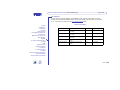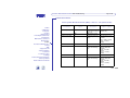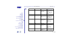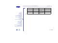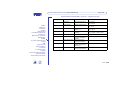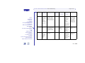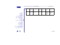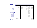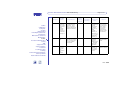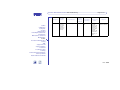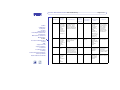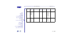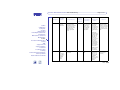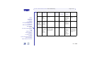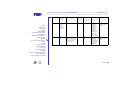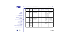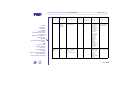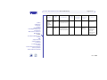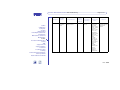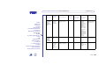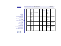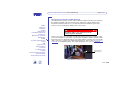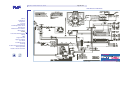
1
P o w e r D i s t r i b u t i o n U n i t PDU Troubleshooting
Page 1 of 54
PDU Troubleshooting
The PDU Troubleshooting topic contains the following items:
Cables
Calibration
Computer
Cooling
DIB Interface
Field Replaceable Units
Instruments
Maintenance Software
Manipulator
Power
Preventive Maintenance
Safety
SMC
Support Board
Support Cabinet
Test Head
Troubleshooting
Training
Product Integration Manuals
Site Prep Guide
Install & Checkout Guide
HOME
HELP
• Test Points
• Maintenance Signals
• Connector Pinouts
• Troubleshooting Table
• PDU Interlock Switch Troubleshooting
• PDU Electrical Schematic
Note
For additional information about the PDU, refer to the Troubleshooting Guide.
Rev. 0406
P o w e r D i s t r i b u t i o n U n i t PDU Troubleshooting
Page 2 of 54
Test Points
Test points for various voltages are available on the exterior of the PDU. The test
points are current limited and scaled to a low level voltage. All test points are accurate
to +/- 2 percent of actual. See the Test Point Signals table.
Cables
Calibration
Computer
Cooling
DIB Interface
Field Replaceable Units
Instruments
Maintenance Software
Manipulator
Power
Preventive Maintenance
Safety
SMC
Support Board
Support Cabinet
Test Head
Troubleshooting
Training
Product Integration Manuals
Site Prep Guide
Install & Checkout Guide
HOME
HELP
Test Point Signals
Test Point Signal
Description
Scale
Expected Range
Input AC Voltage
Proportional AC voltage to input
AC voltage
100:1
0 to 5.3 Vrms
Output AC Voltage
Proportional AC voltage to output
AC voltage
100:1
0 to 2.3 Vrms
Output DC Voltage
Proportional DC voltage to output
DC voltage
10:1
0 to 10.0 VDC
Control AC Voltage
Wired directly to AC control
voltage
1:1
0 to 28 Vrms
Control DC Voltage
Wired directly to DC control
voltage
1:1
0 to 28 VDC
Rev. 0406
P o w e r D i s t r i b u t i o n U n i t PDU Troubleshooting
Page 3 of 54
Maintenance Signals
An amber maintenance light on the PDU indicates that the PDU controller watchdog
timer has timed out and flashes various two-digit trouble codes for troubleshooting
purposes when overtemperature or fan failure events have occurred.
Cables
Calibration
Computer
Cooling
DIB Interface
Field Replaceable Units
Instruments
Maintenance Software
Manipulator
Power
Preventive Maintenance
Safety
SMC
Support Board
Support Cabinet
Test Head
Troubleshooting
Training
Product Integration Manuals
Site Prep Guide
Install & Checkout Guide
HOME
HELP
Fan failure (various fans are distributed throughout the system), overtemperature (of
various locations) , and processor malfunction (on the controller module) are the three
implemented maintenance signals.
The timing/duration of each pulse (defined as a flash of the LED or presence of the
MAINT output signal on J66 of the SMC) in the two-digit trouble code is as follows:
• Pulse duration is typically 600 ms
• Pause between digits is typically 1000 ms
• Pause between pulses within a digit is typically 500 ms
• Pause between successive trouble codes is typically 2000 ms
The specific trouble code indications are:
• A solid LED (not flashing) or constant HIGH output signal indicates that a PDU
microprocessor reset is required.
• A single pulse for the first digit indicates a fan failure. The number of pulses (1- 10)
for the second digit indicate the failed fan unit. Two pulses for the first digit indicates
and overtemperature condition. The number of pulses (1- 3) for the second digit
indicate the overtemperature sensor number.
Rev. 0406
P o w e r D i s t r i b u t i o n U n i t PDU Troubleshooting
Page 4 of 54
Connector Pinouts
Tester System Monitor/Controller (SMC) connector – J66 (25 Pin D-sub)
Pin Number
Cables
Calibration
Computer
Cooling
DIB Interface
Field Replaceable Units
Instruments
Maintenance Software
Manipulator
Power
Preventive Maintenance
Safety
SMC
Support Board
Support Cabinet
Test Head
Troubleshooting
Training
Product Integration Manuals
Site Prep Guide
Install & Checkout Guide
HOME
HELP
Signal
Description
1 (return on pin 14)
48 V_ON
15 KHz signal that
commands the 48V buss
to turn on
2
GND
SMC Chassis ground
3 (return on any COM)
V1
Proportional frequency
to DC voltage, load side
of F4*
4
COM
SMC common
5 (return on any COM)
I1
Proportional frequency
to DC current through
F4*
6
COM
SMC common
7 (return on any COM)
I2
Proportional frequency
to DC current through
F5*
Specification
(input – output)
5V, squarewave
15KHz (± 2%)
5V, squarewave, 10 mV/
Hz 0V – 100Hz (-0Hz,
+100Hz)
48V – 4.9KHz (± 100 Hz)
100V – 10.1 KHz (±
100Hz)
5V, squarewave, 15 mA/
Hz 0A – 100Hz (-0Hz,
+200Hz)
130A – 8.77 KHz (±
200Hz)
150 A – 10.1 KHz (±
200Hz)
5V, squarewave, 15 mA/
Hz 0A – 100Hz (-0Hz,
+200Hz)
130A – 8.77 KHz (±
200Hz)
150 A – 10.1 KHz (±
200Hz)
Rev. 0406
P o w e r D i s t r i b u t i o n U n i t PDU Troubleshooting
Pin Number
Cables
Calibration
Computer
Cooling
DIB Interface
Field Replaceable Units
Instruments
Maintenance Software
Manipulator
Power
Preventive Maintenance
Safety
SMC
Support Board
Support Cabinet
Test Head
Troubleshooting
Training
Product Integration Manuals
Site Prep Guide
Install & Checkout Guide
HOME
HELP
Signal
Page 5 of 54
Description
8 (return on any COM)
Vac
Proportional frequency
to AC output voltage,
phase A to C
9
COM
SMC common
10 (return on any COM)
MAINT
Pattern of TTL signals
indicating what type of
maintenance is required
Specification
(input – output)
5V, squarewave, 25 mV/
Hz 0V – 100Hz (-0Hz,
+100Hz)
208V – 8.42 KHz (±
100Hz)
250V – 10.1 KHz (±
100Hz)
5V, squarewave
Digit 1 (.6S on, .5S off)
1 Fan Failure
2 Over temperature
1S off between digits
Digit 2 (.6S on, .5S off)
1-10 Failed Item Number
2S between trouble
codes
11 (return on pin 23)
+5V
Supply voltage for all
signals on J66
12
GND
SMC Chassis ground
13 (return on pin 25)
K1_ON
15 KHz signal that
commands the Test
Power AC outputs to turn
on
14
ON_RTN_48V
Return for 48V buss turn
on signal
15
GND
SMC Chassis ground
5VDC (± 5%)
5V, squarewave
15KHz (± 2%)
Rev. 0406
P o w e r D i s t r i b u t i o n U n i t PDU Troubleshooting
Pin Number
Cables
Calibration
Computer
Cooling
DIB Interface
Field Replaceable Units
Instruments
Maintenance Software
Manipulator
Power
Preventive Maintenance
Safety
SMC
Support Board
Support Cabinet
Test Head
Troubleshooting
Training
Product Integration Manuals
Site Prep Guide
Install & Checkout Guide
HOME
HELP
Signal
Page 6 of 54
Description
Specification
(input – output)
16 (return on any COM)
V0
Proportional frequency
to DC voltage, line side
of F4 and F5*
5V, squarewave, 10 mV/
Hz 0V – 100Hz (-0Hz,
+100Hz)
48V – 4.9KHz (± 100 Hz)
100V – 10.1 KHz (±
100Hz)
17
COM
SMC common
18 (return on any COM)
V2
Proportional frequency
to DC voltage, load side
of F5*
5V, squarewave, 10 mV/
Hz 0V – 100Hz (-0Hz,
+100Hz)
48V – 4.9KHz (± 100 Hz)
100V – 10.1 KHz (±
100Hz)
19 (return on any COM)
Vab
Proportional frequency
to AC output voltage,
phase A to B
5V, squarewave, 25 mV/
Hz 0V – 100Hz (-0Hz,
+100Hz)
208V – 8.42 KHz (±
100Hz)
250V – 10.1 KHz (±
100Hz)
20
COM
SMC common
21 (return on any COM)
Vbc
Proportional frequency
to AC output voltage,
phase B to C
5V, squarewave, 25 mV/
Hz 0V – 100Hz (-0Hz,
+100Hz)
208V – 8.42 KHz (±
100Hz)
250V – 10.1 KHz (±
100Hz)
22 (return on any COM)
FREQ
Squarewave signal
indicating AC line
frequency
5V, squarewave
50 Hz ± 3Hz – 50Hz (± 1%)
60 Hz ± 3Hz – 60Hz (± 1%)
Rev. 0406
P o w e r D i s t r i b u t i o n U n i t PDU Troubleshooting
Pin Number
Cables
Calibration
Computer
Cooling
DIB Interface
Field Replaceable Units
Instruments
Maintenance Software
Manipulator
Power
Preventive Maintenance
Safety
SMC
Support Board
Support Cabinet
Test Head
Troubleshooting
Training
Product Integration Manuals
Site Prep Guide
Install & Checkout Guide
HOME
HELP
Signal
Page 7 of 54
Description
23
5VRTN
Return for signal voltage
power supply
24
GND
SMC Chassis ground
25
ON_RTN_K1
Return for the Test
Power AC outputs turn
on signal
Specification
(input – output)
* Refer to schematic drawing D-5 and D-6 and layout drawing number D-2, D-3, and D-4 for location of these components.
Rev. 0406
P o w e r D i s t r i b u t i o n U n i t PDU Troubleshooting
Page 8 of 54
System Interface Panel LEDs connector – J65 (9 Pin D-sub)
Pin Number
Cables
Calibration
Computer
Cooling
DIB Interface
Field Replaceable Units
Instruments
Maintenance Software
Manipulator
Power
Preventive Maintenance
Safety
SMC
Support Board
Support Cabinet
Test Head
Troubleshooting
Training
Product Integration Manuals
Site Prep Guide
Install & Checkout Guide
HOME
HELP
Signal
Description
Specification
1
PWR_AVAIL
High when input power is
available to the PDU
5V (± .5V), On
0V (± .5V), Off
2
TEST_PWR_ON
High when the Test Power
contactor has pulled in.
5V (± .5V), On
0V ± .5V, Off
3
MAIN_PWR_ON
High when the main input
breaker is on.
5V (± .5V), On
0V (± .5V), Off
4
48V_ENERGIZED
Voltage proportional to the
48V buss.
3.5V (± .5V @ 20Ω resistive) – 48VDC
0V (± .5V @ 20Ω resistive) – 0VDC
5
N/C
6
PWR_AVAIL_RTN
Return for the signal
indicating input power is
available
7
TEST_PWR_ON_RTN
Return for the signal
indicating the Test Power AC
contactor has pulled in
8
MAIN_PWR_ON_RTN
Return for the signal
indicating the main input
breaker is on
9
48V_ENERGIZED_RTN
Return for the voltage
proportional the 48V buss.
Rev. 0406
P o w e r D i s t r i b u t i o n U n i t PDU Troubleshooting
Page 9 of 54
Troubleshooting Table
Use the troubleshooting table, and refer to the PDU Electrical Schematic. Also refer to
the drawings and schematics in the Teal PDU Manual.
Test equipment (properly calibrated) required:
Cables
Calibration
Computer
Cooling
DIB Interface
Field Replaceable Units
Instruments
Maintenance Software
Manipulator
Power
Preventive Maintenance
Safety
SMC
Support Board
Support Cabinet
Test Head
Troubleshooting
Training
Product Integration Manuals
Site Prep Guide
Install & Checkout Guide
HOME
HELP
• DMM with RMS features (Fluke 87 or equivalent)
• Clamp-on, general-purpose ammeter (able to measure up to 350A)
• Temperature measuring device (able to measure up to 150 degrees C)
• Digital storage oscilloscope with isolated channel inputs (Tektronix THS720A or
equivalent)
• Current probe, suitable for connection to oscilloscope: 10A range or higher, 10
MHz BW (for measuring gate signals)
• Current probe, suitable for connection to oscilloscope: 200A range or higher,
capable of measuring 47-63 Hz currents that are DC biased (for measuring current
into SCRs)
For all AC voltages, input to unit is specified to +10%, -15% of nominal rating. All other
AC voltages within the PDU will vary proportionally with the input voltage that is
present. Unless otherwise indicated below, you should see AC voltages +/-2% of the
expected value after correcting for any non-nominal input voltage.
Note
The seven-digit part numbers with no hyphens are Teal part numbers.
Rev. 0406
P o w e r D i s t r i b u t i o n U n i t PDU Troubleshooting
Page 10 of 54
Note
The seven-digit part numbers with no hyphens are Teal part numbers.
Cables
Calibration
Computer
Cooling
DIB Interface
Field Replaceable Units
Instruments
Maintenance Software
Manipulator
Power
Preventive Maintenance
Safety
SMC
Support Board
Support Cabinet
Test Head
Troubleshooting
Training
Product Integration Manuals
Site Prep Guide
Install & Checkout Guide
HOME
HELP
Symptom
AC output
voltage too
high or low
Possible
Cause
Determination
Input
Power
During
Check
Reference
Schematic/
Drawing
Reference
Designator/
Value
Solution
AC input
voltage
provided to
PDU is too
high or too
low.
Measure input voltage.
ON
Tap change
board and/or
sheet V-1
Check input
voltage at test
points, should
be +10% to 15% of
expected
voltage divided
by 100
Re-tap distribution
transformer or reconfigure tap
change board to
match source
voltage
Main
transformer
incorrectly
tapped
Measure input voltage
and compare to the tap
configuration
ON
Tap change
board and/or
sheet V-1
Check input
voltage at test
points, should
be +10% to 15% of
expected
voltage divided
by 100
Re-configure tap
change board to
match source
voltage. (See tap
change diagram on
tap cover board)
Loose
connection at
input breaker
or tap change
board
Inspect connections for
proper torque
OFF
D-3, D-5, V-1
CB1 Input lug
torque = 50 inlbs, output lug
torque = 120 in
lbs. Tap change
board lug
torque = 50 inlbs
Tighten connection
at effected locations
to specified torque
Rev. 0406
P o w e r D i s t r i b u t i o n U n i t PDU Troubleshooting
Symptom
Cables
Calibration
Computer
Cooling
DIB Interface
Field Replaceable Units
Instruments
Maintenance Software
Manipulator
Power
Preventive Maintenance
Safety
SMC
Support Board
Support Cabinet
Test Head
Troubleshooting
Training
Product Integration Manuals
Site Prep Guide
Install & Checkout Guide
HOME
HELP
No voltage
present on
Unswitched
AC output
Possible
Cause
Determination
Page 11 of 54
Input
Power
During
Check
Reference
Schematic/
Drawing
Reference
Designator/
Value
Solution
No input
voltage
present
Measure input voltage at
test points
ON
D-2
Check input
voltage at test
points, should
be +10% to 15% of
expected
voltage divided
by 100
Check and repair
AC service
Input CB1
tripped or off
Visual inspection
ON
D-2, D-5
CB1
Turn on input CB1
Branch
breaker
tripped or off
Visual inspection
ON
D-2, D-5
CB4 - CB9
Check for overload
problem, reset
tripped branch
breaker
Loose
connection
between
transformer
secondary 1
and output
CB4-CB9
Visual inspection and/or
continuity check on
effected circuit
OFF
D-2, D-5
Wire #'s 6-8,
CB4-CB9
Tighten connections
between main transformer secondary 1
and CB
Loose
connection
between
output CB
and
receptacles
Visual inspection and/or
continuity check on
effected circuit
Check bus bar
connections at
inputs to breakers
OFF
D-2, D-5
CB4-CB9, J54J62 (see
distribution
schematic for
wire #'s)
Tighten connections
on effected
receptacle or CB
Rev. 0406
P o w e r D i s t r i b u t i o n U n i t PDU Troubleshooting
Symptom
Cables
Calibration
Computer
Cooling
DIB Interface
Field Replaceable Units
Instruments
Maintenance Software
Manipulator
Power
Preventive Maintenance
Safety
SMC
Support Board
Support Cabinet
Test Head
Troubleshooting
Training
Product Integration Manuals
Site Prep Guide
Install & Checkout Guide
HOME
HELP
Possible
Cause
Determination
Page 12 of 54
Input
Power
During
Check
Reference
Schematic/
Drawing
Reference
Designator/
Value
Solution
24V power
supply failure
Check power supply
input/output voltage at
test points
ON
D-2, D-3, D-5
Input voltage
between test
points "24VAC"
and “N” should
be 20-28 VAC,
Output voltage
between
"24VDC" test
point and "N"
test point
should be 2228 VDC
Replace power
supply REG1 PN
361-154-00
Failed output
circuit
breaker
Perform visual/operational
inspection, and/or voltage
check at output circuit
breakers.
ON
D-2, D-5
CB4-CB9 input
voltage should
be 120VAC
from any
terminal to case
ground. Output
voltage should
match input
when breaker is
"on", should be
zero when
breaker is
"tripped" or "off"
Replace circuit
breaker CB4-CB6
PN 523-354-16 or
CB7-CB9 PN 522995-16
Control
Circuit
breaker
failure
Perform visual/operational
inspection, and/or voltage
check at input/output of
control circuit breakers
ON
D-2, D-5,
Check for
normal
operation of
circuit breakers
by measuring
input and
output from
breaker CB2
and CB3
Reset or replace
circuit breaker CB2
PN 522-995-02 or
CB3 PN 523-354-04
Rev. 0406
P o w e r D i s t r i b u t i o n U n i t PDU Troubleshooting
Symptom
Cables
Calibration
Computer
Cooling
DIB Interface
Field Replaceable Units
Instruments
Maintenance Software
Manipulator
Power
Preventive Maintenance
Safety
SMC
Support Board
Support Cabinet
Test Head
Troubleshooting
Training
Product Integration Manuals
Site Prep Guide
Install & Checkout Guide
HOME
HELP
No voltage
present on
Switched
AC output
Possible
Cause
Determination
Page 13 of 54
Input
Power
During
Check
Reference
Schematic/
Drawing
Reference
Designator/
Value
Solution
Control
transformer
failure
Check voltages at input
and output of control
transformer.
CB2 may trip if T2 has an
internal short. If CB3 is
off when this happens, T2
failure is the likely cause.
ON
D-3, D-5
T2 input voltage
should be
+10% to -15%
of expected
input voltage
between wire
#s 94 & 95.
Output should
be 24VAC
between wire
#'s 96 & 97
Replace control
transformer T2 PN
541-242-00
Failed output
receptacle
Visually inspect
receptacle and/or perform
continuity check on each
receptacle between
terminals and slots
OFF
D-2, D-5
J54-J62
Replace receptacle
J58-J62 PN 358092-00 or J54-J57
PN 351-240-01
Failed EMI/
RFI filter
Compare voltage at input/
output of EMI/RFI filter
ON
D-3, D-5
Voltage at filter
output should
match voltage
at filter input
Replace EMI/RFI
filter P/N 521-35300
F1, F2, or F3
fuses are
blown or bad
connection to
Phase
Controller
Assembly
connector J4.
Check fuses and inspect
for possible causes of
blown fuses. Check
power to J4 of Phase
Controller Assembly.
OFF/ON
D-3, D-5
Perform
continuity check
on fuses.
There should
be 120VAC
+10/-15% at J4,
between pins 14, 2-4, 3-4.
Replace fuse(s) F1,
F2, or F3 (any one
or all) PN 471-59601. Repair loose or
broken connections
to Phase Controller
Assembly
Branch
breaker
tripped or off
Visual inspection
ON
D-2, D-5
CB10-CB12
Check for overload
problem, reset
tripped branch
breaker
Rev. 0406
P o w e r D i s t r i b u t i o n U n i t PDU Troubleshooting
Symptom
Cables
Calibration
Computer
Cooling
DIB Interface
Field Replaceable Units
Instruments
Maintenance Software
Manipulator
Power
Preventive Maintenance
Safety
SMC
Support Board
Support Cabinet
Test Head
Troubleshooting
Training
Product Integration Manuals
Site Prep Guide
Install & Checkout Guide
HOME
HELP
Possible
Cause
Determination
Page 14 of 54
Input
Power
During
Check
Reference
Schematic/
Drawing
Reference
Designator/
Value
Solution
Externally
supplied
15Khz signal
not within
specifications
(J66)
Measure 15Khz control
signal at J9, Pins 24-25 of
Phase Controller
Assembly.
ON
D-2, D-6
Must be 15Khz
square wave +/2%, 50% duty
cycle, +/-2%,
TTL level
Repair signal source
(External to PDU)
Contactor coil
defective
24VDC control voltage
present at coil but
contactor not pulled in
ON
D-3, D-5
Check for
24VDC at input
to CON1 wire
#'s 72 & 73
Replace contactor
CON1 PN 361-07600
Control
power not
present due
to tripped
control circuit
breakers
Visual Inspection of CB's
ON
D-2, D-5
CB2, CB3
Reset circuit breaker
CB2, CB3
Control
Circuit
breaker
failure
Perform visual/operational
inspection, and/or voltage
check at input/output of
control circuit breakers
ON
D-2, D-5
Check for
normal
operation of
circuit breakers
by measuring
input and
output from
breaker CB2
and CB3
Reset or replace
circuit breaker CB2
PN 522-995-02 or
CB3 PN 523-354-04
Rev. 0406
P o w e r D i s t r i b u t i o n U n i t PDU Troubleshooting
Symptom
Cables
Calibration
Computer
Cooling
DIB Interface
Field Replaceable Units
Instruments
Maintenance Software
Manipulator
Power
Preventive Maintenance
Safety
SMC
Support Board
Support Cabinet
Test Head
Troubleshooting
Training
Product Integration Manuals
Site Prep Guide
Install & Checkout Guide
HOME
HELP
Possible
Cause
Determination
Page 15 of 54
Input
Power
During
Check
Reference
Schematic/
Drawing
Reference
Designator/
Value
Solution
Loose or
poor control
circuit
connection
Visual/continuity
inspection:
OFF
D-3, D-4, D-5,
D-6
Phase
Controller
Assembly J3 to
contactor, SMC
connector to
Phase
Controller
Assembly J9
(RC3), power
source to
Phase
Controller
Assembly J4
Repair loose
connection in control
path
Loose or
poor power
circuit
connection
Visual inspection and/or
continuity check on
effected circuit
OFF
D-3, D-5
T1 to CON1,
CON1 CB10CB12, CB10CB12 to J50J53 (see
distribution
schematic for
wire #'s)
Tighten effected
connections
between transformer
secondary and
output receptacles
24V power
supply failure
Check power supply
input/output voltage at
test points
ON
D-2, D-3, D-5
Input voltage
between test
points "24VAC"
and “N” should
be 20-28 VAC,
Output voltage
between
"24VDC" test
point and "N"
test point
should be 2228 VDC
Replace power
supply REG1 PN
361-154-00
Rev. 0406
P o w e r D i s t r i b u t i o n U n i t PDU Troubleshooting
Symptom
Cables
Calibration
Computer
Cooling
DIB Interface
Field Replaceable Units
Instruments
Maintenance Software
Manipulator
Power
Preventive Maintenance
Safety
SMC
Support Board
Support Cabinet
Test Head
Troubleshooting
Training
Product Integration Manuals
Site Prep Guide
Install & Checkout Guide
HOME
HELP
Possible
Cause
Determination
Page 16 of 54
Input
Power
During
Check
Reference
Schematic/
Drawing
Reference
Designator/
Value
Solution
Failed output
circuit
breaker
Perform visual/operational
inspection, and/or voltage
check at output circuit
breakers.
ON
D-2, D-5
CB10-CB12
input voltage
should be
120VAC from
any terminal to
case ground.
Output voltage
should match
input when
breaker is "on",
should be zero
when breaker is
"tripped" or "off"
Replace circuit
breaker CB10-CB11
PN 522-995-16 or
CB12 PN 523-35516
Phase
Controller
Assembly
defective
Check for proper output
voltage to AC contactor
coil.
ON
D-3, D-4, D-5,
D-6
With a proper
15kHZ signal
applied, Phase
Controller
Assembly J3,
pin 1-3 should
be
approximately
24V DC
Replace Phase
Controller Assembly
PN 361-157-00
Failed output
receptacle
Visually inspect
receptacle and/or perform
continuity check on each
receptacle between
terminals and slots
OFF
D-2, D-5
J50-J53
Replace receptacle
J52-J53 PN 351240-00 or J50 PN
351-358-00 or J51
PN 4990334
Failed EMI/
RFI filter
Compare voltage at input/
output of EMI/RFI filter
ON
D-3, D-5
Voltage at filter
output should
match voltage
at filter input
Replace EMI/RFI
filter P/N 521-35300
Rev. 0406
P o w e r D i s t r i b u t i o n U n i t PDU Troubleshooting
Symptom
Cables
Calibration
Computer
Cooling
DIB Interface
Field Replaceable Units
Instruments
Maintenance Software
Manipulator
Power
Preventive Maintenance
Safety
SMC
Support Board
Support Cabinet
Test Head
Troubleshooting
Training
Product Integration Manuals
Site Prep Guide
Install & Checkout Guide
HOME
HELP
DC output
voltage too
high or too
low or
erratic
Possible
Cause
Determination
Page 17 of 54
Input
Power
During
Check
Reference
Schematic/
Drawing
Reference
Designator/
Value
Solution
Control
transformer
failure
Check voltages at input
and output of control
transformer
ON
D-3, D-5
T2 input voltage
should be
+10% to -15%
of expected
input voltage
between wire
#s 94 & 95.
Output should
be 20-28 VAC
between wire
#'s 96 & 97
Replace control
transformer T2 PN
541-242-00
AC Input
voltage out of
range
Measure AC input voltage
ON
D-2, V-1
Input voltage at
test points
should be
+10% to -15%
of expected
voltage divided
by 100
Correct source or
select other PDU tap
Feedback
voltage
connection
problem
between
Phase
Controller
Assembly
and DC
output
Check continuity
OFF
D-3, D-4, D-5,
D-6
Phase
Controller
Assembly J1
wire #'s 177178, 180-181 to
DC output
Correct wire
connection problem
to J1 of Phase
Controller Assembly.
Rev. 0406
P o w e r D i s t r i b u t i o n U n i t PDU Troubleshooting
Symptom
Cables
Calibration
Computer
Cooling
DIB Interface
Field Replaceable Units
Instruments
Maintenance Software
Manipulator
Power
Preventive Maintenance
Safety
SMC
Support Board
Support Cabinet
Test Head
Troubleshooting
Training
Product Integration Manuals
Site Prep Guide
Install & Checkout Guide
HOME
HELP
Possible
Cause
Determination
Page 18 of 54
Input
Power
During
Check
Reference
Schematic/
Drawing
Reference
Designator/
Value
Solution
Poor
connection
from Gate
Drive
Assembly to
SCR
modules
Check continuity and
visually inspect connector
pins
OFF
D-4, D-5, D-6
Gate Drive
Assembly J2,
J11, J12 (see
schematic for
wire #'s)
Reseat or repair
cables as necessary
Poor
connection
from Phase
Controller
Assembly to
Gate Drive
Assembly
Check continuity and
visually inspect connector
pins
OFF
D-3, D-4, D-5,
D-6
Phase
Controller
Assembly J10
to Gate Drive
AssemblyJ1,
Phase
Controller
Assembly J31
to Gate Drive
AssemblyJ5,
Phase
Controller
Assembly J32
to Gate Drive
AssemblyJ9,
Reseat or repair
cables as necessary
Rev. 0406
P o w e r D i s t r i b u t i o n U n i t PDU Troubleshooting
Symptom
Cables
Calibration
Computer
Cooling
DIB Interface
Field Replaceable Units
Instruments
Maintenance Software
Manipulator
Power
Preventive Maintenance
Safety
SMC
Support Board
Support Cabinet
Test Head
Troubleshooting
Training
Product Integration Manuals
Site Prep Guide
Install & Checkout Guide
HOME
HELP
Possible
Cause
Determination
Page 19 of 54
Input
Power
During
Check
Reference
Schematic/
Drawing
Reference
Designator/
Value
Solution
F1,F2, F3 or
F6 fuses are
blown or bad
connection to
Phase
Controller
Assembly
connector J4
or Gate Drive
Assembly J3
Check fuses and inspect
for possible causes of
blown fuses. Check
power to J4 of Phase
Controller Assembly and
to Gate Drive Assembly
J3
OFF
D-2, D-5
Perform
continuity check
on fuses.
There should
be 120VAC
+10/-15% at
Phase
Controller
Assembly J4,
between pins 14, 2-4, 3-4, and
at Gate Drive
Assembly J3.
Replace fuse F1,
F2, F3, or F6 (any
one or all) PN 471596-01. Repair
loose or broken
connections to
Phase Controller
Assembly or Gate
Drive Assembly
Failed power
SCR
Measure input current to
each SCR using current
probe/oscilloscope.
Access to wires can be
had at glastic terminal
board.
ON
D-4, D-5, D-6
Current wave
shape should
be similar to
Figure 1.
Amplitude will
vary with
applied load.
Replace Heat Sink
Assembly PN 361156-00
Loose or
poor
connection
from SCR to
Inductor to
Capacitor
bank to
output
Visually inspect
connections
OFF
Check for
tightness from
Bar3 to L1 to
Bar5 to F4-F5
to CONN3CONN4 +, and
Bar2 to Bar6 to
CONN3 &
CONN4 -
Tighten or repair
connections as
necessary
Figure 1,
Theory of
operation.
D-3, D-4, D-5,
D-6
Rev. 0406
P o w e r D i s t r i b u t i o n U n i t PDU Troubleshooting
Symptom
Possible
Cause
Bad power
connector
Cables
Calibration
Computer
Cooling
DIB Interface
Field Replaceable Units
Instruments
Maintenance Software
Manipulator
Power
Preventive Maintenance
Safety
SMC
Support Board
Support Cabinet
Test Head
Troubleshooting
Training
Product Integration Manuals
Site Prep Guide
Install & Checkout Guide
HOME
HELP
Determination
Visually inspect
connectors
Page 20 of 54
Input
Power
During
Check
OFF
Reference
Schematic/
Drawing
D-3, D-5
Reference
Designator/
Value
Check CONN3
& CONN4 for
proper contact
mating and/or
cracked
housings
Solution
Replace connector
CONN3 and/or
CONN4 PN
4990346
Rev. 0406
P o w e r D i s t r i b u t i o n U n i t PDU Troubleshooting
Symptom
Cables
Calibration
Computer
Cooling
DIB Interface
Field Replaceable Units
Instruments
Maintenance Software
Manipulator
Power
Preventive Maintenance
Safety
SMC
Support Board
Support Cabinet
Test Head
Troubleshooting
Training
Product Integration Manuals
Site Prep Guide
Install & Checkout Guide
HOME
HELP
Possible
Cause
Phase
Controller
Assembly
malfunction
Determination
Check for proper gate
control signals Using
oscilloscope that has isolated inputs to channels:
(Ensure Tester SMC
connector is connected)
Page 21 of 54
Input
Power
During
Check
ON
Reference
Schematic/
Drawing
Reference
Designator/
Value
D-3, D-4, D-5,
D-6
See Theory of
Operation,
Figure 4 and 5
Sync channel 1
of scope to a
power reference sine wave
such as the output of the control transformer
T2.
Solution
Replace Phase
Controller Assembly
PN 361-157-00
Observe on
channel 2:
Phase
Controller
Assembly J31,
pins
1,3,5,7,9,11 (for
gates 1-6
respectively) &
J32, pins
1,3,5,7,9,11 (for
gates 7-12
respectively),
pin 2 is
common in any
case, you
should see a
low level
square wave
(3-5Vpk) that is
locked in phase
to the power
line reference.
Gates 1-6- See
Figure 4, Gates
7-12- See
Figure 5.
Rev. 0406
P o w e r D i s t r i b u t i o n U n i t PDU Troubleshooting
Symptom
Gate Drive
Assembly
malfunction
Cables
Calibration
Computer
Cooling
DIB Interface
Field Replaceable Units
Instruments
Maintenance Software
Manipulator
Power
Preventive Maintenance
Safety
SMC
Support Board
Support Cabinet
Test Head
Troubleshooting
Training
Product Integration Manuals
Site Prep Guide
Install & Checkout Guide
HELP
Determination
Once Phase Controller
Assembly has been
eliminated as a problem
source put a current
probe onto each gate
cathode wire and
measure gate pulse
current.
Input
Power
During
Check
ON
Reference
Schematic/
Drawing
D-3, D-4, D-5,
D-6
See Theory of
Operation,
figure 2 and 3,
for a depiction
of a normal
gate pulses.
Reference
Designator/
Value
Sync channel 1
of scope to a
power reference sine wave
such as the output of the control transformer
T2.
Solution
Replace Gate Drive
Assembly PN 361155-00. It could also
be a bad connection
to a gate pin, or an
open gate within the
SCR
Check Gate
Drive Assembly
J2 wire #'s 298,
300, 302, 304,
306, 308, J11
wire #'s 310,
312, 314 & J12
wire #'s 316,
318, 320 for
current pulses.
Current pulses
should be like
those in Figure
2 and 3 and
locked in phase
to the power
line reference.
DC output
ripple
excessive
HOME
Possible
Cause
Page 22 of 54
Bad D7 diode
Continuity check
OFF
D-3, D-5
Disconnect one
lead of D7 and
check for open /
short using an
ohmmeter
Replace diode D7
PN 4990367
Failed ripple
capacitor
Visual inspection for
venting
OFF
D-3, D-5
Check C1-C6
for fluid leaking.
Replace capacitor
C1-C6 (any or all)
PN 131-428-00
Rev. 0406
P o w e r D i s t r i b u t i o n U n i t PDU Troubleshooting
Symptom
Cables
Calibration
Computer
Cooling
DIB Interface
Field Replaceable Units
Instruments
Maintenance Software
Manipulator
Power
Preventive Maintenance
Safety
SMC
Support Board
Support Cabinet
Test Head
Troubleshooting
Training
Product Integration Manuals
Site Prep Guide
Install & Checkout Guide
HOME
HELP
Possible
Cause
Determination
Page 23 of 54
Input
Power
During
Check
Reference
Schematic/
Drawing
Reference
Designator/
Value
Solution
F1,F2, F3 or
F6 fuses are
blown or bad
connection to
Phase
Controller
Assembly
connector J4
or Gate Drive
Assembly J3
Check fuses and inspect
for possible causes of
blown fuses. Check
power to J4 of Phase
Controller Assembly and
to Gate Drive Assembly
J3
OFF
D-3, D-5
Perform
continuity check
on fuses.
There should
be 120VAC
+10/-15% at
Phase
Controller
Assembly J4,
between pins 14, 2-4, 3-4, and
at Gate Drive
Assembly J3.
Replace fuse F1,
F2, F3 or F6 (any
one or all) PN 471596-01. Repair
loose or broken
connections to
Phase Controller
Assembly or Gate
Drive Assembly
Failed Power
SCR
Measure input current to
each SCR using current
probe. Access to wires
can be had at glastic
terminal board.
ON
D-3, D-6
Current
waveshape
should be
similar to Figure
1. Amplitude
will vary with
applied load.
Replace Heat Sink
Assembly PN 361156-00
Poor
connection
from Gate
Drive
Assembly to
SCR
modules
Check continuity
OFF
D-3, D-4, D-6
Gate Drive
Assembly J2,
J11, J12 (see
schematic for
wire #'s)
Reseat or repair
cables as necessary
Rev. 0406
P o w e r D i s t r i b u t i o n U n i t PDU Troubleshooting
Symptom
Cables
Calibration
Computer
Cooling
DIB Interface
Field Replaceable Units
Instruments
Maintenance Software
Manipulator
Power
Preventive Maintenance
Safety
SMC
Support Board
Support Cabinet
Test Head
Troubleshooting
Training
Product Integration Manuals
Site Prep Guide
Install & Checkout Guide
HOME
HELP
Possible
Cause
Poor
connection
from Phase
Controller
Assembly to
Gate Drive
Assembly
Determination
Check continuity
Page 24 of 54
Input
Power
During
Check
OFF
Reference
Schematic/
Drawing
D-3, D-4, D-5,
D-6
Reference
Designator/
Value
Phase
Controller
Assembly J31
to Gate Drive
Assembly J5
(RC5), Phase
Controller
Assembly J32
to Gate Drive
Assembly J9
(RC7),
Solution
Reseat or repair
cables as necessary
Rev. 0406
P o w e r D i s t r i b u t i o n U n i t PDU Troubleshooting
Symptom
Cables
Calibration
Computer
Cooling
DIB Interface
Field Replaceable Units
Instruments
Maintenance Software
Manipulator
Power
Preventive Maintenance
Safety
SMC
Support Board
Support Cabinet
Test Head
Troubleshooting
Training
Product Integration Manuals
Site Prep Guide
Install & Checkout Guide
HOME
HELP
Possible
Cause
Phase
Controller
Assembly
malfunction
Determination
Check for proper gate
control signals Using
oscilloscope that has isolated inputs to channels:
(Ensure Tester SMC
connector is connected)
Page 25 of 54
Input
Power
During
Check
ON
Reference
Schematic/
Drawing
Reference
Designator/
Value
D-3, D-4, D-5,
D-6
See Theory of
Operation,
figure 4 and 5,
for a depiction
of a normal
gate voltage
square waves.
Sync channel 1
of scope to a
power reference sine wave
such as the output of the control transformer
T2.
Solution
Replace Phase
Controller Assembly
PN 361-157-00
Observe on
channel 2:
Phase
Controller
Assembly J31,
pins
1,3,5,7,9,11 (for
gates 1-6
respectively) &
J32, pins
1,3,5,7,9,11 (for
gates 7-12
respectively),
pin 2 is
common in any
case, you
should see a
low level
square wave
(3-5Vpk) that is
locked in phase
to the power
line. Gates 16- See Figure 4,
Gates 7-12See Figure 5.
Rev. 0406
P o w e r D i s t r i b u t i o n U n i t PDU Troubleshooting
Symptom
Cables
Calibration
Computer
Cooling
DIB Interface
Field Replaceable Units
Instruments
Maintenance Software
Manipulator
Power
Preventive Maintenance
Safety
SMC
Support Board
Support Cabinet
Test Head
Troubleshooting
Training
Product Integration Manuals
Site Prep Guide
Install & Checkout Guide
Possible
Cause
Gate Drive
Assembly
malfunction
DC output
voltage not
present
Signal source
not within
specification
or missing.
Determination
Once Phase Controller
Assembly has been
eliminated as a problem
source put a current
probe onto each gate
cathode wire and
measure gate pulse
current.
15Khz DC-ON signal not
shown on controller LED.
Page 26 of 54
Input
Power
During
Check
ON
ON
Reference
Schematic/
Drawing
Reference
Designator/
Value
D-3, D-4, D-5,
D-6
4100019_020_
060_SCB, See
Theory of
Operation,
figure 2 and 3,
for a depiction
of a normal
gate pulses.
Sync channel 1
of scope to a
power reference sine wave
such as the output of the control transformer
T2.
D-2, D-3, D-4,
D-5, D-6
Check 15Khz
source from
SMC at 25 Pin
D-sub connector J9
Solution
Replace Gate Drive
Assembly PN 361155-00. It could also
be a bad connection
to a gate pin, or an
open gate within the
SCR
Check Gate
Drive Assembly
J2 wire #'s 298,
300, 302, 304,
306, 308, J11
wire #'s 310,
312, 314 & J12
wire #'s 316,
318, 320 for
current pulses.
Current pulses
should be like
those in Figure
2 and 3 and
locked in phase
to the power
line reference.
Repair source of signal (External to
PDU)
Must be 15Khz
square wave +/2%, 50% duty
cycle, +/-2%,
TTL level
HOME
HELP
Rev. 0406
P o w e r D i s t r i b u t i o n U n i t PDU Troubleshooting
Symptom
Cables
Calibration
Computer
Cooling
DIB Interface
Field Replaceable Units
Instruments
Maintenance Software
Manipulator
Power
Preventive Maintenance
Safety
SMC
Support Board
Support Cabinet
Test Head
Troubleshooting
Training
Product Integration Manuals
Site Prep Guide
Install & Checkout Guide
HOME
HELP
Possible
Cause
Determination
Page 27 of 54
Input
Power
During
Check
Reference
Schematic/
Drawing
Reference
Designator/
Value
Solution
F1,F2, F3 or
F6 fuses are
blown or bad
connection to
Phase
Controller
Assembly
connector J4
or Gate Drive
Assembly J3
Check fuses and inspect
for possible causes of
blown fuses. Check
power to J4 of Phase
Controller Assembly and
to Gate Drive Assembly
J3
OFF
D-3, D-5
Perform
continuity check
on fuses.
There should
be 120VAC
+10/-15% at
Phase
Controller
Assembly J4,
between pins 14, 2-4, 3-4, and
at Gate Drive
Assembly J3.
Replace fuse F1,
F2, F3, or F6 (any
one or all) PN 471596-01. Repair
loose or broken
connections to
Phase Controller
Assembly or Gate
Drive Assembly
Bad
connection
from Phase
Controller
Assembly J9
to SMC
connector
J66
Check cable connection
from SMC PDU connector
to Phase Controller
Assembly
OFF
D-2, D-3, D-4,
D-5, D-6
Check Phase
Controller
Assembly J9
ribbon cable for
proper
connection
(RC3)
Repair or replace
RC3 PN 4990372
DC Fuse(s)
blown
Continuity check.
Voltages V0, V1 and V2 to
SMC will not be equal. V0
is main DC bus and V1
and V2 are protected by
branch fuses within PDU
OFF
D-3, D-5
Perform
continuity check
on fuses F4
and/or F5.
Check load for
possible cause of
overload and
replace fuse F4 and/
or F5 PN 471-68800
Poor
connection
from Gate
Drive
Assembly to
SCR
modules
Check continuity
OFF
D-3, D-4, D-5,
D-6
Gate Drive
Assembly J2,
J11, J12 (see
schematic for
wire #'s)
Reseat or repair
cables as necessary
Rev. 0406
P o w e r D i s t r i b u t i o n U n i t PDU Troubleshooting
Symptom
Cables
Calibration
Computer
Cooling
DIB Interface
Field Replaceable Units
Instruments
Maintenance Software
Manipulator
Power
Preventive Maintenance
Safety
SMC
Support Board
Support Cabinet
Test Head
Troubleshooting
Training
Product Integration Manuals
Site Prep Guide
Install & Checkout Guide
HOME
HELP
Possible
Cause
Determination
Page 28 of 54
Input
Power
During
Check
Reference
Schematic/
Drawing
Reference
Designator/
Value
Solution
Poor
connection
from Phase
Controller
Assembly to
Gate Drive
Assembly
Check continuity
OFF
D-2, D-3, D-4,
D-5, D-6
Phase
Controller
Assembly J31
to Gate Drive
Assembly J5
(RC5), Phase
Controller
Assembly J32
to Gate Drive
Assembly J9
(RC7),
Reseat or repair
cables as necessary
Loose or
poor
connection to
AC input for
Phase
Controller
Assembly
Visually inspect connector
ON
D-3, D-4, D-5,
D-6
Check J4 on
Phase
Controller
Assembly for
solid
connections.
Repair connection.
Rev. 0406
P o w e r D i s t r i b u t i o n U n i t PDU Troubleshooting
Symptom
Cables
Calibration
Computer
Cooling
DIB Interface
Field Replaceable Units
Instruments
Maintenance Software
Manipulator
Power
Preventive Maintenance
Safety
SMC
Support Board
Support Cabinet
Test Head
Troubleshooting
Training
Product Integration Manuals
Site Prep Guide
Install & Checkout Guide
HOME
HELP
Possible
Cause
Phase
Controller
Assembly
malfunction
Determination
Check for proper gate
control signals Using
oscilloscope that has isolated inputs to channels:
(Ensure Tester SMC
connector is connected)
Page 29 of 54
Input
Power
During
Check
ON
Reference
Schematic/
Drawing
Reference
Designator/
Value
D-3, D-4, D-5,
D-6
See Theory of
Operation,
figure 4 and 5,
for a depiction
of a normal
gate voltage
square waves.
Sync channel 1
of scope to a
power reference sine wave
such as the output of the control transformer
T2.
Solution
Replace Phase
Controller Assembly
PN 361-157-00
Observe on
channel 2:
Phase
Controller
Assembly J31,
pins
1,3,5,7,9,11 (for
gates 1-6
respectively) &
J32, pins
1,3,5,7,9,11 (for
gates 7-12
respectively),
pin 2 is
common in any
case, you
should see a
low level
square wave
(3-5Vpk) that is
locked in phase
to the power
line. Gates 16- See Figure 4,
Gates 7-12See Figure 5.
Rev. 0406
P o w e r D i s t r i b u t i o n U n i t PDU Troubleshooting
Symptom
Cables
Calibration
Computer
Cooling
DIB Interface
Field Replaceable Units
Instruments
Maintenance Software
Manipulator
Power
Preventive Maintenance
Safety
SMC
Support Board
Support Cabinet
Test Head
Troubleshooting
Training
Product Integration Manuals
Site Prep Guide
Install & Checkout Guide
HOME
HELP
Possible
Cause
Gate Drive
Assembly
malfunction
Determination
Once Phase Controller
Assembly has been
eliminated as a problem
source put a current
probe onto each gate
cathode wire and
measure gate pulse
current.
Page 30 of 54
Input
Power
During
Check
ON
Reference
Schematic/
Drawing
Reference
Designator/
Value
D-3, D-4, D-5,
D-6 See Theory
of Operation,
figure 2 and 3,
for a depiction
of a normal
gate pulses.
Sync channel 1
of scope to a
power reference sine wave
such as the output of the control transformer
T2.
Solution
Replace Gate Drive
Assembly PN 361155-00. It could also
be a bad connection
to a gate pin, or an
open gate within the
SCR
Check Gate
Drive Assembly
J2 wire #'s 298,
300, 302, 304,
306, 308, J11
wire #'s 310,
312, 314 & J12
wire #'s 316,
318, 320 for
current pulses.
Current pulses
should be like
those in Figure
2 and 3 and
locked in phase
to the power
line reference.
Loose or
poor
connection
from SCR to
Inductor to
Capacitor
bank to
output
Visually inspect
connections
OFF
D-3, D-4, D-5,
D-6
Check for
tightness from
Bar3 to L1 to
Bar5 to F4-F5
to CONN3CONN4 +, and
Bar2 to Bar6 to
CONN3 &
CONN4 -
Tighten or repair
connections as
necessary
Rev. 0406
P o w e r D i s t r i b u t i o n U n i t PDU Troubleshooting
Symptom
Cables
Calibration
Computer
Cooling
DIB Interface
Field Replaceable Units
Instruments
Maintenance Software
Manipulator
Power
Preventive Maintenance
Safety
SMC
Support Board
Support Cabinet
Test Head
Troubleshooting
Training
Product Integration Manuals
Site Prep Guide
Install & Checkout Guide
HOME
HELP
When
turned off,
DC output
does not
reach 2V in
less than 10
Seconds
Possible
Cause
Determination
Page 31 of 54
Input
Power
During
Check
Reference
Schematic/
Drawing
Reference
Designator/
Value
Solution
Bad CONN3CONN4
power
connector
Visually inspect
connectors
OFF
D-3, D-5
Check CONN3
& CONN4 for
proper contact
mating and/or
cracked
housings
Replace connector
CONN3-CONN4 PN
4990346
Bad
connection
from Phase
Controller
Assembly to
Gate Drive
Assembly
Check continuity
OFF
D-3, D-4, D-5,
D-6
Phase
Controller
Assembly J10
to Gate Drive
Assembly J1
Repair or replace
cable
F1,F2, F3
fuses are
blown or bad
connection to
Phase
Controller
Assembly
connector J4
Check fuses and inspect
for possible causes of
blown fuses. Check
power to J4 of Phase
Controller Assembly
OFF
D-3, D-5
Perform
continuity check
on fuses.
There should
be 120VAC
+10/-15% at
Phase
Controller
Assembly J4,
between pins 14, 2-4, 3-4
Replace fuse F1,
F2, or F3 (any one
or all) PN 471-59601. Repair loose or
broken connections
to Phase Controller
Assembly
Rev. 0406
P o w e r D i s t r i b u t i o n U n i t PDU Troubleshooting
Symptom
Cables
Calibration
Computer
Cooling
DIB Interface
Field Replaceable Units
Instruments
Maintenance Software
Manipulator
Power
Preventive Maintenance
Safety
SMC
Support Board
Support Cabinet
Test Head
Troubleshooting
Training
Product Integration Manuals
Site Prep Guide
Install & Checkout Guide
HOME
HELP
Page 32 of 54
Determination
Input
Power
During
Check
Fast bleeder
resistor(s)
open
circuited on
Gate Drive
Assembly
Resistance measurement
OFF
D-3, D-4, D-5,
D-6
Disconnect
Gate Drive
Assembly
connector J1.
Resistance of
Gate Drive
Assembly
resistors R19R20, R62-64
should read
less than 4.5
ohms in parallel
Replace Gate Drive
Assembly PN 361155-00
Failed Power
SCR
Measure input current to
each SCR using current
probe. Access to wires
can be had at glastic
terminal board.
ON
D-3, D-4, D-5,
D-6
Current
waveshape
should be
similar to Figure
1. Amplitude
will vary with
applied load.
Replace Heat Sink
Assembly PN 361156-00
Possible
Cause
Reference
Schematic/
Drawing
Reference
Designator/
Value
Solution
Rev. 0406
P o w e r D i s t r i b u t i o n U n i t PDU Troubleshooting
Symptom
Cables
Calibration
Computer
Cooling
DIB Interface
Field Replaceable Units
Instruments
Maintenance Software
Manipulator
Power
Preventive Maintenance
Safety
SMC
Support Board
Support Cabinet
Test Head
Troubleshooting
Training
Product Integration Manuals
Site Prep Guide
Install & Checkout Guide
HOME
HELP
Magnetic
indicators
do not reset
upon
power-up
Possible
Cause
Determination
Page 33 of 54
Input
Power
During
Check
Reference
Schematic/
Drawing
Reference
Designator/
Value
Solution
Phase
Controller
Assembly
malfunction
Check for proper bleeder
power switching signal
with oscilloscope. (Ensure
Tester SMC connector is
connected)
ON
D-3, D-4, D-5,
D-6
Attach scope
common to pin
12 or J10 and
scope tip to pin
5 of J10.
Expect approximately 48V
when DC output is on. Test
1: Starting with
DC power on
and no load, trip
input CB: pin 5
should go low
(~2V or less) for
10 seconds.
Test 2: Starting
with DC power
on and no load,
turn off 15Khz
DC control
signal: pin 5
should go low
(~2V or less) for
10 seconds.
Replace Phase
Controller Assembly
PN 361-157-00
Connection
between
Phase
Controller
Assembly
and Test
Point PC
Board
Assembly
bad
Check continuity
OFF
D-3, D-4, D-5,
D-6
Phase
Controller
Assembly J11
to Test Point PC
Board
Assembly J11
(RC4)
Replace RC4 PN
4990373
Rev. 0406
P o w e r D i s t r i b u t i o n U n i t PDU Troubleshooting
Symptom
Cables
Calibration
Computer
Cooling
DIB Interface
Field Replaceable Units
Instruments
Maintenance Software
Manipulator
Power
Preventive Maintenance
Safety
SMC
Support Board
Support Cabinet
Test Head
Troubleshooting
Training
Product Integration Manuals
Site Prep Guide
Install & Checkout Guide
HOME
HELP
Possible
Cause
Determination
Page 34 of 54
Input
Power
During
Check
Reference
Schematic/
Drawing
Reference
Designator/
Value
Solution
Failed
magnetic
indicator
Reset signals measured
at Test Point PC Board
Assembly but magnetic
indicator does not reset.
ON
D-2, D-3, D-4,
D-5
Use
oscilloscope to
check reset
signal at Test
Point PC Board
Assembly J11
pins 5 to pin 12,
should be
24VDC pulse of
at least 100ms
Replace indicator
IND1, IND2, or,
IND3 (any or all)
magnetic PN 501325-02
F1,F2, F3
fuses are
blown or bad
connection to
Phase
Controller
Assembly
connector J4
Check fuses and inspect
for possible causes of
blown fuses. Check
power to J4 of Phase
Controller Assembly
OFF
D-3, D-5
Perform
continuity check
on fuses.
There should
be 120VAC
+10/-15% at
Phase
Controller
Assembly J4
Replace blown fuse
F1, F2, or F3 (any
one or all) PN 471596-01. Repair
loose or broken
connections Phase
Controller Assembly
Loose or
poor
connection
between Test
Point PC
Board
Assembly
and magnetic
indicator
Visual / continuity check
OFF
D-2, D-3, D-5
J104 - J106 on
Test Point PC
Board
Assembly
Repair or reseat in
connection
Rev. 0406
P o w e r D i s t r i b u t i o n U n i t PDU Troubleshooting
Symptom
Cables
Calibration
Computer
Cooling
DIB Interface
Field Replaceable Units
Instruments
Maintenance Software
Manipulator
Power
Preventive Maintenance
Safety
SMC
Support Board
Support Cabinet
Test Head
Troubleshooting
Training
Product Integration Manuals
Site Prep Guide
Install & Checkout Guide
HOME
HELP
Can't turn on
input circuit
breaker
Possible
Cause
Determination
Page 35 of 54
Input
Power
During
Check
Reference
Schematic/
Drawing
Reference
Designator/
Value
Solution
Phase
Controller
Assembly
malfunction
Check for proper signal
with Oscilloscope.
ON
D-3, D-4, D-5,
D-6
Connect scope
common to J11,
Pin 6 (24Vdc
common).
Connect scope
tip to J11, Pin
12. Apply
power to PDU
and turn on
input breaker.
Pin 12 should
transition low
for at least
100mS.
Toggle reset
switch for
Phase
Controller
Assembly. Pin
12 should
transition low
for at least
100mS.
Replace Phase
Controller Assembly
PN 361-157-00
No input
power
Measure AC input
voltage. Input breaker will
not turn on without a
source of input power.
ON
D-2, D-3, D-5,
V-1
Check input
voltage at test
points, should
be +10% to 15% of
expected
voltage divided
by 100
Provide correct 3
phase power to PDU
Rev. 0406
P o w e r D i s t r i b u t i o n U n i t PDU Troubleshooting
Symptom
Cables
Calibration
Computer
Cooling
DIB Interface
Field Replaceable Units
Instruments
Maintenance Software
Manipulator
Power
Preventive Maintenance
Safety
SMC
Support Board
Support Cabinet
Test Head
Troubleshooting
Training
Product Integration Manuals
Site Prep Guide
Install & Checkout Guide
HOME
HELP
Possible
Cause
Determination
Page 36 of 54
Input
Power
During
Check
Reference
Schematic/
Drawing
Reference
Designator/
Value
Solution
Control
transformer
improperly
tapped
resulting in a
low control
circuit voltage
Check control voltages at
test points. Check that
control transformer tap
selected matches input
voltage.
ON
D-3, D-5
Check voltage
at 24VAC test
points, should
be 20-28 VAC.
Re-tap control
transformer T2 to
match input voltage
Internal
interlock
open / bad
interlock
switch
Check that all covers are
in place and that all
interlock switches are
closed.
OFF
D-3, D-5
LS1 - LS3,
normally closed
switches
Tighten down loose
cover. Or replace
interlock switch LS1,
LS2, or LS3 (any or
all) PN 801-646-01
External
interlock
open
Check continuity of
external EMO loops.
OFF
N/A
N/A
Correct external
EMO loop problem.
Thermal
cutout switch
failure
Check continuity across
thermal switch. This
switch is normally closed
OFF
D-5
Check TH1 for
normal
operation at
wire #'s 80 &
81. Should be
closed below
160°C
Replace thermal
cutout TH1 PN
4990378
Rev. 0406
P o w e r D i s t r i b u t i o n U n i t PDU Troubleshooting
Symptom
Cables
Calibration
Computer
Cooling
DIB Interface
Field Replaceable Units
Instruments
Maintenance Software
Manipulator
Power
Preventive Maintenance
Safety
SMC
Support Board
Support Cabinet
Test Head
Troubleshooting
Training
Product Integration Manuals
Site Prep Guide
Install & Checkout Guide
HOME
HELP
Voltages at
control
voltage test
points too
low or not
present
Possible
Cause
Determination
Page 37 of 54
Input
Power
During
Check
Reference
Schematic/
Drawing
Reference
Designator/
Value
Solution
24V power
supply failure
Check power supply
input/output voltage at
test points
ON
D-2, D-3, D-5
Input voltage
between test
points "24VAC"
and “N” should
be 20-28 VAC,
Output voltage
between
"24VDC" test
point and "N"
test point
should be 2228 VDC
Replace power
supply REG1 PN
361-154-00
No input
power
Measure AC input
voltage. Input breaker will
not turn on without a
source of input power.
ON
D-2, D-3, D-5,
V-1
Check input
voltage at test
points, should
be +10% to 15% of
expected
voltage divided
by 100
Provide correct 3
phase power to PDU
Control
transformer
improperly
tapped
resulting in a
low control
circuit voltage
Check control voltages at
test points. Check that
control transformer tap
selected matches input
voltage.
ON
D-3, D-5
Check voltage
at 24VAC test
points, should
be 20-28 VAC.
Re-tap control
transformer T2 to
match input voltage
Internal
interlock
open / bad
interlock
switch
Check that all covers are
in place and that all
interlock switches are
closed.
OFF
D-3, D-5
LS1 - LS3,
normally closed
switches
Tighten down loose
cover. Or replace
interlock switch LS1,
LS2, or LS3 (any or
all) PN 801-646-01
Rev. 0406
P o w e r D i s t r i b u t i o n U n i t PDU Troubleshooting
Symptom
Cables
Calibration
Computer
Cooling
DIB Interface
Field Replaceable Units
Instruments
Maintenance Software
Manipulator
Power
Preventive Maintenance
Safety
SMC
Support Board
Support Cabinet
Test Head
Troubleshooting
Training
Product Integration Manuals
Site Prep Guide
Install & Checkout Guide
HOME
HELP
Input CB
does not
trip on EMO
or interlock
operation
Possible
Cause
Determination
Page 38 of 54
Input
Power
During
Check
Reference
Schematic/
Drawing
Reference
Designator/
Value
Solution
External
interlock
open
Check continuity of
external EMO loops.
OFF
N/A
N/A
Correct external
EMO loop problem.
Thermal
cutout switch
failure
Check continuity across
thermal switch. This
switch is normally closed
OFF
D-5
Check TH1 for
normal
operation at
wire #'s 80 &
81. Should be
closed below
160°C
Replace thermal
cutout TH1 PN
4990378
24V power
supply failure
Check power supply
input/output voltage at
test points
ON
D-3, D-5
Input voltage
between test
points "24VAC"
and “N” should
be 20-28 VAC,
Output voltage
between
"24VDC" test
point and "N"
test point
should be 2228 VDC
Replace power
supply REG1 PN
361-154-00
Short in
control loop
Locate short by checking
various points for
continuity
OFF
D-3, D-5
See schematic
for potential
wire #'s and
switches
Repair control loop
short.
Rev. 0406
P o w e r D i s t r i b u t i o n U n i t PDU Troubleshooting
Symptom
Cables
Calibration
Computer
Cooling
DIB Interface
Field Replaceable Units
Instruments
Maintenance Software
Manipulator
Power
Preventive Maintenance
Safety
SMC
Support Board
Support Cabinet
Test Head
Troubleshooting
Training
Product Integration Manuals
Site Prep Guide
Install & Checkout Guide
HOME
HELP
Feedback
signal
frequency
does not
correspond
to
measured
DC current
Possible
Cause
Determination
Page 39 of 54
Input
Power
During
Check
Reference
Schematic/
Drawing
Reference
Designator/
Value
Solution
External
EMO button
or PDU
interlock
switch stuck
in the closed
position
Locate faulty switch or
push button
OFF
D-3, D-5
Use ohmmeter
to check LS1 LS3 for proper
operation.
Should be
closed when
depressed or
defeated, open
when released
Replace external
push button or
replace interlock
switch LS1, LS2, or
LS3 (any or all) PN
801-646-01
Faulty U/V
Coil on input
breaker CB1
Voltage at U/V input coil
properly goes to 0V but
breaker does not trip.
ON
D-2, D-3, D-5
Measure
voltage at TB4,
position 3 & 4.
Should be
0VDC to trip
breaker
Replace circuit
breaker CB1 PN
523-353-00
Failed EMO
connector
Visually inspect connector
OFF
D-2, D-5
Check J63 J64 for proper
connection
Repair or replace
connector J63 and/
or J64 PN 4990377
Current
transducer
wiring
problem
Visual inspection or
continuity check
OFF
D-3, D-5, D-6
Check I1 - I2
current
transducers for
proper
connection to
Phase
Controller
Assembly JA2,
JB2 (pin1 on
Phase
Controller
Assembly J2
corresponds to
pin 1 on
transducer
connector)
Repair or replace
connections as
necessary
Rev. 0406
P o w e r D i s t r i b u t i o n U n i t PDU Troubleshooting
Symptom
Cables
Calibration
Computer
Cooling
DIB Interface
Field Replaceable Units
Instruments
Maintenance Software
Manipulator
Power
Preventive Maintenance
Safety
SMC
Support Board
Support Cabinet
Test Head
Troubleshooting
Training
Product Integration Manuals
Site Prep Guide
Install & Checkout Guide
HOME
HELP
Possible
Cause
Determination
Page 40 of 54
Input
Power
During
Check
Reference
Schematic/
Drawing
Reference
Designator/
Value
Solution
Bad
connection
from Phase
Controller
Assembly J9
to SMC
connector
J66
Check cable connection
from SMC PDU connector
to Phase Controller
Assembly
OFF
D-2, D-3, D-4,
D-5, D-6
Check Phase
Controller
Assembly J9
ribbon cable for
proper
connection
(RC3)
Repair or replace
RC3 PN 4990372
Current
transducer
malfunction
DC voltage from current
transducer does not
correspond with
measured DC current.
ON
D-3, D-4, D-5,
D-6
Measure DC
voltage at
current
transducer,
should be 0.05
volts/amp
Replace current
transducer I1 and/or
I2 PN 541-243-00
Phase
Controller
Assembly
malfunction
Check for proper signal
with Oscilloscope.
(Ensure Tester SMC
connector is connected.
Tester provides 5V power
for open collector
outputs.)
ON
D-3, D-4, D-5,
D-6
Feedback signals are 50%
duty cycle
square wave
proportional to
DC current.
Frequency
corresponds to
15mA per Hz
with 100 Hz.
equal to 0
Amps, 10100
Hz equal to 150
Amps. (10010100 Hz
range)
Replace Phase
Controller Assembly
PN 361-157-00
Rev. 0406
P o w e r D i s t r i b u t i o n U n i t PDU Troubleshooting
Symptom
Cables
Calibration
Computer
Cooling
DIB Interface
Field Replaceable Units
Instruments
Maintenance Software
Manipulator
Power
Preventive Maintenance
Safety
SMC
Support Board
Support Cabinet
Test Head
Troubleshooting
Training
Product Integration Manuals
Site Prep Guide
Install & Checkout Guide
HOME
HELP
Feedback
signal
frequency
does not
correspond
to
measured
AC phase
rms voltage.
Page 41 of 54
Determination
Input
Power
During
Check
DC output
current too
low
Check actual load current
OFF
N/A
F1,F2, or F3
fuses are
blown
Check fuses and inspect
for possible causes
OFF
D-3, D-5
Perform
continuity check
on fuses
Replace fuse F1,
F2, or F3 (any one
or all) PN 471-59601.
Loose or
poor
connection to
AC input for
Phase
Controller
Assembly
Visually inspect connector
ON
D-3, D-4, D-5,
D-6
Check J4 on
Phase
Controller
Assembly for
solid
connections.
Repair connection.
F1,F2, or F3
fuses are
blown
Check fuses and inspect
for possible causes
OFF
D-3, D-5
Perform
continuity check
on fuses
Replace fuse F1,
F2, or F3 (any one
or all) PN 471-59601.
Possible
Cause
Reference
Schematic/
Drawing
Reference
Designator/
Value
Solution
Low currents can
not be accurately
detected with the
hall effect based
transducer. This is
normal operation
Rev. 0406
P o w e r D i s t r i b u t i o n U n i t PDU Troubleshooting
Symptom
Cables
Calibration
Computer
Cooling
DIB Interface
Field Replaceable Units
Instruments
Maintenance Software
Manipulator
Power
Preventive Maintenance
Safety
SMC
Support Board
Support Cabinet
Test Head
Troubleshooting
Training
Product Integration Manuals
Site Prep Guide
Install & Checkout Guide
HOME
HELP
Possible
Cause
Phase
Controller
Assembly
malfunction
Determination
Check for proper signal
with Oscilloscope.
(Ensure Tester SMC
connector is connected.
Tester provides 5V power
for open collector
outputs.)
Page 42 of 54
Input
Power
During
Check
ON
Reference
Schematic/
Drawing
D-3, D-4, D-5,
D-6
Reference
Designator/
Value
Feedback signals are 50%
duty cycle
square wave
proportional to
AC RMS voltage.
Solution
Replace Phase
Controller Assembly
PN 361-157-00
Frequency
corresponds to
25mV per Hz
with 100 Hz.
equal to 0 Volts,
10100 Hz equal
to 250 Volts
(100-10100 Hz
range)
Feedback
signal
frequency
does not
correspond
to
measured
DC output
voltage.
Bad
connection
from Phase
Controller
Assembly J9
to SMC
connector
J66
Check cable connection
from SMC PDU connector
to Phase Controller
Assembly
OFF
D-3, D-4, D-5,
D-6
Check Phase
Controller
Assembly J9
ribbon cable for
proper
connection
(RC3)
Repair or replace
RC3 PN 4990372
Loose or
poor
connection to
AC input for
Phase
Controller
Assembly
Visually inspect connector
ON
D-3, D-4, D-5,
D-6
Check J4 on
Phase
Controller
Assembly for
solid
connections.
Repair connection.
Rev. 0406
P o w e r D i s t r i b u t i o n U n i t PDU Troubleshooting
Symptom
Cables
Calibration
Computer
Cooling
DIB Interface
Field Replaceable Units
Instruments
Maintenance Software
Manipulator
Power
Preventive Maintenance
Safety
SMC
Support Board
Support Cabinet
Test Head
Troubleshooting
Training
Product Integration Manuals
Site Prep Guide
Install & Checkout Guide
"Maintenan
ce: LED &
signal
present Fan fail
Possible
Cause
Determination
Page 43 of 54
Input
Power
During
Check
Reference
Schematic/
Drawing
Reference
Designator/
Value
Solution
Bad
connection
from Phase
Controller
Assembly J9
to SMC
connector
J66
Check cable connection
from SMC PDU connector
to Phase Controller
Assembly
OFF
D-2, D-3, D-4,
D-5, D-6
Check Phase
Controller
Assembly J9
ribbon cable for
proper
connection
(RC3)
Repair or replace
RC3 PN 4990372
Phase
Controller
Assembly
malfunction
Check for proper signal
with Oscilloscope.
(Ensure Tester SMC
connector is connected.
Tester provides 5V power
for open collector
outputs.)
ON
D-2, D-3, D-4,
D-5, D-6
Feedback signals are 50%
duty cycle
square wave
proportional to
DC voltage.
Replace Phase
Controller Assembly
PN 361-157-00
Check fan and connection
corresponding to
maintenance signal code.
OFF/ ON
Fan failure or
bad
connection
Frequency
corresponds to
10mV per Hz
with 100 Hz.
equal to 0 Volts,
10100 Hz equal
to 100 Volts.
(100-10100 Hz
range)
D-2, D-3, D-4,
D-5, D-6
Check
connection on
J1-J10 on Fan
PCB. Check for
rotation of
FAN1-FAN10
Repair any connections.
If any fan is not
rotating, replace fan
FAN1-FAN8 PN
361-175-00
FAN9-FAN10 PN
361-176-00
HOME
HELP
Rev. 0406
P o w e r D i s t r i b u t i o n U n i t PDU Troubleshooting
Symptom
Cables
Calibration
Computer
Cooling
DIB Interface
Field Replaceable Units
Instruments
Maintenance Software
Manipulator
Power
Preventive Maintenance
Safety
SMC
Support Board
Support Cabinet
Test Head
Troubleshooting
Training
Product Integration Manuals
Site Prep Guide
Install & Checkout Guide
HOME
HELP
"Maintenan
ce" LED &
signal
present Overtemper
ature
Possible
Cause
Determination
Page 44 of 54
Input
Power
During
Check
Reference
Schematic/
Drawing
Reference
Designator/
Value
Solution
DC current
overload
Check load currents and
determine if load currents
are below 260A DC total
N/A
N/A
N/A
Repair problem with
load equipment
Ambient
temperature
too high
Check that vents are not
blocked, that fans are
working and that external
ambient is less than 30°C.
ON
D-2, D-3, D-6
Check for
rotation of
FAN1-FAN10
Repair problem. If
any fan is not rotating, replace fan
FAN1-FAN8 PN
361-175-00
FAN9-FAN10 PN
361-176-00
Rev. 0406
P o w e r D i s t r i b u t i o n U n i t PDU Troubleshooting
Symptom
Cables
Calibration
Computer
Cooling
DIB Interface
Field Replaceable Units
Instruments
Maintenance Software
Manipulator
Power
Preventive Maintenance
Safety
SMC
Support Board
Support Cabinet
Test Head
Troubleshooting
Training
Product Integration Manuals
Site Prep Guide
Install & Checkout Guide
HOME
HELP
Possible
Cause
Failed
Temperature
Sensor
Determination
Check for proper output
voltage of sensors.
Page 45 of 54
Input
Power
During
Check
ON
Reference
Schematic/
Drawing
D-2, D-3, D-4,
D-5, D-6
Reference
Designator/
Value
At room temperature measure output
voltage of each
sensor. Output
should be
500mV + 10mV
per ºC ± 5%
Solution
Replace
Temperature Sensor
Assembly PN
4990370
Temperature
signals for three
sensors are
pins 2, 6, 10 of
Phase
Controller
Assembly J5,
with respect to
pin 4 of J5.
Sensors derive
power from
Phase
Controller
Assembly and
must be
plugged in
during the
measurement.
Rev. 0406
P o w e r D i s t r i b u t i o n U n i t PDU Troubleshooting
Symptom
Cables
Calibration
Computer
Cooling
DIB Interface
Field Replaceable Units
Instruments
Maintenance Software
Manipulator
Power
Preventive Maintenance
Safety
SMC
Support Board
Support Cabinet
Test Head
Troubleshooting
Training
Product Integration Manuals
Site Prep Guide
Install & Checkout Guide
HOME
HELP
Possible
Cause
Determination
Page 46 of 54
Input
Power
During
Check
Reference
Schematic/
Drawing
Reference
Designator/
Value
Solution
"Maintenan
ce" & LED
signal
present Watch Dog
Timer
Phase
Controller
Assembly
malfunction
Check maintenance
signal after controller
reset.
ON
D-2, D-3, D-4,
D-5, D-6
Apply power to
the PDU.
Observe
maintenance
indicator. If
maintenance
indicator
transitions from
off to on after 13 seconds of
power
application or
controller reset,
this indicates a
watchdog timer
time-out
condition.
Replace Phase
Controller Assembly
PN 361-157-00
"Power
Available"
LED not
properly
illuminated
Bad indicator
light
Replace light, recheck
OFF
D-2, D-5
LED1
Replace light LED1
PN 702-393-00
Bad
connection
from Test
Point PC
Board
Assembly to
light
Check continuity; check
that light is plugged in.
OFF
D-2, D-3, D-5
Test Point PC
Board
Assembly J102
to LED1
Repair connection.
Rev. 0406
P o w e r D i s t r i b u t i o n U n i t PDU Troubleshooting
Symptom
Cables
Calibration
Computer
Cooling
DIB Interface
Field Replaceable Units
Instruments
Maintenance Software
Manipulator
Power
Preventive Maintenance
Safety
SMC
Support Board
Support Cabinet
Test Head
Troubleshooting
Training
Product Integration Manuals
Site Prep Guide
Install & Checkout Guide
HOME
HELP
"48 VDC
Present"
LED not
properly
illuminated
Possible
Cause
Determination
Page 47 of 54
Input
Power
During
Check
Reference
Schematic/
Drawing
Reference
Designator/
Value
Solution
Bad
connection
from Test
Point PC
Board
Assembly to
Phase
Controller
Assembly
Check continuity
OFF
D-2, D-3, D-5
Phase
Controller
Assembly J11
to Test Point PC
Board
Assembly J11
(RC4)
Repair or replace
RC4 PN 4990373
Test Point PC
Board
Assembly
malfunction
No signal at output to light
ON
D-2, D-3, D-5
Test Point PC
Board
Assembly J102
output to LED
should measure
at least 17VDC
Replace Test Point
PC Board Assembly
PN 361-158-00
F1,F2, F3
fuses are
blown or bad
connection to
Phase
Controller
Assembly
connector J4
Check fuses and inspect
for possible causes of
blown fuses. Check
power to J4 of Phase
Controller Assembly
OFF/ON
D-3, D-4, D-5,
D-6
Perform
continuity check
on fuses.
There should
be 120VAC
+10/-15% at
Phase
Controller
Assembly J4,
between pins 14, 2-4, 3-4
Replace fuse F1,
F2, or F3 (any one
or all) PN 471-59601. Repair loose or
broken connections
to Phase Controller
Assembly
Bad indicator
light
Replace light, recheck
D-2, D-5
LED4
Replace light LED4
PN 702-393-00
OFF
Rev. 0406
P o w e r D i s t r i b u t i o n U n i t PDU Troubleshooting
Symptom
Cables
Calibration
Computer
Cooling
DIB Interface
Field Replaceable Units
Instruments
Maintenance Software
Manipulator
Power
Preventive Maintenance
Safety
SMC
Support Board
Support Cabinet
Test Head
Troubleshooting
Training
Product Integration Manuals
Site Prep Guide
Install & Checkout Guide
HOME
HELP
Possible
Cause
Determination
Page 48 of 54
Input
Power
During
Check
Reference
Schematic/
Drawing
Reference
Designator/
Value
Solution
Bad
connection
from Test
Point PC
Board
Assembly to
light
Check continuity; check
that light is plugged in.
OFF
D-2, D-3, D-5
Test Point PC
Board
Assembly J102
to LED4
Repair connection.
Bad
connection
from Test
Point PC
Board
Assembly to
Phase
Controller
Assembly
Check continuity
OFF
D-2, D-3, D-5
Phase
Controller
Assembly J11
to Test Point PC
Board
Assembly J11
(RC4)
Repair or replace
RC4 PN 4990373
Test Point PC
Board
Assembly
malfunction
No signal at output to light
ON
D-2, D-3, D-5
Test Point PC
Board
Assembly J102
output to LED
should measure
at least 17VDC
Replace Test Point
PC Board Assembly
PN 361-158-00
Feedback
voltage
connection
problem
between
Phase
Controller
Assembly
and DC
output
Check continuity
OFF
D-3, D-4, D-5,
D-6
Phase
Controller
Assembly J1
wire #'s 177178, 180-181 to
DC output
Correct wire
connection problem
to J1 of Phase
Controller Assembly.
Rev. 0406
P o w e r D i s t r i b u t i o n U n i t PDU Troubleshooting
Symptom
Cables
Calibration
Computer
Cooling
DIB Interface
Field Replaceable Units
Instruments
Maintenance Software
Manipulator
Power
Preventive Maintenance
Safety
SMC
Support Board
Support Cabinet
Test Head
Troubleshooting
Training
Product Integration Manuals
Site Prep Guide
Install & Checkout Guide
HOME
HELP
"Main
Power On"
LED not
properly
illuminated
Possible
Cause
Determination
Page 49 of 54
Input
Power
During
Check
Reference
Schematic/
Drawing
Reference
Designator/
Value
Solution
Bad indicator
light
Replace light, recheck
OFF
D-2, D-5
LED2
Replace light LED2
PN 702-393-00
Bad
connection
from Test
Point PC
Board
Assembly to
light
Check continuity; check
that light is plugged in.
OFF
D-2, D-3, D-5
Test Point PC
Board
Assembly J102
to LED2
Repair connection.
Bad
connection
from Test
Point PC
Board
Assembly to
Phase
Controller
Assembly
Check continuity
OFF
D-2, D-3, D-5
Phase
Controller
Assembly J11
to Test Point PC
Board
Assembly J11
(RC4)
Repair or replace
RC4 PN 4990373
Test Point PC
Board
Assembly
malfunction
No signal at output to light
ON
D-2, D-3, D-5
Test Point PC
Board
Assembly J102
output to LED
should measure
at least 17VDC
Replace Test Point
PC Board Assembly
PN 361-158-00
Bad CB1
AUX1 contact
Check continuity of CB1
AUX1 contacts
OFF
D-2, D-3, D-5
AUX1 contacts
should be
closed with
CB1 on and
open with CB1
off
Replace input circuit
breaker CB1 PN
523-353-00
Rev. 0406
P o w e r D i s t r i b u t i o n U n i t PDU Troubleshooting
Symptom
Cables
Calibration
Computer
Cooling
DIB Interface
Field Replaceable Units
Instruments
Maintenance Software
Manipulator
Power
Preventive Maintenance
Safety
SMC
Support Board
Support Cabinet
Test Head
Troubleshooting
Training
Product Integration Manuals
Site Prep Guide
Install & Checkout Guide
HOME
HELP
"Test Power
On" LED
not properly
illuminated
Possible
Cause
Determination
Page 50 of 54
Input
Power
During
Check
Reference
Schematic/
Drawing
Reference
Designator/
Value
Solution
Bad
connection
from Phase
Controller
Assembly to
CB1 AUX1
Visually inspect
connections
OFF
D-2, D-3, D-5
Phase
Controller
Assembly J3
pin 5
Repair connection
as necessary
Bad indicator
light
Replace light, recheck
OFF
D-2, D-5
LED3
Replace light LED3
PN 702-393-00
Bad
connection
from Test
Point PC
Board
Assembly to
light
Check continuity; check
that light is plugged in.
OFF
D-2, D-3, D-5
Test Point PC
Board
Assembly J102
to LED3
Repair connection.
Bad
connection
from Test
Point PC
Board
Assembly to
Phase
Controller
Assembly
Check continuity
OFF
D-2, D-3, D-5
Phase
Controller
Assembly J11
to Test Point PC
Board
Assembly J11
(RC4)
Repair or replace
RC4 PN 4990373
Test Point PC
Board
Assembly
malfunction
No signal at output to light
ON
D-2, D-3, D-5
Test Point PC
Board
Assembly J102
output to LED
should measure
at least 17VDC
Replace Test Point
PC Board Assembly
PN 361-158-00
Rev. 0406
P o w e r D i s t r i b u t i o n U n i t PDU Troubleshooting
Symptom
Cables
Calibration
Computer
Cooling
DIB Interface
Field Replaceable Units
Instruments
Maintenance Software
Manipulator
Power
Preventive Maintenance
Safety
SMC
Support Board
Support Cabinet
Test Head
Troubleshooting
Training
Product Integration Manuals
Site Prep Guide
Install & Checkout Guide
HOME
HELP
Test points
not
functioning
Possible
Cause
Determination
Page 51 of 54
Input
Power
During
Check
Reference
Schematic/
Drawing
Reference
Designator/
Value
Solution
Bad AUX2
switch on
CON1
Check continuity of AUX
switch on CON1 (actuate
CON1 by hand)
OFF
D-3, D-5
AUX2 contacts
switch should
be closed with
CON1 actuated
and open with
CON! released
Replace contactor
PN 361-076-00
Bad
connection
from Phase
Controller
Assembly to
contactor
Visually inspect
connections
OFF
D-3, D-4, D-5,
D-6
Phase
Controller
Assembly J3
pin 6
Repair connection.
Bad
connection
from Test
Point PC
Board
Assembly to
Phase
Controller
Assembly
Check continuity
OFF
D-3, D-4, D-5,
D-6
Phase
Controller
Assembly J11
to Test Point PC
Board
Assembly J11
(RC4)
Repair or replace
RC4 PN 4990373
Test Point PC
Board
Assembly
malfunction
Check continuity
OFF
D-3, D-5,
Using
ohmmeter,
check continuity
between Test
Point PC Board
Assembly J100
- output/N/G,
J101 - input,
J103 - 24VAC,
J107 - 24VDC,
J200/201 48VDC
Replace Test Point
PC Board Assembly
PN 361-158-00
Rev. 0406
P o w e r D i s t r i b u t i o n U n i t PDU Troubleshooting
Symptom
Cables
Calibration
Computer
Cooling
DIB Interface
Field Replaceable Units
Instruments
Maintenance Software
Manipulator
Power
Preventive Maintenance
Safety
SMC
Support Board
Support Cabinet
Test Head
Troubleshooting
Training
Product Integration Manuals
Site Prep Guide
Install & Checkout Guide
HOME
HELP
Possible
Cause
Determination
Page 52 of 54
Input
Power
During
Check
Reference
Schematic/
Drawing
Reference
Designator/
Value
Solution
Bad
connection
from Test
Point PC
Board
Assembly to
CB1
Check continuity and
visually inspect
connections
OFF
D-2, D-3, D-5
Test Point PC
Board
Assembly J101,
wire #'s 17-19
Repair connection.
Bad
connection
from Test
Point PC
Board
Assembly to
24V power
supply
Check continuity and
visually inspect
connections
OFF
D-2, D-3, D-5
Test Point PC
Board
Assembly J103,
wire #'s 1167168 & J107,
wire #'s 77, 333
Repair connection.
Bad
connection
from Test
Point PC
Board
Assembly to
F1-F3
Check continuity and
visually inspect
connections
OFF
D-3, D-5
Test Point PC
Board
Assembly J100,
wire #'s 164166
Repair connection.
Phase
Controller
Assembly
malfunction
Phase Controller
Assembly provides passthrough connection of
24V DC and current
limiting resistors for
TP_V0-V2. (Possible but
unlikely cause).
ON
D-3, D-4, D-5,
D-6
Check signals
from J11, Pins
2,3,4 with
respect to J11,
Pin 1. Voltage
should be close
to the voltages
present at 48V
DC power
output.
Replace Phase
Controller Assembly
PN 361-157-00
Rev. 0406
P o w e r D i s t r i b u t i o n U n i t PDU Troubleshooting
Page 53 of 54
PDU Interlock Switch Troubleshooting
Cables
Calibration
Computer
Cooling
DIB Interface
Field Replaceable Units
Instruments
Maintenance Software
Manipulator
Power
Preventive Maintenance
Safety
SMC
Support Board
Support Cabinet
Test Head
Troubleshooting
Training
Product Integration Manuals
Site Prep Guide
Install & Checkout Guide
The PDU interlock system consists of three interlock switches wired in series between
the negative terminal of the 24 Volt PDU low voltage power supply and the PDU
transformer thermal cutout TH1. To troubleshoot the PDU interlock system, first
remove, lock out, and tag out all AC power to the system.
W A R N I N G !
Disabling CB1 is not sufficient, all AC
power must be disabled.
Remove the service access panels from the PDU and measure the resistance value
across the terminals of each switch. Each switch should have infinite resistance with
the panel removed. Manually depress each switch and the resistance across it should
drop to near zero. Replace any switch that fails this test. Refer to the PDU Electrical
Schematic for wiring information. The switch designators are LS1, LS2, and LS3.
PDU Interlock
Switch (1 of 3)
PDU Interlock Switch (1 of 3)
HOME
HELP
Rev. 0406
Power Distribution Unit
Page 54 of 54
PDU Electrical Schematic
Cables
Calibration
Computer
Cooling
DIB Interface
Field Replaceable Units
Instruments
Maintenance Software
Manipulator
Power
Preventive Maintenance
Safety
SMC
Support Board
Support Cabinet
Test Head
Troubleshooting
Training
Product Integration Manuals
Site Prep Guide
Install & Checkout Guide
HOME
HELP
Rev. 0406