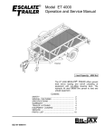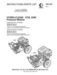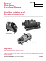
1
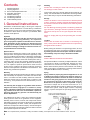
Spencer®
Multi-Stage
Centrifugal Blowers
Serial No:
Model No:
Handling, Installing and
Operating Instructions
Four-Bearing Outboard
Standard Overhung
Four-Bearing Overhung
Important
Do not operate machine in unstable, low-flow range (surge).
Read and become familiar with this manual prior to uncrating and installing your Spencer Blower equipment. This precision equipment is capable of extended service and lifespan. Realization of this potential can best be achieved through
proper handling and adherence to the instructions detailed here. Damage resulting from failure to follow correct procedures will void warranty.
The Spencer Turbine Company
Windsor, Connecticut 06095
Form AA14
Contents
I
II
III
IV
V
VI
VII
VIII
Page
General Instructions . . . . . . . . . . . . . . . . . . . . . . . . . . . 2
Coupling Alignment . . . . . . . . . . . . . . . . . . . . . . . . . . . 4
How to Order Replacement Parts . . . . . . . . . . . . . . . . 5
Lubrication Instructions . . . . . . . . . . . . . . . . . . . . . . . . 6
Standard Overhung . . . . . . . . . . . . . . . . . . . . . . . . . . . 8
Four Bearing Overhung . . . . . . . . . . . . . . . . . . . . . . . 10
Four Bearing Outboard . . . . . . . . . . . . . . . . . . . . . . . 12
Trouble Shooting Guide . . . . . . . . . . . . . . . . . . . . . . . 14
I. General Instructions
Illustrations contained here apply to three types of Spencer
Blowers. Use the illustrations or consult factory to determine
which machine you have, then read instructions paying particular attention to those which are unique to your machine. When
in doubt, consult Spencer.
Important
Read and become familiar with this manual prior to uncrating and installing or storing machinery – it is a precision
piece of equipment capable of extended service and lifespan. Realization of this potential can best be achieved
through proper handling and adherence to the following
instructions. Damage resulting from failure to follow correct procedures will void warranty.
Spencer Service
Spencer service begins upon receipt of your request for equipment purchase. Our engineers welcome the opportunity to discuss your problems and will assist in determining specification
requirements if so desired. To serve you promptly, we maintain
a large inventory of electric motors and machine parts. Also, by
combining under one roof the constantly supervised manufacturing, assembly, and test procedures, Spencer can assure you
of a unit capable of optimum performance under the most
severe service conditions. All Spencer machines are factory
tested for load capacities and vibrational characteristics. This
assures long, trouble-free operations.
Warranty
We warrant that this product will be free from defects in material
and workmanship for a period of 18 months from date of shipment or 12 months from date of startup, whichever comes first.
Within the warranty period, we shall repair or replace, F.O.B.
our Factory, such products that are determined by us to be
defective.
This warranty will not apply to any product which has been
subjected to misuse, negligence, or accident or, misapplied or improperly installed. This warranty will not apply to
any product which has been disassembled, repaired or
otherwise altered by any persons not authorized by our
Service Department.
Handling
Caution: Do not lift by the shaft end or bearing housing;
use lift rings or slots in base.
This machine has been carefully balanced and tested at our
factory. It is essential that it be handled with care during installation in order that you may be assured satisfactory performance.
Storage
Caution: If machine is to be stored for an extended period
of time, it must be carefully protected from dampness and
dirt and the shaft should be rotated a few times by hand,
every week.
On Four Bearing Overhung and/or Four Bearing Outboard
type machines, bearings must be replaced at customer
expense if start up occurs one year beyond date of shipment.
Failure to comply with any of the preceding will void warranty.
Location
Caution: Do not locate unit or controls in excessively hot
area (> 40˚C) unless the equipment has been specifically
designed for this condition.
Before placing the machine in its operating position, be sure
that the blower and motor are readily accessible for servicing
by allowing several feet of clear space around the machine.
Inaccessibility can prove costly in both time and labor.
Foundation
Caution: Blowers should not be bolted down.
No special foundation is necessary for Spencer Blowers. A level
concrete floor or block is recommended, although any other
substantial non-resonant floor will prove satisfactory. T h e
Blower base should be placed on the furnished cork isolating
pads or equivalent. Level Blower by inserting shims between
cork pads and Blower frame, if necessary.
Piping
Piping should be properly aligned and supported so as not
to produce any stress or strain on the machine casing. It is
necessary that a flexible connector be used to connect the
machine to the piping system. It is necessary that piping
be restrained to prevent its movement away from the
Blower due to air pressure when it is operated. All piping
should be of ample size to minimize frictional loss. It is
absolutely essential that all joints be airtight and that there be
no leaks in the system. Leaky air pipes consume a surprising
amount of power and impair the operating efficiency of the
system.
The guarantee of the motor, control, and component manufacturers govern the extent of our guarantee on such equipment.
Warranty work on motors, controls, and components must be
authorized by Spencer and must be performed in an authorized
shop as designated by the motor, control, and component manufacturers. The Spencer Turbine Company reserves the right to
invoice all expenses incurred when repairs are made in the field
at the specific request of the customer.
Note: For complete warranty information, including our limitation of liability, consult Spencer’s Terms and Conditions of Sale - Form 706.
2
A rubber connecting sleeve is supplied with most machines. It
should be installed so that it covers a gap of approximately one
inch as illustrated. The mounting clamps should be tightened to
effect an airtight connection.
It is important that the tubing or piping not touch or butt
the Blower; there must be a gap between the machine and
piping or tubing.
Electrical
Caution: Be sure motor, starter, controls and other electrical equipment is the proper type suitable for the application and environment and complies with all applicable
codes.
Be sure that the motor furnished with this machine is rated for
the same type of voltage available at the installation site. In
making the electrical connections, follow the wiring instructions
furnished. Wire and fuses should be of ample capacity to insure
that proper voltage is maintained at the motor terminals while
starting and running. It is important that proper starting equipment be used. All AC machines should be equipped with a
magnetic contactor or a manual or automatic compensator
depending on the machine size and the installation regulations
of the local power company. The starters should have thermal
overload protection as well as true low-voltage protection.
ened. This prevents motor overload. The blast gate may then
be used for throttling purposes. Current readings at motor must
be compared with readings on ammeters (when furnished) to
be sure they are the same. If readings are not the same, contact Spencer’s Service Department.
Periodic Operation
Caution: All Blowers should be operated periodically. This
can be accomplished through bi-weekly alternate operation
of the machines.
Parallel Operation
Caution: Check valves must be installed in the discharge of
each Blower connected in parallel to prevent blow-back
through the unit not in operation. When operating two or
more Blowers in parallel it is necessary to be sure that
each machine carries its respective share of the load.
After accomplishing start-up of each machine, proceed as follows. Check the current reading at each motor to be sure they
are the same. If current readings are approximately the same it
indicates blowers are sharing equal system load. It may be nec essary to re-adjust the control device to attain similar readings
on the ammeters.
In most cases low flow protection for the equipment is
required.
Start-Up
Coupling-equipped Machines
Caution: Before start-up, the coupling must be aligned in
accordance with the information contained in Section II,
Coupling Alignment, or with the manufacturer’s instructions accompanying each coupling.
The following procedures apply to start-up of all Spencer
Blowers.
Caution: The Blower must be electrically wired with regard
to the correct direction of rotation. A direction-of-rotation
arrow is affixed to the blower casing. To check rotation
direction depress start button, immediately depress stop
button and observe that the motor drive shaft rotation coincides with the arrow attached to the casing. Available dis charge positions (viewed from intake end) and the correct
relationship of the discharge position to rotation are shown
in the following diagram.
Caution: Operation of Positive Displacement Blowers in
parallel with Centrifugal Blowers is not recommended and
may result in damage to the Centrifugal Blower.
Under no circumstances should the Blower be operated
without being connected to the pipe system with which it is
used or motor overload will occur.
When starting up a Blower it is recommended that a blast
gate or other control device be closed. When first starting
the Blower, an ammeter should be connected to the motor circuit and the control device opened until full load current is
reached. At this point, the blast gate locking nut should be tight-
Surge (Unstable Low Flow)
Caution: Do not operate the Blower below the minimum
safe operating flow. Operation below the minimum flow will
result in surge or in excessive discharge temperatures.
Damage to the Blower because of operating below minimum safe flow will not be covered by Spencer
warranty.
A unit in surge can produce a breathing or pulsating discharge noise. It may also be detected by movement on an
ammeter scale or manometer. Increasing the volume flow
sufficiently should eliminate this condition. This may be
accomplished by bleeding air or recirculating the gas.
3
II. Coupling Alignment
Caution: The coupling on this machine was carefully
aligned at the factory and the coupling halves and shell(s)
marked to indicate optimum relative position. However,
transportation may have caused coupling misalignment. It
is essential, therefore, that the motor and blower shafts be
checked for misalignment and carefully realigned if necessary after installation and before start-up, as misalignment
can cause destructive vibration.
Reverse Indicator Method (Preferred)
1. Reinstall the coupling sleeve, seal and snap ring.
2. Clamp dial indicators on shafts, 180 degrees apart.
3. Place indicator probes on opposite shafts as shown.
4. Rotate both shafts simultaneously in the correct operating
direction, taking readings at 90 degree intervals.
5. Adjust motor to achieve parallel and angular alignments.
If questions arise, contact the Spencer Service Dept.
Coupling alignment should be rechecked again after an
hour’s operation. Final alignment should be made at average operating temperature. After each alignment check,
add lubricant per instructions and replace coupling guard.
On certain Blowers, the coupling is disassembled after factory
alignment and marking. The coupling halves are specially protected against the elements and the machine is shipped. Prior
to start-up, it is necessary on these machines to assemble,
align key ways using factory markings, and lubricate in accordance with the instructions supplied with the machine and contained here.
Coupling alignment provides for aligning, in the horizontal and
vertical planes, the motor shaft with the Blower shaft, and insuring adequate clearance (gap) between the two coupling halves.
Only qualified maintenance personnel should attempt to align a
coupling. If doubt exists as to competency or if problems arise
contact The Spencer Turbine Company.
Sier Bath Coupling (See accompanying illustrations)
Sier Bath gear type couplings are the most common coupling
supplied with Spencer equipment. These are manufactured to
our rigid specifications.
Sier Bath
Coupling Size
7/8
1 1/2
2
2 1/2
3
3 1/2
4
4 1/2
5
6
7
9
11
12
Dimension “C” (hub to hub)
Gap
1/8
1/8
1/8
1/4
1/4
1/4
1/4
1/4
1/4
1/4
3/8
1/2
1/2
1/2
Remove one snap ring and slide the sleeve off the hub halves.
Using a feeler gauge, verify that the gap between coupling
halves, is in accordance with the chart above.
Caution: Be careful because some motor shafts are spring
loaded axially. When using a feeler gauge take care not to
compress the shaft and disturb the normal at-rest position.
To align this coupling, Spencer recommends one of the following procedures.
4
Straight Edge Method (Permissible)
1. Remove the old lubricant and clean the hub teeth.
2. Set a machine shop quality straight edge across the coupling
hubs (at the root diameter of the gear teeth).
3. Adjust the motor so the straight edge is evenly supported
between the coupling hubs at the 3, 6, 9, and 12 o’clock
positions.
4. Using a feeler gauge, measure the clearance between the
coupling hubs at the 3, 6, 9, and 12 o’clock positions.
5. Adjust the motor so that the gap is identical at the 3, 6, 9,
and 12 o'clock positions and in accordance with the
dimension “C”.
Caution: Be sure to relubricate coupling after alignment
and before operation.
Coupling Alignment with Sleeve Bearing Motors
Caution: Where sleeve bearing motors are used, it is necessary to complete the following procedures before coupling alignment is attempted.
Unless otherwise specified by the customer, a flange type gear
coupling should be used for both 1800 and 3600 RPM applications. Do not use a sleeve type coupling.
Sleeve bearing motors have a specified end play. End play limits and the magnetic center (where motor will run) should be
scribed on the shaft by the manufacturer.
When aligning a sleeve bearing motor with a machine, use the
following procedure:
1. The motor shaft must be level.
2. Position the motor so that when the rotor is pushed toward
the machine as far as it will go, there will be 0.030 clearance
between the ends of the machine and motor shafts (or the
alignment faces on the coupling hubs).
3 . Proceed with the coupling alignment in accordance with
applicable instructions.
III. Replacement Parts
How to order replacement parts
When ordering replacement parts, it is important that the information you furnish to Spencer is correct and complete. Be sure
when reading nameplates that you obtain the correct information. Record nameplate information on one of the typical nameplates shown here and on the cover to use as a reference when
ordering parts. Remember, the more complete the information,
the quicker the order will be processed; incomplete information
will result in unnecessary delays and expense through callbacks. When in doubt, consult the factory for further information.
To order replacement parts, furnish the following:
1. Record machine serial number and catalog/model number
from machine nameplate.
2. Record motor horsepower from motor nameplate.
3. Measure and record the casing diameter.
4. Refer to applicable illustration in the instruction manual and
locate needed item by its circled call-out number. Refer to
call-out list for nomenclature and record.
5. When ordering impellers and deflectors be sure to include
the letter designation shown on the applicable illustration. An
alternate method would be to count the number of fans from
the end of the casing.
6. Include the form number from which you have extracted the
nomenclature. The form number is shown in the bottom right
corner of the cover page and will read AA, EE, etc.
The following are recommended spare parts:
Standard Overhung (refer to drawing for item numbers).
Item Number
1
2
4
8
9
12
15
19
Nomenclature
Motor
Division head packing
Rope packing
Impellers
Interstage packing
End head gasket
Drive End motor bearing
Opposite Drive End motor bearing
Four Bearing Overhung (refer to drawing for item numbers).
Item Number
1
5
5A
6
6A
10
14
16
18
21
23
Nomenclature
Flexible coupling
Coupling End bearing
Blower End bearing
Division head packing
Division head packing plate
Impellers
Interstage deflector packing
End head gasket
Rope packing
Drive End motor bearing
Opposite Drive End motor bearing
Four Bearing Outboard (refer to drawing for item numbers).
Item Number
2
3
10
18
18A
20
22
25
29
32
34
37
38 or 39
Nomenclature
Drive End motor bearing
Flexible coupling
Rope packing
Thrust washer
Outboard bearing(s)
End head packing
End head gasket
Interstage deflector packing
Impellers
Division head packing
Inboard bearing
Opposite Drive End motor bearing
Metallic packing (if machine equipped with
packing box).
5
IV. Lubrication
Instructions
Caution: Recommended blower bearing grease is Chevron
SRI, Number 2. Use of any other grease will void warranty.
General
Proper lubrication procedure is important to Blower maintenance. These instructions should be closely followed to assure
trouble-free operation of the equipment.
Standard Overhung Lubrication
Spencer’s Standard Overhung Blowers do not require lubrication except for motor bearing lubrications required by the motor
m a n u f a c t u r e r. See paragraph entitled Motor Bearing
Lubrication.
Four Bearing Overhung and Four Bearing Outboard
Bearing Lubrication
Spencer Four Bearing Overhung and Outboard Blowers are
equipped with deep-groove radial ball bearings designed to
carry the thrust and radial loads. These bearings are packed
with the proper amount and grade of lubricant before the unit is
shipped from the factory. For this reason, lubrication prior to
first operation is not recommended and should not be
attempted.
Bearing Lubrication Procedure and Frequency Guide
Lubrication is required based on operating frequency and
conditions. Many bearing failures are caused by excess
grease which results in over-heating and consequent
bearing failure.
The Blower bearings, as lubricated at the factory, carry an adequate amount of proper grade of grease for 1500 to 8000 hours
of continuous operation prior to lubrication, depending upon
atmospheric conditions and size. An average lubrication interval
therefore should be established based on existing conditions.
Several factors contribute to frequency of lubrication:
1. Operating temperatures (bearing)
2. Indoor or outdoor operation
3. Dusty or clean atmosphere
4. Ambient temperature
5. Predicted duty cycle
6. Bearing size and speed
Assuming an ideal 8000 hour lubrication interval, reduce the
time factor by applying the preceding conditions as follows:
Operating Condition
I.
*Lubrication Interval
Blower Bearings
1. 120˚F to 155˚F bearing
temperature
2. Indoor installation
3. Clean atmosphere
4. 40˚F to 100˚F ambient
temperature
5. Continuous operation
4000-6000 average
operating hours
II.
Same conditions as “I”,
above except:
Intermittent operation
6000-8000 average
operating hours
III.
1. 120˚F to 155˚F bearing
temperature
2. Outdoor installation
3. All atmosphere
conditions
4. 0˚F to +104˚F ambient
temperature
5. Continuous operation
3000-5000 average
operating hours
IV.
Same conditions as “III”,
above except:
Intermittent operation
5000-7000 average
operating hours
*Note: Higher limits apply to smaller bearings (#308 and smaller). Lower limits apply to large bearings.
An extremely dirty atmosphere, in addition to the above factors,
could decrease the lubrication period as much as 50%. The
above chart serves only as a guide.
To lubricate blower bearings, proceed as follows:
1. Shut down machine.
2. Remove guards as necessary.
3. Inject the recommended grease (Chevron SRI No. 2) using a
grease gun. The amount of grease will vary with bearing size.
4. Reinstall guards and restart the Blower.
Caution: Do not run Blower unless guards are properly
installed.
Recommended Bearing Lubricant Type
The bearings of Four Bearing Outboard and Four Bearing
Overhung Turbo Blowers are packed at the factory with
Chevron SRI, Number 2 grease. The general specifications are:
Grade or consistency . . . . . . . . . . . . . . . . . . . . . . . . . . . . . . .#2
Thickener . . . . . . . . . . . . . . . . . . . . . . . . . . . . . . . . . . .polyurea
ASTM Dropping Point . . . . . . . . . . . . . . . . . . . . . . . . . . . .480˚F
Work Penetration . . . . . . . . . . . . . . . . . . . . . . . . . . . . . . . . .270
Base Oil Viscosity . . . . . . . . . . . . . . . . . . . . .600 SUS @ 100˚F
Color . . . . . . . . . . . . . . . . . . . . . . . . . . . . . . . . . . . .Blue-Green
Chevron SRI, Number 2 is available from Spencer.
6
Note: The intermixing of incompatible greases will result in
loss of lubrication and bearing failure which is NOT covered under the Spencer warranty.
Lubrication of Replacement Bearings (Four bearing designs
only) When installing new bearings, it is necessary to repack
bearings with grease. Do this by forcing grease into the bearings and “butter” both sides with grease so that the grease is
flush with the race. Use only Chevron SRI #2 grease. For outboard tandem bearing installation, follow procedures packed
with each new bearing set. Remember, these bearings are
manufactured as a set to Spencer’s rigid specifications.
Motor Bearing Lubrication (Applicable to all)
Follow motor manufacturer’s recommendations. Some motors
equipped with sealed bearings are not intended to be re-lubricated. There are, therefore, no grease or drain plugs on motors
of this type.
Flexible Coupling Lubrication
Gear type couplings must contain lubricant at all times.
Re-lubricate after checking alignment. Follow the coupling manufacturer’s recommendations.
Lubricated couplings on machines shipped from Spencer have
been serviced with Texaco Marfax #1 grease. All couplings
should be re-lubricated prior to start-up.
To re-lubricate Sier Bath without disassembling coupling,
remove both lube plugs and position lube holes at 45˚ to horizontal. Force grease into top hole until clean grease flows out
of opposite lower holes. Reinstall both plugs and wipe off all
excess grease. Re-lubricate every six (6) months.
Coupling Half Removal
Gear type couplings generally require the application of heat
and the use of a puller to remove.
7
V. Standard Overhung
Machine
Instructions for Disassembly and Reassembly (Multi-Stage)
Warning: Be sure all electrical power is disconnected prior
to performing Blower maintenance.
Caution: Parts must be reassembled in exactly the same
relative positions. Therefore, it is recommended that each
part be marked as it is removed from the machine to facilitate later reassembly. It is especially important that the
location of each impeller, as well as its position on the
shaft, be marked.
When ordering replacement impellers and deflectors, refer
to the Notes on accompanying illustration.
General Configuration
The most common Spencer machines (standard overhung type
construction) have the impellers mounted directly on the
extended motor shaft and are available as either single-stage or
multi-stage units. The multi-stage units are provided with deflectors to channel the air efficiently from one impeller to the next.
The single-stage units are equipped with one impeller mounted
between the end head and division head of the machine housing. The motor bearings support the shaft and impeller assembly. Besides the customary motor maintenance, no additional
attention is required by the unit.
Disassembly
1. Remove End Head Bolts (5) and End Head (6).
2. Mark the motor shaft and impeller (8) hub with an arbitrary 12
o’clock reference point. Remove the first stage impeller (8A)
and mark it for reference during reassembly.
3. Check axial position of each deflector (7) at four radial points
with reference to end of casing and record for reference
when reassembling unit.
4. Remove spacer (14A) holding rope packing (4) in place.
Mark spacer for reference during reassembly.
5. Remove rope packing (4) holding deflector in place. Remove
deflector (7A). Mark for reference during reassembly.
6. Proceed to remove remaining stages in the same way, marking each component to insure proper reassembly.
Note: Division Head (3) cannot be removed.
7. Unbolt division head packing plate (2A) and slide packing
plate and packing (2) back on the shaft.
8. Remove motor mounting bolts and slide motor (1) back.
Reassembly
1. Place the division head packing plate (2A) and packing (2)
on the shaft. If for any reason the packing (2) is damaged,
replace it. Install the motor (1) in the casing in its
original position. Be sure that the shaft is centered in the
casing. Assemble the packing (2) and packing plate (2A) to
the division head.
2. Run the motor (1) to check for vibration. If excessive vibration is present, check the shaft for runout.
3. Place the first impeller (8C) on the shaft up against the
division head (3). Mark the shaft approximately 1/8” out and
withdraw the impeller to this point. This will insure a clearance of 1/8” behind the impeller. Tighten the hub securely.
4. Inspect the interstage packing (9), if applicable, on deflector
(7B) and replace if damaged.
8
5. Place deflector (7B) back tightly against the stops in the
casing. Install the rope packing (4) firmly into the groove,
using a suitable tool.
6. Install the next impeller (8B) on the shaft up against the
deflector (7B). Mark the shaft approximately 1/8” out and
withdraw the impeller to this point. Tighten the hub securely.
7. Install the spacer (14B) into the casing. Make sure spacer
and deflector (7B) are pressed back tightly and at a uniform
distance from the end of the casing at four points.
8. Proceed in a like manner with remaining impellers, spacers
and deflectors.
9. Reassemble the end head (6) to the casing using a new
endhead gasket (12).
Balancing
Each machine is fully tested before leaving the Spencer factory
to be sure vibrations, if any, are well within specifications for this
particular machine. However, rough handling during shipment
or improper disassembly/reassembly of a machine can upset its
balance and/or result in excess vibration.
If there is any vibration due to an unbalanced condition after
assembly, use the following procedure.
After running at operating speed and when at rest, mark position of end impeller hub on shaft. Loosen bolts or screws holding impeller on shaft. Rotate impeller 90˚ on shaft. Retighten
bolts or screws. Run machine again at operating speed and
check vibration. Repeat this process until the best position is
located for the impeller on the shaft so that there is no vibration
in the machine.
N o t e : In the event of trouble, notify The Spencer Tu r b i n e
Company, Windsor, Connecticut, or the nearest Spencer representative, describing in detail the nature of the difficulty before
attempting to disassemble the machine.
Typical Multi-Stage Standard Overhung Type (SOH)
Discharge
Intake
Notes:
1. Although three impellers and two deflectors are shown in this
typical drawing, the number, in each machine, will vary depen dent on the specific machine’s design criteria. To determine the
number of impellers and deflectors in a specific machine, con sult the factory. Be sure to include machine serial number and
appropriate impeller/deflector letter designation.
2. When ordering replacement parts, refer to Section III.
Screened items are recommended spare parts
1 - Motor and Shaft Assembly
2 - Division Head Packing
2A - Division Head Packing Plate
3 - Division Head (Not available as separate item)
* 4 - Rope Packing for Deflector
5 - End Head Bolts
6 - End Head
7 - Deflector (A,B, Etc.)
8 - Impellers (A,B, Etc.)
9 - Inter-Stage Deflector Packing
9A- Center Deflector Plates (normally not furnished on 30"
or smaller machines)
10 - Split Clamped Hub or Tapered Bushing Clamp
(Part of Impeller Assembly)
12 - End Head Gasket
13 - Feet
14 - Spacers
15 - Drive End Motor Bearing
16 - Casing
17 - Motor Base
18 - Motor Hold-Down Bolts
19 - Opposite Drive Motor Bearing
* Felt on Multi-stage Adjustable Discharge Type
9
VI. Four-Bearing
Overhung Machine
Instructions for Disassembly and Reassembly
Warning: Be sure all electrical power is disconnected prior
to performing Blower maintenance.
Caution: Parts must be reassembled in exactly the same
relative position. Therefore, it is recommended that each
part be tagged as it is removed from the machine to facilitate later reassembly. It is especially important that the
location of each impeller, as well as its position on the
shaft, be marked.
When ordering replacement impellers and deflectors, refer
to notes on accompanying illustrations.
General Configuration
The four bearing unit employs the overhung impeller construction with the rotating element supported by a rigid ball bearing
bracket and shaft. The equipment is driven through a flexible
coupling.
Disassembly
1. Remove End Head Bolts (8) and End Head (11).
2. On other than keyed construction, mark the shaft (13) and
impeller (10) hub with an arbitrary 12 o’clock reference
point. Remove the first stage impeller (10A) and mark it for
reference during reassembly. On keyed construction,
remove snap ring. Remove impeller (10A) and its hub
spacer and any shims, marking them for replacement in
their proper position.
3. Check axial position of each deflector (9) at four radial
points with reference to end of casing and record for
reference when reassembling unit.
4. Remove spacer (15) holding rope packing (18) in place.
Mark spacer for reference during reassembly.
5. Remove rope packing (18) holding deflector in place.
Remove deflector (9). Mark for reference during
reassembly.
6. Proceed to remove remaining stages in the same way,
marking each component to insure proper reassembly.
Note: Division Head (4) cannot be removed.
7. Rotate the Blower shaft (13) so that the keyway is in the
12 o’clock position. Mark the motor shaft and coupling hub
to show the corresponding 12 o’clock position. Remove
snap ring on blower side of coupling (1) and slide coupling
sleeve back.
8. Remove motor mounting bolts and slide motor (23) back.
Identify and secure individual motor shim packs under each
motor foot for reassembly.
9. Unbolt division head packing plate (6A) and slide packing
plate and packing (6) back on the shaft.
10. Mark the Blower end and coupling ends of the bracket (7)
for reference. Remove bearing bracket hold down bolts and
slide bracket/shaft assembly out of the casing.
11. Using heat and a puller, remove the coupling hub from the
shaft.
12. Unbolt the bearing caps and remove. These caps are NOT
identical so label the coupling end and blower end caps
c l e a r l y. Remove the bearings (5 & 5A) from the shaft.
Remove the shaft from the bracket.
10
Reassembly
1. Assemble the shaft (13) in the bracket with new bearings
(5 & 5A) and grease. Assemble the caps, being careful to
insure the correct cap on each end.
2. Using heat, assemble the coupling hub on the shaft (13).
3. Place the division head packing plate (6A) and packing (6)
on the shaft. If for any reason the packing (6) is damaged,
replace it. Install the bracket/shaft assembly into the casing
in its original position. Be sure that the shaft is centered in
the casing. Assemble the packing (6) and packing plate
(6A) to the division head.
4. Move the motor (23) back into its original position. Insure
an adequate gap between the coupling hubs. Align the
motor (23) to the blower shaft (13) following the instructions
on page 4 of this manual.
5. Rotate the Blower shaft to the 12 o’clock position and align
the corresponding mark on the motor coupling hub.
Recouple the motor (23) to the shaft (13) and run the
assembly to check for vibration. If excessive vibration is
present, check the shaft (13) for runout.
6. On keyed construction, the impellers (10), spacers and
shims are reassembled in precise reverse order of their
disassembly. Verify clearance at each stage. On other than
keyed construction, place the first impeller (10C) on the
shaft up against the division head (4). Mark the shaft (13)
approximately 1/8” behind the impeller and withdraw the
impeller to this point. This will insure a clearance of 1/8”
behind the impeller. Tighten the hub securely.
7. Inspect the interstage packing (14A), if applicable, on
deflector (9B) and replace if damaged.
8. Place deflector (9B) back tightly against the stops in the
casing. Install the rope packing (18) firmly into the groove,
using a suitable tool.
9. Install the next impeller (10B) on the shaft up against the
deflector (9B). Mark the shaft approximately 1/8” out and
withdraw the impeller to this point. Tighten the hub securely.
10. Install the spacer (15) into the casing. Make sure spacer
and deflector (9B) are pressed back tightly and at a uniform
distance from the end of the casing at four points.
11. Proceed in a like manner with remaining impellers, spacers
and deflectors.
12. Reassemble the end head (11) to the casing using a new
end head gasket (16).
Balancing
Each machine is fully tested before leaving the Spencer factory
to be sure vibrations, if any, are well within specifications for
that particular machine. However, rough handling during shipment or improper disassembly/reassembly of a machine can
upset its balance and/or result in excess vibration.
If there is any excessive vibration due to an unbalanced condition after assembly, use the following procedure:
1. Check coupling for misalignment. If realignment does not
correct the vibration, rotate coupling hubs or machine shaft
and motor shaft 90˚ in continuous increments.
2. If vibration persists, shut the Blower down. Mark the position
of end impeller hub on the shaft. Loosen bolts or screws
securing the impeller. Rotate impeller 90˚ on shaft.
Retighten impeller. Run machine again at operating speed,
and check for vibration. Repeat this process until the best
position is located for impeller on shaft so that there is no
vibration in the machine.
Note: In case of trouble notify The Spencer Turbine Company,
Windsor, Connecticut, or the nearest Spencer representative,
describing in detail the nature of the difficulty before attempting
to disassemble the machine.
Typical Four-Bearing Overhung Type (4BOH)
Discharge
Intake
Notes:
1. Although three impellers and two deflectors are shown in this
typical drawing, the number, in each machine, will vary depen dent on the specific machine’s design. To determine the num ber of impellers and deflectors in a specific machine, consult
the factory. Be sure to include machine serial number and
appropriate impeller/deflector letter designation.
2. The impellers are equipped with a split clamped hub as
illustrated or tapered bushing hubs. The latter is tightened
on the shaft with Allen socket screws.
3. When ordering replacement parts, refer to Section III.
Screened items are recommended spare parts
1
2
3
- Flexible Coupling
- Coupling Guard
- Bearing Bracket Lubrication
Fitting
* 4 - Division Head
5 - Coupling End Bearing
5A - Blower End Bearing
6 - Division Head Packing
6A - Division Head Packing Plate
7 - Bearing Bracket
8 - End Head Bolts
9 - Deflectors (A,B,Etc.)
10
11
12
13
14
14A
15
16
17
- Impellers (A,B,C, Etc.)
- End Head Assembly
- Impeller Bolts (or Screws)
- Shaft
- Inter-stage Deflector Packing
- Center Deflector Plates (Normally not
furnished on 30" or smaller machines)
- Spacers
- End Head Gasket
- Feet
18
19
20
21
22
23
- Rope Packing for Deflector
- Casing
- Base for Bearing and Motor
- Drive End Motor Bearing
- Motor
- Opposite Drive End Motor
Bearing
* Not available as a separate item
11
VII. Four-Bearing
Outboard Machine
Instructions for Disassembly and Reassembly
Warning: Be sure all electrical power is disconnected prior
to performing Blower maintenance.
Caution: Parts must be reassembled in exactly the same
relative positions. Therefore, it is recommended that each
part be marked as it is removed from the machine to facilitate later reassembly. It is especially important that the
location of each impeller, as well as its position on the
shaft, be marked.
When ordering replacement impellers and deflectors,
refer to Notes on accompanying illustrations.
General Configuration
In four-bearing units of the outboard type, the impellers are
mounted between two supporting bearings of the Blower. The
equipment is driven by means of a flexible coupling, and
although most standard makes of couplings can be used, a
gear type is normally furnished unless otherwise specified.
Standard sleeve bearing or ball bearing motors with standard
shaft dimensions are included, and the entire assembly is typically mounted as shown.
Caution: Most four-bearing outboard machines have a
duplex (tandem) bearing assembly. These bearings are
available only from Spencer as a custom-matched set of
two: one bearing for thrust and one bearing for radial load.
These bearings are not interchangeable with commercially
available bearings carrying the same part number; they
can only be used in matched sets as furnished by The
Spencer Turbine Company. For best results, follow instructions enclosed with each matched set of bearings.
Disassembly & Reassembly
1. Remove packing plate nuts from packing plate (32 and 20)
on each end of machine. Slide both packing plates and packing (32 and 20) on shaft away from heads. Remove all packing from packing box when applicable (38 & 39).
2. Remove snap ring and back off coupling sleeve. Check gap
between coupling hubs. See coupling manufacturers instructions for other than Sier Bath.
3. Measure distance “B” from outboard bearing bracket (19) to
outboard bearing cap (17). Remove bolts in thrust assembly
housing cap.
4. Remove lock nut (15) and washer from end of shaft, and
loosen bolt (21) binding housing in bracket.
5. Remove bracket bolts (19A). Using puller, remove complete
thrust assembly and bearings.
6. Remove bolts on end head, holding flat ring and end head to
casing. (Use a chain hoist if available to hold head while
removing bolts). After removal of end head, keep shaft
supported while removing internal parts.
7. Remove intake spiral (13) after marking position to insure
correct reassembly. See note (A).
8. Remove rope packing (10) and half deflector (26).
9. On other than keyed construction measure distance from
impeller hub to any step or shoulder on shaft, and mark for
reassembly. On stacked and keyed construction, remove
nuts and washers (24A) and shaft sleeves (24B). Remove
impeller (29) and its hub spacer, number or mark them for
replacement in their proper position. See note (B) following
paragraphs.
12
10. Check axial position of each deflector at 4 radial points with
reference to end of casing and record.
11. Remove spacer (27) holding rope packing in place. Number
or mark for replacement.
12. Remove rope packing holding deflector in place. Then pull
or work deflector (11) out of casing. Number or mark for
replacement.
13. Proceed to remove the remaining stages in the same way,
numbering or marking all impellers, spacers, deflectors,
etc., to insure proper replacement.
14. Check deflector stops for damage.
15. Reassemble in reverse order, replacing end head gasket
(22) and any worn packing (32, 10, 25, 20).
To Change the Inboard Bearing (Motor End of the Machine)
1. Remove snap ring and back off coupling sleeve.
2. Check gap on coupling hubs.
3. Loosen and remove motor bolts, and slide motor back.
4. Remove coupling hub from machine shaft.
5. Remove packing plate nuts from packing plate (32 and 20)
on each end of machine. Slide both the packing plates and
packing (32 and 20) on the shaft away from the heads.
Remove all packing from packing box where applicable.
6. Remove bolts on both caps (8 and 8A) on three-arm
bearing bracket (33).
7. Slide front cap off shaft, and push back cap away from
bracket.
8. Remove bolts holding inboard bracket in position while
supporting end of shaft.
9. Slide inboard bracket off bearing.
10. Remove locknut, washers, and bearing.
11. Replace bearing and parts in their proper order.
Realign coupling and check the hub before and after bolting
motor in place (Refer to page 4).
Notes:
(A) Upon reassembly, with all internal parts installed, the intake
spiral edge should project slightly beyond end of casing so that
end head will hold all stationary parts in position.
(B) On stacked and keyed impeller construction, the first nut
installed is tightened with a spanner wrench, then loosened one
full turn to allow for impeller hub expansion. The second nut is
brought up to the first nut with the lockwasher in between. Lock
nut in position with washer tabs.
Balancing
Each machine is fully tested before leaving the Spencer factory
to be sure vibration, if any, is within specifications for the particular machine. However, rough handling during shipment or
improper disassembly/reassembly of a machine can upset its
balance and result in excess vibrations.
When a machine is being disassembled for repairs, mark the
parts as they are removed. If this is done, no trouble should be
expected from vibration when they are re-assembled in the
same order.
However, if the impellers are being replaced or there is any
vibration due to an unbalanced condition after assembly, use
the following procedure:
If there is any vibration or unbalance, the coupling should be
checked first for misalignment. If realignment does not correct
imbalance, rotate coupling hubs or machine shaft and motor
shaft in 90˚ increments until minimal vibration is obtained.
Typical Four-Bearing Outboard Type (4BOB)
Intake
Discharge
Notes:
1. Although eight impellers and seven deflectors are shown in
this typical drawing, the number in each machine will vary
dependent on the specific machine’s design criteria. To deter mine the number of impellers and deflectors in a specific
machine, consult the factory. Be sure to include machine serial
number and appropriate impeller/deflector letter designation.
2. The impellers are equipped with keyed hubs as illustrated
or split clamped hubs shown below.
3. When ordering replacement parts, refer to Section XIV.
Screened items are recommended spare parts
1
2
3
4
6
- Motor
- Drive End Motor Bearing
- Flexible Coupling
- Coupling Guard
- Inboard Bearing Lubrication
Fitting
- Division Head
*7
8
- Inboard Bearing Cap Front
8A - Inboard Bearing Cap Rear
9
- Heat Fan Guard
10 - Rope Packing for Deflectors
11 - Deflectors (A,B,C, Etc.)
12 - End Head Bolts
13 - Intake Spiral
13A - Grease Drain
14 - End Head Assembly
Alternate internal construction of a four
bearing outboard Blower with split
clamped hubs
15
16
17
17A
18
18A
19
19A
20
20A
21
22
23
24
24A
- Outboard Bearing Nut and Washer
- Outboard Bearing Lubrication Fitting
- Outboard Bearing Cap
- Outboard Bearing Housing
- Thrust Washer (where applicable)
- Outboard Bearing(s)
- Outboard Bearing Bracket
- Housing Locking Bolt and Nut
- End Head Packing (where applicable)
- End Head Packing Plate
- Bracket Bolts
- End Head Gasket
- Casing
- Shaft and Keys
- Impeller Assembly Lock Nuts (2) and
Washer (1)
24B - Shaft Sleeves (Two; one keyed)
Packing box used on Gas Boosters.
See Form DD
25
25A
26
27
28
29
31
32
32A
33
34
35
- Inter-Stage Deflector Packing
- Center Deflector Plates
- Half Deflector
- Spacers
- Feet
- Impellers (A,B, C, Etc.)
- Heat Fan
- Division Head Packing
- Division Head Packing Plate
- Inboard Bearing Bracket
- Inboard Bearing
- Inboard Shaft Locking Nut
and Washer
36
- Common Base
37
- Opposite Drive End Motor
Bearing
38,39 - Metallic Packing
* Not available as a separate item
Packing box used where pressure exceeds
7.5 psi and for other special applications.
13
VIII. Trouble Shooting Guide
Trouble
Probable Cause
Insufficient air or gas
through system
Low pressure or vacuum as determined by measurement with a manometer:
– Incorrect rotation.
– Customer has reassembled machine incorrectly.
– Machine sized for requirements given, but air or gas lines
too small causing excessive frictional loss.
– Valves in line, causing excessive losses.
– Inlet or outlet partially blocked, i.e., clogged inlet filter,
blast gate shaft slipped in handle and shutter does not
open fully.
– High inlet temperature, i.e., higher than designed inlet
temperature.
– Lower inlet pressure, i.e., lower than designed inlet
pressure.
– Machine not running at designed speed.
– Lower than design gas density or specific gravity.
– Machine air passages clogged with material.
– Impellers worn out due to explosion, abrasion, or vibration.
– Inlet spiral has rotated partially blocking inlet (4-bearing
outboard machines only).
Corrective Action
Change motor leads to correct rotation.
Refer to instructions in this book and to assembly print;
disassemble machine and reassemble properly.
Increase line sizes or install machine providing higher
output pressure.
Install larger valves or install machine providing higher
output pressure.
Check blast gate; remove and repair if necessary.
Direct inlet line to cooler area; replace machine with
one designed for correct temperature.
Remove inlet restrictions or install machine providing
higher output pressure.
Refer to motor manufacturer’s instructions; check
motor speed; check voltage connections.
Check gas analysis; increase density or install
machine designed for correct requirements.
Disassemble, clean and inspect all parts.
Replace Impellers.
Rotate spiral to correct position and pin or clamp in
position.
Machine design capacity too small for the system:
– System requirements incorrectly calculated by customer.
– Too many leaks and/or openings.
Install larger volume or lower pressure machine to
handle correct system requirements.
Locate and repair all leaks.
Measuring gas or air flow incorrectly:
– Flowmeters incorrectly calibrated.
– No means of measurement available so customer is
guessing at airflow.
Machine noisy
Calibrate flowmeters; be certain proper orifice is used
for meter (check with flowmeter manufacturer).
Obtain and install flowmeter.
External machine malfunction – bearing whining or growling:
– Too much grease – bearing hot.
– Too little grease – bearings dry.
– Bearing(s) failure.
– Bearing retainers worn.
– Bearings turning on shaft – retaining nut loose.
– Bearing turning in housing – housing worn.
– Bearings replaced incorrectly – particularly in tandem
assembly, i.e., angled, cramped or put in backwards.
– Bearing(s) overloaded – too much thrust due to higher
density gas or air than designed for.
Remove excess grease. Check bearing temperature
(refer to lubrication instructions in this manual).
Grease according to instructions.
Replace bearing(s).
Replace bearing(s).
Tighten nut, check for damage.
Replace housing and bearing.
Install bearings correctly according to instructions:
check bearing, shaft and housing dimensions.
Replace bearing(s). Reduce thrust by lowering gas or air
density, installing smaller Impellers, or installing
machine designed to proper conditions.
Internal machine malfunction:
– Impeller(s) hitting after customer reassembly and/or
Impeller(s) slipping shaft due to heat or excessive inlet
pressure.
– Impeller(s) coming apart due to age or wear from dirty air
or gas.
– Deflector coming apart due to age or wear from dirty air
or gas.
– Machine operating in surge or unbalanced flow range.
– Keyed hubs rattle on start up.
– Machine out of balance, running rough.
– Deflector packings rubbing on shaft or Impeller hub
(will seat themselves if new).
– Motor not aligned in casing (Standard Overhung) causing
Impeller to hit.
– Four-bearing machines – coupling misaligned and/or dry
of grease.
– Foreign material in machine.
14
Reassemble according to instructions, tighten
Impellers. Bleed air at low flow to reduce heat. Change
inlet conditions if necessary.
Replace Impeller(s).
Repair or replace deflector.
Increase air flow to stop surge condition.
Normal. These will be loose when machine is cold –
they will tighten as machine reaches operating
temperature.
Rebalance and/or clean machine (See next problem –
“Machine Vibrating”).
Ignore if audible only when machine turned by hand.
If otherwise audible, replace packings.
Reassemble and carefully align shaft and motor properly.
Check alignment; check coupling for wear and replace if
necessary. Relubricate according to instructions.
Disassemble machine, inspect and clean. Reassemble
and, if necessary, install filter to prevent further clogging.
Trouble
Probable Cause
Corrective Action
Motor malfunctions:
– Electric hum or whine – some usually normal.
– Wrong voltage – low voltage motor not up to speed. High
voltage will burn out motor and also cause noticeably
more noise.
– Bearing (see above)
– Motor rebuilt improperly – thrust taken on wrong end in
standard overhung machine.
– Loose part in motor.
– Low frequency.
Machine vibrating
Check motor manufacturer’s instructions. Check voltage
supply and connections.
Check for proper voltage at motor and correct.
Rebuild motor properly and correct end play.
Tighten, repair or replace (check with motor
manufacturer)
Separate power supply; correct frequency.
Imbalance:
– Material build-up on Impeller(s).
– Shaft bent – possibly in shipment – (.001 maximum shaft
run per 10" of length for standard and 4-bearing overhung
machines).
– Bearing(s) failure.
– Faulty replacement motor installed and /or machine
reassembled incorrectly.
– Impeller(s) failure.
Clean Impeller(s); install filter to prevent further build-up.
Replace shaft.
Replace bearing(s).
Disassemble machine, balance motor, reassemble
according to instructions in this book and assembly print.
Replace Impeller(s).
Mechanical:
– Motor not aligned in casing (standard overhung &
4-bearing overhung), Impeller rubbing.
– Coupling misaligned (4-bearing machines).
– Inlet and/or outlet piping connected to machine without
flexible connector causing torque or strain on casing.
– Machine bolted down causing change in alignment.
– Bearing(s) cramped due to improper fit.
– Piping not properly supported.
– Improper voltage on motor causing assembly to operate
at different speed.
– Packing box(es) too tight, too loose, wrong packing,
packing dried out and/or worn out, out of alignment.
Mechanical seals misaligned, broken or worn out.
– Solids or liquids in, or passing through machine.
– Machine operating in surge or unbalanced flow range.
– Stacked Impeller hub nuts too tight.
– Belts on belt drive machine loose – slapping.
– Harmonic pulsation from gas engine driver.
– Machine not mounted on solid foundation, i.e., on
unstable catwalk, etc.
Motor Hot (Can be
checked with surface
thermometer. Refer
to factory for decision
as to whether or not
it is too hot).
Align motor, realign shaft.
Align coupling.
Install flexible connection at inlet and outlet.
Remove bolts; use dowel pins or set in guide channels.
Check bearings, shaft and housing, correct bearing fit.
Properly anchor piping beyond flexible connector.
Check voltage and wiring connections; correct voltage.
Adjust, relubricate or replace packing; align box(es).
Realign or replace seals or parts.
Disassemble, inspect and clean machine, install filter to
prevent further contamination.
Increase air flow to stop surge condition.
Loosen hub nuts 1/2 turn.
Tighten belts to proper tension.
Do not operate at this speed! Change motor speed
enough to remove harmonic pulsation.
Re-inforce foundation.
Incorrect motor selection:
– Ambient temperature too high for insulation class.
– Incorrect voltage.
– Incorrect cycle.
– Electrical short-circuit insulation failure.
– Motor overloaded – blower too small for system.
Cool motor or replace with motor having proper insulation.
Change to correct voltage.
Change to correct cycle.
Repair or replace motor.
Install larger motor and/or blower.
Unbalanced voltage supply:
Applies to gas boosters only.
Check with power company for correction.
Refer to page 5 for Replacement Parts information.
15
Products & Services
Industrially rated products offering effective solutions
for air and gas moving problems:
• Modular central vacuum systems
• Mobile or stationary integrated vacuum units
• Dust collectors and separators
• Multi-stage centrifugal blowers
• Single stage centrifugal blowers
• Regenerative blowers
• Positive displacement blowers
• Gas boosters
• Custom-engineered products with special materials for extreme
temperatures and pressure
Complementary accessories with single source
convenience and compatibility:
• Standard and custom electrical control panels - U.L. and C.U.L.
Listed available
• Comprehensive selection of tubing, fittings, vacuum hoses, valves
and tools
• Valves, gauges, couplings, shrink sleeves, vibration isolators and
other system components
Comprehensive engineering and other customer
support services:
• The industry’s largest complement of technical specialists in air and
gas moving technology
• Worldwide parts and service organization
• Application research and testing facility
Worldwide organization of sales representatives and
distributors offering:
• Product selection, installation and operation assistance
• Comprehensive system design services
• Follow-up services and troubleshooting
For the name and telephone number of your local
Spencer Representative, call 1-800-232-4321.
Since 1892 moving air and gas for a cleaner environment
The
Turbine Company, 600 Day Hill Road, Windsor, CT 06095-4706
TEL 800-232-4321 ◆ 860-688-8361 ◆ FAX 860-688-0098
Form AA14, Copyright ©1996 The Spencer Turbine Company
1296CF2.5