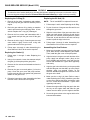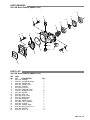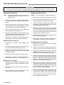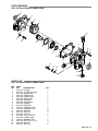
1
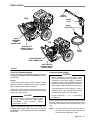
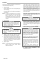
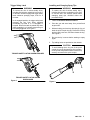
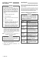
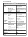
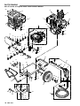
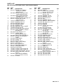
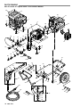
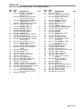
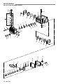
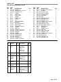
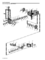
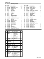
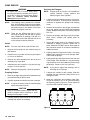
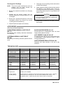
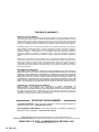
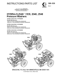
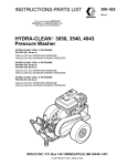
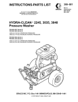
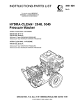
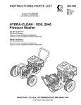
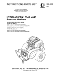
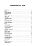
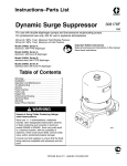
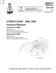
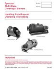
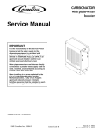
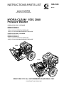
INSTRUCTIONS-PARTS LIST
308–523
Rev A
This manual contains IMPORTANT
WARNINGS and INSTRUCTIONS
READ AND RETAIN FOR REFERENCE
HYDRA-CLEAN 1535, 2040
Pressure Washer
HYDRA-CLEAN 1535, 5 HP ENGINE
P/N 800–670, Series A
P/N 800–671, Series A
1500 psi (103 bar) OPERATING PRESSURE
1900 psi (131 bar) MAXIMUM WORKING PRESSURE
HYDRA-CLEAN 2040, 8 HP ENGINE
P/N 800–672, Series A
P/N 800–674, Series A
2000 psi (138 bar) OPERATING PRESSURE
2400 psi (165 bar) MAXIMUM WORKING PRESSURE
1535
2040
GRACO INC. P.O. Box 1441 MINNEAPOLIS, MN 55440–1441
COPYRIGHT 1990, GRACO INC.
WARNING
HIGH PRESSURE SPRAY CAN CAUSE SERIOUS INJURY.
FOR PROFESSIONAL USE ONLY. OBSERVE ALL WARNINGS.
Read and understand all instruction manuals before operating equipment.
FLUID INJECTION HAZARD
General Safety
Pressure Relief Procedure
This pressure washer generates very high fluid
pressure. Spray from the gun, leaks or ruptured
components can inject fluid through your skin and into
your body and cause extremely serious bodily injury
including the need for amputation. Also, fluid injected or
splashed into the eyes or on the skin can cause serious
damage.
To reduce the risk of serious bodily injury, including fluid
injection and splashing in the eyes or on the skin, always
follow this procedure whenever you stop spraying for
more than 10 minutes, when shutting down, and before
checking or repairing any part of the system.
NEVER point the spray gun or wand at anyone or at any
part of the body. NEVER put hand or fingers over the
spray tip.
ALWAYS follow the Pressure Relief Procedure,
before cleaning or servicing any part of the sprayer.
NEVER try to stop or deflect leaks with your hand or
body.
Be sure equipment safety devices are operating
properly before each use.
Medical Treatment
If any fluid appears to penetrate your skin, get
EMERGENCY MEDICAL TREATMENT AT ONCE. DO
NOT TREAT AS A SIMPLE CUT. Tell the doctor exactly
what fluid was injected.
NOTE TO PHYSICIAN: Injection in the skin is a
traumatic injury. It is important to treat the injury
surgically as soon as possible. Do not delay
treatment to research toxicity. Toxicity is a concern
with some exotic coatings injected directly into the
bloodstream. Consultation with a plastic surgeon
or reconstructive hand surgeon may be advisable.
1. Engage the trigger safety latch.
2. Turn the sprayer off.
3. Remove the ignition cable from the spark plug.
4. Shut off the water supply.
5. Disengage the trigger safety latch and trigger the
gun to relieve pressure, and then engage the trigger
safety latch again.
6. Before long–term (overnight) storage or
transporting of unit, disconnect the water supply
and turn off the fuel supply valve.
Spray Gun Safety Devices
Be sure all gun safety devices are operating properly
before each use. Do not remove or modify any part of
the gun; this can cause a malfunction and result in
serious bodily injury.
SAFETY LATCH: Whenever you stop spraying for a
moment, always set the gun safety latch in the engaged
or “safe” position, making the gun inoperative. Failure to
properly set the safety latch can result in accidental
triggering of the gun.
SPRAY TIP SAFETY: Use extreme caution when
cleaning or changing spray tips. If a spray tip clogs while
spraying, engage the gun safety latch immediately.
ALWAYS follow the Pressure Relief Procedure and
then remove the spray tip to clean it.
EQUIPMENT MISUSE HAZARD
General Safety
System Pressure
Any misuse of the pressure washer or accessories,
such as overpressurizing, modifying parts, using
incompatible chemicals and fluids, or using worn or
damaged parts, can cause them to rupture and result in
fluid injection, splashing in the eyes or on the skin, or
other serious bodily injury, fire, explosion or property
damage.
This sprayer can develop high operating pressures. Be
sure that all spray equipment and accessories are rated
to withstand the maximum working pressure of this
sprayer. DO NOT exceed the maximum working
pressure of any component or accessory used in the
system.
Chemical Compatibility
NEVER alter or modify any part of this equipment; doing
so could cause it to malfunction.
CHECK all spray equipment regularly and repair or
replace worn or damaged parts immediately.
ALWAYS wear protective eyewear and appropriate
clothing. If using a chemical injector, read and follow the
chemical
manufacturer’s
literature
for
recommendations on additional protective equipment,
such as a respirator.
BE SURE that all chemicals used in the chemical
injector are compatible with the wetted parts of the hose,
gun, wand and tip, as given in the Technical Data (inside
back cover). Always read the chemical manufacturer’s
literature before using any chemical in this pressure
washer.
HOSE SAFETY
High pressure fluid in the hoses can be very dangerous.
If the hose develops a leak, split or rupture due to any
kind of wear, damage or misuse, the high pressure
spray emitted from it can cause a fluid injection injury or
other serious bodily injury or property damage.
ALL FLUID HOSES MUST HAVE STRAIN RELIEFS
ON BOTH ENDS. The strain reliefs help protect the
hose from kinks or bends at or close to the coupling,
which can result in hose rupture.
TIGHTEN all fluid connections securely before each
use. High pressure fluid can dislodge a loose coupling or
allow high pressure spray to be emitted from the
coupling.
NEVER use a damaged hose. Before each use, check
entire hose for cuts, leaks, abrasion, bulging cover, or
damage or movement of the hose couplings. If any of
these conditions exist, replace the hose immediately.
DO NOT try to recouple high pressure hose or mend it
with tape or any other device. A repaired hose cannot
contain the high pressure fluid.
HANDLE AND ROUTE HOSES CAREFULLY. Do not
pull on hoses to move the pressure washer. Do not use
chemicals which are not compatible with the inner tube
and cover of the hose. DO NOT expose Graco hose to
temperatures above 200_ F (93_ C) or below –40_ F
(–40_ C).
FUEL AND EMISSION HAZARDS
NEVER fill the fuel tank while the unit is running or hot.
The fuel used in this unit is combustible and when spilled
on a hot surface can ignite and cause a fire. ALWAYS fill
tank slowly to avoid spilling.
NEVER alter the throttle setting, which is factory set.
Tampering with this adjustment can damage the
pressure washer and will void the warranty.
NEVER operate the unit in a closed building. The
exhaust contains carbon monoxide, a poisonous,
odorless, invisible gas which can cause serious injury or
death if inhaled.
MOVING PARTS HAZARD
Moving parts can pinch or amputate fingers or other
body parts. KEEP CLEAR of moving parts when starting
or operating the pressure washer.
Pressure Relief Procedure before checking or
servicing the pressure washer to prevent discharging
high pressure fluid from the gun.
NEVER operate the pressure washer without all guards
and interlocks installed and functioning. Follow the
TERMS
WARNING: Alerts user to avoid or correct conditions
that could cause bodily injury.
NOTE:
Identifies helpful procedures and information.
CAUTION: Alerts user to avoid or correct conditions
that could cause damage to the equipment.
IMPORTANT
United States Government safety standards have been adopted under the Occupational Safety and Health Act. These
standards—particularly the General Standards, Part 1910, and the Construction Standards, Part 1926—should be
consulted.
4 308-523
INSTALLATION
QUICK
COUPLER
2040
SPRAY
GUN
QUICK
COUPLER
HIGH
PRESSURE
HOSE
CONNECTION
1535
INLET WATER
CONNECTION 3/4”
GARDEN HOSE
SPRAY
HOSE
HIGH PRESSURE
HOSE CONNECTION
INLET WATER
CONNECTION 3/4”
GARDEN HOSE
Figure 1
Check for Shipping Damage
Check the unit for any damage that may have occurred
in shipping. Notify the carrier immediately if there is
any damage.
Connect to Water Supply
CAUTION
If you are using a downstream chemical injector, install it
between the pump unloader and the high pressure
hose, using the quick couplers provided.
Before attaching to the water supply, check
your local plumbing code regarding cross–
connection to the water supply. A backflow
preventer, P/N 801–133, is available to prevent
backflow of contaminated water into the fresh
water supply. Install it upstream from the pump.
Connect the high pressure hose between the pump
outlet and the gun inlet. Both of these connections are
made with quick couplers.
If inlet water pressure is over 60 psi (4.1 bar) a
regulating water valve, P/N 800–258, must be
installed at the garden hose connection.
CAUTION
Do not exceed 160_ F (70_ C) inlet water
temperature.
Set Up
Up to 100 ft (30 m) of high pressure hose may
be used. Longer hoses may affect sprayer
performance,
and
chemical
injector
performance, if used.
Install the appropriate spray tip on the wand. See
Installing and Changing Spray Tips. If you are using a
sandblaster kit, see its separate manual for installation
instructions.
Connect a hose with at least a 3/4 inch (19 mm) ID from
the water supply to the unit’s 3/4 inch garden hose inlet.
The supply hose should not be more than 50 ft (15 m)
long.
NOTE:
The water source at the unit must have a
minimum flow rate equal to that of the unit (see
Technical Data, inside back cover).
STARTUP
Always use this start-up procedure to ensure that the
unit is started safely and properly.
1. Check oil levels.
Engine: Add SAE 30 or 10W–30 weight detergent
oil as necessary.
Pump: Add SAE 20 or 30 weight non–detergent oil
as necessary.
NOTE:
All units are equipped with a low–oil sensor
that shuts the engine off if the oil level falls
below a certain level. If the unit stops
unexpectedly, check both the oil and the fuel
levels. Check the oil level each time the unit is
refueled.
If the engine is cold, completely close the engine
choke. Grasp the starter rope, brace one foot on the
pressure washer chassis and pull rope rapidly and
firmly. Continue holding the rope as it returns. Pull
and return the rope until the engine starts. In cool
weather, the choke may have to be kept closed for
10 to 30 seconds before opening it to keep the
engine running. Otherwise, open the choke as soon
as the engine starts.
If the engine is warm, leave the choke open, or just
partly close it. Start the engine as described in the
preceding paragraph. When it starts, be sure to
open the choke completely.
CAUTION
On recoil start engines, never let the starter rope
return by itself. It could jam the recoil system.
2. Check fuel level.
WARNING
DO NOT refuel a hot engine. Refueling a hot
engine could cause a fire. Use only fresh, clean
regular or unleaded gasoline. Close the fuel
shutoff valve during refueling.
3. Turn on the water supply.
7. ALWAYS engage the gun’s trigger safety latch
whenever you stop spraying, even for a moment, to
reduce the risk of fluid injection or splashing in the
eyes or on the skin if the gun is bumped or triggered
accidentally.
8. ALWAYS observe the following CAUTIONS to
avoid costly damage to the pressure washer.
CAUTION
CAUTION
Never run the unit dry. Costly damage to the
pump will result. Always be sure the water
supply is completely turned on before
operating.
DO NOT allow the pressure washer to idle for
more than 10 minutes. Doing so may cause the
recirculating water to overheat and seriously
damage the pump. Turn off the pressure
washer if it will not be spraying or cleaning at
least every 10 minutes. If heated inlet water is
used, reduce this time further.
4. Trigger the gun until water sprays from the tip
indicating that the air is purged from the system.
5. Open the fuel shutoff valve. Be sure the spark plug
ignition cable is pushed firmly onto the spark plug.
On those units equipped with an ignition shutoff
switch, put the switch in the “on” position and put the
throttle in the “run” position.
6. Start the engine.
NOTE:
For easier starting, have one person start the
pressure washer while another person
triggers the spray gun.
DO NOT run the pump dry, which will quickly
damage the pump. Be sure the water supply is
fully turned on before starting the pump.
DO NOT operate the pressure washer with the
inlet water screen removed. This screen helps
keep abrasive sediment out of the pump, which
could clog or scratch the pump. Keep this
screen clean.
DO NOT pump caustic materials; such
materials may corrode the pump components.
9. See the chemical injector or sandblaster kit manual
for detailed cleaning information if these
accessories are used.
Trigger Safety Latch
WARNING
To reduce the risk of serious bodily injury,
including fluid injection, splashing in the eyes or
on the skin, ALWAYS engage the trigger safety
latch whenever spraying stops, even for a
moment.
In the engaged position, the trigger safety latch
prevents the gun from being triggered
accidentally by hand or if it is dropped or
bumped. Be sure the latch is pushed fully down
when engaging it or it cannot prevent the gun
from being triggered. See Figure 2.
Installing and Changing Spray Tips
WARNING
To reduce the risk of serious bodily injury,
including fluid injection or splashing in the eyes
or onto the skin, use extreme caution when
changing spray tips. ALWAYS follow the
procedure below.
1. Follow the Pressure Relief Procedure.
2. Point the gun and wand away from yourself and
anyone else.
3. Without holding your hand over the spray tip (A), pull
back the quick coupler ring (B). Remove the old tip
and/or install a new one, and then release the ring.
See Figure 3.
4. Be sure the tip is secure before starting to spray
again.
5. Tip holding holes are provided on the chassis.
CAUTION
TRIGGER SAFETY LATCH SHOWN ENGAGED
To avoid blowing the o–ring out of the quick
coupler, due to the high pressure in the system,
never operate the pressure washer without a tip
securely mounted in the quick coupler.
A
B
TRIGGER SAFETY LATCH SHOWN
DISENGAGED
Figure 2
Figure 3
SHUTDOWN, FLUSHING
AND STORAGE
MAINTENANCE
Observing regular maintenance intervals helps ensure
that you get maximum performance and life from the
pressure washer.
WARNING
Pressure Relief Procedure
To reduce the risk of serious bodily injury,
including fluid injection and splashing in the
eyes, or on the skin, always follow this
procedure whenever you stop spraying for
more than 10 minutes, when shutting down,
and before checking or repairing any part of the
system.
There is a break–in period for the engine, pump and
gear reducer (if used). After changing the oil in these
components following their respective break–in periods,
the interval between required changes is longer.
If the unit is operating in dusty conditions, these
maintenance checks should be made more often.
WARNING
1. Engage the trigger safety latch.
To reduce the risk of serious bodily injury,
including fluid injection, splashing in the eyes or
on the skin or injury from moving parts, always
follow the Pressure Relief Procedure
Warning before proceeding.
2. Turn the sprayer off.
3. Remove the ignition cable from the spark
plug.
4. Shut off the water supply.
5. Disengage the trigger safety latch and
trigger the gun to relieve pressure, and then
engage the trigger safety latch again.
6. Before long–term (overnight) storage or
transporting of unit, disconnect the water
supply, and turn off the fuel supply valve.
1. If the pressure washer will be exposed to freezing
temperatures, drain all water out of the pump. If it
must be stored in freezing temperatures, flush the
unit with a 50% anti–freeze solution. Relieve
pressure. Flush the pressure washer before using it
again to remove the anti–freeze.
NOTE:
An anti–freeze flush kit, P/N 802–327, is
available to make flushing easier.
CAUTION
2. After each use, wipe all surfaces of the pressure
washer with a clean, damp cloth.
maintenance.
What to do
Daily
Clean water inlet screen and
filter. Check engine and pump oil
levels. Fill as necessary. Check
gasoline level. Fill as necessary.
After first 5
hours of
operation
Change engine break–in oil. Drain
oil when warm. Use SAE 30 or
10W–30 detergent oil.
Each 25 hours
of operation
Clean and remove air cleaner
foam. Wash with water and
detergent. Dry thoroughly. Rub
with oil and squeeze to distribute
oil.
After first 50
hours of
operation
Change pump break–in oil. Use
SAE 20 or 30 non–detergent oil.
Change gear reducer oil. Use
SAE 90 gear oil.
Each 100 hours Clean or replace paper air
of operation
cleaner cartridge. Tap gently to
or 3 months
remove dirt. Change engine oil.
Use SAE 30 or 10W–30
detergent oil.
If water does freeze in the pressure washer,
thaw it in a warm room before trying to start it.
DO NOT pour hot water on or into the pump; it
may crack the ceramic plungers!
3. Perform the appropriate
maintenance chart.
Interval
See
Each 500 hours Change pump oil. Use SAE 20 or
of operation
30 non–detergent oil. Change
or 6 months
gear reducer oil. Use SAE 90
gear oil.
TROUBLESHOOTING CHART
WARNING
To reduce the risk of serious bodily injury, including fluid injection, splashing in the eyes or on the skin or
injury from moving parts, always follow the Pressure Relief Procedure Warning before proceeding.
CAUSE
PROBLEM
Engine will not start or
is hard to start
No gasoline in fuel tank or carburetor.
SOLUTION
Dirty air cleaner filter.
Spark plug dirty, wrong gap or wrong type.
Spray gun closed.
Fill the tank with gasoline, open fuel shut off valve.
Check fuel line and carburetor.
Add to proper level.
Move switch to start position.
Drain fuel tank and carburetor. Use new fuel and dry
spark plug.
Open choke and crank engine several times to clear
out gas.
Remove and clean.
Clean, adjust the gap or replace.
Trigger spray gun.
Engine misses or
lacks power
Partially plugged air cleaner filter.
Spark plug dirty, wrong gap or wrong type.
Remove and clean.
Clean, adjust the gap or replace.
Low pressure and/or
pump runs rough
Worn or wrong size tip.
Inlet filter clogged.
Worn packings, abrasives in water or
natural wear.
Inadequate water supply.
Fouled or dirty inlet or discharge valves.
Even a small particle can cause the valve
to stick.
Restricted inlet.
Worn inlet or discharge valves.
Leaking high pressure hose.
Replace with tip of proper size.
Clean. Check more frequently.
Check filter. Replace packings. See PUMP SERVICE.
Water leakage from
under pump manifold
Worn packings.
Install new packings. See PUMP SERVICE.
Water in pump
Humid air condensing inside crankcase.
Worn packings.
Oil seals leaking.
Change oil as specified in MAINTENANCE.
Install new packings. See PUMP SERVICE.
Install new oil seals. See PUMP SERVICE.
Frequent or premature
failure of the packings
Scored, damaged or worn plungers.
Abrasive material in the fluid being pumped.
Inlet water temperature too high.
Overpressurizing pump.
Strong surging at the
inlet and low pressure
on the discharge side
Foreign particles in the inlet or discharge
valve or worn inlet and/or discharge valves.
Clean or replace valves. See PUMP SERVICE.
Oil leakage between
the gear reducer cover
and case
Worn gasket.
Replace the gasket. See SERVICE SECTION.
Oil leakage between
the gear reducer cover
and the pump
Worn oil seals and/or o-ring.
Replace oil seals and/or o-ring. See SERVICE
SECTION.
Oil leakage between
the gear reducer case
and the engine
Worn oil seal.
Replace oil seal. See SERVICE SECTION.
Low oil
Start/Stop switch in Stop position.
Water in gasoline or old fuel.
Choked improperly. Flooded engine.
Check water flow rate to pump.
Clean inlet and discharge valve assemblies. Check
filter.
Check garden hose, may be collapsed or kinked.
Replace worn valves.
Replace high pressure hose.
Install new plungers. See PUMP SERVICE.
Install proper filtration on pump inlet plumbing.
Check water temperature; may not exceed 160F.
Do not modify any factory–set adjustments. See
EQUIPMENT MISUSE HAZARD.
Excessive pressure due to partially plugged Clean or replace tip. See Installing and Changing
or damaged tip.
Spray Tips.
Pump running too long without spraying.
Never run pump more than 10 minutes without
spraying.
Running pump dry.
Do not run pump without water.
PARTS DRAWING
800–672 & 800–674 Hydra–Clean 2040 Pressure Washer
58
57
57
15
55
1
1
58
53
2
4
6
3
54
9
18
17
4
6
10
14
12
11
13
11
18
20
19
46
6
23
16
24
8
7
25
26
22
44
21
28
59
47
64
46
32
66
31
5
6
61
60
62
48
49
6
52
63
45
39
6
36
29
37
36
50
51
36
35
10 308-523
42
46
43
27
30
35
27
30
41
67
36
38
40
40
29
34
10
PARTS LIST
800–672 & 800–674 Hydra–Clean 2040 Pressure Washer
REF
NO.
1
2
3
4
5
6
7
8
9
10
11
12
13
14
15
16
17
18
19
20
21
22
23
24
25
26
27
28
29
30
31
32
PART
NO.
DESCRIPTION
QTY
802–141 ENGINE, 8 hp, Briggs &
Stratton I/C (used on
800–672 only)
1
802–998 ENGINE, 8 hp, Honda OHV
(used on 800–674 only)
1
802–299 PUMP & GEAR REDUCER
ASSEMBLY (incl. 3, 13)
1
802–143 GEAR REDUCER (see page 17) 1
802–127 SCREW, Cap, hex hd.
5/16–18 x 1-3/4
4
100–214 WASHER, Lock 5/16
6
18
100–527 WASHER, Flat 5/16
1
802–140 BRACKET, Support
2
801–367 BUMPER, Rubber
1
801–907 WASHER, Flat
1
801–905 ADAPTER, 3/8 G x 3/8 NPT
2
156–849 NIPPLE, Hex 3/8
802–315 UNLOADER, Preset 2000 psi
1
803–405 PUMP ASSEMBLY, 2000 psi
(see page 20)
1
1
801–709 PLUG, Square hd. 1/4
802–257 GUARD, Muffler
(used on 800–672 only)
1
2
801–568 QUICK COUPLER, Male 3/8
802–627 NIPPLE, Hex 3/8 NPSM x
1/4 NPT
1
1
803–869 HOSE, Bypass
1
801–622 CROSS, 1/2
1
801–523 NIPPLE, 1/2 x 2
1
800–115 VALVE, Thermal Relief
1
804–073 ADAPTER, 1/2
801–111 NUT, Garden Hose
1
1
801–110 ADAPTER, Garden Hose
804–051 STRAINER/FILTER
1
1
402–278 PLUG, Plastic
2
156–082 O–RING, Quick Coupler 3/8
1
154–594 O–RING, Quick Coupler 1/4
802–579 HOSE, High Pressure, 3/8 x 50’ 1
801–569 QUICK COUPLER, Female 3/8
(incl. 27)
2
800–392 GUN & WAND ASSEMBLY
(incl. 11, 59, 60, 61, 62, 63)
1
800–661 CHASSIS
1
REF
NO.
33
34
35
36
37
38
39
40
41
42
43
44
45
46
47
48
49
50
51
52
53
54
55
57
58
59
60
61
62
63
64
65
66
67
PART
NO.
DESCRIPTION
803–925 HANDLE
800–175 FRONT LEG ASSEMBLY
(incl. 35, 36, 50, 51, 67)
801–546 SCREW, Cap, hex hd.
3/8–16 x 1-1/4
100–023 WASHER, Flat 3/8
100–133 WASHER, Lock 3/8
100–307 NUT, Hex 3/8–16
802–139 AXLE
801–235 WASHER, Flat 5/8
106–062 WHEEL & TIRE ASSEMBLY
101–545 PIN, Cotter 1/8 x 1-1/2
104–811 HUB CAP
801–539 BUMPER
801–941 SCREW, Cap, hex hd.
5/16–18 x 1
111–040 NUT, Lock 5/16–18
801–012 GROMMET, Rubber
800–174 TIP ASSEMBLY, 00055
(incl. 64, 66)
800–173 TIP ASSEMBLY, 15055
(incl. 64, 66)
801–858 BRACKET, Front Leg
801–504 BUMPER, Rubber
179–885 LABEL, Chassis
802–781 KEY, Square 1/4 x 2
803–083 LABEL, Keep From Freezing
181–867 LABEL, Warning
802–363 LABEL, Caution
804–274 LABEL, Graco Cleaning
Systems
801–009 QUICK COUPLER,
Female 1/4 (incl. 28)
801–134 WAND, 32”
801–674 SLEEVE, 28”
804–272 LABEL, Model 2040
803–350 GUN, Spray (see Instruction
Manual 308–511)
801–090 QUICK COUPLER, Male 1/4
801–730 TIP, Spray 00055
801–729 TIP, Spray 15055
801–499 NUT, Lock 3/8–16
QTY
1
1
5
10
4
4
1
4
2
2
2
1
4
10
4
1
1
1
1
1
1
1
1
1
1
1
1
1
1
1
4
1
1
1
308-523 11
PARTS DRAWING
800–670 & 800–671 Hydra–Clean 1535 Pressure Washer
58
57
55
1
57
55
1
53
2
59
54
3
4
6
6
4
67
6
9
18
14
17
58
10
11
15
11
7
12
46
18
16
20
6
23
8
24
25
26
22
44
21
47
46
32
64
6
56
61
60
6
63
48
65 49
66
45
52
39
40
31
36
33
16
6
35
46
41
30
67
36
29
40
42
34
38
37
36
50
51
36
35
12 308-523
43
PARTS LIST
800–670 & 800–671 Hydra–Clean 1535 Pressure Washer
REF
NO.
1
2
3
4
5
6
7
8
9
10
11
12
13
14
15
16
17
18
19
20
21
22
23
24
25
26
27
28
29
30
31
32
PART
NO.
DESCRIPTION
QTY
803–239 ENGINE, 5 hp, Briggs &
Stratton I/C (used on
800–670 only)
1
803–264 ENGINE, 5 hp, Honda OHV
(used on 800–671 only)
1
802–300 PUMP & GEAR REDUCER
ASSEMBLY (incl. 3, 13)
1
802–266 GEAR REDUCER (see page ) 1
802–127 SCREW, Cap, hex hd.
5/16–18 x 1-3/4
4
100–214 WASHER, Lock 5/16
6
18
100–527 WASHER, Flat 5/16
1
803–892 BRACKET, Support
2
801–367 BUMPER, Rubber
1
801–907 WASHER, Flat
1
801–905 ADAPTER, 3/8 G x 3/8 NPT
2
156–849 NIPPLE, Hex 3/8
802–316 UNLOADER, Preset 1500 psi
1
802–265 PUMP ASSEMBLY, 1500 psi
(see page 18)
1
1
801–709 PLUG, Square hd. 1/4
803–245 GUARD, Muffler (used on
800–670 only)
1
2
801–568 QUICK COUPLER, Male 3/8
802–627 NIPPLE, Hex 3/8 NPSM x
1/4 NPT
1
1
803–869 HOSE, Bypass
1
801–622 CROSS, 1/2
1
801–523 NIPPLE, 1/2 x 2
1
800–115 VALVE, Thermal Relief
1
804–073 ADAPTER, 1/2
801–111 NUT, Garden Hose
1
1
801–110 ADAPTER, Garden Hose
804–051 STRAINER/FILTER
1
1
402–278 PLUG, Plastic
2
156–082 O–RING, Quick Coupler 3/8
1
154–594 O–RING, Quick Coupler 1/4
802–579 HOSE, High Pressure, 3/8 x 50’ 1
801–569 QUICK COUPLER,
Female 3/8 (incl. 27)
2
800–392 GUN & WAND ASSEMBLY
(incl. 11, 59, 60, 61, 62, 63)
1
800–661 CHASSIS
1
REF
NO.
33
34
35
36
37
38
39
40
41
42
43
44
45
46
47
48
49
50
51
52
53
54
55
56
57
58
59
60
61
63
64
65
66
67
PART
NO.
DESCRIPTION
803–925 HANDLE
800–175 FRONT LEG ASSEMBLY
(incl. 35, 36, 50, 51, 67)
801–546 SCREW, Cap, hex hd.
3/8–16 x 1-1/4
100–023 WASHER, Flat 3/8
100–133 WASHER, Lock 3/8
100–307 NUT, Hex 3/8–16
802–139 AXLE
801–235 WASHER, Flat 5/8
106–062 WHEEL & TIRE ASSEMBLY
101–545 PIN, Cotter 1/8 x 1-1/2
104–811 HUB CAP
801–539 BUMPER
801–941 SCREW, Cap, hex hd.
5/16–18 x 1
111–040 NUT, Lock 5/16–18
801–012 GROMMET, Rubber
800–174 TIP ASSEMBLY, 00055
(incl. 64, 65)
800–173 TIP ASSEMBLY, 15055
(incl. 64, 66)
801–858 BRACKET, Front Leg
801–504 BUMPER, Rubber
179–885 LABEL, Chassis
802–781 KEY, Square 1/4 x 2
803–083 LABEL, Keep From Freezing
181–867 LABEL, Warning
801–723 LABEL, Model 1535
804–274 LABEL, Caution
802–373 LABEL, Graco Cleaning
Systems
801–009 QUICK COUPLER,
Female 1/4 (incl. 28)
801–134 WAND, 32”
801–674 SLEEVE, 28”
803–350 GUN, Spray (see Instruction
Manual 308–511)
801–090 QUICK COUPLER, Male 1/4
801–730 TIP, Spray 00055
801–729 TIP, Spray 15055
801–499 NUT, Lock 3/8–16
QTY
1
1
5
10
4
4
1
4
2
2
2
1
4
10
4
1
1
1
1
1
1
1
1
1
1
1
1
1
1
1
4
1
1
1
308-523 13
GEAR REDUCER SERVICE (Model 1535)
WARNING
To reduce the risk of serious bodily injury, including fluid injection, splashing in the eyes or on the skin or injury
from moving parts, always follow the Pressure Relief Procedure Warning on page 2 before proceeding.
Replacing the O–Ring (5)
Replacing the Oil Seal (10)
1. Remove the four bolts, lockwashers and washers.
Pull the pump and gear reducer assembly off the
engine.
NOTE:
2. Drain the gear reducer oil by placing a container
under it and removing the drain plug with a 22 mm
wrench. Replace the o–ring (16) if damaged.
3. Remove the four screws and lockwashers with a
6 mm wrench and pull the gear case off the gear
cover.
4. Remove the old o–ring (5). Clean the gear cover and
case surface. Lightly coat the new o–ring with
grease and install it in the gear case.
5. Follow steps 4 through 6 under Assembling the
Gear Reducer if this is all the service required.
Replacing the Gasket (1)
1. Follow steps 1 through 3 under Replacing the
O–Ring.
2. Using a 4 mm wrench, loosen the setscrew and pull
the gear (4) off the pump with a gear puller.
3. Remove the four screws and lockwashers from the
gear cover.
4. Remove the gear cover and gasket (1) from the
pump. Clean the gear cover and pump surface.
Lightly coat both sides of the gasket with grease and
install it on the gear cover.
5. Follow the instructions under Assembling the Gear
Reducer if this is all the service required.
The oil seal MUST be replaced if removed.
1. Follow steps 1 and 2 under Replacing the O–Ring.
2. Pry the oil seal out of the gear case. Be careful not to
damage the gear case.
3. Wipe the inner surface of the gear case clean, then
lightly coat it with grease. Place the oil seal into the
gear case. Use a socket, placed against the surface
of the seal, to push the seal into the case until its top
surface is past the ridge in the bore.
4. Follow steps 4 through 6 under Assembling the
Gear Reducer if this is all the service required.
Assembling the Gear Reducer
1. Make sure the gasket is properly placed on the gear
cover. Refer to step 4 under Replacing the Gasket.
Then, install the gear cover on the pump shaft.
2. Align the holes in the gear cover with the holes in the
pump. Apply low strength Loctite (blue) on the
screw threads and secure the cover with the four
screws and lockwashers. Tighten them oppositely
and evenly.
3. Align the gear’s slot with the key on the pump shaft
and slide the gear onto the shaft, up to the pump’s
shoulder. Apply low strength Loctite on the
setscrew threads and tighten the setscrew to lock
the gear on the shaft.
4. Make sure the o–ring is in place. Refer to step 4
under Replacing the O–Ring. Install the gear case
on the cover, aligning the holes, and secure it with
the four screws and lockwashers. Tighten them
oppositely and evenly.
5. Grease the engine shaft. Align the gear’s slot with
the key on the engine shaft and slide the gear
reducer onto the shaft, up to the engine’s shoulder.
6. Secure the gear reducer to the engine with the four
bolts and lockwashers.
14 308-523
PARTS DRAWING
802–266 Gear Reducer (Model 1535)
10
6
9
11
8
12
13
14
20
7
3
19
16
15
5
17
8
18
4
2
1
PARTS LIST
802–266 Gear Reducer (Model 1535)
REF
NO.
1
2
3
4
5
6
7
8
9
10
11
12
13
14
15
16
17
18
19
20
PART
NO.
802–350
802–351
802–334
802–352
802–353
801–659
802–354
100–527
802–342
802–355
802–356
802–357
802–358
802–359
801–484
802–344
802–345
802–331
802–360
803–278
DESCRIPTION
GASKET
COVER, Mounting
SCREW, Set
GEAR, Pump
O–RING
DIPSTICK
CASE, Mounting
WASHER, Lock
SCREW
SEAL, Oil
RING, Snap
RING, Snap
BEARING
GEAR, Engine
CAP, G 3/8 BSP
O–RING
GAUGE, Sight
BOLT, 5/16–24 x 1”
SCREW
SEAL, Oil
QTY
1
1
1
1
1
1
1
8
4
1
1
1
1
1
1
1
1
4
4
4
308-523 15
GEAR REDUCER SERVICE (Model 2040)
WARNING
To reduce the risk of serious bodily injury, including fluid injection, splashing in the eyes or on the skin or injury
from moving parts, always follow the Pressure Relief Procedure Warning on page 2 before proceeding.
Replacing the Gasket (9)
Replacing the Oil Seal (14)
NOTE:
NOTE:
To maintain a good seal, the gasket must be
replaced whenever the gear reducer is
disassembled.
1. Remove the four bolts, lockwashers and washers.
Pull the pump and gear reducer assembly off the
engine.
2. Drain the gear reducer oil by placing a container
under it and removing the drain plug with a 22 mm
wrench. Replace the o–ring (15) if damaged.
3. Remove the nine screws with a 6 mm wrench and
pull the gear case off the gear cover.
4. Remove the old gasket (9). Clean the gear cover
and case surface. Lightly coat the new gasket with
grease and install it in on the gear case.
5. Follow steps 5 through 7 under Assembling the
Gear Reducer if this is all the service required.
Replacing the Oil Seals (21)
1. Follow steps 1 through 3 under Replacing the
Gasket.
2. Loosen the setscrew, using a 4 mm wrench, and pull
the gear (4) off the pump with a gear puller.
3. Using a 6 mm wrench, remove the four screws.
Keep them separate from the other nine screws
removed previously.
4. Remove the four oil seals (21) and replace them.
5. Follow steps 2 through 7 under Assembling the
Gear Reducer if this is all the service required.
Replacing the O–Ring (1)
1. Follow the instructions under Replacing the Gasket
and Replacing the Oil Seals to disassemble the gear
reducer.
2. Pull the gear cover off the pump and replace the
o–ring (1).
3. Follow instructions under Assembling the Gear
Reducer if this is all the service required.
The oil seal MUST be replaced if removed.
1. Follow steps 1 and 3 under Replacing the Gasket.
2. Remove the snap ring (6) from the gear case, using
a snap ring pliers. Pull the gear and bearing.
3. Push the seal from the inside to the outside of the
gear case by placing screwdriver against the seal
and lightly tapping it with hammer.
4. Wipe the inner surface of the case clean, then lightly
coat it with grease. Place the oil seal into the gear
case. Use a socket, placed against the surface of
the seal, to push the seal into the case until its top
surface is past the ridge in the bore.
5. Place the gear and bearing back into the gear case
and install the snap ring (6).
6. Follow steps 4 through 7 under Assembling the
Gear Reducer if this is all the service required.
Assembling the Gear Reducer
1. Grease the o–ring and make sure it’s properly
placed on the gear cover.
2. Place the four oil seals and screws in the gear cover.
Place the o–ring on the screw to hold it in the cover.
3. Apply low strength Loctite (blue) on the screw
threads, align the screws with the holes in the pump,
and tighten the screws oppositely and evenly.
4. Grease the pump shaft. Align the gear’s slot with the
key on the pump shaft and slide the gear onto the
shaft, up to the pump’s shoulder. Apply low strength
Loctite on the setscrew threads and tighten the
setscrew to lock the gear on the shaft.
5. Make sure the gasket is in place (refer to step 4
under Replacing the Gasket). Install the gear cover
on the case, aligning the holes, and secure it with
the nine screws and lockwashers. Tighten the
screws evenly in a crisscross pattern.
6. Grease the engine shaft. Align the gear’s slot with
the key on the engine shaft and slide the gear
reducer onto the shaft, up to the engine’s shoulder.
7. Secure the gear reducer to the engine with the four
bolts, lockwashers and washers.
16 308-523
PARTS DRAWING
802–143 Gear Reducer (Model 2040)
1
2
3
4
10
21
20
5
11
6
12
7
13
8
9
14
17
19
12
18
15
16
PARTS LIST
802–143 Gear Reducer (Model 2040)
REF
NO.
1
2
3
4
5
6
7
8
9
10
11
12
13
14
15
16
17
18
19
20
21
PART
NO.
802–332
802–333
802–334
802–335
802–336
802–337
802–338
802–339
802–340
801–475
802–341
100–527
802–342
802–343
802–344
801–484
802–345
100–214
802–331
802–346
802–347
DESCRIPTION
O–RING
COVER, Mounting
SCREW, Set
GEAR, Pump
GEAR, Engine
RING, Snap
BEARING
RING, Snap
GASKET
DIPSTICK
CASE, Mounting
WASHER, Lock
SCREW
SEAL, Oil
O–RING
CAP, G 3/8 BSP
GAUGE, Sight
WASHER, Flat
BOLT, 5/16–24 x 1”
SCREW
SEAL, Oil
QTY
1
1
1
1
1
1
1
1
1
1
1
13
9
1
1
1
1
4
4
4
4
308-523 17
PARTS DRAWING
802–265 Pump Assembly, 1500 psi
10
24
9
23
8
18
19
7
11
20
21
6
22
5
13
4
2
1
14
14
12
47
3
12
15
16
17
48
52
49
51
11
10
50
9
22
45
18
21
44
19
26
29
25
37
33
31
34
35
36
32
28
27
43
42
28
41
18 308-523
40
39
38
30
PARTS LIST
802–265 Pump Assembly, 1500 psi
REF
NO.
1
2
3
4
5
6
7
8
9
10
11
12
13
14
15
16
17
18
19
20
21
22
23
24
25
26
PART
NO.
DESCRIPTION
802–319 MANIFOLD
801–651 SCREW, Cap, socket hd.
801–652 WASHER, Lock
KIT 1
O–RING
KIT 1
SEAT, Valve
KIT 1
PLATE, Valve
KIT 1
SPRING
KIT 1
GUIDE, Valve
KIT 4
O–RING
KIT 4
CAP
KIT 1
VALVE ASSEMBLY
KIT 27, 19PACKING
KIT 27
RETAINER, Packing
KIT 27
RING, Head
KIT 27
RETAINER, Packing
KIT 27
O–RING
KIT 23
SEAL, Oil
803–265 SCREW, Cap, hex hd
803–266 COVER, Crankcase
803–267 SPACER
803–268 O–RING
803–269 BEARING, Ball
803–326 CRANKCASE
801–659 DIPSTICK
803–327 GASKET, Cover
802–526 COVER, Crankcase
QTY
1
8
8
8
2
1
2
2
1
1
1
1
Kit
No.
Repair Kit
Part No.
Ref
No.
Description
Qty.
1
801–472
Valve
4
5
6
7
8
11
O–ring
Seat, valve
Plate, valve
Spring
Guide, valve
Valve Assy.
6
6
6
6
6
6
4
802–306
Valve Cap
9
10
O–ring
Cap
6
6
6
801–474
Plunger
Repair
28
41
42
43
O–ring
Ring, backup
Washer
Screw, piston
3
3
3
3
19
801–662
Packing
12
Packing
6
23
801–658
Oil Seal
17
Seal, oil
6
27
801–487
Packing &
Retainer
12
13
14
15
16
Packing
Retainer, packing
Ring, head
Retainer, packing
O–ring
2
1
1
1
1
REF
NO.
27
28
29
30
31
32
33
34
35
36
37
38
39
40
41
42
43
44
45
47
48
49
50
51
52
PART
NO.
803–273
KIT 6
802–345
802–793
803–328
803–275
802–794
803–276
803–277
803–278
803–279
803–330
801–489
801–661
KIT 6
KIT 6
KIT 6
803–281
803–282
802–317
802–318
801–484
801–482
801–483
801–485
DESCRIPTION
SCREW, Cap, socket hd.
O–RING
GAUGE, Sight
PLUG, Oil Drain
CRANKSHAFT
PIN, Wrist
KEY
ROD, Connecting
WASHER, Flat
WASHER, Lock
SCREW, Cap, socket hd.
GUIDE, Piston
WASHER, Flinger
PLUNGER, Ceramic
RING, Backup
WASHER
SCREW, Piston
SPACER
SEAL, Crankshaft
WASHER, Lock
SCREW, Cap, socket hd.
PLUG, Hex
PLUG, Hex
WASHER, Flat
WASHER, Flat
QTY
5
1
1
1
3
1
3
6
6
6
3
3
3
1
1
2
2
1
1
1
1
308-523 19
PARTS DRAWING
803–405 Pump Assembly, 2000 psi
10
9
20
19
18
8
12
7
11
13
14
6
5
4
1
45
44
46
47
45
50
3
2
44
54
43
42
16
49
17
53
9
11
52
10
51
40
15
41
14
39
12
29
28
21
23
26
22
37
38
31 36
35
34
33
32
24
25
27
31
30
PARTS LIST
803–405 Pump Assembly, 2000 psi
REF
NO.
1
2
3
4
5
6
7
8
9
10
11
12
13
14
15
16
17
18
19
20
21
22
23
24
25
26
27
PART
NO.
801–467
801–468
801–469
KIT 1
KIT 1
KIT 1
KIT 1
KIT 1
KIT 4
KIT 4
KIT 1
803–283
803–284
802–500
803–285
KIT 2
803–286
802–895
801–475
803–144
803–332
803–288
802–794
803–289
803–323
803–291
803–273
DESCRIPTION
MANIFOLD
SCREW, Cap, hex hd.
WASHER, Lock
O–RING
SEAT, Valve
PLATE, Valve
SPRING
GUIDE, Valve
O–RING
CAP
VALVE ASSEMBLY
SCREW, Cap, socket hd.
COVER, Crankcase
O–RING, Crankcase Cover
BEARING, Tapered Roller
SEAL, Oil
BUSHING, Piston
CRANKCASE
DIPSTICK
GASKET, Cover
CRANKSHAFT
RING, Retaining
KEY
PIN, Wrist
GUIDE, Piston
ROD, Connecting
SCREW, Cap, socket hd
QTY
1
8
8
8
1
2
2
1
1
1
1
1
6
1
3
3
3
5
Kit
No.
Repair Kit
Part No.
Ref
No.
Description
Qty.
1
801–472
Valve
4
5
6
7
8
11
O–ring
Seat, valve
Plate, valve
Spring
Guide, valve
Valve Assy.
6
6
6
6
6
6
2
801–473
Oil Seal
16
Seal, oil
3
3
802–511
Crankshaft
Seal
41
Seal, oil
2
4
802–306
Valve Cap
9
10
O–ring
Cap
6
6
6
801–474
Plunger
Repair
31
36
37
38
O–ring
Ring, backup
Washer
Screw, piston
3
3
3
3
8
801–486
Packing
44
Packing
6
28
801–487
Packing &
Retainer
42
43
44
45
46
47
O–ring
Retainer, packing
Packing
Ring, head
Retainer, packing
Ring, long life
1
1
2
1
1
1
REF
NO.
28
29
30
31
32
33
34
35
36
37
38
39
40
41
42
43
44
45
46
47
49
50
51
52
53
54
PART
NO.
DESCRIPTION
803–321 COVER, Crankcase
802–345 GAUGE, Sight
802–793 PLUG, Oil Drain
KIT 6
O–RING
803–294 SCREW, Cap, socket hd
801–652 WASHER, Lock
801–489 WASHER, Flinger
801–490 PLUNGER, Ceramic
KIT 6
RING, Backup
KIT 6
WASHER
KIT 6
SCREW, Piston
803–295 COVER, Crankcase
803–296 SHIM
KIT 3
SEAL, Oil
KIT 28
O–RING
KIT 28
RETAINER, Packing
KIT 28, 8 PACKING
KIT 28
RING, Head
KIT 28
RETAINER, Packing
KIT 28
RING, Long Life
802–305 SCREW, Cap, socket hd.
802–304 WASHER, Lock
801–482 PLUG, Hex
801–483 WASHER, Flat
801–484 PLUG, Hex
801–485 WASHER, Flat
QTY
1
1
1
6
6
3
3
1
2
2
2
1
1
1
1
308-523 21
PUMP SERVICE
WARNING
To reduce the risk of serious bodily injury,
including fluid injection, splashing in the eyes or
on the skin, or injury from moving parts, always
follow the Pressure Relief Procedure
Warning before proceeding.
NOTE:
NOTE:
The following metric wrenches are needed:
M10, M13 and M30. Repair kits are available.
Refer to the individual repair sections and the
pump parts page for more details. For the best
results, use all parts in the kits.
There are two different tool kits to aid in
servicing the pump. P/N 800–298 is used to
ease installation of packings. P/N 800–271
includes the items in 800–298 and tools to aid
in the removal of packing retainers.
Valves
NOTE:
For a set of six valves, order P/N 801–472.
1. Remove the hex plug from the manifold using an
M30 wrench.
2. Examine the o–ring under the hex plug and replace
it if it is cut or distorted.
3. Remove the valve assembly from the cavity; the
assembly may come apart.
4. Install the new valve. Install the o–ring and hex plug;
torque to 75 ft–lb (103 Nm).
NOTE:
NOTE:
1. Remove the eight capscrews and lockwashers from
the manifold using an M13 wrench.
2. Carefully separate the manifold from the crankcase.
It may be necessary to tap the manifold lightly
with a soft mallet to loosen.
Plunger repair kit, P/N 801–474 is available to
replace retainers, o–rings, washers and
backup rings for three cylinders.
1. Loosen the plunger retaining screw five to six turns,
using an M10 wrench. Push the plunger towards the
crankcase to separate the plunger and retaining
screw.
2. Remove the screw from the plunger and examine
the o–ring, backup ring and copper bearing/gasket
washer. Replace these parts, if necessary, using kit
801–474.
3. Remove the plunger and flinger from the plunger
shaft. Clean, examine and replace parts as
necessary.
4. Inspect the plunger shaft for oil leakage from the
crankcase. If leaking is obvious, replace the oil
seals. Otherwise, DO NOT remove these seals as
they cannot be reused. An oil seal kit is available to
replace the seals.
5. Lightly grease the flinger and oil seal, if it is being
replaced and replace them on the plunger shaft.
Then install the plunger.
6. Lightly grease the retaining screw and the outer end
of the plunger. Place the washer, o–ring and backup
ring around the screw and install the screw through
the plunger. Torque to 14.4 ft–lb (19.5 Nm).
NOTE:
Retorque the plug after 5 hours of operation.
Pumping Section
NOTE:
Servicing the Plungers
If you plan to replace the packings, refer to
Servicing the V–Packings.
7. Lubricate the outside of each plunger. Slide the
manifold onto the crankcase, being careful not to
damage the seals.
8. Install the capscrews and washers finger–tight.
Torque the screws to 21.7 ft–lb (29 Nm) following
the tightening pattern (Figure 4). Uneven tightening
may cause the manifold to bind or jam.
CAUTION
Keep the manifold properly aligned with the
ceramic plungers when removing to avoid
damage to the plunger or seals.
3. Carefully examine each plunger for any scoring or
cracking and replace as necessary.
Figure 4
5
1
4
7
8
3
2
6
Servicing the V–Packings
NOTE:
There are two types of packing kits: one is just
packings only, the other includes the
packings, rings and retainers.
1. Remove the manifold as outlined in the Pumping
Section.
5. Thoroughly clean the packing cavities and examine
for debris and damage.
6. Lightly grease the packing cavities and then replace
the packings in the following order: head ring,
v–packing, intermediate ring, head ring, v–packing
and packing retainer with the o–ring installed in the
retainer groove.
2. Carefully pull the packing retainer from the
manifold. Examine the o–ring and replace it if it is cut
or damaged.
3. Remove the v–packing and head ring. Pull out the
intermediate retainer ring. Remove the second
v–packing and second head ring.
CAUTION
Install the parts in the proper order and facing
the correct direction. Improperly installed parts
will cause a malfunction.
7. Reassemble the manifold as instructed in Servicing
the Plungers.
4. Inspect all parts and replace as necessary.
ACCESSORIES
(Must be purchased separately)
DOWNSTREAM CHEMICAL INJECTOR KIT
800–117
BACKFLOW PREVENTOR 801–133
For injecting harsh cleaning chemicals downstream
from the pump.
Prevent back–up of contaminated water into fresh
supply. Install upstream of pump.
ANTI–FREEZE FLUSH KIT 802–327
UPSTREAM CHEMICAL INJECTOR KIT
800–257
For injecting mild cleaning chemicals upstream into the
pump.
For flushing system with 50% anti–freeze solution prior
to transporting or storing pressure washer in below
freezing temperatures.
INLET PRESSURE REGULATOR 800–258
Regulates inlet water pressure to 60 psi (4 bar)
maximum.
TECHNICAL DATA
Model 800–670
Model 800–671
5 hp Honda OHV
Model 800–672
8 hp Briggs &
Stratton I/C
Model 800–674
Engine
(air–cooled, 4 cycle)
5 hp Briggs &
Stratton I/C
8 hp Honda OHV
Gasoline Tank Capacity
3 quarts (2.8 liter)
3.8 quarts (3.6 liter)
6 quarts (5.7 liter)
6.2 quarts (6 liter)
Water Pump Maximum
Working Pressure
1500 psi (103 bar)
1500 psi (103 bar)
2000 psi (138 bar)
2000 psi (138 bar)
Water Pump Maximum Flow 3.5 gpm (13 lpm)
3.5 gpm (13 lpm)
4 gpm (15 lpm)
4 gpm (15 lpm)
Inlet Hose Connection
3/4” garden hose (f)
3/4” garden hose (f)
3/4” garden hose (f)
3/4” garden hose (f)
Weight
105 lb (48 kg)
105 lb (48 kg)
152 lb (68 kg)
158 lb (70 kg)
Dimensions
Length
Width
Height
37” (940 mm)
19” (483 mm)
20” (508 mm)
37” (940 mm)
19” (483 mm)
20” (508 mm)
36” (914 mm)
21” (533 mm)
22.5” (572 mm)
36” (914 mm)
21” (533 mm)
22.5” (572 mm)
160_ F (70_ C)
160_ F (70_ C)
160_ F (70_ C)
160_ F (70_ C)
Maximum Inlet Water
Temperature
Wetted Parts
High Pressure Hose
Acrylonitrile and Buna–N cover and tube
Bypass Hose
Synthetic yarn and EPDM
Pressure Washer
(including fittings)
Anodized aluminum, Aluminum or bronze alloys, Brass Copper, Nylon–PTFEr composite,
Ceramic, Buna–N, Cotton phenolic, 303, 304, and 316 Stainless steel, Polymide–12
thermoplastic, PTFE,r Carbon steel, Zinc with or without yellow chromate plate
r
THE GRACO WARRANTY
WARRANTY AND DISCLAIMERS
Graco warrants all equipment manufactured by it and bearing its name to be free from defects in material and
workmanship on the date of sale by an authorized Graco distributor to the original purchaser for use. As
purchaser’s sole remedy for breach of this warranty, Graco will, for a period of twenty four months from date
of sale, repair or replace any part of the equipment proven defective. This warranty applies only when the
equipment is installed, operated and maintained in accordance with Graco’s written recommendations.
This warranty does not cover, and Graco shall not be liable for, any malfunction, damage or wear caused by
faulty installation, misapplication, abrasion, corrosion, inadequate or improper maintenance, negligence,
accident, tampering, or substitution of non–Graco component parts. Nor shall Graco be liable for
malfunction, damage or wear caused by the incompatibility with Graco equipment of structures,
accessories, equipment or materials not supplied by Graco, or the improper design, manufacture,
installation, operation or maintenance of structures, accessories, equipment or materials not supplied by
Graco.
This warranty is conditioned upon the prepaid return of the equipment claimed to be defective for
examination by Graco to verify the claimed defect. If the claimed defect is verified, Graco will repair or
replace free of charge any defective parts. The equipment will be returned to the original purchaser
transportation prepaid. If inspection of the equipment does not disclose any defect in material or
workmanship, repairs will be made at a reasonable charge, which charges may include the costs of parts,
labor and transportation.
DISCLAIMERS AND LIMITATIONS
THE TERMS OF THIS WARRANTY CONSTITUTE THE PURCHASER’S SOLE AND EXCLUSIVE
REMEDY AND ARE IN LIEU OF ANY OTHER WARRANTIES (EXPRESS OR IMPLIED), INCLUDING
WARRANTY OF MERCHANTABILITY OR WARRANTY OF FITNESS FOR A PARTICULAR PURPOSE,
AND OF ANY NON–CONTRACTUAL LIABILITIES, INCLUDING PRODUCT LIABILITIES, BASED ON
NEGLIGENCE OR STRICT LIABILITY. EVERY FORM OF LIABILITY FOR DIRECT, SPECIAL OR
CONSEQUENTIAL DAMAGES OR LOSS IS EXPRESSLY EXCLUDED AND DENIED. IN NO CASE
SHALL GRACO’S LIABILITY EXCEED THE AMOUNT OF THE PURCHASE PRICE. ANY ACTION FOR
BREACH OF WARRANTY MUST BE BROUGHT WITHIN THREE (3) YEARS OF THE DATE OF SALE.
EQUIPMENT NOT COVERED BY GRACO WARRANTY
GRACO MAKES NO WARRANTY, AND DISCLAIMS ALL IMPLIED WARRANTIES OF
MERCHANTABILITY AND FITNESS FOR A PARTICULAR PURPOSE, WITH RESPECT TO
ACCESSORIES, EQUIPMENT, MATERIALS OR COMPONENTS SOLD BUT NOT MANUFACTURED
BY GRACO. These items sold, but not manufactured by Graco (such as electric motor, switches, hose, etc.)
are subject to the warranty, if any, of their manufacturer. Graco will provide purchaser with reasonable
assistance in making any claim for breach of these warranties.
IMPORTANT PHONE NUMBERS
TO PLACE AN ORDER, contact your Graco distributor, or call this number to identify the
distributor closest to you: 1–800–328–0211 Toll Free
FOR TECHNICAL ASSISTANCE, service repair information or assistance regarding the
application of Graco equipment: 1–800–543–0339 Toll Free
Factory Branches: Atlanta, Chicago, Dallas, Detroit, Los Angeles, West Caldwell (N.J.)
Subsidiary and Affiliate Companies: Canada; England; Switzerland; France; Germany; Hong Kong; Japan; Korea
GRACO INC. P.O. BOX 1441 MINNEAPOLIS, MN 55440–1441
PRINTED IN U.S.A. 308–523 1/91
24 308-523