1
Operating Instructions
HDMI Extender over Ethernet
Operating instructions
Operating Instructions
HDMI Extender over Ethernet
Operating Instructions
Dear Customer
Thank you for purchasing this product. For optimum performance and safety, please read these
instructions carefully before connecting, operating or adjusting this product. Please keep this manual for
future reference.
FEATURES
Flexible and scalable HDMI 1080p High Quality Video Broadcasting with Gigabit Ethernet LAN.
Extends 1080p HDMI signals up to 120m over a single UTP Cat5e/6 cable.
Multicasting and broadcasting architecture, adding more displays without adding LAN bandwidth
loading.
Support Point-to-Point, Point-to-Many and Many-to-Many network configuration.
Dual power input: 802.3af compliant POE & DC5V.
With POE function , no need power adapter for TX & RX when connecting with POE Switch.
Up to 16 transmitters and more than 200 receivers in a single system.
With IR Control function ,it allows you control back the source at the end of destination
Built-in DIP switch to change Group ID and with multiple remote control ways.
Support IGMP v.1 & v.2 address
Support cascading Ethernet Switches up to 3 layers.
NOTICE
Our company reserve the right to make changes in the hardware, packaging and any accompanying
documentation without prior written notice.
1
Operating Instructions
TABLE OF CONTENTS
Specifications
Package Contents
Panel Descriptions
Connecting and Operating
Typical Application
Maintenance
Product Service
Warranty
SPECIFICATIONS
Operating Temperature Range
-5 to +35℃(+23 to +95℃)
Operating Humidity Range
5 to 90%RH (No Condensation)
Support Video Format
DTV/HDTV:480i/576i/480P/576P/720P/1080i/1080P
Output Video
HDMI,HDCP
Audio Sampling rate
32kHz, 44.1kHz and 48kHz
Transmission Distance
1080P @60Hz120m(Maximum) over single CAT5E/6 /24AWG/Solid
Power consumption
5V/1A DC , 802.3af POE
Power consumption: Max. 4W
Dimension (L×W×H)
L94xW93.5xH24.6mm
IR frequency range
38-56kHz
Net Weight
Receiver:255g,Transmitter:255g
TX & RX
Default IP address:192.168.168.55;MAC
address:00:0b:78:00:60:01
Group IP address: 239.168.168.xx, ( xx is the value of bits[2:0])
Default IP address:192.168.168.56;MAC
address:00:0b:78:00:60:02
Note1: Specifications are subject to change without notice. Mass and dimensions are approximate.
Note2: IP and MAC address must be different for one TX to many RX or many TX to many RX
configuration.
PACKING CONTENTS
1) Main Unit. Transmitter & Receiver HDMI Extender
2) Power adapter DC 5V 1A x2PCS
3) IR-TX cable & IR-RX cable
4) Operating Instruction
2
Operating Instructions
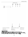
PANEL DESCRIPTIONS
Transmitter Panel
①Indicator of power input
④DIP switch
⑦Power input port
②Status of signal connection
⑤IR-TX port
⑧Ethernet port
③HDMI input
⑥Reset button
4 bits DIP Switch:
Use 4bits DIP switch to select 16 groups ID ( such as 0001,0010,0101 etc,)
Default TX unicast IP address is 192.168.168.55 , it can be configured from webpage.
TX Group IP address: 239.168.168.xx, (xx is the value of bits[2:0])
3
Operating Instructions
Receiver Panel
①Indicator of power input
④DIP switch
⑦Power input port
4 bits DIP Switch:
②Status of signal connection
⑤IR-RX port
⑧Ethernet port
③HDMI Output
⑥Reset button
Use 4bits DIP switch to select 16 group ID(such as 0001,0010,0101 etc,)
Default RX unicast IP address is 192.168.168.56, it can be configured from webpage.
RX Group IP address: 239.168.168. XXX (XXX is the value of bits[2:0])
4
Operating Instructions
User should configure the DIP switch within 10 seconds, firmware should reset the
system 20 second after detecting the first change of DIP switch, and latch the new
DIP switch value after reset.
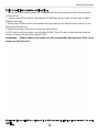
Point to point configuration:
1. Connect one HDMI Cable between the HDMI output port of source device and the HDMI input port of
Transmitter unit
2. Connect one HDMI Cable between the HDMI input port of display and the HDMI output port of Receiver
unit.
3. Connect one UTP Cat5e or better cables between the RJ45 port of Transmitter unit and RJ45 port of
Receiver unit.
4. Connect 5V DC power supplies to both Transmitter unit and Receiver unit.
5. Power on the output device first and the source second.
Important: Please make sure power on the transmitter and receiver first , then
power on the source !
Transmitter
Receiver
5
Operating Instructions
Point to multicast network configuration:
1. Connect one HDMI Cable between the HDMI output port of source device and the HDMI input port of
Transmitter unit
1. . Connect one CAT5e or better cable between the RJ45 port of transmitter and input port of Gigabit
Ethernet switch hub.
3. Connect one CAT5e or better cable between the output port of each Gigabit Ethernet switch hub and
RJ45 port of Receiver unit.
5. Power on the output device first and then the source device.
6. If DIP switch at the transmitter is set up: Group ID:0001, then DIP switch at each receiver should be
set up as same as the transmitter: Group ID:0001
Important: Please make sure power on the transmitter and receiver first , then
power on the source !
Modify the TX and all RX for a different IP & MAC address in LAN (local area network)to avoid
conflict.
6
Operating Instructions
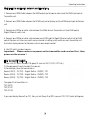
Multipoint to multipoint network configuration:
1. Connect one HDMI Cable between the HDMI output port of source device and the HDMI input port of
Transmitter unit.
2. Connect one HDMI Cable between the HDMI input port of display and the HDMI output port of Receiver
unit.
3. Connect one CAT5e or better cable between the RJ45 of each Transmitter unit and RJ45 port of
Gigabit Ethernet switch hub.
4. Connect one CAT5e or better cable between each RJ45 port of Gigabit Ethernet switch hub to RJ45
port of Receiver unit. User can select source channel by setting up dip switch on each transmitter unit.
And select display devices for Receiver units via one remote control.
5. Use DIP switch to select sources .
Important: Please make sure power on the transmitter and receiver first , then
power on the source !
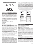
How to use DIP switch:
1).Use 4-bit DIP switch to select 16 group ID (such as 0001, 0010, 0101 etc.)
2).Change group ID easily to select the sources.
3).For example, when the connection is :
Source( DVD1) - TX (TX1) - Gigabit Switch - RX(RX1)- TV1
Source (DVD2) - TX (TX2) - Gigabit Switch - RX(RX2)- TV2
Source (DVD3) - TX (TX3) - Gigabit Switch - RX(RX3)- TV3
The group ID of transmitters is :
TX1 (0001)
TX2 (0101)
TX3 (0100)
If you need display Source2 on TV1, then just set Group ID of RX1 same as TX2: 0101 (refer to Diagram).
7
Operating Instructions
No need power adapter for TX & RX when connecting with POE Switch.
……
……
Modify all TX and all RX for a different IP & MAC address in LAN (local area network)to avoid
conflict.
8
Operating Instructions
Setup HDMI TX and HDMI RX
A HTTP server is embedded in each TX and RX. you can setup IP address for HDMI extender via web
browser.
The default IP address of the TX is 192.168.168.55, MAC address is: 00:0b:78:00:60:01.
The default IP address of the RX is 192.168.168.56, MAC address is: 00:0b:78:00:60:02.
Step 1: Assign the PC (or laptop) IP address on the computer : “Control Panel” →” Network
Connections”→“Local Area Connections Status”→“Properties”→“Internet Protocol (TCP/IP)”, Type the IP
address field with 192.168.168.11 (0-255) and Subnet mask with 255.255.255.0. After that press OK
to save the configuration.
Note: The IP address of PC should be different from the IP address of TX and RX.
Step 2: Use an Ethernet Cable to connect the PC (or laptop) and the extender. the power LED for the
extender is red and the status LED becomes green.
Step 3: please Ping the connected device through the sequence on computer: “Start”→ “Run”→ input
“CMD”→ input “ping 192.168.168.55” for TX or input “ping 192.168.168.56” for RX, you will receive
the reply if the connection is established.
Step 4: Login in IE :192.168.168.55 (default IP for TX) or 192.168.168.56(default IP for RX), You can
setup IP address, subnet mask, gateway, and MAC address for the TX and RX.
Please set IP address for each TX and each RX, IP:192.168.168.XX (XX:1-255. all IP address for TX and
RX must be different .
Please set MAC address for TX and RX, MAC:00:0b:78:XX:XX-XX (XX:01-FF), The MAC address for each
TX and each RX must be different .
Step 5: After click “Apply” button, the green LED light on the device will go out, you have successfully set
IP address for TX and RX now.
Note: if you need to restore the device to it’s factory default settings, please power on the device, the red
light becomes lighting, waiting about 10 seconds, the green LED light starts working, at this time to press
the reset button about 5-10 seconds, then the green light will go out, you have successfully restored IP
address to factory IP address now.
9
Operating Instructions
PRODUCT SERVICE
1) Damage requiring service: The unit should be serviced by qualified service personnel if:
(a)The DC power supply cord or AC adaptor has been damaged;
(b)Objects or liquids have gotten into the unit;
(c)The unit has been exposed to rain;
(d)The unit does not operate normally or exhibits a marked change in performance;
(e)The unit has been dropped or the cabinet damaged.
2) Servicing Personnel: Do not attempt to service the unit beyond that described in these operating
instructions. Refer all other servicing to authorized servicing personnel.
3) Replacement parts: When parts need replacing ensure the servicer uses parts specified by the
manufacturer or parts that have the same characteristics as the original parts. Unauthorized substitutes
may result in fire, electric shock, or other hazards.
4) Safety check: After repairs or service, ask the servicer to perform safety checks to confirm that the
unit is in proper working condition.
WARRANTY
If your product does not work properly because of a defect in materials or workmanship, our Company
(referred to as "the warrantor" ) will, for the length of the period indicated as below, (Parts(2)Year,
Labor(90) Days) which starts with the date of original purchase ("Limited Warranty period"), at its option
either(a) repair your product with new or refurbished parts, or (b) replace it with a new of a refurbished
product. The decision to repair or replace will be made by the warrantor.
During the "Labor" Limited Warranty period there will be no charge for labor.
During the "Parts" warranty period, there will be no charge for parts. You must mail-in your product
during the warranty period. This Limited Warranty is extended only to the original purchaser and only
covers product purchased as new. A purchase receipt or other proof of original purchase date is required
for Limited Warranty service.
MAIL-IN SERVICE
When shipping the unit carefully pack and send it prepaid, adequately insured and preferably in the
original carton. Include a letter detailing the complaint and provide a day time phone and/or email
address where you can be reached.
10
Operating Instructions
LIMITED WARRANTY LIMITS AND EXCLUSIONS
1) This Limited Warranty ONLY COVERS failures due to defects in materials or workmanship, and DOES
NOT COVER normal wear and tear or cosmetic damage.
The Limited Warranty ALSO DOES NOT COVER damages which occurred in shipment,
or failures which are caused by products not supplied by warrantor, or failures which result from
accidents, misuse, abuse, neglect, mishandling, misapplication, alteration, faulty installation, set-up
adjustments, misadjustment of consumer controls, improper maintenance, power line surge, lightning
damage, modification, or service by anyone other than a Factory Service center or other Authorized
Servicer, or damage that is attributable to acts of God.
2) THERE ARE NO EXPRESS WARRANTIES EXCEPT AS LISTED UNDER "LIMITED WARRANTY COVERAGE".
THE WARRANTOR IS NOT LIABLE FOR INCIDENTAL OR CONSEQUENTIAL DAMAGES RESULTING FROM
THE USE OF THIS PRODUCT, OR ARISING OUT OF ANY BREACH OF THIS WARRNTY. (As examples, this
excludes damages for lost time, cost of having someone remove or re-install an installed unit if
applicable,
travel to and from the service, loss of or damage to media or images, data or other recorded content. The
items listed are not exclusive, but are for illustration only.)
3) PARTS AND SERVICE, WHICH ARE NOT COVERED BY THIS LIMITED WARRANTY, ARE
YOUR RESPONSIBILITY.
11