1
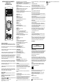
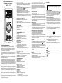
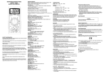
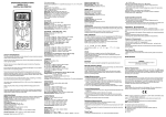
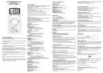
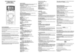
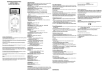
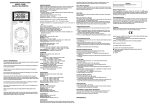
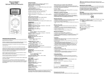
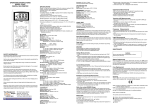
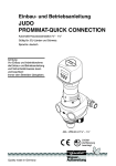
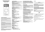
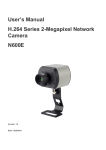
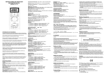
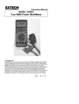
OPERATING INSTRUCTIONS
MODEL 2703C
DIGITAL MULTIMETER
SPECIFICATIONS
Display: 3½ digit liquid crystal display (LCD) with a maximum reading of 1999.
Polarity: Automatic, positive implied, negative polarity indication.
Overrange: (OL) or (-OL) is displayed.
Zero: Automatic.
Low battery indication: The " " is displayed when the battery voltage drops
below the operating level.
Measurement rate: 2.5 times per second, nominal.
Auto power off: Approx. 25 minutes.
Operating environment: 0℃to 50℃at < 70% relative humidity.
Storage temperature: -20℃to 60℃, 0 to 80% relative humidity.
Accuracy: Stated accuracy at 23 ℃±5℃, < 75% relative humidity.
Temperature Coefficient: 0.1 x (specified accuracy) per ℃. (℃to 18℃, 28℃ to
2703C
V
V
50℃).
Altitude: 6561.7 feet (2000m).
Power: Single standard 9-volt battery, NEDA 1604, JIS 006P, IEC 6F22.
Battery life: 200 hours typical with carbon-zinc.
Dimensions: 165mm (H) x78mm (W) x42.5mm (D).
Weight: Approx. 10.0 oz.(285g) including holster.
Accessories: One set test leads, one spare fuse, 9V battery (installed), and
Operating Instructions.
DC VOLTS
Ranges: 2V, 20V, 200V, 1000V
Resolution: 1mV
Accuracy: ± ( 1.2% rdg + 1 dgt)
Input impedance: 10MΩ
Overload protection: 1000VDC or 750VAC rms
A
AC VOLTS
BATT 1.5V
mA
COM
V
10A
(50Hz - 500Hz)
Ranges:200V, 750V
Resolution: 0.1V
Accuracy: ± ( 2.0% rdg + 5 dgts) on 200V range
± ( 2.0% rdg + 10 dgts) on 750V range
Input impedance: 10MΩ
Overload protection: 1000VDC or 750VAC rms
DC CURRENT
SAFETY INFORMATION
The following safety information must be observed to ensure maximum personal
safety during the operation at this meter:
Use the meter only as specified in this manual or the protection provided by the
meter might be impaired.
Ranges: 2mA, 20mA, 200mA, 10A
Resolution: 1uA
Accuracy: ± (1.5% rdg + 1 dgts) on 2mA to 200mA ranges
± (3.0% rdg + 3 dgts) on 10A range
Input protection: 0.5A/500V fast blow ceramic fuse on mA input
10A/600V fast blow ceramic fuse on mA input
10A input:10A for 60 seconds maximum followed by a
10 minutes cooling period.
RESISTANCE
Test the meter on a known voltage before using it to determine if hazardous
voltage is present.
Do not use the meter if the meter or test leads look damaged, or if you suspect
that the meter is not operating properly.
Never ground yourself when taking electrical measurements. Do not touch
exposed metal pipes, outlets, fixtures, etc., which might be at ground potential.
Keep your body isolated from ground by using dry clothing, rubber shoes, rubber
mats, or any approved insulating material.
Turn off power to the circuit under test before cutting, unsoldering, or breaking
the circuit. Small amounts of current can be dangerous.
Use caution when working above 60V dc or 30V ac rms. Such voltages pose a
shock hazard.
When Using the probes, keep your fingers behind the finger guards on the
probes.
Measuring voltage which exceeds the limits of the multimeter may damage the
meter and expose the operator to a shock hazard. Always recognize the meter
voltage limits as stated on the front of the meter.
Ranges: 200Ω, 2k, 20k, 200k, 20MΩ
Resolution: 0.1Ω
Accuracy:
± (1.5% rdg + 4 dgts) on 200 Ωto 200kΩranges
± (3.0% rdg + 5 dgts) on 20MΩrange
Open circuit volts: 0.3Vdc typical, (3.0Vdc on 200Ωrange)
Overload protection: 500VDC or AC rms
CONTINUITY
Audible indication: Less than 100Ω
Response time: 100ms
Overload protection: 500VDC or AC rms
DIODE TEST
Test current: Approx. 1.0mA
Accuracy: ±(3.0% rdg + 3dgts)
Open circuit volts: 3.0Vdc typical
Overload protection: 500VDC or AC rms
BATTERY TEST
Ranges: 1.5V, 9V
Resolution: 1mV, 10mV
Accuracy: ±(3.5% rdg + 2 dgts)
Loaded current:150mA typical for 1.5V range, 5mA
typical for 9V range
Overload protection: 500V DC or AC rms on 9V range,
0.5A/500V fast blow ceramic fuse on 1.5V range.
OPERATION
Fuse Replacement
Before taking any measurements, read the Safety Information Section. Always
examine the instrument for damage, contamination (excessive dirt, grease, etc.)
and defects. Examine the test leads for cracked or frayed insulation. If any
abnormal conditions exist do not attempt to make any measurements.
If no current measurements are possible. check for a blown overload protection
fuse. For access to fuses, remove the three screws from the back of the meter
and lift off the front case. Replace F1 only with the original type 0.5A/500V, fast
acting ceramic fuse, 6.35x32mm .
Replace F2 only with the original type 10A/600V, fast acting ceramic fuse,
6.35x25.4mm.
Voltage Measurements
1.Connect the red test lead to ”VΩ” jack and the black test lead to the ”COM”
jack.
2.Set the Function/Range switch to the desired voltage type (AC or DC) and
range. If magnitude of voltage is not known, set switch to the highest range
and reduce until a satisfactory reading is obtained.
3.Connect the test leads to the device or circuit being measured.
4. For dc, a (-) sign is displayed for negative polarity; positive polarity is implied.
Current Measurements
Cleaning
Wipe the case with a damp cloth and mild detergent. Do not use abrosives or
solvents. Dirt or moisture in the terminals can affect readings.
1.Connect the red test lead to the (uA, mA or 10A) jack and the black test lead to
the "COM" jack.
2.Set the Function/Range switch to the DC or AC ranges.
3.Remove power from the circuit under test and open the normal circuit path
where the measurement is to be taken. Connect the meter in series with the
circuit.
4.Apply power and read the value from the display.
Safety: Conforms to IEC61010-1 (EN61010-1), CATII 1000V, CATIII 600V, Class
II, Pollution degree 2 Indoor use.
CATII: Is for measurements performed on circuits directly connected to the
low-voltage installation.
CAT III: Is for measurements performed in the building installation.
Resistance and Continuity Measurements
The symbols used on this instrument are:
1.Set the Function/Range switch to the desired resistance range or continuity
position.
2.Remove power from the equipment under test.
3.Connect the red test lead to the “ VΩ” jack and the black test lead to
the ”C O M ” jack.
4.Touch the probes to the test points. In ohms, the value indicated in the display
is the measured value of resistance. In continuity test, the beeper sounds
continuously, if the resistance is less than 100Ω.
Diode Tests
1.Connect the red test lead to the “ VΩ” jack and the black test lead to
the ”C O M ” jack.
2.Set the Function/Range switch to the “ “ position.
3.Turn off power to the circuit under test. External voltage across the
components causes invalid readings.
4.Touch probes to the diode. A forward-voltage drop is about 0.6V (typical for a
silicon diode).
5.Reverse probes. If the diode is good, “OL” is displayed. If the diode is shorted,
“000” or another number is displayed.
6. If the diode is open, “OL” is displayed in both directions.
Battery Test
1. Connect the red test lead to the (mA/BATT 1.5V) jack and the black test lead to
the "COM" jack.
2. Set the Function/Range switch to the desired 1.5V battery test range.
3. Connect the test leads to the 1.5Vdc battery under test. Normally, a good
1.5Vdc battery will read above 1.25Vdc. Consult the battery manufacturer for
complete battery specifications to determine actual battery life remaining and
condition of battery.
MAINTENANCE
WARNING
Remove test leads before changing battery or fuse or performing
any servicing.
Battery Replacement
Power is supplied by a 9 volt battery. (NEDA 1604, IEC 6F22). The " " appears
on the LCD display when replacement is needed. To replace the battery, remove
the three screws from the back of the meter and lift off the front case. Remove
the battery from case bottom.
EMC: Conforms to EN61326.
Caution, refer to accompanying documents
Equipment protected throughout by Double insulation (Class II)
Alternating current
Direct current
Ground
INSTRUCCIONES DE FUNCIONAMIENTO
MODELO 2703C
MULTIMETRO DIGITAL
VOLTIOS de CD
Rangos: 2V, 20V, 200V, 1000V
Resolución : 1mV
Precisión: ± (0.5% lectura + 1dgt)
Impedancia de entrada: 10MΩ
Protección de sobrecarga:1000VCD o 750VCA rms
2703C
V
V
A
BATT 1.5V
mA
COM
Entorno operativo: 0° a 50° a <70% de humedad relativa.
Temperatura de almacenamiento: -20° a 60°, de 0 a 80% de humedad relativa.
Precisión: Dicho de precisión a 23° ± 5°, <75% de humedad relativa.
Coeficiente de temperatura: 0.1 x (exactitud especificada) por °C. (°C a 18°C,
28°C a 50°C).
Altitud: 6561,7 pies (2000m).
Potencia: El único estándar de la batería de 9 voltios, NEDA 1604, JIS 006P,
IEC 6F22.
La duración de la batería: 200 horas típico con carbono-zinc.
Dimensiones: 165mm (H) x78mm (W) x42.5mm (D).
Peso: aprox. 10,0 oz (285g) incluyendo funda.
Accesorios: Un conjunto conductores de prueba, un fusible de repuesto, batería
de 9V (instalada), y Manual de instrucciones.
V
10A
INFORMACION DE SEGURIDAD
La siguiente información relativa a la seguridad deben ser observadas para
garantizar la máxima seguridad personal durante la operación de este metro:
Utilice el medidor sólo como se especifica en este manual o la protección prevista
en el metro podría verse afectada.
Pruebe de que el medidor en un voltaje conocido antes de usarlo para determinar
si está presente la tensión peligrosos.
No utilice el medidor si el medidor o los conductores de prueba parecen dañados,
o si sospecha que el medidor no está funcionando correctamente.
Nunca esté conectado a tierra cuando este tomando mediciones eléctricas. No
toque las tuberías de metal expuesto, puntos de venta, accesorios, etc, que
podrán estar conectados a tierra. Mantenga su cuerpo aislados de tierra
mediante el uso de ropa seca, zapatos de goma, alfombras de caucho, o
cualquier material aislante aprobado.
Apague la potencia al circuito bajo prueba antes de cortar, quitar soldadura, o
romper el circuito. Pequeñas cantidades de corriente pueden ser peligrosas.
Tenga cuidado cuando se trabaja con mas de 60V de CD o 30 V CA rms. Esas
tensiones plantean un peligro de choque.
Al utilizar las sondas, mantenga los dedos detrás del dedo de la mano de los
guardias de las sondas.
La medición de tensión que excede los límites del multímetro puede dañar el
medidor y el operador se puede de exponer a un peligro de choque. Siempre
reconozca los límites de voltaje en el frente del medidor.
ESPECIFICACIONES
Pantalla: 3 ½ dígitos, pantalla de cristal líquido (LCD) con un máximo de la
lectura de 1999.
Polaridad: Automática, positiva implícita, indicación de polaridad negativa.
Sobre Rango: (OC) o (-OC) aparece en pantalla.
Cero: Automático.
Indicación de batería baja: El " " aparece cuando el voltaje de la batería cae
por debajo del nivel de funcionamiento.
Tipo de Medición: 2,5 veces por segundo, nominal.
Apagado automático: aprox. 25 minutos.
VOLTIOS de AC (50Hz - 500Hz)
Rangos: 200V, 750V
Resolución : 0.1V
Precisión:
± (2.0% lectura +5dgts)
Impedancia de entrada: 10MΩ
Protección de sobrecarga: 1000VDC o 750VAC rms
CORRIENTE
Rangos: 2mA, 20mA, 200mA, 10A
Resolución : 1uA
Precisión CD: ± (1.5%rdg + 1dgts) en 2mA a 200mA
± (3.0%rdg + 3dgts) en 10A range
Entrada de protección: 0.5A/500V fusibles rápido de cerámica
10A/600V fusibles rápido de cerámica
Entrada de 10A: 10A máximo durante 60 segundos seguidos
Por 10 minutos en un período de enfriamiento
RESISTENCIA
Rangos: 200Ω, 2kΩ, 200kΩ, 20MΩ
Resolución : 0.1Ω
Precisión:
± (1.0% lectura + 4dgts) sobre 200Ωa 200kΩrangos
± (2.0% lectura + 5dgts) en la gama 20MΩ
Voltios de circuito abierto: 0.3Vdc (3.0Vdc gama de 200Ω)
Protección de sobrecarga: 500VCD o CA rms
CONTINUIDAD
Indicación audible: Menos de 100Ω
Tiempo de respuesta: 100ms
Protección de sobrecarga: 500VCD o CA rms
PRUEBA DE DIODO
Corriente de prueba: aprox. 1.0mA
Precisión: ± (1,5% lectura + 3dgts)
Voltios circuito abierto: 3.0Vdc típico
Protección de sobrecarga: 500VCD o CA rms
4. Para muestra polaridad negativa, un (-) se demuestra; polaridad positiva
es implicado.
Las mediciones de Corriente
1.Conecte el conductor rojo de prueba a la (tC, mA o 10A) jack y el
conductor negro de prueba a la "COM" jack.
2. Seleccione la Función / Rango para cambiar de los rangos de CD a CA.
3. Elimine el poder del circuito bajo prueba y abra el circuito normal de ruta
donde la medición es que se deben tomar. Conecte el medidor en serie con
el circuito.
4. Aplicar y poder leer el valor de la exhibición.
Mediciones de Resistencia y Continuidad
1. Seleccione la Función / Rango cambiar a la resistencia deseada gama.
2. Elimine el poder de los equipos bajo prueba.
3. Conecte el conductor rojo de prueba a la "V Ω" jack y el conductor negro
de prueba a la "COM" jack.
4. Toque las sondas a los puntos de prueba. En ohmios, el valor indicado en
la pantalla es el valor medido de la resistencia. En la continuidad de prueba,
el zumbador suena continuamente, si la resistencia es inferior a 100Ω.
Pruebas de Diodo
1.Conecte el conductor rojo de prueba a la "V Ω" jack y el conductor negro
de prueba a la "COM" jack.
2. Seleccione la Función / Rango a al posición de "(diode symbol)".
3. Elimine el poder de los equipos bajo prueba. Exteriores voltaje a través
de los componentes causas lecturas no válidas.
4. Toque las sondas al diodo. Una caída de tensión hacia adelante-es de
unos 0.6V (típico para un diodo de silicio).
5. Reverse sondas. Si el diodo es bueno, el "OL" se muestra. Si el diodo
está e n cortocircuito, "000" u otro número aparece en la pantalla.
6. Si el diodo está abierto, el "OL" se muestra en ambas direcciones.
7. Indicación audible: Menos de 0.03V.
Prueba de Batería
1. Conecte el conductor de prueba rojo a el (mA / BATT 1.5V) jack y el
conductor negro de prueba a el "COM" jack.
2. Establezca la Función / Rango por cambiando a la deseada gama de
1.5V.
3. Conecte los conductores de prueba a la batería de 1.5Vcd bajo prueba.
Normalmente, una buena batería de 1.5Vcd dará lectura sobre 1.25Vcd.
Consulte fabricante de la batería para determinar las especificaciones
reales de la vida de la batería restante y el estado de la batería.
MANTENIMIENTO
ADVERTENCIA
Eliminar conductores de prueba antes de cambiar la batería o
fusible o realización de cualquier servicio.
Reemplazo de baterías
La potencia es suministrada por una batería de 9 voltios. (NEDA 1604, IEC
6F22). El "(battery symbol)" aparece en pantalla, cuando el reemplazo es
necesario. Para sustituir la batería, quite los tres tornillos de la parte
posterior del medidor y el ascensor frente a la parte delantera caso.
Extraiga la batería caso de la parte inferior.
Prueba de Bateria
Rango: 1.5V, 9V
Resolución : 1mV, 10mV
Precisión: ± 3.5%rdg + 2dgts)
Carga de corriente: 150mA típico de 1.5V gama, 5mA
Gama típica de 9V
Protección de sobrecarga: 500VCD o CA rms gama de 9V,
0.5A/500V fusible rápido de cerámica de 1.5V gama.
OPERACIÓN
Antes de tomar cualquier medida, lea la sección de Información sobre
Seguridad. Siempre examine el instrumento para para daños, la
contaminación (exceso de suciedad, grasa, etc) y defectos. Examine los
conductores de prueba para agrietados o rotos aislamiento. Si alguna de la
condiciones existe no intente realizar las mediciones.
Luz de Fondo
Oprime el botón para activar la luz de fondo por aproximadamente 60
segundos.
Las mediciones de voltaje
1.Conect e el conductor rojo de prueba a la "V Ω" jack y el conductor negro
de prueba a la "COM" jack.
2. Seleccione la Función / Rango de cambio al tipo deseado de voltaje (CA
o CD) y la variedad. Si la magnitud de la tensión no es conocida,
sistemáticamente camb ie a una escala mayor y reduzca el rango a una
manera satisfactoria hasta que se obtenga la lectura adecuada.
3. Conecte los conductores de prueba al dispositivo o circuito con que se
mide.
Reemplazo de fusibles
Si las mediciones de corriente no son posibles. Revise por el fusible de
protección de sobrecarga que no este quemado. Para el acceso a los fusibles,
quite los tres tornillos de la parte posterior del medidor y el ascensor frente a la
parte delantera caso. Sustituir F1 sólo con el tipo original 0.5A/500V, actuando
rápida de fusibles de cerámica, 6.35x32mm Sustitúyase F2 sólo con el original
10A/600V tipo, que actúan rápido de fusibles de cerámica, 6.35x25.4mm.
Limpieza
Limpie el caso con un paño húmedo y detergente suave. No utilice
productos abrasivos o disolventes. La humedad o la suciedad en los
terminales pueden afectar a las lecturas.
Seguridad: Se ajusta a IEC61010 -1 (EN61010-1), CATII 1000V, CATIII
600 V, clase II, grado de contaminación 2 Salas de uso.
CATII: Es para las mediciones realizadas en los circuitos conectados
directamente a la instalación de baja tensión
CAT III: Es para las mediciones realizadas en la construcción de la
instalación.
EMC: Se ajusta a EN61326.
The symbols used on this instrument are:
Precaución, refiérase a los documentos que la acompañan
Equipo protegido en todo momento por doble aislamiento (clase II)
Corriente alterna
Corriente
Ground
Manuel d’utilisation
Modèle 2703C
Multimètre Numérique 2000 points
SPECIFICATIONS
Affichage: 3½ digit (LCD) avec un affichage de 1999 maximum
Polarité: Automatique, avec indication du signe moins.
Dépassement: (OL) ou (-OL) est affiché.
Zéro: Automatique.
Indication de pile usée: le symbole " "est affiché lorsque la pile est usée et
qu’il faut la remplacée.
Cadence de mesure: 2.5 fois/s (typique)
Arrêt automatique: après environ 25 minutes.
Température de fonctionnement: 0℃ à 50℃ avec HR < 70%.
Température de stockage: -20℃ à 60℃, HR de 0 à 80%.
Précision: donnée à 23℃ ±5℃, HR < 75%.
Coefficient de température: 0.1 x (précision) par ℃. (℃ < 18℃, et de 28℃ à
2703C
V
V
50℃).
Altitude: utilisation jusqu’à 2000m.
Alimentation: pile 9 V t ype NEDA 1604, JIS 006P, IEC 6F22.
Autonomie: 200 heures typique.
Dimensions: 165mm (H) x 78mm (W) x 42.5mm (D).
Masse: environ 285g avec gaine
Accessoires: jeu de cordons, fusible de rechange, pile (9V) installée, manuel.
Remplacement des fusibles
MISE EN OEUVRE
Avant toute mesure, assurez-vous d’avoir pris connaissance des Prescriptions
de Sécurité. Toujours vérifier que l’appareil et ses cordons ne sont pas
endommagés. Si vous avez le moindre doute, ne pas effectuer de mesure.
Mesures de tension
1. Brancher le cordon rouge à la borne ”VΩ” et le cordon noir à la borne ”COM”.
2. Positionner le commutateur sur la gamme appropriée en DC ou AC. Toujours
commencer par la gamme la plus élevée si vous ne connaissez pas la valeur à
mesurer.
3. Brancher les cordons sur votre application.
4. Lire le résultat sur l’afficheur LCD. La polarité est indiquée avec le signe (-) en
DC
A
TENSIONS AC (50Hz - 500Hz)
BATT 1.5V
mA
COM
V
10A
Gammes: 200V, 750V
Résolution: 0.1V
Précision: ± ( 2.0% + 5 dgts) sur 200V
± ( 2.0% rdg + 10 dgts) sur 750V
Impédance d’entrée: 10MΩ
Protection: 1000VDC ou 750VAC eff.
COURANTS DC
PRESCRIPTIONS DE SECURITE
Les prescriptions de sécurité ci dessous sont à suivre scrupuleusement afin de
garantir la sécurité de l’utilisateur:
N’utiliser votre appareil que dans le domaine d’utilisation défini dans ce manuel.
Dans le cas contraire les protections pourraient être endommagées.
Toujours tester votre appareil sur une tension connue avant de l’utiliser pour une
mesure de tension.
Ne pas utiliser votre appareil o uses cordons vous semblent endommagés.
Ne jamais vous mettre à la terre lorsque vous faites des mesures de tension. Ne
jamais toucher des parties métalliques qui pourraient être reliées à la terre lors
d’une mesure. Dans la mesure du possible, isolez-vous de la terre par des
chaussures, vêtements ou gants appropriés.
Pensez à couper le courant avant d’ouvrir un circuit ou d’intervenir sur celui-ci.
Même un faible potentiel peut être dangereux.
Prenez toutes les précautions nécessaires lorsque vous intervenez sur des
tensions supérieures à 60V DC ou 30V AC eff.
Lorsque vous utilisez des pointes de touche, ne jamais mettre les doigts au delà
des anneaux de garde.
Mesurer des tensions ou grandeurs au delà des limites de l’appareil peut
endommager les protections, endommager votre appareil et mettre en danger la
sécurité de l’utilisateur. Assurez vous de connaître les limites de votre appareil,
avant utilisation.
Gammes: 2mA, 20mA, 200mA, 10A
Résolution: 1uA
Précision: ± (1.5% + 1 dgts) sur 2mA et 200mA
± (3.0% + 3 dgts) sur la gamme 10A
Protection: fusible rapide0.5A/500V sur les gammes mA
Fusible rapide 10A/600V sur la gamme 10A
Entrée 10A: 10A pendant 60 secondes maximum suivi d’une période sans
courant de 10minutes minimum
RESISTANCE
Gammes: 200Ω, 2k, 20k, 200k, 20MΩ
Résolution: 0.1Ω
Précision:
± (1.5% + 4 dgts) jusqu’à 200kΩ
± (3.0% + 5 dgts) sur gamme 20MΩ
Tension en circuit ouvert: 0.3Vdc typique, (3.0V sur gamme 200Ω)
Protection: 500VDC ou AC eff.
TEST DIODE
Courant de test: environ 1.0mA
Précision: ±(3.0% + 3dgts)
Tension en circuit ouvert: 3.0V typique
Protection: 500VDC ou AC eff.
TEST PILE
Gammes: 1.5V, 9V
Résolution: 1mV, 10mV
Précision: ±(3.5% + 2 dgts)
Courant de charge: 150mA typique pour la gamme1.5V, 5mA
typique pour la gamme 9V
Protection: 500VDC ou AC eff. Sur gamme 9V,
Fusible F0.5A/500V sur gamme1.5V.
Nettoyer périodiquement avec un chiffon doux et humide. Ne pas utiliser de
solvants. Saleté et/ou humidité au niveau des douilles peuvent perturber les
mesures et donner des indications fausses.
1. Brancher le cordon rouge à la borne (µA, mA ou 10A) et le cordon noir à la
borne ”COM”.
2. Positionner le commutateur sur la gamme appropriée en DC ou AC.
3. Assurez-vous que le circuit à mesurer est hors tension et branchez vos
cordons en série dans ce circuit.
4. Mettre sous tension et lire le courant sur l’afficheur LCD
Sécurité: IEC61010-1 (EN61010-1), CATII 1000V, CATIII 600V, Class II, Degré
de pollution 2, utilisation à l’intérieur.
CATII / CAT III : se reporter aux normes pour la définition des catégories
d’installation
Mesures de résistance et continuité
Symboles utilisés sur l’appareil:
1. Positionner le commutateur rotatif sur la gamme appropriée de résistance ou
continuité.
2. Assurez-vous que le dispositif à mesurer soit hors tension.
3. Brancher le cordon rouge à la borne ”VΩ” et le cordon noir à la borne ”COM”.
4. Branchez les cordons à votre application ou tester par contact avec les
pointes de touche. En test de continuité, le buzzer est actif pour R<100 ohms..
Test Diode
1. Brancher le cordon rouge à la borne ”VΩ” et le cordon noir à la borne ”COM”.
2. Positionner le commutateur sur “ “ .
3. Assurez-vous que le dispositif à mesurer soit hors tension, afin de ne pas
fausser la mesure.
4. Tester la diode à l’aide des pointes de touché: le sens passant d’une diode
silicium fait apparaitre une tension de 0.6V (typique)
5. Une diode ouverte ou sens bloqué se traduira par un affichage “OL”. Une
diode en court-circuit se traduira par un affichage “000” ou proche de 0.
6. Remarque: une diode ouverte donne un affichage “OL” dans les 2 sens
Test piles
1. Brancher le cordon rouge à la borne mA/1.5V et le cordon noir à la
borne ”COM”.
2. Positionner le commutateur sur test pile 1.5V
3. Brancher les cordons aux bornes de la pile et lire la tension. Normalement une
pile correcte donne une tension > 1.25V (vérifier avec votre fabricant de piles)
MAINTENANCE
ATTENTION - DANGER
Il est impératif de débrancher les cordons avant toute opération de
maintenance – Risque de choc électrique.
CONTINUITE
Indication sonore: pour R< 100Ω
Temps de réponse: 100ms
Protection: 500VDC ou AC eff.
Nettoyage
Mesures de courant
TENSIONS DC
Gammes: 2V, 20V, 200V, 1000V
Résolution: 1mV
Précision: ± ( 1.2% + 1 dgt)
Impédance d’entrée: 10MΩ
Protection: 1000VDC ou 750VAC eff.
Si les mesures de courant ne fonctionnent pas, il faut vérifier l’état des fusibles
qui assurent la protection de votre multimètre. Assurez-vous d’avoir débranché
les cordons. Dévisser le fond de boitier et vérifier les fusibles :
F1 0.5A/500V, type céramique F (rapide), 6.35x32mm.
F2 10A/600V, type céramique F (rapide), 6.35x25.4mm.
Attention : Ne remplacer les fusibles qu’avec le même type.
Remplacement de la pile
Votre multimètre utilise une pile 9V. (NEDA 1604, IEC 6F22). Lorsque le symbole
" " apparait à l’affichage il faut remplacer la pile. Assurez-vous d’avoir
débranché les cordons. Dévisser le fond de boitier et remplacer la pile. Revisser
le fond de boitier.
EMI: selon EN61326.
Attention – Danger: se référer au manuel
Double isolement (Classe II)
Courant alternatif
Courant continu
Terre
BEDIENUNGSANLEITUNG
DIGITAL-MULTIMETER
MODELL 2703C
TECHNISCHE DATEN
FUNKTIONSBESCHREIBUNG / BETRIEB
Display: 3½ -stellige Flüssigkristallanzeige (LCD) mit max. 1999 Zählimpulsen.
Polarität: Automatisch, positive Polarität implizit, negative wird angezeigt.
Bereichsüberschreitung: Anzeige von (OL) oder ( -OL).
Null: Automatisch
Indikator bei schwacher Batteriespannung : Sinkt die Batteriespannung unter
das Betriebsniveau, wird das Symbol
angezeigt.
Messrate: Nennwert 2,5 Mal pro Sekunde.
Automatische Abschaltung: nach ca. 30 Minuten Inaktivität
Betriebsumgebung: 0℃ bis 50℃ bei einer relativen Feuchtigkeit < 70%.
Bevor Sie Messungen durchführen, lesen Sie bitte den Abschnitt Sicherheitsinformationen. Überprüfen Sie das Instrument stets auf Beschädigungen,
Schmutz (übermäßige Verschmutzungen, Fett usw.) und Defekte. Überprüfen
Sie die Isolierung der Messleitungen auf Risse oder Abnutzungserscheinungen.
Das Messgerät auf keinen Fall verwenden, wenn irgendwelche ungewöhnliche
Bedingungen vorliegen.
Lagertemperatur: -20℃ bis 60℃, 0 bis 80% relative Feuchtigkeit.
Genauigkeit: Angaben gelten für 23℃ ±5℃ und einer relativen Feuchte < 75%.
Temperaturkoeffizient: 0,1 x (spezifizierte Genauigkeit) pro ℃. (℃ bis 18℃, 28
2703C
V
V
℃ bis 50℃).
Maximale Höhenlage für den Betrieb: 2000 m.
Stromversorgung: 9-Volt-Bockbatterie, Typ NEDA 1604, JIS 006P, IEC 6F22.
Batterielebensdauer: 150 Stunden typisch für Kohle-Zink.
Abmessungen: 165 mm (H) x 78 mm (B) x 42,5 mm (T).
Gewicht: ca. 285 g inkl. Holster.
Zubehör: 1 Satz Prüfkabel, 1 Stk. Ersatzsicherung, 9 V-Batterie (eingelegt) und
Bedienungsanleitung.
GLEICHSPANNUNG
Bereiche: 2V; 20V; 200V; 1000 V.
Auflösung: 1mV
Genauigkeit: ± (1,2% des Messwerts + 1 Stelle)
Eingangsimpedanz: 10MΩ
Überlastschutz: 1000 VDC oder 750 VAC Effektivwert
A
mA
COM
V
10A
SICHERHEITSINFORMATIONEN
Um ein Maximum an persönlicher Sicherheit beim Betrieb dieses Multimeters zu
gewährleisten, bitte unbedingt folgende Sicherheitshinweise beachten:
Das Gerät nur nach der in dieser Bedienungsanleitung angegebenen Spezifikation verwenden. Ansonsten können die im Messinstrument vorhandenen
Schutzmechanismen außer Kraft gesetzt sein.
Testen Sie das Multimeter zuerst mit einer bekannten Spannung, bevor Sie es
dafür verwenden, das Vorhandensein von gefährlichen Spannungen zu überprüfen.
Das Multimeter nicht verwenden, wenn das Instrument oder die Prüfkabel Beschädigungen aufweisen oder wenn Sie den Eindruck haben, dass das Gerät
nicht ordnungsgemäß funktioniert.
Bei Durchführung elektrischer Messungen keine Erdung zum eigenen Körper
herstellen. Niemals offen liegende, blanke Kabel, Ausgänge, Anschlüsse, Vorrichtungen, Halterungen berühren, um jeglichen Kontakt mit Erdpotential zu vermeiden. Sorgen Sie dafür, dass Ihr Körper von der Erde isoliert bleibt, indem Sie
trockene Kleidung, Gummischuhe, Gummimatten oder anderes zugelassenes
Isolierungsmaterial verwenden.
Schalten Sie den zu prüfenden Schaltkreis zuerst stromlos, bevor Sie ihn trennen,
ablöten oder unterbrechen. Auch geringe Strommengen können gefährlich sein.
Seien Sie besonders vorsichtig, wenn Sie mit Spannungen arbeiten, die über 60V
Gleichstrom oder 30 V Wechselstrom Effektivwert (rms) liegen. Spannungen in
dieser Höhe lösen elektrische Schläge aus.
Beim Umgang mit den Prüfspitzen die Finger bitte stets hinter der Abschirmung
des Isoliergriffs halten.
Die Messung von Spannungen, die die Grenzwerte des Multimeters übersteigen,
kann das Gerät beschädigen und den Bediener der Gefahr eines Stromschlags
aussetzen. Beachten Sie bitte stets die auf der Vorderseite des Geräts
angegebenen Spannungsgrenzwerte.
1. Die rote Messleitung an die Buchse „VΩ” und die schwarze Messleitung an die
Buchse „COM“ anschließen.
2. Den Funktions-/Bereichswahlschalter auf den gewünschten Spannungstyp
(AC oder DC) und den Bereich einstellen. Ist die Größe der Spannung nicht
bekannt, den Schalter auf den größten Bereich einstellen und dann reduzieren,
bis ein zufriedenstellender Messwert erreicht ist.
3. Die Messleitungen an das zu messende Gerät oder den zu messenden Schaltkreis anschließen.
4. Für Gleichspannung (DC) wird für negative Polarität das Zeichen (-) angezeigt;
positive Polarität ist implizit.
Strommessungen
1. Die rote Messleitung an die Buchse „uA, mA oder 10A ” und die schwarze
Messleitung an die Buchse „COM“ anschließen.
2. Den Funktions-/Bereichswahlschalter auf den Bereich AC oder DC einstellen.
3. Stromversorgung des zu messenden Schaltkreises abschalten und die
normale Leiterbahn öffnen, an der die Messung vorgenommen werden soll.
Das Multimeter mit dem Schaltkreis in Reihe schalten.
4. Den Strom einschalten und den Wert auf dem Display ablesen.
Bereiche: 200V, 750V
Auflösung: 0,1V
Genauigkeit:
± ( 2% des Messwerts + 5 Stellen) im 200V-Bereich
± ( 2,0% des Messwerts + 10 Stellen) im 750V-Bereich
Eingangsimpedanz: 10MΩ
Überlastschutz: 1000 VDC oder 750 VAC Effektivwert
GLEICHSTROM
Diodentests
Bereiche: 2mA, 20mA, 200mA, 10A
Auflösung: 1µA
Genauigkeit Gleichstrom:
± ( 1,5% des Messwerts + 1 Stelle) in den Bereichen 2mA bis 200mA
± ( 3,0% des Messwerts + 3 Stellen) im 10 A-Bereich
Eingangsschutz: Flinke Keramiksicherung 0,5 A / 500 V
Flinke Keramiksicherung 10 A / 600 V
10 A-Eingang: 10 A für 60 Sekunden Maximum gefolgt von einer
Abkühlphase von 10 Minuten
1. Die rote Messleitung an die Buchse „VΩ“ und die schwarze Messleitung an
die Buchse „COM“ anschließen.
2. Den Funktions-/Bereichswahlschalter auf die Position
einstellen.
3. Die Stromquelle des zu messenden Schaltkreises abschalten. Externe
Spannungen um die Komponenten herum führen zu fehlerhaften Messwerten.
4. Die Diode mit den Prüfspitzen berühren. Der Vorwärts-Spannungsabfall liegt
bei ca. 0,6 V (typisch für eine Silikon-Diode).
5. Prüfspitzen vertauschen. Wenn die Diode in Ordnung ist, wird „OL“ angezeigt. Ist die Diode kurzgeschlossen, wird „000“ oder eine andere Zahl
angezeigt.
6. Ist die Diode offen, wird „OL“ in beiden Richtungen angezeigt.
WIDERSTAND
Bereiche: 200Ω, 2kΩ, 200kΩ, 20MΩ
Auflösung: 0,1 Ω
Genauigkeit:
± ( 1,5% des Messwerts + 4 Stellen) in den Bereichen von 2kΩbis 200kΩ
± ( 3,0% des Messwerts + 5 Stellen) im 20MΩ-Bereich
Leerlaufspannung: 0,3VDC ( 3 DC im Bereich 200Ω)
Überlastschutz: 500 VDC oder AC Effektivwert
DURCHGANGSPRÜFUNG
Signalton bei: unter 100Ω.
Reaktionszeit: 100ms
Überlastschutz: 500 VDC oder AC Effektivwert
DIODENTESTS
Prüfstrom: 1,0 mA (ungefähr)
Genauigkeit: ± ( 3% des Messwerts + 3 Stellen)
Leerlaufspannung: 3,0VDC typisch
Überlastschutz: 500 VDC oder AC Effektivwert
BATTERIETEST
Bereiche: 1.5V, 9V
Auflösung: 1mV, 10mV
Genauigkeit: ±(3.5% des Messwertes + 2 Stellen)
Stromaufnahme: 150mA typisch im 1.5V Bereich,
5mA typisch im 9V Bereich
Überlastschutz: 500 VDC oder AC Effektivwert im 9V Bereich,
Flinke Keramiksicherung 0,5A / 500V im 1.5V Bereich.
WARNHINWEIS
Vor dem Austausch der Batterie oder der Sicherungen oder anderen
Wartungsarbeiten bitte unbedingt die Messleitungen abstecken!
Austausch der Batterie
Das Gerät wird von einer 9 Volt gespeist (NEDA 1604, IEC 6F22). Wenn ein
Austausch erforderlich ist, erscheint auf dem Display das Symbol
. Zum
Batteriewechsel entfernen Sie auf der Rückseite des Geräts die drei Schrauben und nehmen das vordere Gehäuseteil ab. Entnehmen Sie dann die
Batterie aus dem Unterteil des Geräts.
Austausch von Sicherungen
Wenn keine Strommessungen möglich sind, überprüfen Sie, ob die Sicherungen für den Überlastschutz defekt sind. Zum Austausch der Sicherungen
die drei Schrauben auf der Rückseite des Geräts entfernen und das vordere
Gehäuseteil abnehmen. Die Sicherung F1 nur mit einer originalen, flinken
Keramik-Sicherung des Typs 0,5 A/500 V, 6,35 x 32 mm und die Sicherung
F2 nur mit einer originalen, flinken Keramik-Sicherung des Typs 10 A/600 V,
6,35 x 25,4 mm ersetzen.
Reinigung
Gehäuse mit einem feuchten Tuch und mildem Reiniger abwischen. Keine
Scheuer- oder Lösungsmittel verwenden. Schmutz oder Feuchtigkeit an den
Klemmen kann zu fehlerhaften Messergebnissen führen.
Widerstandsmessungen / Durchgangsprüfung
1. Den Funktions-/Bereichswahlschalter auf den gewünschten
Widerstandsbereich einstellen oder Durchgangsprüfung
2. Die Stromquelle des zu messenden Geräts abschalten.
3. Die rote Messleitung an die Buchse „V Ω“ und die schwarze Messleitung an
die Buchse „COM“ anschließen.
4. Die Messleitungen an die Messpunkte anschließen und den Wert vom Display
ablesen. Bei Durchgangsprüfung ertönt der Summer, wenn der Widerstand
unter einem Wert von ca. 100Ωliegt
WECHSELSPANNUNG (50 Hz - 500 Hz)
BATT 1.5V
Spannungsmessungen
WARTUNG
Batterietest
1. Die rote Messleitung an die Buchse (mA/BATT 1.5V und die schwarze
Messleitung an die Buchse „COM“ anschließen.
2. Den Funktions-/Bereichswahlschalter auf die gewünschte 1,5V
Batterietestspannung einstellen.
3. Die Messleitungen an die Batterie anschließen. Eine gute 1,5Vdc Batterie
sollte einen Messwert über 1,25Vdc anzeigen.
Sicherheit: Erfüllt die Normen IEC61010-1 (EN61010-1), CATII 1000V, CATIII
600V, Klasse II, Verschmutzungsgrad 2 zur Verwendung in
Innenräumen.
CATII: Gilt für Messungen an Schaltkreisen, die direkt mit eine
Niederspannungseinrichtung verbunden sind.
CAT III: Gilt für Messungen an Geräten in Festinstallationen in Gebäuden.
EMV: Erfüllt die Norm EN61326.
Folgende Symbole finden Sie auf dem Gerät:
Vorsicht! Bitte Sicherheitshinweise in beiliegenden Dokumenten beachten.
Gerät durchgängig geschützt durch doppelte Isolierung (Klasse II)
Wechselstrom
Gleichstrom
Erde
Limited One-Year Warranty
B&K Precision warrants to the original purchaser that its products and the component parts
thereof, will be free from defects in workmanship and materials for a period of one year from date
of purchase from an authorized B&K Precision distributor.
B&K Precision will, without charge, repair or replace, at its option, defective product or component
parts. Returned product must be accompanied by proof of the purchase date in the form of a
sales receipt.
To obtain warranty coverage in the U.S.A., this product must be registered by completing the
warranty registration form on www.bkprecision.com within fifteen (15) days of purchase.
Exclusions: This warranty does not apply in the event of misuse or abuse of the product
or as a result of unauthorized alterations or repairs. The warranty is void if the serial
number is altered, defaced or removed.
B&K Precision shall not be liable for any consequential damages, including without limitation
damages resulting from loss of use. Some states do not allow limitations of incidental or
consequential damages. So the above limitation or exclusion may not apply to you.
This warranty gives you specific rights and you may have other rights, which vary from state-tostate.
SERVICE INFORMATION
Warranty Service: Please go to our website, www.bkpreicsion.com & click on the service/repair
button to obtain an RMA #. Return the product in the original packaging with proof of purchase to
the address below. Clearly state in writing the performance problem and return any leads, probes,
connectors and accessories that you are using with the device.
Non-Warranty Service: Please go to our website, www.bkpreicsion.com & click on the
service/repair button to obtain an RMA #. Return the product in the original packaging to the
address below. Clearly state in writing the performance problem and return any leads, probes,
connectors and accessories that you are using with the device. Customers not on open account
must include payment in the form of a money order or credit card. For the most current repair
charges please visit www.bkprecision.com and click on “service/repair”.
Return all merchandise to B&K Precision Corp. with pre-paid shipping. The flat-rate repair charge
for Non-Warranty Service does not include return shipping. Return shipping to locations in North
American is included for Warranty Service. For overnight shipments and non-North American
shipping fees please contact B&K Precision Corp.
B&K Precision Corp.
22820 Savi Ranch Parkway
Yorba Linda, CA 92887
www.bkprecision.com
714-921-9095
Include with the returned instrument your complete return shipping address, contact
name, phone number and description of problem.