1
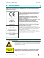
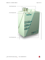
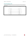
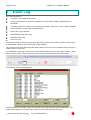
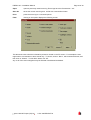
FIRElink-25 Air Sampling System
INSTALLATION MANUAL
Page 2 of 40
FIRElink-25 – Installation Manual
This manual details the installation of:
FIRElink-25 Air Sampling System
If you have any queries regarding these products or their functionality please contact:
Hochiki Europe (UK) Limited
Grosvenor Road
Gillingham Business Park
Gillingham
Kent ME8 0SA
Tel: +44 (0) 1634 260133
Fax: +44 (0) 1634 260132
Web: http://www.hochikieurope.com
Email: [email protected]
2010 Hochiki Europe (UK) Ltd. All rights reserved. No part of this document may be reproduced,
stored in a retrieval system, or transmitted, in any form or by any means, without the prior permission in
writing of Hochiki Europe (UK) Ltd.
Hochiki Europe (UK) Limited reserves the right to alter the specifications of its products from time to time
without notice. Although every effort has been made to ensure the accuracy of the information contained
in this document it is not warranted or represented by Hochiki Europe (UK) Limited to be a complete and
up-to-date description.
Document Details:
Title:
Issue
Issue Date
Part No.
FIRElink-25 Air Sampling System - Installation Manual
4.0
October 2010
9-5-0-344
2010 Hochiki Europe (UK) Ltd
9-5-0-344/ISS4/OCT10
FIRElink-25 – Installation Manual
Page 3 of 40
Table of Contents
1
Introduction.................................................................................................................................... 5
1.1
Indicators ............................................................................................................................... 6
1.2
Inside the Detector ................................................................................................................. 7
1.3
Detector Terminal Block Connections ..................................................................................... 8
2 Programming the Detector ............................................................................................................ 9
2.1
Time and Date tab.................................................................................................................. 9
2.2
Alarm Levels and Delays Tab ............................................................................................... 10
2.2.1
Alarm Levels - (Level subgroup) ....................................................................................... 10
2.2.2
Alarm Delays - (Delay subgroup)...................................................................................... 10
2.2.3
ClassiFire® Override........................................................................................................ 10
2.2.4
Alarm Factor .................................................................................................................... 10
2.2.5
LDD Enable ..................................................................................................................... 11
2.2.6
FastLearn Enable............................................................................................................. 11
2.2.7
Auto FastLearn Enable..................................................................................................... 11
2.2.8
ClassiFire 3D ................................................................................................................... 11
2.2.9
Demo Mode ..................................................................................................................... 11
2.3
Day/Night Switching Tab ...................................................................................................... 12
2.3.1
Day Start / Night Start –.................................................................................................... 12
2.3.2
Disable Day / Night Switching........................................................................................... 12
2.4
Alarm Actions Tab ................................................................................................................ 12
2.4.1
Remote Functions (Remote Input subgroup) .................................................................... 12
2.4.2
Programmed Isolate......................................................................................................... 12
2.4.3
Latching Alarms ............................................................................................................... 12
2.4.4
Latching Faults................................................................................................................. 12
2.4.5
Cascading Alarms ............................................................................................................ 12
2.5
Device Information Tab ........................................................................................................ 13
2.5.1
Device Type..................................................................................................................... 13
2.5.2
Firmware Version ............................................................................................................. 13
2.5.3
Run-time Hours................................................................................................................ 13
2.5.4
Watchdog Count .............................................................................................................. 13
2.5.5
Device Text...................................................................................................................... 13
2.6
Referencing Tab................................................................................................................... 13
2.6.1
Reference Detector .......................................................................................................... 13
2.6.2
Reference Enable ............................................................................................................ 13
2.6.3
Reference Level ............................................................................................................... 13
2.6.4
Reference Back-off .......................................................................................................... 13
2.7
Flow Monitoring Tab............................................................................................................. 14
2.7.1
Flow Rate......................................................................................................................... 14
2.7.2
Flow High Limit ................................................................................................................ 14
2.7.3
Flow Low Limit ................................................................................................................. 14
2.7.4
Flow Fault Delay .............................................................................................................. 14
2.8
Miscellaneous Tab ............................................................................................................... 14
2.8.1
Access Code.................................................................................................................... 14
2.8.2
Chart Recording Rate....................................................................................................... 15
2.8.3
Separator Condition ......................................................................................................... 15
2.8.4
Separator Change Date.................................................................................................... 15
2.8.5
Factory Default................................................................................................................. 16
2.9
Other Remote Software Features ......................................................................................... 16
2.9.1
Reset ............................................................................................................................... 16
2.9.2
Histogram Screen ............................................................................................................ 16
2.10
Chart Recording ................................................................................................................... 18
2.11
Load / Save Function Settings .............................................................................................. 18
3 Design Limitations ....................................................................................................................... 20
3.1
System Design ..................................................................................................................... 21
3.2
EN54-20 and UL238 Compliance ......................................................................................... 22
4 Installation.................................................................................................................................... 24
4.1
Docking Station .................................................................................................................... 24
2010 Hochiki Europe (UK) Ltd
9-5-0-344/ISS4/OCT10
Page 4 of 40
FIRElink-25 – Installation Manual
4.1.1
Mechanical Installation......................................................................................................25
4.1.2
Electrical Installation .........................................................................................................25
4.1.3
Power Supply Connections ...............................................................................................25
4.1.4
Signal Connections ...........................................................................................................25
4.2
Final installation ....................................................................................................................26
5 Interfacing .....................................................................................................................................28
5.1
Setting the Detector Address.................................................................................................28
5.2
Connecting a FIRElink-25 to a SenseNET/RS485 Detector Network......................................29
5.3
Connecting a FIRElink-25 to an addressable Fire Panel ........................................................29
5.4
Connecting to a PC ...............................................................................................................31
6 Event Log ......................................................................................................................................32
7 Commissioning.............................................................................................................................34
7.1
Commissioning Checklist ......................................................................................................34
8 Maintenance..................................................................................................................................35
8.1
Diagnostics ...........................................................................................................................35
9 Troubleshooting ...........................................................................................................................37
9.1
Nuisance Alarms Occur Too Often ........................................................................................37
9.2
Elevated Smoke Levels Do Not Generate Alarms..................................................................37
9.3
Low Mean Output..................................................................................................................37
9.4
Detector Sensitivity Varies Over Time ...................................................................................37
9.5
Flow Fault Errors...................................................................................................................37
9.5.1
"Low Flow" Error Messages. .............................................................................................38
9.5.2
"High Flow" Error Messages..............................................................................................38
10
Do's and Don'ts .........................................................................................................................39
11
FIRElink-25 Specification..........................................................................................................40
2010 Hochiki Europe (UK) Ltd
9-5-0-344/ISS4/OCT10
FIRElink-25 – Installation Manual
1
Page 5 of 40
Introduction
FIRElink-25 is a highly sophisticated ‘next generation‘ of High Sensitivity Aspirating Smoke Detection
product that has been designed to ensure that installation and commissioning is as simple as possible,
while optimising performance.
FIRElink-25 incorporates a patented ‘artificial intelligence‘ known
as ClassiFire ®, which allows the detector to configure itself to
optimum sensitivity, alarm thresholds and minimum nuisance
alarms for any environment.
0832
Hochiki Europe (UK) Limited
Grosvenor Road
Gillingham Business Park
Gillingham
Kent ME8 0SA, UK
ClassiFire intelligence also monitors the detector chamber and
dust separator for contamination, continually adjusting the
appropriate operating parameters to counteract the negative
effects of such contamination.
The FIRElink range of detectors is unique in being able to provide
a consistent level of protection in a very wide range of
environments by continuously making minor adjustments to
sensitivity.
09
0832-CPD-1194
The FIRElink range of detectors has proven its worth many times
by detecting ‘difficult-to-detect‘ slow growth electrical overload
incipient fires in ‘difficult‘ environments.
EN54-20: 2006
This handbook gives information likely to be needed for most
installations, but for more detailed information on subjects such as
Fresh Air Referencing, please refer to the complete Technical
Manual or System Design Guide.
Aspirating smoke detectors
for fire detection and fire alarm
systems for buildings
CLASS A, B and C
This equipment is Class 111 as defined in EN60950 (i.e., this
equipment is designed to operate from Safety Extra Low Voltages
and does not generate any hazardous voltages).
Technical data: see INF48027 held
by the manufacturer
NOTE: If this equipment is part of a fire detection system, it should be supplied from an approved power
supply conforming to EN54-4.
This symbol appears on the main board of the unit and indicates that the board
contains static sensitive components. Suitable anti-static precautions must be
taken when handling the board.
LASER CLASS 1
PRODUCT
This label is located on the laser chamber and signifies that the unit is a Class 1
Laser product as specified in IEC 60825-1. The unit incorporates a Class 3B
embedded laser which must not be removed from the detector as retinal
damage may result if the laser beam enters the eye.
2010 Hochiki Europe (UK) Ltd
9-5-0-344/ISS4/OCT10
Page 6 of 40
FIRElink-25 – Installation Manual
This symbol appears on the main board of the unit and indicates that the board
contains static sensitive components. Suitable anti-static precautions must be
taken when handling the board.
Hochiki Europe (UK) Limited has taken every care to ensure that FIRElink-25 is as simple to install as
possible but in case of difficulty, please contact our Product Support Department to ensure trouble free
installation and operation.
Hochiki Europe (UK) Limited takes no responsibility for damage or injury occasioned as a result of failing
to install or operate the equipment in accordance with these instructions.
1.1 Indicators
Fire indicator illuminates when
the alarm level has been
reached and the appropriate
time delays have expired.
Fault. Illuminates when the unit
has a fault and a fault signal is
being sent to the fire alarm
panel.
OK. Illuminates to show normal
operation when there are no
faults. The OK lamp will flash
during the 15 minute
Fastlearn™ period when the
detector is first learning about
its environment.
2010 Hochiki Europe (UK) Ltd
9-5-0-344/ISS4/OCT10
FIRElink-25 – Installation Manual
Page 7 of 40
1.2 Inside the Detector
Removable terminal
blocks (see section 1.3)
Filter (see section 8)
Addressable
programmable interface
card (FIRElink-APIC)
port (see section 5.3)
Detector address DIP
switch (see section 5.1)
RS232 serial port (see
section 5.4)
2010 Hochiki Europe (UK) Ltd
9-5-0-344/ISS4/OCT10
Page 8 of 40
FIRElink-25 – Installation Manual
1.3 Detector Terminal Block Connections
Normally
closed FAULT
relay contacts
Normally open
FIRE relay
contacts
2010 Hochiki Europe (UK) Ltd
FIRElink-APIC
addressable bus
connections for use in
conjunction with
interface card (see
sections 4.1.4 and 5.3)
9-5-0-344/ISS4/OCT10
RS485 / SenseNET
connections (see
sections 4.1.4and 5.2)
Power supply
connections (see
section 4.1.3)
FIRElink-25 – Installation Manual
2
Page 9 of 40
Programming the Detector
The FIRElink-25 may be programmed from a PC when connected to the detector via a standard 9-pin
serial lead connected to the serial port of the computer and the 9 way socket at the base of the detector
(see section 7.4, ‘Connecting to a PC’). In order to do this, it is necessary to install the remote control
software onto the computer. A copy of the remote control software is contained on a CD-ROM supplied
with each detector. Install the software in accordance with the on-screen instructions. To open the
software, select Start > Programs > Hochiki > Remote 3.0
The programmable functions are all accessed though the Options > Detector settings submenu or by
clicking on the detector button on remote software toolbar as indicated below:
The following screen is displayed:
This window contains all the programmable functions for the FIRElink-25. To amend one of the
programmable functions, go to the relevant tab, make the change and then click OK. This will save the
change to the detector’s internal firmware.
A list and explanation of the various functions is given below, with the functions grouped by the tab under
which they appear.
2.1 Time and Date tab
It is important that the time and date be set up correctly on the controller’s internal calendar/clock
because it uses this information to store events in the event log. See section 8, “Event log” for more
details. Unless specially ordered, units are supplied with the correct setting for UK time. This is backed
up with a rechargeable battery. Later adjustments to the clock setting should not exceed ± 70 minutes
unless a FastLearn is initiated.
2010 Hochiki Europe (UK) Ltd
9-5-0-344/ISS4/OCT10
Page 10 of 40
FIRElink-25 – Installation Manual
2.2 Alarm Levels and Delays Tab
2.2.1
Alarm Levels - (Level subgroup)
The value set in the Fire, Pre-Alarm and Aux functions in the Level subgroup is the relatively scaled
bargraph level at which the appropriate alarm is initiated on the detector. The Fire 2 level assigns an
absolutely scaled alarm level in % obs/m.
The Aux level is set by factory default at level 10 which means that this alarm will occur after the Fire
alarm. The default level settings for Pre-Alarm and Fire 1 are 6 and 8 respectively. The default setting for
Fire 2 is 20% obs/m.
2.2.2
Alarm Delays - (Delay subgroup)
The alarm delay is the number of seconds that an alarm level has to be continuously sensed before the
alarm is initiated. Each alarm level has a programmable delay of between 0 and 90 seconds. The default
delay for each alarm level is 5 seconds.
2.2.3
ClassiFire® Override
This function has no current use on the FIRElink-25 but is reserved for future expansion purposes.
2.2.4
Alarm Factor
The detector sensitivity is set with this entry, which will also affect the probability of nuisance alarms. 0 =
high sensitivity, higher probability, 8 = low sensitivity, lower probability. The default alarm factor is 4.
Note: The highest sensitivity setting is suitable for clean, environmentally controlled environments, e.g.
semiconductor manufacturing clean rooms where airborne pollutants are kept to an absolute
minimum and the least contamination is cause for alarm.
Use of this setting in a busy machine shop would lead to relatively frequent nuisance alarms due
to the normal variation of atmospheric contamination and a lower sensitivity setting is
recommended. It is therefore important that the alarm factor chosen is suitable for the area to be
protected. When the appropriate alarm factor for the protected area has been set, nuisance
alarms will be reduced to an absolute minimum.
The following table gives suggested settings of ClassiFire alarm setting for different locations:
Alarm
Factor
0
Sensitivity
Extremely High
Probability of
Nuisance Alarm
Suggested Protected Area
Once per year
Semiconductor manufacturing clean room
1
Once per 5 years
Computer room
2
Once per 10 years
Non-smoking office
3
Once per 50 years
Clean factory
4
Medium
Once per 1000 years
Warehouse
5
Medium
Once per 5000 years
Warehouse with diesel trucks operating
6
Medium
Once per 10000 years
Warehouse with diesel trucks operating
7
Low
Once per 20000 years
Warehouse with diesel trucks operating
8
Low
Once per 100000 years
Warehouse with diesel trucks operating
2010 Hochiki Europe (UK) Ltd
9-5-0-344/ISS4/OCT10
FIRElink-25 – Installation Manual
2.2.5
Page 11 of 40
LDD Enable
When this function is ticked, Laser Dust Discrimination (LDD™) increases the response time of the
detector slightly, whilst greatly reducing the likelihood of nuisance alarms due to dust ingress. LDD may
be disabled in very clean rooms for a slightly faster response to smoke by setting this function to unticking
the box. This function is enabled by default.
NOTE: Disabling LDD is not recommended for areas other than manufacturing clean rooms, due to the
increased probability of nuisance alarms in most other operating environments.
2.2.6
FastLearn Enable
If the detector is in FastLearn mode, unticking this box will stop the FastLearn process. Using the function
in this way is neither recommended nor supported by Hochiki Europe (UK) Limited.
Ticking the box will start a FastLearn at any time. The green “OK” LED on the front of the detector will
flash for the fifteen minutes that it takes for the FastLearn process, and will then change to constant
illumination to indicate that the FastLearn is complete.
Note: It will take a further 24 hours after the FastLearn for full sensitivity to be reached, unless
Demonstration Mode has been initiated (See section 3.10, “Demo mode”). It is essential for proper
functioning that the detector not be left in Demonstration mode, and that it be allowed to complete
the 24-hour learning period. To cancel demo mode, tick this box or power down and restart the
detector to initiate FastLearn mode.
2.2.7
Auto FastLearn Enable
When enabled, this function ensures that if the detector is powered off for any reason (e.g. for
maintenance or to be moved to a new area), a FastLearn is commenced automatically on power-up.
There may be occasions when it is desirable to power down the detector for short periods of time, and it
is highly likely that ambient contaminant levels will be the same on power-up. Under these circumstances
it may not be desirable that the detector should to go through the whole learning process again. To this
end, this function can be unticked before power-down, whereupon it will return to the original settings on
power-up. This function is enabled by default.
2.2.8
ClassiFire 3D
If this function is ticked, then the detector will ignore any pre-set time delays in the event of an
unacceptably rapid increase in smoke density, thereby minimising response time to 'rapid growth' fires.
This function would normally only be used where there were long time delays programmed on the alarm
levels. This function is disabled by default.
2.2.9
Demo Mode
Demonstration mode is an operating mode whereby the normal 24-hour learning period is bypassed, so
that the detector can reach high sensitivity after only the 15 minute FastLearn period. This can be used so
that initial smoke testing and other commissioning can be carried out.
However, it must be understood that, since the alarm levels will be based solely upon the
sparse data gathered during the FastLearn period, there is a risk of nuisance alarms due
to normal variations in ambient smoke levels. For this reason, the detector should not be
left in Demo mode for normal use when connected to a fire panel.
2010 Hochiki Europe (UK) Ltd
9-5-0-344/ISS4/OCT10
Page 12 of 40
FIRElink-25 – Installation Manual
2.3 Day/Night Switching Tab
2.3.1
Day Start / Night Start –
These values are the times to the nearest hour at which the day/night switching is desired to take place
on the detector. Entries are made in 24-hour format, e.g. 19 for 7pm. Day and night switching is intended
so that the detector may automatically select a different sensitivity when the protected area is unoccupied
and fewer contaminants are being produced. ClassiFire automatically detects the change in smoke level
after the protected area is left, and if the time at which this happens is within + 70 minutes of the
programmed switchover time it selects the night-time histogram. This means that changes in time setting,
for example changing to summer time, may be ignored as the detector will take this into account. The
default times for day and night start are 08:00 and 19:00 respectively.
NOTE: That if the environment actually becomes more contaminated during the night period for any
reason then ClassiFire will adapt to that too, reducing the night-time sensitivity.
2.3.2
Disable Day / Night Switching
If day/night switching is not desirable, the Disable day/night switching box may be ticked to leave the
detector permanently in day mode.
2.4 Alarm Actions Tab
2.4.1
Remote Functions (Remote Input subgroup)
These functions have no current use on the FIRElink-25 but are reserved for future expansion purposes.
2.4.2
Programmed Isolate
When this function is ticked the controller will not generate alarms and will not indicate a fault condition on
any fire panel which is connected, e.g. for use during detector maintenance. The “Fault” light will be
illuminated on the detector front panel. The isolated condition will be disabled automatically after 7 days if
not manually disabled. This function is disabled by default.
2.4.3
Latching Alarms
When this function box is ticked it requires a reset from the controlling computer to clear an alarm
condition. If unticked, the alarm signal is extinguished as soon as the alarm condition ends. This is the
factory default setting.
2.4.4
Latching Faults
When this function box is ticked it requires a reset from the controlling computer to clear a fault condition.
If unticked, the fault signal is extinguished as soon as the fault condition ends. This is the factory default
setting.
2.4.5
Cascading Alarms
Ticking this function box means that only when the detector’s controller has gone into Pre-Alarm does the
controller start counting down the main Fire delay i.e. the time delays on Pre-Alarm and Fire 1 are
cumulative. The Aux alarm is not included in the cumulative delay since it may be set to a higher level
than either the Pre-Alarm or Fire 1 levels. This function is enabled by default.
2010 Hochiki Europe (UK) Ltd
9-5-0-344/ISS4/OCT10
FIRElink-25 – Installation Manual
Page 13 of 40
2.5 Device Information Tab
2.5.1
Device Type
This function is for display purposes only. It shows any special designation for the unit, which will normally
be FIRElink-25.
2.5.2
Firmware Version
This function is for display purposes only. It shows the version number of the fitted firmware chip.
2.5.3
Run-time Hours
This function is for display purposes only. It shows the cumulative total number of hours that the device
has run (this is not the time that has elapsed since last power-up, but the sum total of run time since the
detector memory was last reset).
2.5.4
Watchdog Count
The watchdog is a circuit built into the controller that restarts the controller in the event of a failure to
function properly. This could be as a result of electrical spikes. This count shows the number of
interruptions found. The details of each problem can be found in the event log. See section 6, “Event
Log” for further details.
2.5.5
Device Text
This function has no current use on the FIRElink-25 but is reserved for future expansion purposes.
2.6 Referencing Tab
2.6.1
Reference Detector
A FIRElink detector may use another detector as a fresh air reference. This function is the address of the
detector which will be used as the reference. To set a detector as a reference detector, enter its address
as set by its internal DIP switch into this function. This function is disabled by default.
2.6.2
Reference Enable
Ticking this box enables the reference for the detector, if one has previously been allocated in Reference
detector (see section 2.6.1). This function is disabled by default.
2.6.3
Reference Level
The value set with this function is the percentage reference signal subtracted from the detector’s signal, if
a reference device has been allocated. The default value is 0.
2.6.4
Reference Back-off
This value is the delay time between a build up of pollution being seen by the reference (if used) and the
pollution being seen by the detector. The default value is 15.
2010 Hochiki Europe (UK) Ltd
9-5-0-344/ISS4/OCT10
Page 14 of 40
FIRElink-25 – Installation Manual
2.7 Flow Monitoring Tab
2.7.1
Flow Rate
This function is for display purposes only, and shows a value corresponding to the current airflow through
the detector.
2.7.2
Flow High Limit
This value is the level above which airflow needs to increase to trigger a fault indication (which may
indicate a loose or damaged inlet pipe). Flow low limit and Flow high limit parameters are automatically
set up on initial power-up.
2.7.3
Flow Low Limit
This value is the level below which airflow needs to be reduced to trigger a fault reading (which may
indicate a blocked pipe). Flow low limit and Flow high limit parameters are automatically set up on initial
power-up
2.7.4
Flow Fault Delay
This feature requires the Remote Control Software version 3.2 or later, available from the Hochiki Europe
Technical Support Department ([email protected]).
The default flow fault thresholds on the FIRElink-25 are set to meet the stringent airflow monitoring
requirements of EN54-20, with a default flow fault delay of 30 seconds. This may lead to unwanted flow
faults being generated when local conditions cause short-term variations in airflow. To help alleviate such
issues, the flow fault delay is programmable from 30 to 240 seconds. The flow level needs to be above
the high flow threshold or below the low flow threshold throughout the delay period for a fault to be
generated.
NOTE: When setting the value of this function, it is important to take into account that the control unit (for
example, fire panel) may not react immediately to a trouble signal being generated by the
detector, and this will add to the total fault response time of the system.
The function value must be chosen so that the total time between the detector entering a fault condition
and a fault signal being generated by the panel meets the requirements of local or national fire
regulations. The maximum allowable response time for EN54-20 compliance is 300 seconds, and that for
NFPA 72 compliance is 200 seconds.
As an example: in the latter case, if the flow fault delay were set to 180 seconds (within the limit), but the
fire panel did not generate a fault indication for another 25 seconds, the total response time of 205
seconds means the system would not comply with the regulations.
If documented figures are unavailable for the fire panel reaction time, compliance with reaction time
regulations may only be verified by post-installation testing.
2.8 Miscellaneous Tab
2.8.1
Access Code
This is the access code required to amend programmable parameters. The default code is 0102. Once
the appropriate code is entered it may be changed here to any four digit number to limit unauthorised
access.
2010 Hochiki Europe (UK) Ltd
9-5-0-344/ISS4/OCT10
FIRElink-25 – Installation Manual
2.8.2
Page 15 of 40
Chart Recording Rate
This function controls how frequently the detector and alarm level or flow rates are stored in the FIRElink25’s internal chart recorder log. (See section 2.10, ‘Chart Recording’).
Setting
Type
Storage Interval
Time per Division on Chart Log
0
Detector Output
1 second
10 seconds
1
Detector Output
5 seconds
50 seconds
2
Detector Output
12 seconds
2 minutes
3
Detector Output
30 seconds
5 minutes
4
Detector Output
1 minute
10 minutes
5
Detector Output
2 minutes
20 minutes
6
Detector Output
5 minutes
50 minutes
7
Detector Output
10 minutes
100 minutes
8
Detector Output
20 minutes
200 minutes
9
Detector Output
50 minutes
500 minutes
10
Flow Recording
1 second
10 seconds
11
Flow Recording
5 seconds
50 seconds
12
Flow Recording
12 seconds
2 minutes
13
Flow Recording
30 seconds
5 minutes
14
Flow Recording
1 minute
10 minutes
15
Flow Recording
2 minutes
20 minutes
16
Flow Recording
5 minutes
50 minutes
17
Flow Recording
10 minutes
100 minutes
18
Flow Recording
20 minutes
200 minutes
19
Flow Recording
50 minutes
500 minutes
In the above table the shaded cells indicate flow rate recording whilst the white cells indicate detector and
alarm level recording.
At the slowest recording rate, one month of data can be recorded. The factory default setting is 8.
2.8.3
Separator Condition
The value given at this function is the efficiency rating of the dust separator element in the detector as a
percentage of the efficiency of a clean separator. A new element will give a reading of 99 in this function.
When the efficiency has decreased to 80%, the Fault indicator LED will illuminate and the event log will
show “Separator renew”.
NOTE: Fitting a new element will reset this figure to 99
2.8.4
Separator Change Date
This function defaults to “--“, which means that a separator fault will only appear when the efficiency
decreases to 80% (see 2.8.3, “Separator Condition”). However, a date may be entered into this function
2010 Hochiki Europe (UK) Ltd
9-5-0-344/ISS4/OCT10
Page 16 of 40
FIRElink-25 – Installation Manual
to allow for a scheduled maintenance period. The detector will then generate a separator fault at the
planned time regardless of the condition of the separator, although degradation of the separator to below
80% efficiency before this date will override this. See section 8, “Maintenance” for further details.
2.8.5
Factory Default
Enabling this function will reset each programmable function to the default value indicated in the text,
where a default setting is specified. It will also put the detector into FastLearn mode, regardless of
whether or not Auto Fastlearn is enabled (see section 2.2.7). This ensures that the flow setups and alarm
thresholds are optimised to the detector’s working environment after resetting. It should be noted that
where a ClassiFire alarm factor other than the default is required for the protected area, this will need to
be re-entered. Section 2.2.4 gives details of the ClassiFire alarm factors.
2.9 Other Remote Software Features
2.9.1
Reset
If latching alarms (see section 2.4.3) or latching faults (see section 2.4.4) are enabled, the relevant alarm
or fault warnings will remain on the detector front panel LEDs and controlling unit until a reset is
performed. If using SenseNET software, individual detectors can be reset (refer to the SenseNET User
Guide for details). In the remote software, a global reset is available which resets all detectors on the
SenseNET loop, or a single stand-alone detector.
To perform a reset, either select the menu options Options > Global Reset or click the button on the
toolbar as indicated below:
2.9.2
Histogram Screen
The histogram screen shows various aspects of the detector function. To enter the histogram screen,
either select the menu options View > Histogram Viewer, or click the button on the toolbar as indicated
below:
The following screen is displayed:
2010 Hochiki Europe (UK) Ltd
9-5-0-344/ISS4/OCT10
FIRElink-25 – Installation Manual
Page 17 of 40
Smoke Density histogram
Alarm flags
There are two types of smoke density histogram; one shown in blue (the “fast” histogram) which updates
every 15 minutes, feeding information to the long-term “slow” histograms (which appear in yellow). These
set the detector sensitivity based on the ambient smoke conditions and it takes 24 hours for the two slow
histograms (the “day” and the “night” histograms) to complete their learning phase (see section 2.2.6).
Detector sensitivity is based on the fast histogram during FastLearn and is thereafter based on the
currently active slow histogram. However, although the positions of the alarm flags are based on the slow
histogram, sudden changes in smoke density are picked up by the fast histogram so that early warning is
given.
Sensitivity: The current absolute sensitivity of the detector in percentage obscuration per metre (%
obs/m)
Mean: The current mean value of smoke density, taken from the currently “active” histogram and given
as a percentage of full scale deflection.
Variance: The “spread” of data in the currently “active” histogram and given as a percentage of full scale
deflection.
FastLearn: If the detector is currently in FastLearn mode, this will show the number of minutes
remaining in the FastLearn period. When this period has elapsed it will read “OFF”.
Alarm factor: This is the ClassiFire alarm factor (see section 3.5, “Alarm factor”)
Day/night: This indicates the currently active slow histogram
Alarm levels: These figures give the position of the various alarm flags in terms of a percentage of full
scale deflection.
Detector output: This shows the real-time variation in background smoke levels in terms of a
percentage of full scale deflection.
2010 Hochiki Europe (UK) Ltd
9-5-0-344/ISS4/OCT10
Page 18 of 40
FIRElink-25 – Installation Manual
2.10 Chart Recording
The chart recording function shows how smoke density in the protected area has varied over time. The
chart may be downloaded to disk or printed out from a connected printer.
To access the chart log, select the menu options View > Chart Recording or click the button on the
toolbar as indicated below:
The following screen is displayed:
The red trace is the current alarm level and the black trace is the detector output. By moving the cursor
along the chart, the “Chart information” window (shown at the bottom left) updates to show the date and
time, detector level and alarm level of the relevant period. The File menu option in the chart recording
window allows the chart recording to be saved to disk or printed to a connected printer, and allows a
previously saved chart recording to be loaded. Chart recording files have the extension “.rcw”.
2.11 Load / Save Function Settings
Where a custom set of programmable function settings is commonly used, these may conveniently be
saved to or loaded from disk. To open a detector function settings (.dfs) file, select the menu options File
> Open or click on the button on the toolbar as indicated below:
A file browser window will be displayed, click on the “List files of type” drop-down box and select “Detector
settings (*.dfs)” as indicated below:
2010 Hochiki Europe (UK) Ltd
9-5-0-344/ISS4/OCT10
FIRElink-25 – Installation Manual
Page 19 of 40
A list will appear of all detector settings files stored on the current drive. As a special case, if desiring to
recall the factory default settings, there is a file named ‘default.dfs’ in the ‘remote2k’ directory. Loading
this file will reset the detector to the factory default.
2010 Hochiki Europe (UK) Ltd
9-5-0-344/ISS4/OCT10
Page 20 of 40
3
FIRElink-25 – Installation Manual
Design Limitations
FIRElink-25 is intended to provide LOCALISED incipient fire detection only. This
means that it is suitable for the substantial range of applications typified by; small
non-compartmentalised rooms, warehouse racking, or pieces of electronic or
electromechanical equipment where it is desirable to achieve individual incipient fire
reporting. In compartmentalised rooms, each compartment would normally use
individual FIRElink-25 detectors.
This product employs a very low-power aspirator and the aspirating capability of the FIRElink-25 detector
is limited accordingly. FIRElink-25 is NOT intended to protect large areas, or to sample from areas where
there may be any difference in airflow rates or pressure differentials. Application of FIRElink-25 in these
circumstances is not recommended. If detection in environments conforming to these descriptions is
required, alternative versions of FIRElink products should be used.
Maximum recommended sampling pipe length is 50 metres in STILL AIR. In areas or applications where
the external airflow rate is greater than 1 metre per second, the maximum sampling pipe length is
reduced to 25 metres.
Although by no means essential, it must be recommended that if in doubt, PipeCAD® be used to ensure
that transit times, balance of suction and individual sampling point sensitivity are within desired limits.
Sampling pipes must have capped ends. The end cap should be drilled with a hole normally between 4
or 5mm diameter and free from burrs. Sampling holes should normally be 3-4mm diameter or as
calculated by PipeCAD, and free from burrs. Each pipe run should not have more than 10 holes
(including the end cap hole). Pipe transit time from the furthest sampling hole from the detector must not
exceed 120 seconds and an approved type of pipe must be used for installations conforming to LPCB
requirements. It is strongly recommended that the smoke transit time from the furthest sampling hole be
checked during commissioning tests. Capillary Remote Sampling Points may be used in place of
sampling holes.
FIRElink-25 is supplied with a ‘Piped Exhaust’ type Docking Station (see illustration A). This is primarily
intended to allow the FIRElink-25 detector to sample from areas which may be at different air pressure to
the detector location. Typical uses are for air-duct sampling and allowing the installation of the detector in
under-floor or ceiling voids or when sampling from pieces of computer related equipment.
A
Above Ceiling
Sampling with
exposed detector.
2010 Hochiki Europe (UK) Ltd
9-5-0-344/ISS4/OCT10
FIRElink-25 – Installation Manual
Page 21 of 40
B
Above Ceiling
Sampling with
detector
mounted in
ceiling void.
3.1 System Design
Simple designs with short sampling pipes produce the best results. Complex sampling pipe runs should
be avoided with the FIRElink-25 detector. The use of ‘T’ branch-pipes is not recommended. To assist in
design and to verify system performance, it is advisable to use the FIRElink PipeCAD® sampling pipe
modelling software.
Always locate the sampling points in positions to which smoke may reasonably be expected to travel. Do
not expect ceiling mounted sampling points to operate satisfactorily if air flow from air-conditioning
systems keeps the cool smoke from an incipient fire reaching from reaching ceiling level. In this instance
it is usually better to locate the sampling pipe directly in the airflow (for example across the return air
register of an air conditioning unit).
There is no substitute for carrying out smoke tests prior to installation of pipe work to indicate suitable
sampling point location.
No more than ONE Air Handling Unit may be protected with one FIRElink-25 detector. In this application,
ensure that the sampling pipe is raised clear of high velocity air in the immediate vicinity of the air intake
grille on stand-off posts as shown below:
2010 Hochiki Europe (UK) Ltd
9-5-0-344/ISS4/OCT10
Page 22 of 40
FIRElink-25 – Installation Manual
3.2 EN54-20 Compliance
The installation must be designed using PipeCAD software, which is provided free on the CD shipped
with each detector. After designing the installation including pipes, endcaps and sampling holes, enter
the detector type in the “Type” drop-down list in “Options” “Calculation options”.
Select “Options” “Calculate” or click on the calculator icon. The software will prompt you to choose from
“Use set hole sizes” “Best flow balance” and “Max. permissible transit time”. Select the appropriate option
and click “OK”. The results for each pipe (“View” “Results”) show calculations for each sampling hole on
the pipe with the nearest to the detector at the top of the screen, and the endcap hole at the bottom.
“Transit time” shows the smoke transit time to the detector from each sampling hole. For EN54-20, this
must be below 120 seconds from every hole. The column headed “Hole sensitivity % obs/m” shows the
predicted sensitivity for each hole. For the installation to comply with EN54-20, each sampling hole must
be no less sensitive than 0.31% obs/m.*
The calculation can be further refined by leaving a working detector in the protected area for at least
24hrs at the intended alarm factor for the installation (this could be done before or after installation). The
detector sensitivity can be read from the “Sensitivity” figure on the histogram screen of the Remote
software supplied with each detector. Enter this figure into the PipeCAD calculation under “Options”
“Calculation options”, “Detector sensitivity”. Clicking on “OK” will update the hole sensitivities to the figure
expected for the actual layout.
Commissioning and periodic system tests must involve smoke tests to verify that the system performs as
expected and enters Fire 1 alarm within 120 seconds from the farthest hole. The detector sensitivity must
also be inspected to ensure it has not radically fallen from the installed figure. If it has changed for any
reason. the new figure must be re-entered into PipeCAD and the recalculated hole sensitivities must be
confirmed to be within the class limits shown above. The settings of a compliant system should be
recorded, as it is possible by changing certain programmable functions to make the system non2010 Hochiki Europe (UK) Ltd
9-5-0-344/ISS4/OCT10
FIRElink-25 – Installation Manual
Page 23 of 40
compliant. If functions are changed, it is recommended that the system is retested if continuing
compliance is in any doubt.
*The results should be verified at installation by entering the installed detector's Fire 1 sensitivity (as
indicated in the remote software histogram screen) into the PipeCAD “Options/Calculation
options/Detector sensitivity” field and recalculating the layout results.
2010 Hochiki Europe (UK) Ltd
9-5-0-344/ISS4/OCT10
Page 24 of 40
4
FIRElink-25 – Installation Manual
Installation
Before installing the detector the local standards for installation of aspirating detection systems must be
consulted as these standards differ throughout the world. Specific advice for one country may not be
applicable to another. The following is a brief set of guidelines on installing detectors:
The detector will normally be mounted at a level where there is easy access to the unit for
configuration and programming.
The exhaust air from the unit must not be impeded in any way. If the unit is mounted in a different
air pressure from where the air is being sampled (for example an air duct), then a pipe must be
taken from the exhaust port back to the same air pressure zone as the sampling holes.
Sampling holes should be free from burrs and swarf.
All signal cables must be screened and must be of a suitable type. The specific type of cable will
normally depend upon the local fire regulations.
The unit must not be placed in areas where either the temperature or humidity is outside the
specified operating range.
The unit should not be placed in close proximity to any equipment expected to generate high Radio
Frequency levels (such as radio alarms) or units generating high levels of electrical energy (such
as large electric motors or generators).
In order for the installation to conform to EN54-20, pipes must conform at least to EN61386-1 Class
1131
4.1 Docking Station
The basic principle behind installation of the FIRElink-25 is that all wiring and pipe-work is installed using
a docking station. This is a convenient feature which means that the detector can be dismounted or
replaced without disturbing any wiring or installed pipe-work.
2010 Hochiki Europe (UK) Ltd
9-5-0-344/ISS4/OCT10
FIRElink-25 – Installation Manual
Page 25 of 40
Piped Exhaust Docking Station
4.1.1
Mechanical Installation
The docking station is connected to the installed sampling pipe-work and fixed to the wall or mounting
surface using 3 off screws of a type appropriate to the mounting surface. Ensure that the sampling and/or
exhaust pipes are securely seated in the pipe ports before fixing. If using a piped exhaust docking station
be sure that the sampling and exhaust pipes are fitted into the relevant ports as shown in section 4.1.
4.1.2
Electrical Installation
The FIRElink-25 detector is supplied with removable terminal blocks (See illustrations in Section 0).
These are simply removed from their sockets by lifting them up at right angles to the circuit board. Take
note of the orientation of each terminal block and its function before removing it. It may also be beneficial
to mark the connection wires with suitable identification labels or coloured rings to aid in the connection
process.
NOTE: All connections should be made with the power turned off.
4.1.3
Power Supply Connections
The power supply cable should be of screened type and should be led through the metal cable gland
provided, leaving about 35mm of the cable extending from the bottom of the cable gland. Depending on
the type of cable used, it may be necessary to increase the diameter of the cable with sleeving or
insulating tape to ensure that the cable is firmly held when the cable gland is fully tightened.
Remove the detector cover by unfastening the four screws at the front of the unit and detach the power
supply terminal block. This is at the top left with the detector held with the serial port at the bottom of the
unit.
NOTE: Be aware of the orientation of the terminal block.
Connect 0V and +24VDC to the “0V” and “24V” screw terminals respectively. Connect the screen wire to
the earth stud on the docking station and connect a second wire from the “Earth” terminal to the docking
station earth stud. The picture in Section 4.1 shows the location of the earth stud. Fix the earth wires in
place with the nuts provided.
4.1.4
Signal Connections
To connect the signal wire, lead a suitable wire type (RS485
cable 9841, 120 ohm screened twisted pair or equivalent)
through the second cable gland and tighten it into position with
about 35mm of cable from the bottom of the cable gland.
Remove either the three-way terminal block next to the power
supply socket if connecting the detector to a SenseNET
system, or the four-way “Bus” terminal block if connecting the
detector to an alarm panel in conjunction with the FIRElinkAPIC addressable programmable interface card (see section
5.3).
FIRElink-APIC RS485/SenseNET
Terminals
Address
Terminals
2010 Hochiki Europe (UK) Ltd
For example, in a SenseNET system using screened cable
connect the screen wire(s) to the “SCN” terminal, Bus A wire(s)
to the “A” terminal and Bus B wire(s) to the “B” terminal. If the
detector is in the middle of a SenseNET chain, with input and
output connections, it may be more convenient to link the
common Bus A, Bus B and screen wires to single A, B and
screen wires for linking to the terminal block.
9-5-0-344/ISS4/OCT10
Page 26 of 40
FIRElink-25 – Installation Manual
The following illustration shows the power and signal connections to the docking station for connection to
a single SenseNET cable:
Power Supply Screen Wire to Earth Stud
SenseNET/RS485
Bus A Wire
SenseNET/RS485
Bus B Wire
SenseNET/RS485
Bus Screen Wire
Power Supply
0V Wire
Wire from "Earth" Terminal to Earth Stud
Power Supply +24V Wire
4.2 Final installation
Once the power and signal connections are made slide the detector body up into the docking station and
fasten it into position using the M4 pan head screws provided. Slot the power and signal terminal blocks
into the relevant sockets on the detector PCB (they will only click fully home in the correct orientation) and
replace the detector cover using the four M3 pan head screws provided.
NOTE: The detector is designed solely for operation with the front cover securely fitted using all four fixing
screws.
Removing the detector is simply the reverse of this process, leaving the pipe-work and wiring connections
installed in the docking station.
2010 Hochiki Europe (UK) Ltd
9-5-0-344/ISS4/OCT10
FIRElink-25 – Installation Manual
Page 27 of 40
Dock Fixing Screws
Cover Fixing Screws
Cover Fixing Screws
2010 Hochiki Europe (UK) Ltd
9-5-0-344/ISS4/OCT10
Page 28 of 40
5
FIRElink-25 – Installation Manual
Interfacing
Because of the flexible nature of the FIRElink-25 detector and the many possible configurations, there are
many options for interfacing the detectors to the Fire Panel. These include many third party interfaces
available from various manufacturers. Because of this, it is not possible to give a complete list of all
interfacing methods but the following pages will give details of the most common methods that are likely
to be used.
5.1 Setting the Detector Address
In order to identify itself to the PC Command Module or fire panel, each detector needs to have a unique
address ranging from 1 to 127. The detector address is simply set on the red DIP switch SW1 at the top
left of the opened detector on the main circuit board. The switch settings are on for 1 and off for 0, and
the detector address is set as a 7-bit binary code (switch 8 equates to a value of 128 and so is outside the
usable address range). An example is shown below.
The address equates to 01100011 in binary, or (1 x 1) + (1 x 2) + (0 x 4) + (0 x 8) + (0 x 16) + (1 x 32) +
(1 x 64) + (0 x 128) = 99.
The full range of available addresses and their relevant switch settings are shown below:
2010 Hochiki Europe (UK) Ltd
9-5-0-344/ISS4/OCT10
FIRElink-25 – Installation Manual
Page 29 of 40
5.2 Connecting a FIRElink-25 to a SenseNET/RS485 Detector
Network
Up to 127 detectors may be linked in a single SenseNET bus, supporting a total length of wire between
adjacent detectors of up to 1.2km.
In the above example, two FIRElink-25 detectors are linked into a 127-detector bus with a Command
Module and a number of other FIRElink detectors. It will be noted that whereas the FIRElink-400 units
have two input / output buses (1A / 1B and 2A / 2B), the FIRElink-25 has only a single such bus (A / B)
and therefore each bus terminal has an input and an output wire, compared with a single wire in each
terminal in the FIRElink-400.
For this reason, it may be easier to join the input and output wires for each bus and screen connections
together and to solder or crimp a single wire or connecting ferrule to each wire pair so that they are easier
to fit into the screw terminals. If this is done it is recommended that bare wire joints be insulated to
prevent possible shorting of the data bus, which will cause a drop-out of data on the SenseNET bus.
In the above example, there could be a total length of RS485 cable of up to 1.2km between the
Command Module and Detector 3, since these are all on a single bus. However, Detector 3 is a
FIRElink-400 which has a second communications bus (RS485 bus 2) and an RS485 repeater. This
allows a further total of 1.2km of cable until the next FIRElink-400 in the RS485 loop.
In the above example, if detectors 4-126 (not shown) were all of the FIRElink-25 type then the total length
of wiring between detectors 3 and 127 would be limited to 1.2km. However, each additional FIRElink-400
detector wired up using both RS485 buses would allow an additional 1.2km of cabling to be added to the
RS485 loop.
5.3 Connecting a FIRElink-25 to an addressable Fire Panel
An Addressable Programmable Interface Card (FIRElink-APIC) may be used to decode detector
information and to relay this to a Fire Panel.
The FIRElink-APIC is fitted to the four mounting studs on the FIRElink-25 PCB using the supplied screws
as shown below:
2010 Hochiki Europe (UK) Ltd
9-5-0-344/ISS4/OCT10
Page 30 of 40
FIRElink-25 – Installation Manual
FIRElink-APIC
Mounting Studs
FIRElink-APIC
Address Switches
(x 2)
FIRElink-APIC
Interface
Connection
The connections to the Fire Panel are made using the BUS L1 and H1 (bus 1 input and output) and the
BUS L2 and H2 (bus 1 input and output) terminal connectors shown in Section 4.1.4.
The only settings that need to be made are on the FIRElink-APIC address DIP switches. The start loop
address Is entered on SW1 and the end loop address on SW2. In the case of a single FIRElink-25 the
start and end addresses will be the same.
NOTE: The detector address on the SenseNET loop and the Fire Panel addressable protocol address are
the same, in other words, no address translation is performed. Some protocols may not support
all the available alarm levels and fault reporting is usually a general fault with no detailed fault
information. Please consult the specific FIRElink-APIC documentation for more information.
2010 Hochiki Europe (UK) Ltd
9-5-0-344/ISS4/OCT10
FIRElink-25 – Installation Manual
Page 31 of 40
5.4 Connecting to a PC
To connect a single stand-alone detector to a PC, connect the PC‘s serial port directly to the detector‘s 9way RS232 port, which is situated on the bottom surface of the detector case. Connections for this cable
are shown below:
2010 Hochiki Europe (UK) Ltd
9-5-0-344/ISS4/OCT10
Page 32 of 40
6
FIRElink-25 – Installation Manual
Event Log
An event is defined as
a change to any programmed function
a signal received from an external controller such as the remote software, FIRElink-APIC or
SenseNET
a detector output level meeting or exceeding the Pre-Alarm, Aux, Fire 1 or Fire 2 alarm thresholds
a fault condition such as a flow or separator fault
start of day / night operation
demonstration mode start / stop
FastLearn start / stop
Power on or off
The detector stores an internal log of the last 200 events, and this can either be viewed on a PC screen
or downloaded to disk by use of the remote control software.
When the event log is full (200 events are stored) and a new event occurs, the oldest event in the log is
deleted (First-In, First-Out).
To download the event log, connect a PC to the detector serial port and run the remote software. Either
select the menu options View > Event Log or click on the event log symbol as indicated below:
The following screen will be displayed:
This shows the time and date of each event stored in the log along with its general description. The
buttons at the bottom of the screen allow control over the input and output of the log.
2010 Hochiki Europe (UK) Ltd
9-5-0-344/ISS4/OCT10
FIRElink-25 – Installation Manual
Page 33 of 40
Open:
opens a previously saved event log. Event logs have the file extension “.evl”.
Save As:
saves the current event log as a .evl file with a user defined name.
Print:
prints the event log to a connected printer.
Filter:
clicking on this option displays the following screen:
This allows the user to limit the information printed or viewed on the PC screen. For example the user
might wish to concentrate on alarm events only. To do this, click on “None”, which unticks all boxes, and
then click on “Alarms”. To tick all the boxes, tick “All”.
Any or all of the event categories may be selected or deselected as desired.
2010 Hochiki Europe (UK) Ltd
9-5-0-344/ISS4/OCT10
Page 34 of 40
7
FIRElink-25 – Installation Manual
Commissioning
Before commissioning the detector the local standards of aspirating detection systems must be consulted.
These standards differ widely throughout the world and specific advice for the market in one country may
not be applicable to another.
Commissioning strategy will initially depend upon the environment in which the detector is installed. For
instance, the test for a computer room (which should be a relatively clean environment) would be very
different from, say, a flour mill, which would probably have a high level of airborne particulate content.
A widely accepted standard for computer rooms/EDP areas is British Standard BS6266, equipment
overheating at a stage well before combustion. To perform the test electrically overload a 1 metre length
of PVC insulated wire of 10/0.1mm gauge for one minute using an appropriate power supply. The
detector has two minutes from the end of the wire burn to give an alarm indication.
For areas with higher levels of background particulate matter testing methodology would be similar to that
of standard point detectors.
7.1 Commissioning Checklist
The following brief checklist allows quick setup of the detector. This procedure will be adequate for most
standard installations.
1. Before powering up the detector, visually check all cabling to ensure correct connection. If wire
identification is not immediately clear (for example, by use of different coloured wires or wire
identification sleeves) an electrical check should be made. Any damage caused by misconnection of
the detector is not covered by warranty.
2. Power up the unit and connect to a PC and set the address switches on the detector board (see
section 5.1) and FIRElink-APIC board if applicable (see section 5.3).
3. Verify that the time and date are correct (see section 2.1)
4. Set an appropriate alarm factor for the protected environment. The detector will perform a FastLearn
for the new alarm factor. (see section 2.2.6)
5. Whilst the detector is still in FastLearn mode set the detector into demonstration mode (see section
3.10).
NOTE: Aerosol-type synthetic smoke sources should not be used to test the response of the detector as
these may leave acidic residues which could cause damage to the unit.
6. Wait for the FastLearn to finish and the flashing OK LED indicator will finish and perform any
necessary smoke tests, ensuring that the detector reacts appropriately (within 120 seconds for LPCB
compliance), and let the smoke fully dissipate.
7. Perform another FastLearn, this time not putting the detector into demonstration mode. The detector
will generate no alarms during the 15 minute FastLearn period, and after this the detector will operate
at a reduced sensitivity for 24 hours whilst ClassiFire acclimatises to the protected environment and
sets up appropriate day and night sensitivity settings.
2010 Hochiki Europe (UK) Ltd
9-5-0-344/ISS4/OCT10
FIRElink-25 – Installation Manual
8
Page 35 of 40
Maintenance
FIRElink-25 is a very low maintenance detection system. If required, external cleaning of the unit should
be performed using a damp (not wet) cloth. Do not use solvents as these may mar the front panel label.
The only part that may require field replacement during servicing is the dust separator assembly. The
dust separator condition can be checked using the Dust Separator test in the Miscellaneous tab of the
remote software ‘Detector settings’ screen (see section 2.8.3) which gives a percentage reading of dust
separator efficiency. When this level drops to 80% the detector will signal a fault and the dust separator
will need replacing. To replace the filter, simply remove the front cover and pull the filter out from the
main unit. Slide the replacement filter in so that the ‘Direction of flow’ arrow printed on the carton
duplicates that on the ‘Direction of flow’ label beside the filter slot.
As dust contained in the dust separators may expose maintenance personnel to a ‘Nuisance Dust‘ hazard
as defined by the ‘Control of Substances Hazardous to Health‘ (COSHH), it is strongly recommended that
suitable masks and protective clothing be worn when changing filters. Used separators are not
intended for re-use and should be disposed of.
8.1 Diagnostics
The remote control software includes a diagnostic function which carries out a number of checks to verify
the correct functioning of the detector. A good time to run these tests is as a part of planned
maintenance. To call up diagnostic mode, select the menu options View > Diagnostics or click on the
symbol indicated below:
The following message will be displayed:
The software will then scan the loop for up to 127 detectors. For a single detector, wait until the first
detector has been identified and the window indicates that it is scanning for Detector 2, then press the
Cancel button.
The following window is displayed:
2010 Hochiki Europe (UK) Ltd
9-5-0-344/ISS4/OCT10
Page 36 of 40
FIRElink-25 – Installation Manual
Click on the list entry to highlight it and click on the Diagnostics button. The software will then
commence the system tests. During the “Aspirator and flow” test, the detector fan will suddenly slow
down, but this is a normal part of the test.
When the test has finished and no problems have been found, the following screen is displayed:
If any problems were found during the diagnostic tests, the nature of the fault will be indicated in the
“Status” column.
Scan:
Reads in the status of all connected detectors.
Read Button: This brings up a display of the detector output and flow rate which updates in real time.
Relays:
Brings up a screen allowing the function of the volt-free ‘Fire’ and Fault LEDs to be tested
with the aid of a continuity meter or other tester. The Fire relay contacts are open in
normal operation and will close on test. The Fault relay contacts operate on a ‘Fail-safe’
basis and are held closed in normal operation. They will therefore open on test.
Save As:
Saves the summary list of scanned detectors and their status as a text (.txt) file.
Print:
Prints the summary list to a connected printer.
2010 Hochiki Europe (UK) Ltd
9-5-0-344/ISS4/OCT10
FIRElink-25 – Installation Manual
9
Page 37 of 40
Troubleshooting
9.1 Nuisance Alarms Occur Too Often
Check that the ClassiFire alarm factor setting is appropriate for the normal working environment of
the protected area. See section 2.2.4
Check that the detector is not in Demonstration mode. This can be ascertained by viewing the
event log (see section 2) and checking that the entry Demo mode has a higher log entry number
than the most recent FastLearn start and FastLearn end entries. Remember that the log entries
are in reverse order, with the most recent entries appearing first. If the log shows that
Demonstration mode was invoked during the last FastLearn period, start a new FastLearn and
allow it to complete its 24-hour cycle (see section 2.2.6).
From the event log (see section 6), check that 24 hours have elapsed since the last FastLearn end
entry.
Check that day-night switchover times are appropriately set to reflect active and non-active periods
(see section 2.3.1).
9.2 Elevated Smoke Levels Do Not Generate Alarms
Check that detector is not Isolated or in FastLearn (if Isolated, the Fault light will be lit)
Check that the detector sampling points are in the smoke stream
Check that the correct ClassiFire alarm setting has been set (see section 2.2.4)
Check that the detector has either had a 24 hour learning period or that it has been placed in
demonstration mode.
9.3 Low Mean Output
Check that the filter does not require changing (see section 2.8.3) and that the air plenum chamber
is clean. The chamber may become clogged when, for example, heavy building activity has
occurred near the sampling pipes. If so, the chamber may require factory service. The detector is
not designed to handle large quantities of coarse debris and dust.
9.4 Detector Sensitivity Varies Over Time
There are many reasons why particle densities may vary, and the ClassiFire system automatically
compensates for this in order to replace the likelihood of nuisance alarms due to normal variations
in background smoke density. Within limits set by the ClassiFire alarm factor, this is a normal part
of the detector‘s working.
9.5 Flow Fault Errors
These occur when the airflow rate into the detector is outside the pre-programmed limits. As the
detector ‘learns‘ the flow setup from the initial installation, this usually means that there has been
some change in conditions. A Flow high fault may indicate that a sampling pipe is damaged, and a
Flow low fault may indicate that the pipe has been blocked, for example, by nearby building
operations.
If the detector input is sampled from one area and the exhaust is in another area with different
pressure (for example the detector is in a roof space and sampling from an enclosed room), this
may lead to flow faults. In this case it would be necessary to lead a pipe from the exhaust to the
2010 Hochiki Europe (UK) Ltd
9-5-0-344/ISS4/OCT10
Page 38 of 40
FIRElink-25 – Installation Manual
protected area to ensure normal flow. This will require the detector to be installed using the piped
exhaust docking station (see section 4.1).
9.5.1
"Low Flow" Error Messages.
Check that the pipe giving the error is not blocked
Check that the low flow fault threshold is not set too high (see section 2.7.3)
9.5.2
"High Flow" Error Messages
Check that the pipe is pushed home into the inlet and is not broken or cracked
Check that installed pipe-work is fitted with an end-cap. The FIRElink PipeCAD® pipe modelling
software prompts the use of appropriate end-caps. Open bore pipes are not recommended.
Check that the high flow fault threshold is not set too low (see section 2.7.2)
2010 Hochiki Europe (UK) Ltd
9-5-0-344/ISS4/OCT10
FIRElink-25 – Installation Manual
Page 39 of 40
10 Do's and Don'ts
DO
Ensure that the ClassiFire alarm factor is appropriately set.
Ensure that cables are correctly connected before powering up by use of cable identifiers or
electrical continuity checks. Incorrect connection could damage the detector.
Ensure that cable of an appropriate approved type is used for interconnection.
Place sampling points so that the detector will be able to detect smoke at the earliest opportunity.
Ensure that the detector exhaust is in an area with the same atmospheric pressure as the sampling
pipes, either by placing the detector physically in the protected area or by leading a pipe from the
detector exhaust to the protected area.
Ensure that the environment of the protected area is within the environmental operating parameters
of the detector (temperature -10 to +60°C, (humidity 0-90%, non-condensing).
DON’T
Forget to set the appropriate ClassiFire alarm factor for the area to be detected.
Forget to set the Detector Address Switches correctly when used in a network.
Site detectors in damp or exposed areas.
Remove or connect boards when the detector is powered up.
Connect internal 0 volt terminals to local earth.
Attempt to re-use dust separator cartridges once removed.
Attempt to adjust or alter detector settings other than via the user-programmable functions. In
particular, the setting up of the laser is a precision task, and once set up the potentiometers should
be left alone. If it is suspected that the laser alignment has shifted (e.g. after dropping the detector),
it should be returned to Hochiki Europe (UK) Ltd for recalibration.
Place the detector near high power RF sources.
Operate the detector with the front cover removed, or with one or more of the cover fixing screws
loose or missing.
Test the response of the detector using aerosol synthetic smoke.
2010 Hochiki Europe (UK) Ltd
9-5-0-344/ISS4/OCT10
Page 40 of 40
FIRElink-25 – Installation Manual
11 FIRElink-25 Specification
SELV Rating (EN 60950)
Supply Voltage
Size (mm)
Weight
Operating Temperature Range
Operating Humidity Range
Measurement Range (obs/m)
Detection Principle
Particle Sensitivity Range
Current Consumption
Relay Contact Rating
Maximum Sampling Pipe Length
Sampling Pipe Inlets
Sampling Pipe Internal Diameter
Alarm levels
Chamber Service Intervals
Dust Separator Replacement Intervals
Laser Lifetime (MTTF)
Programming
Data Bus Cable
Data Bus Length
IP Rating
Class III
21.6Vd.c. - 26.4Vd.c.
PSU Type: conforming to EN 54-4 Electrical safety
complies with BS EN 610190-1
138W x 205H x 84D
1.7kg with docking station
-10 to +38°C (UL268)
-10 to +60°C (CEA4022)
0 - 90% Non Condensing
BS EN 61010-1 Pollution degree 1
BS EN 61010-1 Installation Cat. II
0.03% to 25% Full Scale Deflection (FSD)
0.0015% to 25% Sensitivity Resolution
Laser light scattering mass detection
0.0003µm to 10µm
250mA
500mA @ 30Vd.c.
50 metres total (see section 3 "Design Limitations"
on page 20)
1
15-25mm
2 – "FIRE" and "FAULT" (2 additional levels
available with optional Relay Card or FIRElinkAPIC fitted)
Greater than 8 years (depending on environment)
Greater than 5 years (depending on environment)
Greater than 1000 years
PC via RS232/RS485
RS485 data cable
1.2 km
IP50
NOTE: This equipment is only to be used in accordance with this specification. Failure to operate the
equipment as specified may cause damage to the unit.
2010 Hochiki Europe (UK) Ltd
9-5-0-344/ISS4/OCT10