1
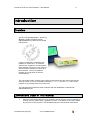
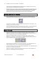
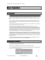
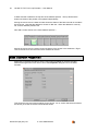
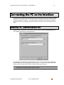
HOCHIKI TRUE LOOP EMULATOR USER MANUAL 2 Hochiki TE-TLE True Loop Emulator – User Manual If you have any queries regarding this product, or its functionality, please contact your nearest Hochiki office: Hochiki Europe (UK) Limited Grosvenor Road Gillingham Business Park Gillingham Kent ME8 0SA Tel: +44 (0) 1634 260133 Fax: +44 (0) 1634 260132 Web: http://www.hochikieurope.com Email: [email protected] Hochiki America Corporation 7051 Village Drive, Suite 100 Buena Park CA 90621-2268 Tel: +1-714-522-2246 Fax: +1-714-522-2268 Web: http://www.hochiki.com Email: [email protected] 2001-2004 Hochiki Europe (UK) Ltd. All rights reserved. No part of this document may be reproduced, stored in a retrieval system, or transmitted, in any form or by any means, without the prior permission in writing of Hochiki Europe (UK) Ltd. Hochiki Europe (UK) Limited reserves the right to alter the specifications of its products from time to time without notice. Although every effort has been made to ensure the accuracy of the information contained in this document it is not warranted or represented by Hochiki Europe (UK) Limited to be a complete and up-to-date description. Document Details: Title: Issue Issue Date Part No. Hochiki TE-TLE True Loop Emulator - User Manual 3.0 March 2004 2-3-0-416 This manual covers the TE-TLE software versions 1.00 - 2.02 Hochiki Europe (UK) Ltd 2-3-0-416/Mar04/Iss3 Hochiki TE-TLE True Loop Emulator – User Manual 3 Table of Contents Table of Contents 3 Introduction 5 Overview Conventions Used in This Manual Setting Up the Emulator Hardware TE-TLE True Loop Emulator Equipment List Equipment Included Equipment Required (not supplied) The Interface Switching the Interface On Interface RAM requirements 5 5 7 7 7 7 7 8 8 Connecting to the Computer Connecting to a Control Panel Polling Example Connections 9 9 9 10 Installing the Emulator Software 11 Requirements for the Computer Installing from the CD-ROM 11 11 Windows 2000 12 RAM Warning Message 12 Starting the Emulator Software 12 Using the True Loop Emulator Software Introduction Starting the Software for the First Time The Main Screen Areas Loop Display Creating Devices 13 13 13 14 15 15 Device Ranges Selecting a Device from Menu Selecting a Device from New Device window Device Type Families Removing Devices 15 16 17 18 18 Refresh Button Auto-Refresh Button 21 21 Changing Device States Device Properties Saving Configuration Data 23 Configuring Devices 25 Opening Configuration Data Hochiki Europe (UK) Ltd 19 20 25 2-3-0-416/Mar04/Iss3 4 Hochiki TE-TLE True Loop Emulator – User Manual Working with More than One Device at a Time Ramping the Analogue Value Setting Current Levels Setting Devices as 'Missing' Open Circuits Base Sounders 25 26 27 28 28 29 Introduction Adding Base Sounders Base Sounder Properties 29 29 30 Connecting the PC to the Interface 31 Selecting a PC Communications Port Running the Interface without a PC Global Commands 31 32 33 The Event Record 36 Polling Start & Polling Stop Events 36 Enable Data Log Functions 38 Examining the Event Record Saving the Event Record The Data Log Scripting 39 Introduction Working with Scripts 40 40 Index Hochiki Europe (UK) Ltd 37 37 37 42 2-3-0-416/Mar04/Iss3 Hochiki TE-TLE True Loop Emulator – User Manual 5 Introduction Overview The TE-TLE (Test Equipment - True Loop Emulator) system emulates Hochiki addressable devices that use the Hochiki ESP protocol. It uses a combination of hardware and software to achieve this. An Interface connects the computer to a control panel. Each Interface can run up to four loops of devices and the software can drive up to two Interfaces. Thus it is possible to emulate up to eight loops of devices simultaneously. The online Help system contains more extensive information than this manual and may be more up to date. It can be accessed by selecting Contents from the Help menu of the program or by pressing the F1 key at any time. This manual assumes that the reader is familiar with the capabilities of Hochiki ESP addressable devices. Conventions Used in This Manual When the manual describes text to be entered at the keyboard, keys to be pressed, or a series of menu options this typeface is used. For example, if the user is asked to press the 'Alt' key and the '3' key simultaneously the manual would show this as Hochiki Europe (UK) Ltd 2-3-0-416/Mar04/Iss3 6 Hochiki TE-TLE True Loop Emulator – User Manual Alt+3. Similarly, the menu options to display the Options window would be shown as File, Options. If a button or checkbox on screen is described, this will be shown thus: Save button, or Ramp checkbox. Hochiki Europe (UK) Ltd 2-3-0-416/Mar04/Iss3 Hochiki TE-TLE True Loop Emulator – User Manual 7 Setting Up the Emulator Hardware TE-TLE True Loop Emulator Equipment List Equipment Included The following items are supplied within the TE-TLE package. Please unpack the system and check that all of the following are included: True Loop Emulator module (box) Serial Cable (for connection to PC) Power Supply Unit (PSU) supplying an output of 12V DC from an input range of 190264V AC at 65mA - for use in Europe only. For USA, use PSU Model WP1112-760' supplying an output of 12V DC from an input range of 100 - 240V AC. Hochiki TE-TLE True Loop Emulator - User Manual (this manual) Hochiki TE-TLE True Loop Emulator - Software CD-ROM Equipment Required (not supplied) Wiring to connect the TE-TLE to a suitable control panel PC or laptop required to run the emulator software NOTE: The 3-pin plug supplied with the PSU is of the UK type. Please use an appropriate adapter if using the TE-TLE outside of the UK. Please ensure that only the supplied PSU (or the specified PSU for the USA, as above) is used with the TE-TLE. Hochiki Europe accepts no liability for damage caused by using any form of power supply other than that supplied or specified. The Interface The ‘Interface’ is the box or module that interfaces between the computer running the True Loop Emulator program and a Control Panel. However, it is more than just an electrical interface; it contains a microprocessor that carries out much of the processing of the system. The Interface has eight pairs of terminals grouped into four loops and eight LED's, one for each pair of terminals. The function of the LED's varies as described below. Hochiki Europe (UK) Ltd 2-3-0-416/Mar04/Iss3 8 Hochiki TE-TLE True Loop Emulator – User Manual LED Meaning Off Blinking On No voltage on loop Voltage & polling on loop Voltage but no polling Any changes that happen at the computer end are almost immediately mirrored at the Interface. However, if a large number of changes are required at the same time (for instance, lots of devices added at the same time), then there may be a small delay before all the information is transmitted to the Interface. In this case, a message is shown in the bottom status bar of “Downloading device status…”. Also on the front panel there is an RS-232 9-way D-type (DB9) connector to connect with a computer, a socket for power with a Power LED and an earth stud. NOTE: To comply with EMC regulations the Interface must be connected to a suitable earthing source. The earth stud is provided on the front panel for this purpose. Switching the Interface On When the mains power supply is plugged in and connected to the Interface, it starts up and runs some internal diagnostics. While in this state, the Power LED is off and the other LED's scan left and right. The Loop Terminals are set to Open Circuit and do not generate any current responses. Interface RAM requirements To run the TE-TLE software version 2.0 or later requires at least 4 megabits of RAM memory to be present within the interface. If the interface has less RAM than this you will be presented with a warning on-screen informing you of this the first time you run the software. This warning is shown in the status bar above the Start Button in Windows: You can double-click here to display a page within the software's help files explaining further. As a guide, any interfaces produced by Hochiki Europe with 'cream' coloured cases will most likely not have the extended RAM capacity. In this instance you can return your interface to either Hochiki Europe (UK) Ltd or Hochiki America Corporation who will undertake to increase the RAM memory FREE OF CHARGE. Please contact your local Hochiki office for further details (see page 2 for contact details). Hochiki Europe (UK) Ltd 2-3-0-416/Mar04/Iss3 Hochiki TE-TLE True Loop Emulator – User Manual 9 Interface RAM Compatible Software Version CREAM coloured case 1 megabit 1.0 only (but can be upgraded) GREY coloured case 4 megabit 1.0 to 2.01 Connecting to the Computer The computer and Interface are connected by a serial RS-232 ("straight") cable between the 9-way D-type connector on the Interface to a serial port on the computer. The True Loop Emulator must be informed as to which serial port is being used. The PC Communications property page of the Options dialogue box (from File, Options) is used to accomplish this (see "Connecting the PC to the Interface" on page 31. Connecting to a Control Panel The Interface contains an electrical interface for four loops. Each loop consists of a pair of Drive terminals (+ and -) and a pair of Return terminals (+ and -). Each loop is isolated from the others. When a loop is set to be Open Circuit, the Drive and Return sections are isolated from each other. When a loop is set with no Open Circuits, the Drive and Return sections are directly connected to each other. The Drive terminals of a loop from the Control Panel should be connected to the Drive terminals of a loop on the Interface. The Return terminals on the Interface should be connected to the Return terminals of the same loop on the Control Panel. NOTE: Always ensure the loop polarity at the Interface is correct, as indicated by the + and labelling. When a Control Panel has been connected to the appropriate terminals on the Interface and has been switched on, the LED's indicate voltage and polling information for each loop. Polling As the Control Panel polls each address, the computer loop display for that address ‘blinks’ (unless this has been turned off in the Options dialogue box) and a summary of polling is shown in the bottom status bar. Some Control Panel commands apply to a range of addresses; these are indicated by all relevant addresses ‘blinking’ at the same time. Hochiki Europe (UK) Ltd 2-3-0-416/Mar04/Iss3 10 Hochiki TE-TLE True Loop Emulator – User Manual Example Connections The following diagram shows how the Interface should be connected to a PC and a Fire Alarm Control Panel: Hochiki Europe (UK) Ltd 2-3-0-416/Mar04/Iss3 Hochiki TE-TLE True Loop Emulator – User Manual 11 Installing the Emulator Software Requirements for the Computer The table below shows both the minimum and the recommended specification for the computer that is going to be used: Processor Operating System Hard disk Screen Resolution Connections Minimum Recommended Pentium 90 Windows 95, 98, NT4, XPhome or 2000 Professional 5 Mbytes free 800 x 600 pixels 16 colours 1 serial port per interface Pentium 200 or faster Windows 95 or above 5 Mbytes free 1024 x 768 pixels or more 256 colours 1 serial port per interface Mouse NOTE: The software is very display-orientated. Use the highest screen resolution available and use the software full-screen (“maximised”) if possible. Installing from the CD-ROM Insert the True Loop Emulator CD-ROM. If “auto insert notification” is enabled, the installation program will automatically start. If nothing has happened within thirty seconds after inserting the CD-ROM, then run the installation program called “SETUP.EXE” that is on the CD-ROM. This can be done by selecting the Run menu item on the Start Menu, then typing D:\SETUP.EXE (replacing the D with the drive letter of your CD-ROM drive if necessary) and pressing the Enter key. Alternatively, Use Windows Explorer to explore the contents of the CD and double-click the SETUP.EXE file. Once the installation program starts, it asks for confirmation that you wish to install the True Loop Emulator software. Once you have selected Yes, just follow the on-screen instructions. On completing the installation, you are given the opportunity to start the Software immediately. NOTE: The software does not run on Windows 3.x or Windows for Workgroups. Hochiki Europe (UK) Ltd 2-3-0-416/Mar04/Iss3 12 Hochiki TE-TLE True Loop Emulator – User Manual Windows 2000 Depending on configuration of your system, the software may need to be installed under an "Administrator" as well as a "User" profile. Starting the Emulator Software The True Loop Emulator software can be started by selecting the True Loop Emulator menu item in the Programs section of the Start Menu. If the installation used the default settings, this menu item will be in a sub-menu called Hochiki. Alternatively, once you have saved a configuration data file, you can start the software by double clicking on the configuration data file. The on-line Help documents several other ways to start the software (search for Start), but the Start Menu method will do for now. RAM Warning Message To run the TE-TLE software version 2.0 or later requires at least 4 megabits of RAM memory to be present within the interface. If the interface has less RAM than this you will be presented with a warning on-screen informing you of this the first time you run the software (see "Interface RAM requirements" on page 8). Hochiki Europe (UK) Ltd 2-3-0-416/Mar04/Iss3 Hochiki TE-TLE True Loop Emulator – User Manual 13 Using the True Loop Emulator Software Introduction This chapter is a step-by-step guide on how to use the Emulator Software for the first time. It covers starting and configuring the software and briefly describes some of the main areas of the system. These instructions can be followed without the Interface being connected to the computer, so for the time being please disconnect the serial cable from the PC. Starting the Software for the First Time If the software is not already running, select Loop Emulator from the entry in the Programs menu from the Start button. By default, this will be on the Hochiki sub-menu, but it may have been installed elsewhere. The software displays a “Welcome” message when is started for the first time: For now, just click on the OK button. The main window can now be seen. Hochiki Europe (UK) Ltd 2-3-0-416/Mar04/Iss3 14 Hochiki TE-TLE True Loop Emulator – User Manual The Main Screen Areas When the program first starts, the main window looks similar that shown below: There are two rows of tool buttons underneath the row of menu options. These icons are short cuts to the most common functions of the Emulator: These button and their functions will be described in more detail later on in this manual. If the screen resolution of the computer is less than 1024 by 768 pixels, the buttons may take seem too large in proportion to the main screen. They may be reduced in size by removing the caption or by using smaller pictures on the buttons. Right-click on any button to obtain a button-size menu or use the Display property page of the Options dialogue box from File menu (see "Display Options" on page 16). There is also a row of tabs below the buttons: Hochiki Europe (UK) Ltd 2-3-0-416/Mar04/Iss3 Hochiki TE-TLE True Loop Emulator – User Manual 15 These select different pages for the rest of the window. There are eight pages for loops, one for the Event Record and one for Scripts. The tab for the page that is currently displayed is shown as being in front of the others. Loop Display Each loop tab displays a page for a loop. The True Loop Emulator can emulate up to eight loops. The loop display consists of 127 address positions, a ‘global’ position and two status bars above and below the address positions. Move the mouse over the address positions and watch the top status bar. The status bar contains the loop number and address of the position that the mouse is over. Later on, this status bar will contain further information on the device that is at this address. Most of the buttons are enabled while a loop is displayed, although some are currently disabled. The New, Open, Save and Print buttons are the standard Windows buttons. The buttons that have pictures of different devices are called the Device Buttons. These are used to put emulated devices at addresses. Your system may have different device buttons to those shown in the pictures in this manual. Creating Devices The Emulator software allows the user to select and position icons that represent various fire detection devices. Device Ranges The range of devices available from the device drop-down lists on the main screen is dependent on the Devices setting. As default, the devices initially available are in line with the country code of the host PC. Hochiki Europe devices, Hochiki America devices or a combination of both can be selected. This is achieved from the Display tab on the Options dialogue window (File, Options): Hochiki Europe (UK) Ltd 2-3-0-416/Mar04/Iss3 16 Hochiki TE-TLE True Loop Emulator – User Manual Display Options Checking the "Hochiki America Corporation" checkbox in the Devices section will result in only Hochiki America devices being available for selection, and vice versa, checking the "Hochiki Europe (UK) Ltd" checkbox will result in only Hochiki Europe devices being available. Checking both checkboxes here will result in both product ranges being available. Selecting a Device from Menu Move the mouse over the first device button and then wait until a ‘tip’ appears. This describes the device in more detail. If this device is not an analogue smoke or heat sensor on your system, choose another button. Click on this button and move the mouse over an address position, in this example we will use address number 72. Notice that the mouse pointer has changed into the shape of the device. Now click on address position 72. A picture of the device is drawn at the address position with a green background and a dark blue outline. The True Loop Emulator is now emulating a device at address 72 on loop 1. The green background indicates that the device is in a ‘normal’ state. The dark blue outline indicates Hochiki Europe (UK) Ltd 2-3-0-416/Mar04/Iss3 Hochiki TE-TLE True Loop Emulator – User Manual 17 that the address position is currently ‘selected’. The top status bar now has more information in it: The mouse pointer is still the picture of the device and it can be used to put the same type of device at other addresses on this loop. Selecting a Device from New Device window You can also add a new device by right-clicking with the mouse on one of the grid squares and selecting New Device from the pop-up menu. The New Device dialogue box will be displayed. Click on New Device to display a device ‘tree’. You can select any device from here; each range of devices is shown as a branch similar to Windows Explorer. Each branch can be expanded or collapsed using the plus and minus symbols: Highlight the device and click on the OK button to add this device to the grid. Hochiki Europe (UK) Ltd 2-3-0-416/Mar04/Iss3 18 Hochiki TE-TLE True Loop Emulator – User Manual Device Type Families Some Device Buttons have an arrow on their right-hand side. This indicates that there is a ‘family’ of device types and that the button shows just one member from the family. For example, click on the arrow to the side of the Callpoint button, to see the drop-down list of device types: Click on an item in the list to change the picture on the device button. Now use this to add a device at another address; for example address number 18. Removing Devices If for any reason you place a device at the wrong address, simply follow these steps to remove it: Change the mouse shape back to the pointer by clicking on the Pointer button (white arrow). Click on the device address you wish to remove so that it is highlighted with the blue lines. Click on the Delete button - the device icon will disappear from the Address Square denoting the device has been removed from the loop. Other ways to delete selected devices are Press the Delete key on the keyboard whilst device is highlighted Select Delete from the Edit menu or Device menu whilst device is highlighted Select Delete from the Properties pop-up menu when right-mouse clicking the device. Hochiki Europe (UK) Ltd 2-3-0-416/Mar04/Iss3 Hochiki TE-TLE True Loop Emulator – User Manual 19 Select No Device from the New Device option from the Properties menu when right-mouse clicking the device. Changing Device States Now look at the buttons that have arrows in different colours: These are used to set devices into different ‘states’. A device can be in alarm if it has an analogue channel or input channel. A device can be in pre-alarm if it is not in alarm and has an analogue channel. A device can be in a fault state if it is not in alarm or pre-alarm and if it has a fault on an input channel, an output channel or a ‘primary-side’ fault. A device is in a normal state if it is not in alarm, in pre-alarm and does not have a fault. The Missing state is described in the next chapter. Click on the Alarm button (red arrow) and move the mouse over the address positions. Note that the mouse pointer changes to a red arrow. NOTE: If you have difficulty in distinguishing colours, you may wish to change the mouse pointers to those that also display a letter next to them. This can be done on the Display tab of the Options dialogue box from File, Options see "Display Options" on page 16). Now click on the device at address position 72. It changes to a pink background and the status bar now indicates that the device is in alarm. If there was an Interface connected to the computer and a Control Panel connected to the Interface, the Control Panel would now be indicating an alarm condition. Next, right-click on the device at address position 72. NOTE: With the mouse pointer over the address position, depress the right-hand button on the mouse. Keyboard equivalents are the Windows Menu key and SHIFT+F10. A context-sensitive menu appears: Hochiki Europe (UK) Ltd 2-3-0-416/Mar04/Iss3 20 Hochiki TE-TLE True Loop Emulator – User Manual This is a sub-set of the menu items on the Device menu. Only those items that are appropriate are shown. Select the Normal menu item to change the device back to the ‘Normal’ state. Device Properties Right-click again on address 72 and pick the Properties menu item. This displays a dialogue box that has the properties for the device shown on various pages: The tabs across the top of the dialogue box access the different pages here. Each device type will have different pages, appropriate to the capabilities of that device. The device shown above has a page for one analogue channel, for output channels, for the EEPROM contents, for the device faults and for the interrupt status of the device. The analogue page shows various values in decimal, hexadecimal and in calibrated units. The user can change the decimal forms of some of these. Hochiki Europe (UK) Ltd 2-3-0-416/Mar04/Iss3 Hochiki TE-TLE True Loop Emulator – User Manual 21 The Control Panel would normally set the Zero Point and Variable Threshold. The user can change the current Analogue Value and the Fire Point. Refresh Button If the Control Panel (or a Script or Ramping - see later sections in this Manual) changes a device’s properties, those properties are not automatically updated in this dialogue box. Instead, the Refresh button at the bottom of the screen is enabled: Clicking on this updates all the properties on the dialogue box to match those of the current device. Auto-Refresh Button This button is a toggle button that stays down or up when clicked. When it is down, the dialogue box automatically updates all the device properties whenever a Control Panel, a Script or Ramping changes the properties of the devices. Click on the Output tab to show the Output properties for this device: This particular device type has only one output channel. This channel controls the LED's and is not currently activated by the control panel. The picture to the right shows how the device will look on the screen if the LED's are activated. Some device types have monitored outputs and can have their outputs activated continuously or intermittently. Below is the property page for such a device: Hochiki Europe (UK) Ltd 2-3-0-416/Mar04/Iss3 22 Hochiki TE-TLE True Loop Emulator – User Manual The user can generate faults on the monitored outputs and see exactly how the outputs are activated. Now close the Device Properties box for this device and display the Device Properties dialogue box for the device at address 18. This device has one input channel that is used to indicate the state of the break glass. The user can set whether this input is active or not. The picture to the right shows how the device will look on the screen if the break glass is activated. Some device types have monitored inputs. Below is the property page for such a device: Hochiki Europe (UK) Ltd 2-3-0-416/Mar04/Iss3 Hochiki TE-TLE True Loop Emulator – User Manual 23 The user can generate a fault on the monitored input, in addition to activating it. Saving Configuration Data Click on the Save button to display the Save Configuration Data dialogue box. NOTE: The Save button has a different function if the Event records or Script pages is displayed. In this case, entries on the File menu can be used to save configuration data. Choose an appropriate location and file name and save the data. This will create a file that contains a list of all address positions and what devices are at those addresses. It does not contain the state of the devices. The saved file will have an extension of ".hle". Hochiki Europe (UK) Ltd 2-3-0-416/Mar04/Iss3 24 Hochiki TE-TLE True Loop Emulator – User Manual This page is intentionally blank. Hochiki Europe (UK) Ltd 2-3-0-416/Mar04/Iss3 Hochiki TE-TLE True Loop Emulator – User Manual 25 Configuring Devices This chapter assumes that you have just completed the operation in the previous chapter. If not, quickly go through it again, in order to set up the True Loop Emulator system in the way that this chapter expects. It still assumes that the Interface is not yet connected to the computer, so ensure the serial cable is disconnected from the PC at this point. Opening Configuration Data Click on the Open button to display the Open Configuration Data dialogue box. NOTE: The Open button has a different function if the Event Record or Script pages are displayed. In this case, entries on the File menu can be used to open configuration data. Choose the file name that was used at the end of the previous chapter and open the data. This will put devices in address positions as specified by the file. All devices are set to ‘Normal’. Working with More than One Device at a Time Click on the Pointer button (white arrow) if it is not already depressed. Now click on address position 1. While holding down the Ctrl key, click on address positions 3 and 5. Note that all three address positions have a dark blue outline that indicates they are ‘selected’ simultaneously. Now click on a device button to change the mouse pointer to a device. Use this to click in one of the addresses 1, 3 or 5. Note how all of the selected addresses now contain the device. Applying an operation to one of the selected address positions automatically applies to it to the others whenever multiple address positions are selected. Hochiki Europe (UK) Ltd 2-3-0-416/Mar04/Iss3 26 Hochiki TE-TLE True Loop Emulator – User Manual There are menu items on the Edit menu to select all address positions (Select All), to ‘un-select’ all address positions (Select None) and to selectively select or un-select groups of addresses (Select Some). It is also possible to select a range of addresses by clicking on the first address position then, while holding down the Shift key, click on the last address position. NOTE: You need to revert to the white arrow mouse pointer (by clicking on the Pointer button) to change the selection without affecting the state of devices and address positions. Ramping the Analogue Value Select address position 72 only. This should have a device in it that has an analogue channel. Display the Device Properties dialogue box for this device. Click on the Set to Normal button, just to make sure all properties have their default values. Now click on the Ramp checkbox. This enables several new properties that can be changed by the user. These are used to command the True Loop Emulator to change the analogue value of a device over time. The first value (labelled ‘to’ in the dialogue box) is the ‘target’ value. The analogue value will change from the current analogue value to the target analogue value. The change happens in steps; the rate at which it does this is determined by the two values labelled ‘at’ and ‘per’. The ‘at’ value determines the step height; this is in analogue value units. The ‘per’ value determines the step width; this is in seconds. Hochiki Europe (UK) Ltd 2-3-0-416/Mar04/Iss3 Hochiki TE-TLE True Loop Emulator – User Manual 27 Change the ramp settings to ramp from 61 to 200 at 10 per 5 seconds and then click on the OK button. Move the mouse pointer over address 72 and watch the analogue value change in the status bar at the top. The analogue value will rise until it reaches the programmed value (200 in this instance) and the device will then enter into Pre-Alarm and then into Alarm as it reaches the threshold. Setting Current Levels Right-click on address position 72 and highlight the Current Level menu item. Hochiki Europe (UK) Ltd 2-3-0-416/Mar04/Iss3 28 Hochiki TE-TLE True Loop Emulator – User Manual The sub-menu that is displayed shows the level of current, in milliamps, that the Interface uses to respond to commands from a Control Panel. The Nominal level is the one that is usually used and corresponds to the typical value of real devices. The Minimum and Maximum levels are the limits of the ESP (Enhanced Systems Protocol) specification and can be used to test Control Panel compliance. The Double Address level is used to emulate two identical devices set to the same address. Setting Devices as 'Missing' Click on the Missing button (blue arrow). Now use this to click on address position 72. Note that the picture of the device now has a grey background and a blue line through it. This device is now ‘Missing’. It does not respond to commands from a Control Panel. This emulates a ‘sensor-removed’ condition. Click on the address position again and see that the device returns. At this point, the device has its ‘power-on’ flag set and requires the Control Panel to re-initialise the device. Open Circuits Right-click on address position 71 and select the Create Open Circuit before address 71 menu item. A vertical yellow bar is displayed between address positions 70 and 71 to indicate that an open circuit is being emulated here. Right-click on address position 73 and select the Create Open Circuit after address 73 menu item. A vertical yellow bar is displayed between address positions 73 and 74 to indicate an open circuit is being emulated here. Note that the device at address 72 is now shown as ‘Missing’. This is because there is an open circuit either side of it; thus, it cannot be reached by a Control Panel. Try using the Missing mouse tool to set the device to ‘Not Missing’. It is not allowed because the open circuit conditions are still present. Right-click on address 73 and select the Remove Open Circuit after address 73 menu item. Note that the device has now returned. Hochiki Europe (UK) Ltd 2-3-0-416/Mar04/Iss3 Hochiki TE-TLE True Loop Emulator – User Manual 29 Base Sounders Introduction NOTE: This section is not currently applicable to Hochiki America Device users. Most Hochiki ESP addressable devices have addresses that are set in the range 1 to 127. Base Sounders are different in that their address can be in the range 1 to 254, or not set at all. For the purposes of the True Loop Emulator, Base Sounders that have addresses in the range 1 to 127 are defined as a different device type called Wall Sounders and are treated as any other device. Base Sounders usually have a sensor connected to them. If their address has not been set, they cannot be used until one is connected. The Loop Display only has address positions for address numbers 1 to 127. When addresses in the range 128 to 254 are needed, the top third of the address position that is 127 less is used. Base Sounders are the only devices that can co-exist with another device at an address position in the emulator. If there is both an Optical Smoke sensor and a Base Sounder at address position 1, for instance, then the smoke sensor has address 1 and the base sounder has address 128 or 'Not Set' if it has not yet been set. Two different forms of Base Sounder are implemented in the True Loop Emulator. The Preaddressed Base Sounder corresponds to a Base Sounder that has already had address set in the range 128 to 254. The Base Sounder corresponds to a device that has not yet had its address set; this is the device type that would more commonly used, as it is how the device leaves the factory. All of these devices are grouped within one Device Family and are available from the drop down list accessed via the arrow to the side of the Base button. Adding Base Sounders This chapter assumes that the Interface is not yet connected to the computer, so ensure that the serial cable is disconnected at this stage. If necessary, use the New button to clear any existing configuration data. Click on the Base device button (not the Pre-addressed Base Sounder or the Wall Sounder). Use this to click on address position 1. Hochiki Europe (UK) Ltd 2-3-0-416/Mar04/Iss3 30 Hochiki TE-TLE True Loop Emulator – User Manual A Base Sounder is added to the top third of the address position. The top third and the bottom two-thirds of the position now operate independently. Moving the mouse over the base sounder shows the status of the base sounder in the status bar at the top. Note that the address is shown as 'Not Set'. When the address is correctly set, it will be address position 128. Now add a smoke sensor to the same address position 1. Moving the mouse over the sensor shows the status of the sensor in the status bar. Rightclick on the sensor to see the menu items available for sensor. Base Sounder Properties Right-click on the base sounder to see the menu items available for the base sounder. Select the Properties menu item to show the Properties dialogue box for the Base Sounder. This shows the tone and volume settings for the device. As no Control Panel has accessed the device yet, these are all set to their default values. Hochiki Europe (UK) Ltd 2-3-0-416/Mar04/Iss3 Hochiki TE-TLE True Loop Emulator – User Manual 31 Connecting the PC to the Interface Once the user is familiar with the software and its functionality, the PC running the software should be reconnected to the Interface with the serial cable as explained in "Setting Up the Emulator Hardware" on page 7. Once this has been completed, the software connection set-up will need to be configured so that the Interface and PC can communicate with each other. Selecting a PC Communications Port Take the File, Options menu options, and then select the PC Communications tab. The software will display the following screen: The software can handle one or two Interfaces. It does this by employing two COM ports. Each of these ports can be assigned to a set of loops, 1 - 4 and 5 - 8. Use the drop down windows here to select either COM1 or COM2 for each range of loops. NOTE: If a second interface is NOT fitted (Loops 5 to 8) a connection should NOT be specified, in other words left as “Not Connected”. Hochiki Europe (UK) Ltd 2-3-0-416/Mar04/Iss3 32 Hochiki TE-TLE True Loop Emulator – User Manual NOTE: A different setting should be selected for each range of loops - they should not be set to the same COM number. The software will display a warning to this effect if you attempt this. Click the OK button when this has been completed. The program that is run in the Interface is downloaded from the computer. Thus, a message is sometimes displayed in the bottom status bar showing “Updating software in Interface…” or “Updating Device Characteristics in Interface…”. Once the PC running the True Loop Emulator software has established communications with the Interface and updated it if necessary, the Power LED on the Interface is turned on. Also, the device and open circuit information is sent from the computer to the Interface and the LED's switch to their usual function (see "Switching the Interface On" on page 8"). Running the Interface without a PC Once the software has been used to configure the Interface, the PC can be removed, leaving the Interface running with the Control Panel. In this scenario the connection would be as follows: Please note that the following conditions apply when operating the True Loop Emulator system is this way: The Interface will not be able to run Scripts on its own. The Interface must have a constant supply of power. If the power supply is interrupted, the Interface will lose the settings it has been programmed with, the PC will need to be reconnected, and the Interface re-configured. The Interface cannot store any data and therefore the PC cannot be reconnected to retrieve events or data logs that occurred whilst it was disconnected. The analogue ramping function does not work without the PC connected. Hochiki Europe (UK) Ltd 2-3-0-416/Mar04/Iss3 Hochiki TE-TLE True Loop Emulator – User Manual 33 The Interface can be left connected indefinitely. This is particularly useful in a multipanel or multi-loop scenario, where several panels/loops may need soak testing simultaneously. Global Commands Some control panel commands apply to all addresses on a loop. The most recent global command is indicated in the Global position (before address position 1) at the top left of the Loop display screen. An icon is shown here for each type of global command and more details can be seen in the top status bar by holding the mouse over the icon in the Global position. Global Command Icons The various icons shown in the Global position of the main Loop display screen are explained below: Hochiki Europe (UK) Ltd 2-3-0-416/Mar04/Iss3 34 Hochiki TE-TLE True Loop Emulator – User Manual Interrupt Level Check This Icon will be displayed when a device creates an interrupt on the system. Sleep Mode Activate This Icon will be displayed when the system is in sleep mode (low power mode). Synchronise On This Icon will be displayed when the system sends a synchronisation on signal to outputs (for example sounder devices). Synchronise Off This Icon will be displayed when the system sends a synchronisation off signal to outputs (for example sounder devices). Hochiki Europe (UK) Ltd 2-3-0-416/Mar04/Iss3 Hochiki TE-TLE True Loop Emulator – User Manual 35 A/D Conversion This Icon will be displayed every one second (approx.) indicating that the devices are performing their analogue to digital conversions. Fire Indicator Synchronisation This Icon will be displayed when the control panel synchronises the fire indicator LEDs. Interrupt Disable This Icon will be displayed when the system disables interrupts to allow certain actions to take place, for example a fire test. Interrupt Disable Cancellation This Icon will be displayed when the system interrupts have been re-enabled after a disablement. Global Find Address This Icon will be displayed when the system is initialising the loop to establish the presence of base sounders. Global Output This Icon will be displayed when multiple outputs are operated by the control panel. Hochiki Europe (UK) Ltd 2-3-0-416/Mar04/Iss3 36 Hochiki TE-TLE True Loop Emulator – User Manual The Event Record The Event Record stores all events that happen in the True Loop Emulator system. These include both events generated by the user at the computer and events generated by the Control Panel. The Event Record is always running and its capability is only limited by the amount of memory on the computer; it can usually store 32,000 events. The online Help system contains a complete list of events that can be generated and their meaning (Search for 'Event Summary'). Polling Start & Polling Stop Events To reduce the amount of event data recorded in the Event Record, you can specify whether start and stop events are added to the record or ignored. To do this take the File, Options menu options to display the Options dialogue window. Select the Display tab: Check or uncheck the Record Polling Start/Stop checkbox to specify how these events are recorded. Hochiki Europe (UK) Ltd 2-3-0-416/Mar04/Iss3 Hochiki TE-TLE True Loop Emulator – User Manual 37 Examining the Event Record The Event Record is displayed when the Event Record tab is clicked on the main window. A grid is shown with columns for the date & time of the event, the loop, the addresses, the device type and the event itself. A description of the event is displayed on right clicking on an event in the grid and selecting the What’s This? menu item. An event can be ‘selected’ by clicking in the grey margin to the left of an event. More sophisticated selection can be carried out using the Select Some menu item on the Edit menu. Selected events can be copied to the PC's clipboard using the Copy button or the Copy menu item on the Edit menu. Saving the Event Record The event record can be saved in a format that can be opened by other programs (for example Microsoft Excel). Click on the Save button to choose the file name and location. Either all the events or just the selected ones can be saved. The saved file will have a ".log" extension and is a text file type format. The Data Log The Data Log is separate from the Event Record. It is used to log all ESP (Enhanced System Protocol®) commands from the Control Panel and all responses from the Interface. This data is particularly useful to panel manufacturers and developers. Access to this function of the TE-TLE is restricted by a password. This password is available from Hochiki Europe (UK) Ltd only to third parties that have previously signed the Hochiki Europe (UK) Confidentiality Agreement in relation to the ESP (Enhanced System Protocol®). If you feel Hochiki Europe (UK) Ltd 2-3-0-416/Mar04/Iss3 38 Hochiki TE-TLE True Loop Emulator – User Manual you should have this password please contact Hochiki Europe (UK) Ltd ([email protected]). Enable Data Log Functions To enable this functionality select the File, Options menu options to display the Options dialogue window and then select the Panel Communications tab: Check the Enable Data Log functions checkbox and a new field will be displayed, Password. Enter the password as supplied by Hochiki Europe (UK) Ltd or Hochiki America Corporation. Once this has been accepted three sub-options from the Events menu option will be enabled. These are Start Data Logging, Stop Data Logging and Save data log As.... The Data Log is not always running; it is started and stopped by these commands on the Events menu. The Log can store 1,000,000 command/response pairs. After this, older data is deleted to make room as new data is generated. Hochiki Europe (UK) Ltd 2-3-0-416/Mar04/Iss3 Hochiki TE-TLE True Loop Emulator – User Manual 39 When the data log has been stopped and there is data in it (the Control Panel has sent some commands), it can be saved as a text file for further processing using the Save data log As... command. See the online Help for more details of the file format (search for 'Data Log Format'). This page is intentionally blank. Hochiki Europe (UK) Ltd 2-3-0-416/Mar04/Iss3 40 Hochiki TE-TLE True Loop Emulator – User Manual Scripting Introduction Scripting is an advanced topic and should probably be left until you are familiar with other aspects of the True Loop Emulator. A script is a list of commands that will be executed by the True Loop Emulator. The commands are written in a language that is very similar to the BASIC computer language. This language is quite easy to learn; there are many books available. The extensions to the language to make it appropriate for the True Loop Emulator are covered in the online Help system (Search for 'Script Command' and 'Script Constants'). There are several sample scripts in the Help system that illustrate techniques and features of scripting (Search for 'Example'). Also available is the "TE-TLE True Loop Emulator Software Script Guide (Part Number 2-3-0-460) which details all of the script commands used in the Emulator software. Please contact Hochiki Europe (UK) Ltd for a copy of this document. Working with Scripts Scripts can be displayed by clicking on the Script tab of the main window. This gives a large area in which to type and edit a script. A script can be generated by Typing one in. Opening a script file (Open button or Open menu item on Script menu). Pasting one in from the clipboard (for instance, an example copied there from the Script Examples). Translating selected events from the Event Record using the Events button (search for 'Convert Events' in the online Help). The script can be saved and printed by using the standard buttons or the menu items on the Script menu. The script can be started and stopped by using the Run and Stop buttons or the menu items on the Script menu. Hochiki Europe (UK) Ltd 2-3-0-416/Mar04/Iss3 Hochiki TE-TLE True Loop Emulator – User Manual 41 NOTE: See the on-line help system within the True Loop Emulator software for detailed information regarding Scripts. Or alternatively, see the "TE-TLE True Loop Emulator - Software Script Guide" (Part Number 2-3-0-460). Hochiki Europe (UK) Ltd 2-3-0-416/Mar04/Iss3 42 Hochiki TE-TLE True Loop Emulator – User Manual Index If you cannot find the information you require in this manual, try the software Help system. A Address position Alarm Analogue Value F 15 18, 27 20 B Base Sounders Button 29 14 C Clipboard COM Port Connections Control Panel Conventions Copy Current Level 36 8 11 7, 20 6 36 27 36 15 20 19 20 15 28 8 E EEPROM Event Record Example G Global command 20 35, 38 38 Hard disk Help 33 11 6 I Installation Interface Interrupt status 11 6, 7 20 L LED Loop Terminals 7 8 M Main Window Maximum Minimum Missing 14 27 27 28 N New Nominal Hochiki Europe (UK) Ltd 17 18 15 20 H D Data Log Device Buttons Device faults Device Menu Device Properties Display Property Page Double Address Drive Family Fault File Menu Fire Point 2-3-0-416/Mar04/Iss3 29 27 Hochiki TE-TLE True Loop Emulator – User Manual Normal Not Set 16, 19, 25 29 O Open Open Circuits Operating System Optically isolated Options Dialogue Box 25 28 11 9 15 P Poll Power LED Power supply Pre-addressed Base Sounder Pre-Alarm Processor Properties 9 8 8 29 18, 27 11 20 R Ramp Rate Refresh Requirements Return RS-232 Hochiki Europe (UK) Ltd Screen resolution Script Serial port Specification State Status bar 20, 26 26 20 11 8 8 11, 15 20, 38 8, 11 11 18 15 T Tab Target Terminal Tone 15 26 7 30 U Updating 31 V Variable Threshold Volume 20 30 W Wall Sounders Welcome 29 13 Z S Sample Save 43 38 24, 36 Zero Point 2-3-0-416/Mar04/Iss3 20