1
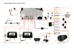
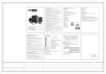
Vibrator Massage & Heat
Installation Manual
[8 FUNCTION & 6 Motors)
R
AKEE INDUSTRIAL CO.,LTD.
Agent
Motor Placement-Chair
M1&M2 (Back)
Heat Pad
M3&4 (Waist)
M5&6 (Seat)
[註:馬達裝配位置可依個人需求自行調整]
Motor Cavity Cutout Template
2 1/4 "
2"
Massage System Parts List
M5
Heat Pad
M6
FUNCTION
2
3
15
30 min
4
5
6
7
8
Heat
1
SPEED
FUNCTION
ON/OFF
41
40
POWER
H/T
TIMER
31
30
20
11
10
P/W
21
M4
M3
M2
M1
Connect Box
Plug
Fuse
TO: Car Battery
Red Line:
Black Line :
+
Parts List
-
1.Motor set 6 pcs
2.Controler 1 pcs
3.Power wire 1 pcs
4.Connect box
5.Heat pad
1 pcs
1 pcs
How To Operator The Massage Controller
FUNCTION
1
2
3
4
15
30 min
5
6
7
8
Heat
1.LED Time Indicator-Shows the time 15/30
2.Power Button-Turns the power on and off.
3.Time setting Button-Press this button to
select the action period of 15/30 Minutes.
4.Function Button-Selects any of the nine (8)
programs manually.
5.function Indicator-Indicates whether using
the autmatic or the manual mode of selection.
6.Speed Button-Controls the intensity of the
massage action in all modes. There are
Five (5) speeds that can be selected .The
chair always begin at the middle intensity
When the power is turned on.
7.Heat switch-turns the heater on and off.
SPEED
FUNCTION
ON/OFF
TIMER
POWER
Important Safety Instructions
When using an electrical appliance, basic precautions should
always be Followed, Including the followed: Read all instructions
before using this appliance.
DANGER - To reduce the risk of electric shock:
1.Always unplugs this appliance from electrical out let immediately after using and before cleaning.
2.Do not reach for an appliance that has fallen into water. Unplug
immediately.
3.Do not place or store appliance where it can fall or be pulled into
a tub or sink.
4.Do not place in or drop into water or other liquid.
WARNING - To reduce the risk, burns fire electric shock, or injury
to persons:
1.An appliance should never be left unattended when plugged in,
unplug from outlet When not in use. And before putting on or
taking off parts.
2.Do not operate under blanket or pillow, excessive heating can
occur cause fire, electric shock, or injury to persons.
3.Use this appliance only for this intended use as described in
this in this manual.
4.Never operate this appliance if it has a damaged cord or plug,
if it is not working properly, if it has been dropped or damaged,
or dropped in to water.
5. Do not carry this appliance by supply cord or use cord as a handle.
6. Keep the cord away from heated surfaces.
7. Never drop or insert any into this product.
8. Do not use outdoors.
9.To disconnect, turn alt controls to the OFF position, then remove
plug from outlet.
Wiring Placement
Route the wirce down the seat back and pass them to the rear of
the bottom seat cover. Cut an entry hole at the rear of the bottom
seat cover and pass the wire harncss throuth or tuck the harness
around the rear of the seat cushion. Attach the contoller box to the
seat frame components with tie wraps and connect all wiring and
the controller wand. Bundle up and organize the loose wiring with
tie wraps as shown below.
Bottm Foam
Back Foam
Attach to
Seat Frame
Components
Connect Box
Wire Harness
System Power Connection
Power Connection To Vehicle
1.Run the power harness under the carpet and along the scuff plate
toward the fuse box.
2.Install the negative wire to the OEM ground screw and secure in
place.
3.Connect the red wire(positive)to the power seat mechanism power
wire.
Fuse Box
Ground
Connect Box
Harness Extension
Fuse
Fuse Box Wiring
Motor Installation Foam
(A.) Foam Cutout:
Cut out the foam to receive the shape of the motor housing by pulling back the
long cut of the foam and placing the blade on an angle and cut towards the center. Repeat this on the other side and remove the foam cutout .
2"
1"
Cross Section Of Foam
(B.)Verify that all motors are operational before Gluing:
Gluing Motors:
Using spray gluc, apply into the foam cavity and then place motor into foam
cavity and gently pull the motor wires to insure a light fit, Apply pressure to the
top of motors and hold against the foam for 15 seconds.
MOTOR
Apply glue in these areas
Apply glue in these areas
Do not spray glue on the motor or motor plate
(C.)Needle Punch Application
The Photo below shows the final installation of the needle punch
on the set bottom
1/4"Foam If Required
Glue
MOTOR
Cross Section Of Foam