1
MELSEC iQ-F
FX5 User's Manual (SLMP)
SAFETY PRECAUTIONS
(Read these precautions before use.)
Before using this product, please read this manual and the relevant manuals introduced in this manual carefully and pay full
attention to safety in order to handle the product correctly.
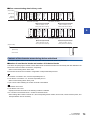
This manual classifies the safety precautions into two categories: [
WARNING] and [
CAUTION].
WARNING
Indicates that incorrect handling may cause hazardous conditions, resulting in
death or severe injury.
CAUTION
Indicates that incorrect handling may cause hazardous conditions, resulting in
medium or slight personal injury or physical damage.
Depending on the circumstances, procedures indicated by [
CAUTION] may also cause severe injury.
It is important to follow all precautions for personal safety.
Store this manual in a safe place so that it can be read whenever necessary. Always forward it to the end user.
[DESIGN PRECAUTIONS]
WARNING
● Make sure to set up the following safety circuits outside the PLC to ensure safe system operation
even during external power supply problems or PLC failure. Otherwise, malfunctions may cause
serious accidents.
(1) Note that when the PLC CPU detects an error, such as a watchdog timer error, during selfdiagnosis, all outputs are turned off. Also, when an error that cannot be detected by the PLC CPU
occurs in an input/output control block, output control may be disabled. External circuits and
mechanisms should be designed to ensure safe machine operation in such a case.
● Do not write any data into the "system area" of the buffer memory in the intelligent function module.
Executing data writing to the "system area" may cause malfunction of the programmable controller
alarm.
● When executing control (data change) to a running other station programmable controller by
connecting the external device to the SLMP compatible device, configure interlock circuits in the
program of the other station programmable controller to ensure that the entire system operates safely
at any time.
For other controls to a running other station programmable controller (such as program modification or
operating status change), read relevant manuals carefully and ensure the safety before the operation.
Especially, in the case of a control from an external device to a remote other station programmable
controller, immediate action cannot be taken for a problem on the programmable controller due to a
communication failure.
Determine the handling method as a system when communication failure occurs along with
configuration of interlock circuit on other station PLC program, by considering external equipment and
other station PLC.
● Do not write any data into the "system area" or "write protect area" of the buffer memory in the SLMP
compatible device or intelligent function module. Also, do not output (ON) any "use prohibited" signals
among the signals which are output to the SLMP compatible device and intelligent function device.
Executing data writing to the "system area" or "write protect area", or outputting "use prohibited"
signals may cause malfunction of the programmable controller alarm.
1
[STARTUP AND MAINTENANCE PRECAUTIONS]
WARNING
● Before modifying the program in operation, forcible output, running or stopping the PLC, read through
this manual carefully, and ensure complete safety. An operation error may damage the machinery or
cause accidents.
● Do not change the program in the PLC from two or more peripheral equipment devices at the same
time. (i.e. from an engineering tool and a GOT)
Doing so may cause destruction or malfunction of the PLC program.
[STARTUP AND MAINTENANCE PRECAUTIONS]
CAUTION
● Read relevant manuals carefully and ensure the safety before performing online operations (operation
status change) with peripheral devices connected to the running SLMP compatible device or CPU
modules of other stations. Improper operation may damage machines or cause accidents.
2
INTRODUCTION
This manual explains the specifications and settings related to the SLMP function of the MELSEC iQ-F Series.
It should be read and understood before attempting to install or use the module.
Always forward it to the end user.
Regarding use of this product
• This product has been manufactured as a general-purpose part for general industries, and has not been designed or
manufactured to be incorporated in a device or system used in purposes related to human life.
• Before using the product for special purposes such as nuclear power, electric power, aerospace, medicine or passenger
movement vehicles, consult Mitsubishi Electric.
• This product has been manufactured under strict quality control. However when installing the product where major
accidents or losses could occur if the product fails, install appropriate backup or failsafe functions in the system.
Note
• If in doubt at any stage during the installation of the product, always consult a professional electrical engineer who is
qualified and trained to the local and national standards. If in doubt about the operation or use, please consult the nearest
Mitsubishi Electric representative.
• Since the examples indicated by this manual, technical bulletin, catalog, etc. are used as a reference, please use it after
confirming the function and safety of the equipment and system. Mitsubishi Electric will accept no responsibility for actual
use of the product based on these illustrative examples.
• This manual content, specification etc. may be changed without a notice for improvement.
• The information in this manual has been carefully checked and is believed to be accurate; however, if you notice a doubtful
point, an error, etc., please contact the nearest Mitsubishi Electric representative. When doing so, please provide the
manual number given at the end of this manual.
3
CONTENTS
SAFETY PRECAUTIONS . . . . . . . . . . . . . . . . . . . . . . . . . . . . . . . . . . . . . . . . . . . . . . . . . . . . . . . . . . . . . . . . . . . .1
INTRODUCTION . . . . . . . . . . . . . . . . . . . . . . . . . . . . . . . . . . . . . . . . . . . . . . . . . . . . . . . . . . . . . . . . . . . . . . . . . . .3
RELEVANT MANUALS . . . . . . . . . . . . . . . . . . . . . . . . . . . . . . . . . . . . . . . . . . . . . . . . . . . . . . . . . . . . . . . . . . . . . .6
TERMS . . . . . . . . . . . . . . . . . . . . . . . . . . . . . . . . . . . . . . . . . . . . . . . . . . . . . . . . . . . . . . . . . . . . . . . . . . . . . . . . . .7
CHAPTER 1
OUTLINE
9
1.1
Outline of SLMP. . . . . . . . . . . . . . . . . . . . . . . . . . . . . . . . . . . . . . . . . . . . . . . . . . . . . . . . . . . . . . . . . . . . . . . . . . 9
1.2
Features of SLMP . . . . . . . . . . . . . . . . . . . . . . . . . . . . . . . . . . . . . . . . . . . . . . . . . . . . . . . . . . . . . . . . . . . . . . . 10
CHAPTER 2
SLMP DATA COMMUNICATION
11
2.1
Type and Application of the Data Communication Frame . . . . . . . . . . . . . . . . . . . . . . . . . . . . . . . . . . . . . . . 11
2.2
Allowable Access Range of Each Data Communication Frame . . . . . . . . . . . . . . . . . . . . . . . . . . . . . . . . . . 11
SLMP frame. . . . . . . . . . . . . . . . . . . . . . . . . . . . . . . . . . . . . . . . . . . . . . . . . . . . . . . . . . . . . . . . . . . . . . . . . . . . . 11
Access range. . . . . . . . . . . . . . . . . . . . . . . . . . . . . . . . . . . . . . . . . . . . . . . . . . . . . . . . . . . . . . . . . . . . . . . . . . . . 12
2.3
Concept of Control Procedure of SLMP . . . . . . . . . . . . . . . . . . . . . . . . . . . . . . . . . . . . . . . . . . . . . . . . . . . . . 12
2.4
Access Timing of the CPU Module Side . . . . . . . . . . . . . . . . . . . . . . . . . . . . . . . . . . . . . . . . . . . . . . . . . . . . . 13
2.5
Transfer Time . . . . . . . . . . . . . . . . . . . . . . . . . . . . . . . . . . . . . . . . . . . . . . . . . . . . . . . . . . . . . . . . . . . . . . . . . . . 14
CHAPTER 3
3.1
MESSAGE FORMAT
15
Message Format . . . . . . . . . . . . . . . . . . . . . . . . . . . . . . . . . . . . . . . . . . . . . . . . . . . . . . . . . . . . . . . . . . . . . . . . 15
How to understand command descriptions . . . . . . . . . . . . . . . . . . . . . . . . . . . . . . . . . . . . . . . . . . . . . . . . . . . . . 15
Message format and control procedure. . . . . . . . . . . . . . . . . . . . . . . . . . . . . . . . . . . . . . . . . . . . . . . . . . . . . . . . 16
Application data specification items. . . . . . . . . . . . . . . . . . . . . . . . . . . . . . . . . . . . . . . . . . . . . . . . . . . . . . . . . . . 22
Transfer data in character area . . . . . . . . . . . . . . . . . . . . . . . . . . . . . . . . . . . . . . . . . . . . . . . . . . . . . . . . . . . . . . 27
Character areas. . . . . . . . . . . . . . . . . . . . . . . . . . . . . . . . . . . . . . . . . . . . . . . . . . . . . . . . . . . . . . . . . . . . . . . . . . 32
CHAPTER 4
COMMANDS
39
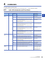
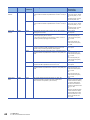
4.1
List of Commands and Functions . . . . . . . . . . . . . . . . . . . . . . . . . . . . . . . . . . . . . . . . . . . . . . . . . . . . . . . . . . 39
4.2
Device Access . . . . . . . . . . . . . . . . . . . . . . . . . . . . . . . . . . . . . . . . . . . . . . . . . . . . . . . . . . . . . . . . . . . . . . . . . . 43
Commands . . . . . . . . . . . . . . . . . . . . . . . . . . . . . . . . . . . . . . . . . . . . . . . . . . . . . . . . . . . . . . . . . . . . . . . . . . . . . 43
Device range . . . . . . . . . . . . . . . . . . . . . . . . . . . . . . . . . . . . . . . . . . . . . . . . . . . . . . . . . . . . . . . . . . . . . . . . . . . . 44
Device Read (Batch) . . . . . . . . . . . . . . . . . . . . . . . . . . . . . . . . . . . . . . . . . . . . . . . . . . . . . . . . . . . . . . . . . . . . . . 46
Device Write (Batch) . . . . . . . . . . . . . . . . . . . . . . . . . . . . . . . . . . . . . . . . . . . . . . . . . . . . . . . . . . . . . . . . . . . . . . 50
Device Read Random . . . . . . . . . . . . . . . . . . . . . . . . . . . . . . . . . . . . . . . . . . . . . . . . . . . . . . . . . . . . . . . . . . . . . 53
Device Write Random . . . . . . . . . . . . . . . . . . . . . . . . . . . . . . . . . . . . . . . . . . . . . . . . . . . . . . . . . . . . . . . . . . . . . 58
Device Read Block . . . . . . . . . . . . . . . . . . . . . . . . . . . . . . . . . . . . . . . . . . . . . . . . . . . . . . . . . . . . . . . . . . . . . . . 65
Device Write Block . . . . . . . . . . . . . . . . . . . . . . . . . . . . . . . . . . . . . . . . . . . . . . . . . . . . . . . . . . . . . . . . . . . . . . . 72
4.3
Remote Control . . . . . . . . . . . . . . . . . . . . . . . . . . . . . . . . . . . . . . . . . . . . . . . . . . . . . . . . . . . . . . . . . . . . . . . . . 80
Before the remote operation . . . . . . . . . . . . . . . . . . . . . . . . . . . . . . . . . . . . . . . . . . . . . . . . . . . . . . . . . . . . . . . . 80
Remote RUN . . . . . . . . . . . . . . . . . . . . . . . . . . . . . . . . . . . . . . . . . . . . . . . . . . . . . . . . . . . . . . . . . . . . . . . . . . . . 80
Remote STOP . . . . . . . . . . . . . . . . . . . . . . . . . . . . . . . . . . . . . . . . . . . . . . . . . . . . . . . . . . . . . . . . . . . . . . . . . . . 82
Remote PAUSE . . . . . . . . . . . . . . . . . . . . . . . . . . . . . . . . . . . . . . . . . . . . . . . . . . . . . . . . . . . . . . . . . . . . . . . . . . 82
Remote latch clear. . . . . . . . . . . . . . . . . . . . . . . . . . . . . . . . . . . . . . . . . . . . . . . . . . . . . . . . . . . . . . . . . . . . . . . . 83
Remote RESET . . . . . . . . . . . . . . . . . . . . . . . . . . . . . . . . . . . . . . . . . . . . . . . . . . . . . . . . . . . . . . . . . . . . . . . . . . 84
Processor type read . . . . . . . . . . . . . . . . . . . . . . . . . . . . . . . . . . . . . . . . . . . . . . . . . . . . . . . . . . . . . . . . . . . . . . 85
4
4.4
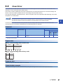
Clear Error . . . . . . . . . . . . . . . . . . . . . . . . . . . . . . . . . . . . . . . . . . . . . . . . . . . . . . . . . . . . . . . . . . . . . . . . . . . . . 87
4.5
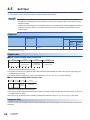
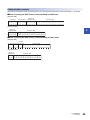
Self-Test . . . . . . . . . . . . . . . . . . . . . . . . . . . . . . . . . . . . . . . . . . . . . . . . . . . . . . . . . . . . . . . . . . . . . . . . . . . . . . . 88
4.6
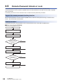
Remote Password Unlock or Lock . . . . . . . . . . . . . . . . . . . . . . . . . . . . . . . . . . . . . . . . . . . . . . . . . . . . . . . . . 90
Lock . . . . . . . . . . . . . . . . . . . . . . . . . . . . . . . . . . . . . . . . . . . . . . . . . . . . . . . . . . . . . . . . . . . . . . . . . . . . . . . . . . . 91
Unlock . . . . . . . . . . . . . . . . . . . . . . . . . . . . . . . . . . . . . . . . . . . . . . . . . . . . . . . . . . . . . . . . . . . . . . . . . . . . . . . . . 92
APPENDIX
94
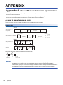
Appendix 1 Device Memory Extension Specification . . . . . . . . . . . . . . . . . . . . . . . . . . . . . . . . . . . . . . . . . . . . . . . . 94
Access to module access device. . . . . . . . . . . . . . . . . . . . . . . . . . . . . . . . . . . . . . . . . . . . . . . . . . . . . . . . . . . . . 94
Access with indirect specification of the device No. by using index register or long index register. . . . . . . . . . . 97
Access with indirect specification of the device No. by using the values stored in word device . . . . . . . . . . . . 101
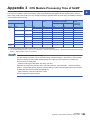
Appendix 3 CPU Module Processing Time of SLMP. . . . . . . . . . . . . . . . . . . . . . . . . . . . . . . . . . . . . . . . . . . . . . . . 105
INDEX
106
REVISIONS. . . . . . . . . . . . . . . . . . . . . . . . . . . . . . . . . . . . . . . . . . . . . . . . . . . . . . . . . . . . . . . . . . . . . . . . . . . . .108
WARRANTY . . . . . . . . . . . . . . . . . . . . . . . . . . . . . . . . . . . . . . . . . . . . . . . . . . . . . . . . . . . . . . . . . . . . . . . . . . . .109
TRADEMARKS . . . . . . . . . . . . . . . . . . . . . . . . . . . . . . . . . . . . . . . . . . . . . . . . . . . . . . . . . . . . . . . . . . . . . . . . . . 110
CONTENTS
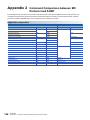
Appendix 2 Command Comparison between MC Protocol and SLMP . . . . . . . . . . . . . . . . . . . . . . . . . . . . . . . . . 104
5
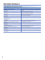
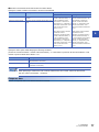
RELEVANT MANUALS
User's manuals for the applicable modules
6
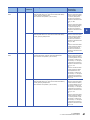
Manual name <manual number>
Description
MELSEC iQ-F FX5 User's Manual (Startup)
<JY997D58201>
Performance specifications, procedures before operation, and troubleshooting of the
CPU module.
MELSEC iQ-F FX5U User's Manual (Hardware)
<JY997D55301>
Describes the details of hardware of the FX5U CPU module, including input/output
specifications, wiring, installation, and maintenance.
MELSEC iQ-F FX5UC User's Manual (Hardware)
<JY997D61401>
Describes the details of hardware of the FX5UC CPU module, including input/output
specifications, wiring, installation, and maintenance.
MELSEC iQ-F FX5 User's Manual (Application)
<JY997D55401>
Describes basic knowledge required for program design, functions of the CPU
module, devices/labels, and parameters.
MELSEC iQ-F FX5 Programming Manual (Program Design)
<JY997D55701>
Describes specifications of ladders, ST, FBD/LD, and other programs and labels.
MELSEC iQ-F FX5 Programming Manual (Instructions, Standard
Functions/Function Blocks)
<JY997D55801>
Describes specifications of instructions and functions that can be used in programs.
MELSEC iQ-F FX5 User's Manual (Serial Communication)
<JY997D55901>
Describes N:N network, MELSEC Communication protocol, inverter communication,
non-protocol communication, and predefined protocol support.
MELSEC iQ-F FX5 User's Manual (MODBUS Communication)
<JY997D56101>
Describes MODBUS serial communication.
MELSEC iQ-F FX5 User's Manual (Ethernet Communication)
<JY997D56201>
Describes the functions of the built-in Ethernet port communication function.
MELSEC iQ-F FX5 User's Manual (SLMP)
<JY997D56001> (This manual)
Explains methods for the device that is communicating with the CPU module by
SLMP to read and write the data of the CPU module.
MELSEC iQ-F FX5 User's Manual (Positioning Control)
<JY997D56301>
Describes the built-in positioning function.
MELSEC iQ-F FX5 User's Manual (Analog Control)
<JY997D60501>
Describes the analog function.
GX Works3 Operating Manual
<SH-081215ENG>
System configuration, parameter settings, and online operations of GX Works3.
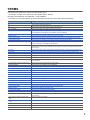
TERMS
Unless otherwise specified, this manual uses the following terms.
• indicates a variable part to collectively call multiple models or versions.
(Example) FX5U-32MR/ES, FX5U-32MT/ES FX5U-32M/ES
• For details on the FX3 devices that can be connected with the FX5, refer to FX5 User’s Manual (Hardware).
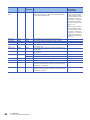
Terms
Description
■Devices
FX5
Generic term for FX5U and FX5UC PLCs
FX3
Generic term for FX3S, FX3G, FX3GC, FX3U, and FX3UC PLCs
FX5 CPU module
Generic term for FX5U CPU module and FX5UC CPU module
FX5U CPU module
Generic term for FX5U-32MR/ES, FX5U-32MT/ES, FX5U-32MT/ESS, FX5U-64MR/ES, FX5U-64MT/ES,
FX5U-64MT/ESS, FX5U-80MR/ES, FX5U-80MT/ES, and FX5U-80MT/ESS
FX5UC CPU module
Generic term for FX5UC-32MT/D and FX5UC-32MT/DSS
Extension module
Generic term for FX5 extension modules and FX3 function modules
• FX5 extension module
Generic term for I/O modules, FX5 extension power supply module, and FX5 intelligent function module
• FX3 extension module
Generic term for FX3 extension power supply module and FX3 special function blocks
Extension module (extension cable type)
Input modules (extension cable type), Output modules (extension cable type), Bus conversion module
(extension cable type), and Intelligent function modules
Extension module (extension connector type)
Input modules (extension connector type), Output modules (extension connector type), Input/output
modules, Bus conversion module (extension connector type), and Connector conversion module (extension
connector type)
I/O module
Generic term for input modules, output modules, Input/output modules, and powered input/output modules
Input module
Generic term for Input modules (extension cable type) and Input modules (extension connector type)
• Input module (extension cable type)
Generic term for FX5-8EX/ES and FX5-16EX/ES
• Input module (extension connector type)
Generic term for FX5-C32EX/D and FX5-C32EX/DS
Output module
• Output module (extension cable type)
• Output module (extension connector type)
Generic term for output modules (extension cable type) and output modules (extension connector type)
Generic term for FX5-8EYR/ES, FX5-8EYT/ES, FX5-8EYT/ESS, FX5-16EYR/ES, FX5-16EYT/ES, and
FX5-16EYT/ESS
Generic term for FX5-C32EYT/D and FX5-C32EYT/DSS
Input/output modules
Generic term for FX5-C32ET/D and FX5-C32ET/DSS
Powered input/output module
Generic term for FX5-32ER/ES, FX5-32ET/ES, and FX5-32ET/ESS
Extension power supply module
Generic term for FX5 extension power supply module and FX3 extension power supply module
• FX5 extension power supply module
Different name for FX5-1PSU-5V
• FX3 extension power supply module
Different name for FX3U-1PSU-5V
Intelligent module
The abbreviation for intelligent function modules
Intelligent function module
Generic term for FX5 intelligent function modules and FX3 intelligent function modules
• FX5 intelligent function module
Generic term for FX5 intelligent function modules
• FX3 intelligent function module
Generic term for FX3 special function blocks
Simple motion module
Expansion board
• Communication board
Expansion adapter
Different name for FX5-40SSC-S
Generic term for board for FX5U CPU module
Generic term for FX5-232-BD, FX5-485-BD, and FX5-422-BD-GOT
Generic term for adapter for FX5 CPU module
• Communication adapter
Generic term for FX5-232ADP and FX5-485ADP
• Analog adapter
Generic term for FX5-4AD-ADP and FX5-4DA-ADP
Bus conversion module
Generic term for Bus conversion module (extension cable type) and Bus conversion module (extension
connector type)
• Bus conversion module (extension cable
type)
Different name for FX5-CNV-BUS
• Bus conversion module (extension connector
type)
Different name for FX5-CNV-BUSC
Battery
Different name for FX3U-32BL
Peripheral device
Generic term for engineering tools and GOTs
GOT
Generic term for Mitsubishi Graphic Operation Terminal GOT1000 and GOT2000 series
7
Terms
Description
■Software packages
Engineering tool
The product name of the software package for the MELSEC programmable controllers
GX Works3
The product name of the software package, SWnDND-GXW3, for the MELSEC programmable controllers
(The 'n' represents a version.)
■Manuals
User's manual
Generic term for separate manuals
• User's manual (Startup)
Abbreviation of MELSEC iQ-F FX5 User's Manual (Startup)
• FX5 User's manual (Hardware)
Generic term for MELSEC iQ-F FX5U User's Manual (Hardware) and MELSEC iQ-F FX5UC User's Manual
(Hardware)
• FX5U User's manual (Hardware)
Abbreviation of MELSEC iQ-F FX5U User's Manual (Hardware)
• FX5UC User's manual (Hardware)
Abbreviation of MELSEC iQ-F FX5UC User's Manual (Hardware)
• User's manual (Application)
Abbreviation of MELSEC iQ-F FX5 User's Manual (Application)
Programming manual (Program Design)
Abbreviation of MELSEC iQ-F FX5 Programming Manual (Program Design)
Programming manual (Instructions, Standard
Functions/Function Blocks)
Abbreviation of MELSEC iQ-F FX5 Programming Manual (Instructions, Standard Functions/Function Blocks)
Communication manual
Generic term for MELSEC iQ-F FX5 User's Manual (Serial Communication), MELSEC iQ-F FX5 User's
Manual (MODBUS Communication), MELSEC iQ-F FX5 User's Manual (Ethernet Communication), and
MELSEC iQ-F FX5 User's Manual (SLMP)
• Serial communication manual
Abbreviation of MELSEC iQ-F FX5 User's Manual (Serial Communication)
• MODBUS communication manual
Abbreviation of MELSEC iQ-F FX5 User's Manual (MODBUS Communication)
• Ethernet communication manual
Abbreviation of MELSEC iQ-F FX5 User's Manual (Ethernet Communication)
• SLMP manual
Abbreviation of MELSEC iQ-F FX5 User's Manual (SLMP)
Positioning manual
Abbreviation of MELSEC iQ-F FX5 User's Manual (Positioning Control)
Analog manual
Abbreviation of MELSEC iQ-F FX5 User's Manual (Analog Control)
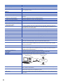
■Communication-related
Built-in RS-485 port
Built-in RS-485 port of the CPU module.
Serial port
Generic term for the four ports consisting of the FX5 Series built-in RS-485 port (CH1), communication
board (CH2), communication adapter 1 (CH3), and communication adapter 2 (CH4).
SLMP
The abbreviation for Seamless Message Protocol.
A protocol for accessing SLMP-compatible devices and PLCs that are connected to SLMP-compatible
devices from external devices.
SLMP-compatible device
Generic term for devices that can receive SLMP messages.
MC protocol
The abbreviation of the MELSEC communication protocol.
A protocol for accessing MC protocol-compatible devices and PLCs that are connected to MC protocolcompatible devices from external devices.
MC protocol-compatible device
Generic term for devices that can receive MC protocol messages.
External device
Generic term for devices of communication target (such as personal computer, HMI)
Own station
Own station indicates the station directly connected to external device.
Other station indicates a station connected to the own station on the network.
Other station
Other station
External device
Own station
Networks
Other station
8
Relay station
A station that includes two or more network modules. Transient transmission is performed through this
station to stations on other networks.
Module access device
A generic term for the module access device of the MELSEC iQ-R series/MELSEC iQ-F series and
intelligent function module device of the MELSEC-Q/L series
Buffer memory
Memory areas of Intelligent function modules and SLMP-compatible devices for storing setting values and
monitor values.
1
OUTLINE
1
This manual describes the method for reading or writing data in a CPU module with the data communication function of the
external equipment using SLMP.
When transferring data using SLMP, always refer to Page 11 SLMP DATA COMMUNICATION.
1.1
Outline of SLMP
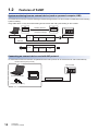
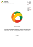
SLMP is a protocol used for access from a CPU module or an external device (such as a personal computer or an HMI) to an
SLMP compatible device through Ethernet.
SLMP communications are available among devices that can transfer messages by SLMP.
The message format of 3E frame of SLMP is the same as that of the QnA compatible 3E frame of MC
protocol.
Therefore, external devices used with MC protocol can be connected to an SLMP compatible device directly.
For details on MC protocol, refer to the following manual.
• MELSEC-Q/L MELSEC Communication Protocol Reference Manual
Device data in a CPU module can be written or read from a personal computer or an HMI by using SLMP.
Writing and reading the device allows operation monitoring, data analyzing, and production managing of a CPU module by a
personal computer or an HMI.
In addition, external illegal access can be prevented by the remote password function.
CPU module
Hub
HMI
SLMP communication
The following shows the flow for starting SLMP communication.
1.
Connect cables and external devices.
Configure the connection for the SLMP communication.
2.
Set parameters.
Set parameters with engineering tool.
3.
Write the set parameters to the CPU module.
Write set parameters to a CPU module. Validate the parameters by turning off to on or resetting the system.
1 OUTLINE
1.1 Outline of SLMP
9
1.2
Features of SLMP
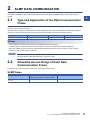
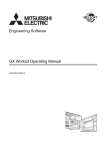
System monitoring from an external device (such as personal computer, HMI)
An external device can send a request message in SLMP message format to an CPU module to enable device read, allowing
system monitoring.
Using SLMP allows not only device data reading but also device data writing and resetting an CPU module.
100
105
100
105
Reading devices
Request message
Message format of SLMP
External device
Header
Subheader Destination
CPU module
Command
Ethernet
Message format of SLMP
Header
Subheader Destination
Data
Response message
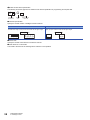
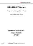
Connecting an external device used with MC protocol
An external device that uses the QnA compatible 3E frame of MC protocol can be connected to an CPU module directly.
External device (MC protocol)
CPU module
Personal computer
HMI
(Cognex product etc.)
10
1 OUTLINE
1.2 Features of SLMP
QnA compatible 3E frame
2
SLMP DATA COMMUNICATION
This chapter describes the SLMP data communication by which the external equipment reads or writes data to a CPU
module.
2.1
2
Type and Application of the Data Communication
Frame
This section describes the type and application of the frame (data communication message) by which the external equipment
accesses a CPU module with SLMP.
When the external equipment accesses a CPU module using Ethernet, the data communication is executed by sending or
receiving a command message (access request) and response message (response) of the following frame.
Target communication method
Applicable communication frames
Communication data code
Section of control procedure
Ethernet
3E frame
binary code
Page 15 MESSAGE FORMAT
3E frame
• The message format is the same as the QnA compatible 3E frame of MC protocol.
• The main purpose of the frame is to access all the devices of the CPU module from the external equipment.
• The frame enables access to the device of the MELSEC iQ-R/L/Q/A Series PLC CPUs via the CC-Link IE controller
network, CC-Link IE field network, or Ethernet.
When using binary codes, the communication time will decrease since the amount of communication data is
reduced by approximately half comparing to using ASCII codes.
2.2
Allowable Access Range of Each Data
Communication Frame
The following shows the frame and access range of a message used in SLMP.
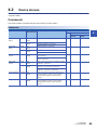
SLMP frame
Frame
Type of the network which connects the
external device with the connecting stations
Reference
Ethernet communication frame
(3E frame)
Ethernet
Page 15 MESSAGE FORMAT
2 SLMP DATA COMMUNICATION
2.1 Type and Application of the Data Communication Frame
11
Access range
Ethernet communication frame
■When the external device is connected directly with the CPU module via Ethernet
In the following system configuration, communication with the CPU module is possible using the Ethernet communication
frame from the external device.
Connecting station
A
External device
A
Ethernet
A
Assigned symbol
Description
A
Station directly connected to the external device
2.3
Concept of Control Procedure of SLMP
This section describes the concept of the procedure (control procedure) when the external equipment accesses a CPU
module with SLMP.
Sending a command message
Data communication using SLMP communication is executed in half-duplex communication.
To access the CPU module, send the next command message after receiving a response message for the preceding
command message from the CPU module.
(Until the receiving of the response message is completed, the next command message cannot be sent.)
External equipment
(Command
message)
(Command
message)
PLC CPU
(Response
message)
(Response
message)
When a response message of completion for a command message cannot be received
■When a response message of completion with an error is received
Take corrective actions depending on the error code in the response message.
■When a response message or all messages cannot be received
Resend a command message after the monitoring time of the response monitoring timer elapses.
Change the set value of the monitoring time as needed.
12
2 SLMP DATA COMMUNICATION
2.3 Concept of Control Procedure of SLMP
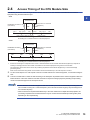
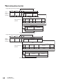
2.4
Access Timing of the CPU Module Side
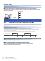
The following shows the access timing of the CPU module side when the CPU module is accessed from the external
equipment using the built-in Ethernet port.
• RUN
2
External device
Response to a command
(Response)
Read/Write command
(Command)
1)
2) ACK*1
ACK*1
CPU module
Step 0
END Step 0
Step 0
END
END processing END processing
END Step 0
END
END processing
Processing for a command from the external equipment
• STOP
External device
Response to a command
(Response)
Read/Write command
(Command)
1)
ACK*1
2) ACK*1
CPU module
END
END
END processing
END
END processing
END
END
END processing END processing
Processing for a command from the external equipment
*1
1.
ACK shown in the figure is a response which is sent or received between the CPU module and external equipment (a response for
receiving a massage) when the CPU module is accessed from the external equipment using TCP/IP communication.
This response is not the same as the one for the processing requested from the external equipment by a command message
(processing result).
When access is executed using UDP/IP communication via the built-in Ethernet port, an ACK response is not sent.
To send a read request or a write request to the CPU module side from the external equipment, a command message is
sent.
2.
The CPU module reads or writes the data according to the description requested from the external equipment when the
END instruction of the CPU module is executed and sends a response message (response) including the processing
result to the external equipment of the request source.
• Access between the external equipment and CPU module is processed at each END processing when the
CPU module is running for a command request. (The scan time becomes longer by the processing time of
the command request.)
• When accesses are requested simultaneously to the CPU module from multiple external equipment, the
processing requested from the external device may be on hold until several END processings take place
depending on the request timing.
2 SLMP DATA COMMUNICATION
2.4 Access Timing of the CPU Module Side
13
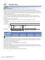
2.5
Transfer Time
Link time
■Calculation method
Calculate the minimum processing time of the SLMP communication by the following calculation formula.
However, the processing time may become longer depending on the load of the network (how much a line is crowded),
window size of each connecting device, number of connections to be used simultaneously, and system configuration. As a
guideline, recognize the value calculated by the following calculation formula as the processing time when a communication is
executed by only one connection.
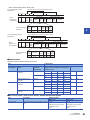
• Minimum processing time of the SLMP communication (for batch read or batch write)
Tfs = Ke + (Kdt Df) + Scr Number of scans required for processing + ACK processing time of external equipment
Tfs: Time from when the request data of a personal computer is received until the CPU module completes the processing
(Unit: ms) *1
Ke, Kdt: Constant (Refer to the following table.)
Df: Number of words of the request data + Number of words of the response data (application data part)
Scr: Scan time
*1
The following shows the timing from when the request data of a personal computer is received until the CPU module completes the
processing.
External device
(personal computer)
Command
message
Response
message
ACK (only
for TCP)
END
Step 0
ACK (only
for TCP)
Step 0
END
Scan time of the
CPU module
Tfs
Communication
description
TCP/IP communication
UDP/IP communication
Ke
Kdt
Ke
Kdt
Batch read
1
0.001
1
0.001
Batch write
1
0.001
1
0.001
Ex.
[Calculation example 1]
Time from when the request data of a personal computer is received until the processing is completed, when a TCP/IP
communication is executed between personal computers and 32 points data read from the data register (D) of own station by
the SLMP communication in binary code (Unit: ms)
The scan time of the mounted station is 40 ms.
Tfs = 1 + (0.001 32)+40 1 + ACK processing time of external equipment
[Calculation example 2]
Time from when the request data of a personal computer is received until the processing is completed, when a TCP/IP
communication is executed between personal computers and 32 points data written to the data register (D) of own station by
the SLMP communication in binary code (Unit: ms)
The scan time of the mounted station is 40 ms.
Tfs = 1 + (0.001 32)+40 1 + ACK processing time of external equipment
14
2 SLMP DATA COMMUNICATION
2.5 Transfer Time
3
MESSAGE FORMAT
This chapter describes the message data format, the data specification method, and limitations etc. when performing SLMP
data communication using the 3E frame to the built-in Ethernet port.
Frame type
Built-in Ethernet port
Remark
3E frame
Communicable
The message format is the same as the QnA compatible 3E frame
3.1
3
Message Format
This section describes the message format for each command when performing the data communication using the 3E frame.
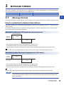
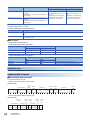
How to understand command descriptions
This section describes how to understand message diagrams in each command description shown in Page 43 Device
Access and after.
The following example shows how to understand message diagrams in command descriptions for each control procedure
when communicating with the built-in Ethernet port.
When data is read from a CPU module by external equipment
(Command message)
External
equipment
E
N
Q
Part A
S
T
X
CPU module
Part B
(Response message)
• Part A indicates transfer from the external equipment to the CPU module.
• Part B indicates transfer from the CPU module to the external equipment.
• Create a program in the external equipment so that each data is transferred sequentially from the left to the right.
Ex.
In part A, data is sent sequentially starting from ENQ. In part B, data is received sequentially starting from STX.
When data is written from external equipment to a CPU module
External
equipment
E
N
Q
Part C
A
C
K
CPU module
Part B
(Response message)
• Part C indicates transfer from the external equipment to the CPU module.
• Part B indicates transfer from the CPU module to the external equipment.
• Create a program in the external equipment so that each data is transferred sequentially from the left to the right.
Ex.
In part C, data is sent sequentially starting from ENQ. In part B, data is received sequentially starting from ACK.
After receiving a command message from the external equipment, the CPU module completes the processing
for part A and part C in the message and sends a response message part B, then starts the receiving wait
status (neutral status).
3 MESSAGE FORMAT
3.1 Message Format
15
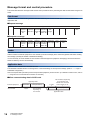
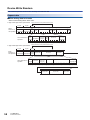
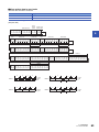
Message format and control procedure
This section describes the message format and the control procedures when performing the data communication using the 3E
frame.
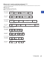
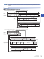
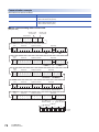
Data format
The data format for communicating between the built-in Ethernet port and the external device consists of header and
application data.
■Request message
Header
Application data
Subheader
Request Request Reserve Command Subcommand Request
Request
Request
Request
data
destination destination destination destination data
network station No. module I/O multidrop length
station No.
No.
No.
■Response message
Header
Application data
Subheader
Request Response
Request
Request
Request
destination destination destination destination data length
network station No. module I/O multidrop
station No.
No.
No.
End
code
Response
data
Header
This header is for TCP/IP and UDP/IP.
Add the header for external equipment to CPU module (command message) at the external equipment side before sending
the message (normally the header is added automatically).
It is not necessary to set the header for CPU module to external equipment (response message) by the user because the
header is added by the CPU automatically.
Application data
Application data is divided into subheader and text.
The subheader indicates whether a message is the command message or the response message. (Refer to Page 17
Subheader configuration.)
Text is the request data (command) and the response date (response) in each function. (For details on each function, refer to
Page 39 List of Commands and Functions or and after.)
■When communicating data in ASCII code
4 bytes
The text differs depending
on the function and
whether the command
ends normally or not.
Subheader
Text (response)
Application data
External equipment
CPU module
16
3 MESSAGE FORMAT
3.1 Message Format
Subheader
Text (command)
4 bytes
The text differs
depending on
the function.
Application data
■When communicating data in binary code
2 bytes
The text differs depending
on the function and
whether the command
ends normally or not.
Subheader
Text (response)
Application data
External equipment
Subheader
Text (command)
2 bytes
The text differs
depending on
the function.
CPU module
Application data
3
It is not necessary to set the response to a command from the external equipment by the user because the
response is created and sent by the CPU module.
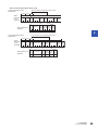
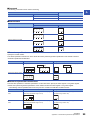
Subheader configuration
This section describes the subheader configuration.
■When communicating data in ASCII code
Command message
5
0
0
0
35H 30H 30H 30H
Response message
D
0
0
0
44H 30H 30H 30H
■When communicating data in binary code
Command message
Response message
50H 00H
D0H 00H
Control procedure
This section describes the control procedures and the format of the application data when performing the data
communication.
The (Thick line) part shown in the message explanation diagram of this section are items common to all commands and
correspond to the * portion of the message explanation diagrams indicated in Page 72 Device Write Block or after in this
chapter.
For the data contents and the data specification method of the (Thick line) part, refer to Page 22 Application data
specification items.
Data code (ASCII/binary) to be used when communicating, it is determined by the parameters of the GX
Works3.
[Module Parameter] [Ethernet Port] [Communication Data Code]
3 MESSAGE FORMAT
3.1 Message Format
17
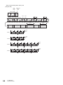
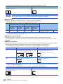
■When communicating data in ASCII code
• When data is read from a CPU module by external equipment
External equipment
CPU module (command message)
Character area A
Text (command)
H L H L H - - L H L H - - L H - - L H
5 0 0 0 0 0 F F 0 3 F F 0 0 0 0 1 8 0 0 1 0
35H 30H 30H 30H 30H 30H 46H 46H 30H 33H 46H 46H 30H 30H 30H 30H 31H 38H 30H 30H 31H 30H
(Example)
-
Subcommand
Command
Reserved
Request data length
Request destination
multi-drop station
number
Request destination
module I/O number
Request destination
station number
Network number
Subheader
Header
(Data name)
Request data area
-
L H
-
-
L
((Example) For 24 bytes)
CPU module
The order of data items differs depending on
the command or subcommand. For details,
refer to the description on command details
in Section 4.2 or later.
External equipment (response message)
(When completed normally)
Character area B
Text (response)
End code
Response data length
Request destination
multi-drop station
number
Request destination
module I/O number
Request destination
station number
Network number
Subheader
Header
Response data area
H L H L H - - L H L H - - L H - - L
D 0 0 0 0 0 F F 0 3 F F 0 0 0 0 0 C 0 0 0 0
44H 30H 30H 30H 30H 30H 46H 46H 30H 33H 46H 46H 30H 30H 30H 30H 30H 43H 30H 30H 30H 30H
((Example) For 12 bytes)
(When completed with error)
Text (response)
(22 bytes)
18
3 MESSAGE FORMAT
3.1 Message Format
-
Subcommand
(For C051H)
H L H L H - - L H L H - - L H - - L H L H L H - - L H L H
D 0 0 0 0 0 F F 0 3 F F 0 0 0 0 1 6 C 0 5 1 0 0 F F 0 3 F F 0 0
44H 30H 30H 30H 30H 30H 46H 46H 30H 33H 46H 46H 30H 30H 30H 30H 31H 36H 43H 30H 35H31H 30H 30H 46H 46H 30H 33H 46H 46H 30H 30H
Command
Request destination
multi-drop station
number
Request destination
module I/O number
Request destination
station number
(responding station)
Network number
(responding station)
End code
other than 0H
Response data length
Request destination
multi-drop station
number
Request destination
module I/O number
Request destination
station number
(access station)
Network number
(access station)
Subheader
Header
Error information area
-
L H
-
-
L
• When data is written from external equipment to a CPU module
External equipment
CPU module (command message)
Character area C
Text (command)
H L H L H - - L H L H - - L H - - L H
5 0 0 0 0 0 F F 0 3 F F 0 0 0 0 2 0 0 0 1 0
35H 30H 30H 30H 30H 30H 46H 46H 30H 33H 46H 46H 30H 30H 30H 30H 32H 30H 30H 30H 31H 30H
(Example)
-
Subcommand
Command
Reserved
Request data length
Request destination
multi-drop station
number
Request destination
module I/O number
Request destination
station number
Network number
Subheader
Header
(Data name)
Request data area
-
L H
-
-
3
L
((Example) For 32 bytes)
CPU module
The order of data items differs depending on
the command or subcommand. For details,
refer to the description on command details
in Section 4.2 or later.
External equipment (response message)
(When completed normally)
Text (response)
End code
Response data length
Request destination
multi-drop station
number
Request destination
module I/O number
Request destination
station number
Network number
Subheader
Header
H L H L H - - L H L H - - L H - - L
D 0 0 0 0 0 F F 0 3 F F 0 0 0 0 0 4 0 0 0 0
44H 30H 30H 30H 30H 30H 46H 46H 30H 33H 46H 46H 30H 30H 30H 30H 30H 34H 30H 30H 30H 30H
(4 bytes)
(When completed with error)
Text (response)
-
Subcommand
(For C051H)
H L H L H - - L H L H - - L H - - L H L H L H - - L H L H
D 0 0 0 0 0 F F 0 3 F F 0 0 0 0 1 6 C 0 5 1 0 0 F F 0 3 F F 0 0
44H 30H 30H 30H 30H 30H 46H 46H 30H 33H 46H 46H 30H 30H 30H 30H 31H 36H 43H 30H 35H31H 30H 30H 46H 46H 30H 33H 46H 46H 30H 30H
Command
Request destination
multi-drop station
number
Request destination
module I/O number
Request destination
station number
(responding station)
Network number
(responding station)
End code
other than 0H
Response data length
Request destination
multi-drop station
number
Request destination
module I/O number
Request destination
station number
(access station)
Network number
(access station)
Subheader
Header
Error information area
-
L H
-
-
L
(22 bytes)
3 MESSAGE FORMAT
3.1 Message Format
19
■When communicating data in binary code
• When data is read from a CPU module by external equipment
External equipment
CPU module (command message)
Character area A
Text (command)
Request data area
Subcommand
L
H L
H
L
H
50H 00H 00H FFH FFH 03H 00H 0CH 00H 10H 00H
(Example)
Command
Reserved
Request data length
Request destination
multi-drop station number
Request destination
module I/O number
Request destination
station number
Network number
Subheader
Header
(Data name)
L
H
L
H
((Example) For 12 bytes)
CPU module
External equipment (response message)
(When completed normally)
The order of data items differs depending on
the command or subcommand. For details,
refer to the description on command details
in Section 4.2 or later.
Character area B
Text (response)
Response data area
End code
Response data length
Request destination
multi-drop station number
Request destination
module I/O number
Request destination
station number
Network number
Subheader
Header
L
H L
H
L
H
D0H 00H 00H FFH FFH 03H 00H 06H 00H 00H 00H
((Example) For 6 bytes)
(When completed with error)
Text (response)
Error information area
(11 bytes)
20
3 MESSAGE FORMAT
3.1 Message Format
L
Subcommand
L
H L
H
L
H
L
H
D0H 00H 00H FFH FFH 03H 00H 0BH 00H 51H C0H 00H FFH FFH 03H 00H
Command
Request destination
multi-drop station number
Request destination
module I/O number
Request destination station
number (responding station)
Network number
(responding station)
End code
other than 0H
Response data length
Request destination
multi-drop station number
Request destination
module I/O number
Request destination station
number (access station)
Network number
(access station)
Subheader
Header
(For C051H)
H
L
H
• When data is written from external equipment to a CPU module
End code
Response data length
Request destination
multi-drop station number
Request destination
module I/O number
Request destination
station number
Network number
Subheader
Header
Character area A
Text (command)
Subcommand
Command
Request destination
multi-drop station number
Request destination
module I/O number
H
L
H
L
L
H L
H
L
H
L
H
D0H 00H 00H FFH FFH 03H 00H 0BH 00H 51H C0H 00H FFH FFH 03H 00H
Request destination station
number (responding station)
Network number
(responding station)
End code
other than 0H
Header
Subheader
Request destination station
number (access station)
Network number
(access station)
Request destination
module I/O number
Request destination
multi-drop station number
Response data length
(For C051H)
Subcommand
(When completed normally)
Command
Reserved
Request destination
station number
Request destination
module I/O number
Request destination
multi-drop station number
Request data length
3
Network number
External equipment (response message)
The order of data items differs depending on
the command or subcommand. For details,
refer to the description on command details
in Section 4.2 or later.
CPU module
H
L
H
L
L
H L
H
L
H
50H 00H 00H FFH FFH 03H 00H 0CH 00H 10H 00H
(Example)
Subheader
Header
(Data name)
CPU module (command message)
External equipment
Request data area
((Example) For 12 bytes)
Text (response)
L
H L
H
L
H
D0H 00H 00H FFH FFH 03H 00H 02H 00H 00H 00H
(2 bytes)
(When completed with error)
Text (response)
Error information area
(11 bytes)
21
3 MESSAGE FORMAT
3.1 Message Format
Application data specification items
This section describes the data contents and the specification method of common data items in the application data in each
message when performing the data communication using the 3E frame.
Request destination network number and request destination station number
■Request message
Header
Application data
Subheader
Request Request Reserve Command Subcommand Request
Request
Request
Request
data
destination destination destination destination data
network station No. module I/O multidrop length
station No.
No.
No.
■Response message
Header
Application data
Subheader
Request Response
Request
Request
Request
destination destination destination destination data length
network station No. module I/O multidrop
station No.
No.
No.
End
code
Response
data
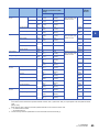
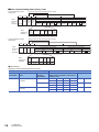
Specify the request destination network number and request destination station number to be used as an access destination
in hexadecimal.
Specify the request destination network number and request destination station number according to installation conditions of
access destination stations based on the following table.
Data of the response message is a value set in the request message.
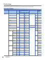
No.
Access destination
Station to be specified
Request destination
network number
Request destination station
number
1*1
Connecting station
(Within the range indicated in No.
1 in the figure below)
(Specify the fixed value indicated
on the right)
00H
FFH
2
Other stations or relay station
(Within the range indicated in No.
2 in the figure below)
Access destination station
01 to EFH (1 to 239)
01 to 78H (1 to 120): Station
number
7DH: Assigned control station/
Master station
7EH: Present control station/
Master station
3
Multi-drop connecting station via
network
(Within the range indicated in No.
3 in the figure below)
A station on the network where
multi-drop connecting stations are
connected
(In the figure below, [A] is
specified)
01 to EFH (1 to 239)
01 to 78H (1 to 120): Station
number
7DH: Assigned control station/
Master station
7EH: Present control station/
Master station
*1
Please use specification No.1 to access FX5CPU.
Another station
Another station
Multi-drop connection
Connecting
station
External device
Relay
station
Network
No. n
Network
No. 1
Another station
22
3 MESSAGE FORMAT
3.1 Message Format
Multi-drop
connecting
station
A
MELSEC iQ-R
series etc.
Ethernet
No. 1
Multi-drop
connecting
station
Another station
No. 2
No. 3
Multi-drop
connecting
station
Ex.
When specifying 26 (1AH) as the station number n and 16 (10H) as the station number of station A
ASCII code
1
A
1
0
31H 41H 31H 30H
Network number Station number
Binary code
1AH 10H
Network number Station number
Precautions
3
The stations of network number 240 to 255 cannot be accessed.
FX5CPU cannot perform multi-drop connection.
FX5CPU cannot perform connection via network.
Request destination module I/O number
■Request message
Header
Application data
Subheader
Request Request Reserve Command Subcommand Request
Request
Request
Request
data
destination destination destination destination data
network station No. module I/O multidrop length
station No.
No.
No.
■Response message
Header
Application data
Subheader
Request Response
Request
Request
Request
destination destination destination destination data length
network station No. module I/O multidrop
station No.
No.
No.
End
code
Response
data
Select the module number of the access destination from the table below.
When the send destination of the request message is a multi-drop connecting station that is connected to the request
destination station, set the I/O number (upper 3-digits) of the serial communication module which is performing the multi-drop
connection.
Module to be accessed*1
Request destination station
Request destination module I/O number
1*2
Own station
03FFH
2
Other station (control CPU)
03FFH
3
The module which is performing multi-drop connection with serial
communication module ("A" in the figure below), which is connected to the
network
0000H to 01FFH
No.
*1
*2
FX5CPU cannot perform multi-drop connection.
FX5CPU cannot perform connection via network.
Please use specification No.1 to access FX5CPU.
Another station
Another station
Multi-drop connection
Multi-drop
connecting
station
Relay
station
Connecting
station
External device
Network
No. n
Network
No. 1
Multi-drop
connecting
station
A
MELSEC iQ-R
series etc.
Ethernet
Another station
No. 1
Multi-drop
connecting
station
Another station
No. 2
No. 3
3 MESSAGE FORMAT
3.1 Message Format
23
Ex.
When specifying the default processor (0005H) as the request destination module I/O number
ASCII code
Binary code
0
0
0
5
30H 30H 30H 35H
05H 00H
Request destination
module I/O No.
Request destination
module I/O No.
Request destination multi-drop station number
■Request message
Header
Application data
Subheader
Request Request Reserve Command Subcommand Request
Request
Request
Request
data
destination destination destination destination data
network station No. module I/O multidrop length
station No.
No.
No.
■Response message
Header
Application data
Subheader
Request Response
Request
Request
Request
destination destination destination destination data length
network station No. module I/O multidrop
station No.
No.
No.
End
code
Response
data
Specify the station number of the SLMP compatible device linked by the multi-drop connection in the access destination,
within the range shown in the table below.
When not specifying the SLMP compatible device linked by the multi-drop connection, set 00H.
No.
Access station of external equipment
Request destination multi-drop station number
1
Stations on the multi-drop connection
("F" in the figure below)
Set the station number (00H to 1FH (0 to 31))
("F" in the figure below)
2
A station that relays the network and the multi-drop connection
("E" in the figure below)
00H (0)
3*1
Other than above
00H (0)
*1
Please use specification No.3 to access FX5CPU.
Another station
Another station
B
D
Relay
station
Connecting
station
External device
A
Network
No. 1
C
B
D
Another station
Another station
No. 3
Ex.
24
3 MESSAGE FORMAT
3.1 Message Format
Multi-drop
connecting
station
E
F
F
No. 2
When specifying 00H as the requested multi-drop station number
0
0
30H 30H
Requested multi-drop
station number
Multi-drop
connecting
station
MELSEC iQ-R
series etc.
Ethernet
ASCII code
Network
No. n
Multi-drop connection
Multi-drop
connecting
station
Binary code
00H
Requested multi-drop
station number
No. 1
Request data length
■Request message
Header
Application data
Subheader
Request Request Reserve Command Subcommand Request
Request
Request
Request
data
destination destination destination destination data
network station No. module I/O multidrop length
station No.
No.
No.
3
Specify the total data size from the reserve to the request data in hexadecimal. (Unit: byte)
Ex.
When the request data length is 24 (18H) bytes
ASCII code
0
0
1
8
30H 30H 31H 38H
Request data length
Binary code
18H 00H
Request data length
Response data length
■Response message
When normally completed, the total data size from the end code to the response data is set in hexadecimal. When completed
with error, the total data size from the end code to the error information is set in hexadecimal. (Unit: byte)
(When completed normally)
Header
Subheader
Request Request
destination destination
network station
number number
Request
destination
module I/O
number
Request
destination
multi-drop
station
number
Response
data length
Request
destination
module I/O
number
Request
destination
multi-drop
station
number
Response
data length
End code
Response data
(When completed with error)
Header
Subheader
Request Request
destination destination
network station
number number
(access (access
station) station)
End code
Request Request
destination destination
network
station
number
number
(responding (responding
station)
station)
Request
destination
module I/O
number
Request
destination
multi-drop
station
number
Command
Subcommand
Error information
3 MESSAGE FORMAT
3.1 Message Format
25
Reserved
■Request message
Header
Application data
Subheader
Request Request Reserve Command Subcommand Request
Request
Request
Request
data
destination destination destination destination data
network station No. module I/O multidrop length
station No.
No.
No.
Setting range:
• Set 0000H (0).
Ex.
ASCII code
Binary code
0
0
0
0
30H 30H 30H 30H
00H 00H
End code
■Response message
Header
Application data
Subheader
Request Response
Request
Request
Request
destination destination destination destination data length
network station No. module I/O multidrop
station No.
No.
No.
End
code
Response
data
The command processing result is stored.
When normally completed, "0" is stored. When completed with error, an error code set at the request destination is stored.
(For the set error code and corresponding error contents, refer to manuals of the SLMP compatible device of the response
station.)
Ex.
When failed
(for 0400H)
When completed
ASCII code
0
0
0
0
30H 30H 30H 30H
ASCII code
0
4 0 0
30H 34H 30H 30H
Binary code
Binary code
00H 00H
00H 04H
Request data
■Request message
Header
Application data
Subheader
Request Request Reserve Command Subcommand Request
Request
Request
Request
data
destination destination destination destination data
network station No. module I/O multidrop length
station No.
No.
No.
Set a command to be executed and data for the argument of the subcommand.
(Some commands and subcommands do not require the request data specification.)
For details of the request data, refer to Page 43 Device Access.
26
3 MESSAGE FORMAT
3.1 Message Format
Response data
■Response message
Header
Application data
Subheader
Request Response
Request
Request
Request
destination destination destination destination data length
network station No. module I/O multidrop
station No.
No.
No.
End
code
Response
data
3
The processing result of the request data is stored.
(Some commands do not return response messages.)
For details of the response data, refer to Page 43 Device Access.
Error information
The request destination network number, request destination station number, request destination module I/O number, and
request destination multi-drop station number of the station which responded with errors are stored.
Numbers which differ from the requested station specified by the request message may be stored because the information of
the station which responded with errors is stored.
The command and the subcommand specified by the request message of the request data are stored.
Transfer data in character area
This section describes how to transfer bit device data and word device data and data alignment in the character area sent and
received between the external equipment and the CPU module by using each command.
The transfer data explained below is handled as the character area B for reading and monitoring and the character area C for
writing, testing, and registering the monitor data are stored.
Character area
■Request message
Header
Application data
Subheader
Request Request Reserve Command Subcommand Request
Request
Request
Request
data
destination destination destination destination data
network station No. module I/O multidrop length
station No.
No.
No.
Character area
A and C
■Response message
Header
Application data
Subheader
Request Response
Request
Request
Request
destination destination destination destination data length
network station No. module I/O multidrop
station No.
No.
No.
End
code
Response
data
Character area B
3 MESSAGE FORMAT
3.1 Message Format
27
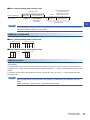
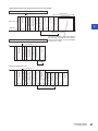
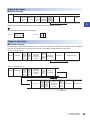
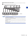
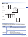
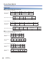
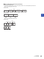
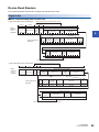
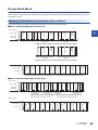
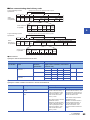
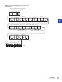
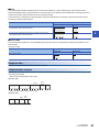
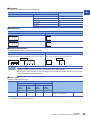
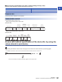
Communicating data (when communicating in ASCII code)
■When bit device memory is read or written
The bit device memory is handled in 1-bit (1-point) units or in 1-word (16-point) units.
The transfer data in each case is described below.
• In 1-bit (1-point) units
When the bit device memory is handled in 1-bit (1-point) units, a specified number of devices starting from the specified start
device are expressed in turn from the left end in "1 (31H)" for the on status or "0 (30H)" for the off status.
Ex.
When indicating the on/off status of five devices starting from M10
Device
code
M
*
Number of
adevices
Head device No.
0
0
0
0
1
0
0
0
0
Data
5
1
0
1
0
1
4DH 2AH 30H 30H 30H 30H 31H 30H 30H 30H 30H 35H 31H 30H 31H 30H 31H
Indicates that M14 is ON.
Indicates that M13 is OFF.
Indicates that M12 is ON.
Indicates that M11 is OFF.
Indicates that M10 is ON.
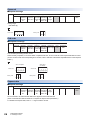
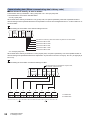
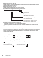
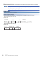
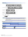
• In 1-word (16-point) units
When the bit device memory is handled in 1-word units, one word is expressed in 4-bit units in turn from the most significant
bit in hexadecimal.
Ex.
When indicating the on/off status of 32 devices starting from M16
Because devices are handled in 16 point units,
the number of device is "0002".
Devide
code
M
*
Number of
devices
Head device No.
0
0
0
0
1
6
0
0
0
Data
2
A
B
1
Data
2
3
4
C
D
4DH 2AH 30H 30H 30H 30H 31H 36H 30H 30H 30H 32H 41H 42H 31H 32H 33H 34H 43H 44H
A
B
1
2
3
4
C
D
b15 b14 b13 b12 b11 b10 b9 b8 b7 b6 b5 b4 b3 b2 b1 b0 b15 b14 b13 b12 b11 b10 b9 b8 b7 b6 b5 b4 b3 b2 b1 b0
1: Indicates ON.
1 0 1 0 1 0 1 1 0 0 0 1 0 0 1 0 0 0 1 1 0 1 0 0 1 1 0 0 1 1 0 1
M M M M M M M M M M M M M M M M M M M M M M M M M M M M M M M M
31 30 29 28 27 26 25 24 23 22 21 20 19 18 17 16 47 46 45 44 43 42 41 40 39 38 37 36 35 34 33 32
Head End
28
3 MESSAGE FORMAT
3.1 Message Format
0: Indicates OFF.
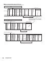
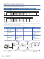
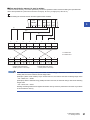
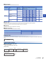
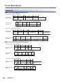
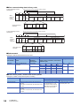
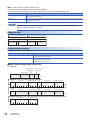
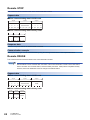
■When word device memory is read or written
In the case of word device memory, one word is expressed in 4-bit units in turn from the most significant bit in hexadecimal.
Ex.
When indicating the contents stored in the data registers D350 and D351
Device
code
Number of
devices
Head device No.
Data
Data
5
7
F
6
A B
1
0
D
*
0
0
0
3
5
0
0
0
0
2
44H 2AH 30H 30H 30H 33H 35H 30H 30H 30H 30H 32H 35H 36H 41H 42H 31H 37H 30H 46H
5
6
A
B
1
7
0
3
F
b15 b14 b13 b12 b11 b10 b9 b8 b7 b6 b5 b4 b3 b2 b1 b0 b15b14b13b12 b11 b10 b9 b8 b7 b6 b5 b4 b3 b2 b1 b0
1: Indicates ON.
0 1 0 1 0 1 1 0 1 0 1 0 1 0 1 1 0 0 0 1 0 1 1 1 0 0 0 0 1 1 1 1
Indicates that D350 stores
"56ABH ("22187" in decimal)".
0: Indicates OFF.
Indicates that D351 stores
"170FH ("5903" in decimal)".
Use capitalized code for alphabetical letter.
When data other than integer value (real number, character string), is stored in the word device memory for
reading data, the stored value are read as integer value.
(Example 1) When a real number (0.75) is stored in D0 to D1, the value is read as the following integer value.
• D0 = 0000H, D1 = 3F40H
(Example 2) When a character string (12AB) is stored in D2 to D3, the character string is read as the following
integer value.
• D2 = 3231H, D3 = 4241H
Data in word units handled when reading and writing buffer memory areas is expressed in the same way as
the word device memory.
3 MESSAGE FORMAT
3.1 Message Format
29
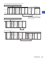
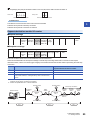
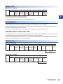
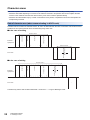
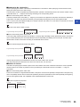
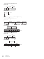
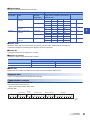
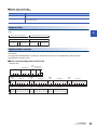
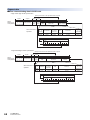
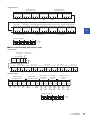
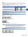
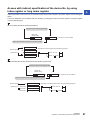
Communicating data (When communicating data in binary code)
■When bit device memory is read or written
The bit device memory is handled in 1-bit (1-point) units or in 1-word (16-point) units.
The transfer data in each case is described below.
• In 1-bit (1-point) units
When the bit device memory is handled in 1-bit (1-point) units, one point is specified by 4-bits and a specified number of
devices starting from the specified start device are expressed in turn from the most significant bit as "1" for the on status or "0"
for the off status.
Ex.
When indicating the on/off status of five devices starting from M10
Head
Device Number
Data
of
device
code
devices
number
0005H
00000AH
L H
L - H
0AH 00H 00H 90H 05H 00H 10H 10H 10H
0 is shown as a dummy when the number of points is an odd number.
Indicates that M14 is ON.
Indicates that M13 is OFF.
Indicates that M12 is ON.
Indicates that M11 is OFF.
Indicates that M10 is ON.
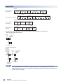
• In 1-word (16-point) units
When the bit device memory is handled in 1-word (16-point) units, one point is specified by 1-bit and a specified number of
devices starting from specified start device are expressed in 16-point units in turn from Low byte (L: bit 0 to 7) to High byte (H:
bit 8 to 15).
Ex.
When indicating the on/off status of 32 devices starting from M16
Because devices are handled in 16 point units,
the number of device is "02".
Head
device
number
000010H
L
H
10H 00H 00H
1
2
A
B
C
Device
code
90H
Number
of
devices
0002H
Data
Data
AB12H
34CDH
L
L
H
H
H
L
02H 00H 12H ABH CDH 34H
D
3
4
b7 b6 b5 b4 b3 b2 b1 b0 b15 b14 b13 b12 b11b10 b9 b8 b7 b6 b5 b4 b3 b2 b1 b0 b15 b14 b13 b12 b11b10 b9 b8
1: Indicates ON.
0 0 0 1 0 0 1 0 1 0 1 0 1 0 1 1 1 1 0 0 1 1 0 1 0 0 1 1 0 1 0 0
M M M M M M M M M M M M M M M M M M M M M M M M M M M M M M M M
23 22 21 20 19 18 17 16 31 30 29 28 27 26 25 24 39 38 37 36 35 34 33 32 47 46 45 44 43 42 41 40
Head
30
3 MESSAGE FORMAT
3.1 Message Format
End
0: Indicates OFF.
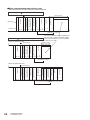
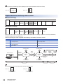
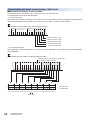
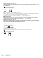
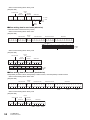
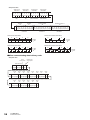
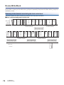
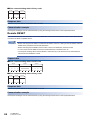
■When word device memory is read or written
In the word device memory, one word is specified by 16-bit and a specified number of devices starting from specified start
device are expressed in 1-point units in turn from Low byte (L: bit 0 to 7) to High byte (H: bit 8 to 15).
Ex.
When indicating the contents stored in the data registers D350 and D351
Head
device
number
00015EH
L
H
5EH 01H 00H
Device
code
A8H
Number
of
devices
0002H
Data
Data
56ABH
170FH
3
H
L
L
H
L
H
02H 00H ABH 56H 0FH 17H
(L)
(H)
(L)
(H)
A
B
5
6
0
F
1
7
b7 b6 b5 b4 b3 b2 b1 b0 b15 b14 b13 b12 b11b10 b9 b8 b7 b6 b5 b4 b3 b2 b1 b0 b15 b14 b13 b12 b11b10 b9 b8
1 0 1 0 1 0 1 1 0 1 0 1 0 1 1 0 0 0 0 0 1 1 1 1 0 0 0 1 0 1 1 1
1: Indicates ON.
0: Indicates OFF.
5
6
A
B
1
7
0
F
b15 b14 b13 b12 b11b10 b9 b8 b7 b6 b5 b4 b3 b2 b1 b0 b15 b14 b13 b12 b11b10 b9 b8 b7 b6 b5 b4 b3 b2 b1 b0
0 1 0 1 0 1 1 0 1 0 1 0 1 0 1 1 0 0 0 1 0 1 1 1 0 0 0 0 1 1 1 1
Indicates that D350 stores
"56ABH ("22187" in decimal)".
Indicates that D351 stores
"170FH ("5903" in decimal)".
When data other than integer value (real number, character string), is stored in the word device memory for
reading data, the stored value are read as integer value.
(Example 1) When a real number (0.75) is stored in D0 to D1, the value is read as the following integer value.
• D0 = 0000H, D1 = 3F40H
(Example 2) When a character string (12AB) is stored in D2 to D3, the character string is read as the following
integer value.
• D2 = 3231H, D3 = 4241H
Reading and writing extension file registers and buffer memory areas are performed in the same way as those
of the word device memory.
3 MESSAGE FORMAT
3.1 Message Format
31
Character areas
This section explains character areas in the control procedure (data area when communicating in binary code).
• Character areas differ depending on command to be used and contents to be specified. This section explains the data
common to the character area when the device memory to be read or written is specified directly.
• Character area data handled only by a certain command and not by others, is explained in the section that explains the
corresponding command.
Data of character area (when communicating in ASCII code)
The data order and contents of character areas A, B, and C are identical when the same command is used under the same
conditions in the control procedure when communicating using ASCII code.
■In the case of reading
Character area A
-
-
L
H
-
-
Number of devices
H
Head device
*
Device code
Subcommand
External
equipment
-
-
L
H
-
*
-
Character area B
L
*
Data on specified
number of device points
PLC CPU
*
■In the case of writing
Character area C
-
L
H
-
-
-
-
L
H
-
-
L
Data on specified
number of device points
-
Number of devices
H
Head device
*
Device code
Subcommand
External
equipment
*
PLC CPU
The data array and the data contents marked with * are shown in Page 15 Message Format.
32
3 MESSAGE FORMAT
3.1 Message Format
*
Data of data area (when communicating in binary code)
■In the case of reading
Data area (corresponding to character area A)
L
H L
-
H
Number of devices
*
Device code
Head device No.
Subcommand
External
equipment
L
H
*
Data on specified
number of device points
CPU module
3
Data area
(corresponding to
character area B)
■In the case of writing
Data area (corresponding to character area C)
L
-
H
L
H
Data on specified number
of device points
H
Number of devices
L
Device code
*
Head device No.
Subcommand
External
equipment
CPU module
*
The data array and the data contents marked with * are shown in Page 15 Message Format.
Data contents common to character areas
■Subcommand
Subcommands are data for specifying the unit for reading and writing, device type to be specified, and the data reading
condition.
The following table shows the details of setting items.
Setting item
Data size specification
Device specification
format
Device memory
extension specification
Description
Word units
• The target data is read or written in word units.
• Select "0" even when the reading data or writing data does not exist in arguments of the command.
Bit units
The target data is read or written in bit units.
2 digit code/6 digit
number
specification
Data or items related to the address specifications are expressed in the following sizes, which are the same
as the existing setting.
• Device code: 1 byte in binary
• Device number: 3 bytes in binary
4 digit code/8 digit
number
specification
Data or items related to the address specifications are extended to the following size.
• Device code: 2 byte in binary
• Device number: 4 bytes in binary
Not specified
Set this when specifying devices of a CPU module.
* Set this when not using the device memory extension specification.
Specified
• Set this for the buffer memory specification of the intelligent function module.
• This setting corresponds to the buffer memory indirect specification with index register.
3 MESSAGE FORMAT
3.1 Message Format
33
When communicating data in ASCII code
The value 0000H(0), or the following value, is converted to a 4 digit (hexadecimal) ASCII code and sequentially transmitted
beginning from the most significant digit ("0").
When communicating data in binary code
The value 0000H, or the following 2-byte value, is used for transmission.
The following figure shows the specification contents of the subcommand.
F
7
6
1
0
0
0
<<Data size specification>>
0: Word/Not specified
1: Bit
<<Data specification format>>
0: 2 digit code/6 digit number specification
1: 4 digit code/8 digit number specification
<<Monitor condition specification>>[Not used]
0: When a function other than device read random or
monitor data registration is used
<<Device memory extension specification>>
0: Device memory extension specification is not used
1: Device memory extension specification is used
In the following cases, the subcommand is 0000H or 0001H.
- When neither monitor condition nor device memory extension is specified.
- When using a command that cannot select monitor condition specification and device memory extension specification.
■Device code
Device codes are data for identifying the device memory to be read or written.
Device codes are shown in the table in Page 44 Device range.
When communicating data in ASCII code
Device codes are converted into 2-digit ASCII code (when word device is specified) or 4-digit ASCII code (when long device is
specified), and the device codes are sequentially sent beginning from the most significant digit. Use capitalized code for
alphabetical letter in ASCII code.
Ex.
In the case of input (X)
2 digit code/6 digit number specification
X
*
58H 2AH
4 digit code/8 digit number specification
X
*
*
*
58H 2AH 2AH 2AH
The input relay device code "X*" is sequentially sent from "X".
The second character "*" can be specified by a space (code: 20H).
When communicating data in binary code
The data is sent with the binary codes shown in Page 44 Device range are used.
Ex.
In the case of input (X)
2 digit code/6 digit number specification
4 digit code/8 digit number specification
9CH
34
3 MESSAGE FORMAT
3.1 Message Format
00H 9CH
■Head device No. (device No.)
Data for specifying the number of the device to read data from or write data to. When specifying continuous device areas,
specify the head number of the device range.
The head device number is specified by the data expression (decimal or hexadecimal) shown in the "Device number" column
of the table shown in Page 44 Device range according to the corresponding device.
When communicating data in ASCII code
The device number shown in the table (Page 44) is converted to a 6-digit ASCII code (when word device is specified) or
8-digit ASCII code (when long device is specified), and sequentially sent beginning from the most significant digit.
3
The "0" column of the most significant digit (in for example "001234", this refers to "0" of the first two characters) can also be
specified by a space (code: 20H).
Ex.
In the case of the device number is "1234"
2 digit code/6 digit number specification
0
0
1
2
3
4
30H 30H 31H 32H 33H 34H
4 digit code/8 digit number specification
0
0
0
0
1
2
3
4
30H 30H 30H 30H 31H 32H 33H 34H
When communicating data in binary code
The 3-byte (2 digit code/6 digit number specification) or 4-byte (4 digit code/8 digit number specification) binary code with the
device number specified by the device specification format is sequentially sent starting from the low byte. The device with
decimal device number is sent after converting to hexadecimal device number.
Ex.
In case of internal relay M1234 and link relay B1234
M1234
B1234
D2H 04H 00H
34H 12H 00H
M1234
B1234
D2H 04H 00H 00H
34H 12H 00H 00H
2 digit code/6 digit number specification
4 digit code/8 digit number specification
Internal relay M1234 becomes 0004D2H and is sent in the order of D2H, 04H, and 00H.
Link relay B1234 becomes 001234H and is sent in the order of 34H, 12H, and 00H.
■Number of devices
This data is for specifying the number of points to be read or written when each command is executed. It must be specified
within the limits to the number of points that can be processed per communication shown in the table in Page 43
Commands.
When communicating data in ASCII code
Points are converted into 4-digit hexadecimal ASCII code (when word device is specified) or 8-digits ASCII code (when long
device is specified) with the device number that specified by the device specification format and sequentially sent beginning
from the most significant digit. Use capitalized code for alphabetical letter in ASCII code.
Ex.
In the case of 5 points and 20 points
5 points
20 points
0
0
0
5
30H 30H 30H 35H
0
0
1
4
30H 30H 31H 34H
3 MESSAGE FORMAT
3.1 Message Format
35
When communicating data in binary code
Use numerical values in 2 bytes which indicate the number of points to be processed, and send them in order from the lower
byte to the upper byte.
Ex.
In the case of 5 points and 20 points
5 points
20 points
05H 00H
14H 00H
■Data on specified number of device points
This field holds the contents of the data written to the specified device, or the contents of the data read from the specified
device. The data order changes depending on the processing units (words or bits).
For the data contents and order (transmission order), refer to Page 15 Message Format.
■Bit access points
This data is for specifying the number of points to be accessed in units of bits. It must be specified within the limits to the
number of points processed per communication shown in the table in Page 43 Commands.
When communicating data in ASCII code
The number of the bytes is converted into 2-digit ASCII code (hexadecimal) and sequentially sent beginning from the most
significant digit. Use capitalized code for alphabetical letter in ASCII code.
Ex.
In the case of 5 points and 20 points
5 points
20 points
0
0
0
5
30H 30H 30H 35H
0
0
1
4
30H 30H 31H 34H
When communicating data in binary code
The 1-byte value (hexadecimal), which indicates the number of the points, is used for transmission.
Ex.
In the case of 5 points and 20 points
36
5 points
20 points
05H 00H
14H 00H
3 MESSAGE FORMAT
3.1 Message Format
■Device memory extension specification (subcommand: bit7)
For details, refer to Page 94 Device Memory Extension Specification.
This section explains how to read or write from/to a device to/from module access device areas and how to specify a device
indirectly by using index register.
Message format
Response messages are extended as well.
When communicating data in ASCII code
2 digit code/6 digit number specification
When extension
is not specified
When extension
is specified
Command
0
0
30H 30H
Device
code
Subcommand
Extension
specification
modification
Extension
specification
Head device No. or
device No.
Device
code
Head device No. or
device No.
3
Number of
devices
0
0
0
30H 30H 30H
4 digit code/8 digit number specification
When extension
is not specified
When extension
is specified
Command
0
0
30H 30H
Subcommand
Device code
Extension
specification
modification
Extension
specification
Device code
Head device No. or
device No.
Head device No. or
device No.
Number of
devices
0
0
0
0
30H 30H 30H 30H
When communicating data in binary code
2 digit code/6 digit number specification
When extension
is not specified
Command Subcommand
When extension
is specified
Device
modification, Head device No.
indirect
or device No.
specification
Head device No.
or device No.
Device
code
Device
code
Number
of
devices
Extension
Direct
specification Extension
memory
specification
modification
specification
4 digit code/8 digit number specification
When extension
is not specified
Command Subcommand
When extension
is specified
Device
modification,
indirect
specification
Head device No. or
device No.
Head device No. or
device No.
Device
code
Device
code
Number
of
devices
Extension
Direct
specification Extension
memory
specification
modification
specification
3 MESSAGE FORMAT
3.1 Message Format
37
Module access device specification
The following shows the approach for module access device specification in programming and request data.
U
\G
Extension
specification
Device
code
Head device No.
or device No.
Extension specification
Specify the module number of intelligent function modules.
ASCII code
Binary code
Specify the start I/O number in hexadecimal (3-digit ASCII code). When
described with 4-digits, specify the start I/O number with the upper 3-digits.
Specify the module number in hexadecimal (2 bytes). When described with 4digits, specify the module number with the upper 3-digits.
Example
U
55H
U
Example 001
001
0
0
1
55H 30H 30H 31H
H
H
Device code
Specify the module access device in the device code list.
Head device No. or device No.
The format is the same as the message when extension is not specified.
38
3 MESSAGE FORMAT
3.1 Message Format
01H 00H
4
COMMANDS
This chapter explains commands of SLMP.
For parts of the transmission message other than the command part, refer to Page 15 MESSAGE FORMAT
4.1
List of Commands and Functions
This section describes commands and functions when accessing from the external equipment to the CPU module.
Name
Command
Subcommands
Processing content
Number of points
processed per
communication
Device Read
(Batch)
0401H
0001H
This command reads data from a bit device or word device in units of
1 bit.
ASCII: 1792 points
BIN: 3584 points
Device Write
(Batch)
Device Read
Random
1401H
0403H
0000H
• This command reads data from bit devices in units of 16 bits.
• This command reads data from word devices in units of 1 word.
ASCII: 480 words (7680 points)
BIN: 960 words (15360 points)
0081H
• This command reads data from link direct devices in units of 1 bit.
• This command reads data from the buffer memory in intelligent
function modules in units of 1 bit.
• This command reads data from devices indirectly specified by index
registers in units of 1 bit.
ASCII: 1792 points
BIN: 3584 points
0080H
• This command reads data from link direct devices in units of 1 word.
• This command reads data from the buffer memory in intelligent
function modules in units of 1 word.
• This command reads data from devices indirectly specified by index
registers in units of 1 word.
ASCII: 480 words (7680 points)
BIN: 960 words (15360 points)
0083H
• This command reads data from link direct devices in units of 1 bit.
• This command reads data from the buffer memory in intelligent
function modules in units of 1 bit.
• This command reads data from devices indirectly specified by index
registers in units of 1 bit.
ASCII: 1792 points
BIN: 3584 points
0082H
• This command reads data from link direct devices in units of 1 word.
• This command reads data from the buffer memory in intelligent
function modules in units of 1 word.
• This command reads data from devices indirectly specified by index
registers in units of 1 word.
ASCII: 480 words (7680 points)
BIN: 960 words (15360 points)
0001H
This command writes data to bit devices in units of 1 bit.
4
ASCII: 1792 points
BIN: 3584 points
0000H
• This command writes data to bit devices in units of 16 bits.
• This command writes data to word devices in units of 1 word.
ASCII: 480 words (7680 points)
BIN: 960 words (15360 points)
0081H
• This command writes data to the buffer memory in intelligent
function modules and SLMP-compatible devices in units of 1 bit.
• Bit devices, word devices, and buffer memory are indirectly
specified by index registers.
ASCII: 1792 points
BIN: 3584 points
0080H
This command writes data to the buffer memory in intelligent function
modules and SLMP-compatible devices in units of 1 word (16 bits).
ASCII: 480 words (7680 points)
BIN: 960 words (15360 points)
0083H
This command writes data to the buffer memory in intelligent function
modules and SLMP-compatible devices in units of 1 bit.
ASCII: 1972 points
BIN: 3584 points
0082H
This command writes data to the buffer memory in intelligent function
modules and SLMP-compatible devices in units of 1 word (16 bits).
ASCII: 480 words (7680 points)
BIN: 960 words (15360 points)
0000H
This command reads data from word devices in units of 1 word or 2
words by randomly specifying device numbers.
ASCII:
(Word access points + doubleword access points) 2 192
BIN:
Word access points + doubleword access points 192
4 COMMANDS
4.1 List of Commands and Functions
39
Name
Command
Subcommands
Processing content
Number of points
processed per
communication
Device Read
Random
0403H
0080H
This command reads data from the buffer memory in intelligent
function modules and SLMP-compatible devices in units of 1 word (16
bits).
ASCII:
(Word access points + doubleword access points) 4 192
BIN:
Word access points + doubleword access points 192
0082H
This command reads data from the buffer memory in intelligent
function modules and SLMP-compatible devices in units of 1 word (16
bits).
ASCII:
(Word access points + doubleword access points) 4 192
BIN:
Word access points + doubleword access points 192
0001H
This command writes data to bit devices in units of 1 bit by randomly
specifying device numbers.
ASCII: 94 points
BIN: 188 points
0000H
• This command writes data to bit devices in units of 16 bits by
randomly specifying device numbers.
• This command writes data to word devices in units of 1 word or 2
words by randomly specifying device numbers.
ASCII:
((Word access points)12+
(double-word access points)
14) 2 1920
BIN:
(Word access points)12+
(double-word access points)
14 1920
0081H
• This command writes data to the buffer memory in intelligent
function modules and SLMP-compatible devices in units of 1 bit.
• Buffer memory is indirectly specified by index registers.
ASCII: 47 points
BIN: 94 points
Device Write
Random
Device Read
Block
40
1402H
0406H
0080H
This command writes data to the buffer memory in intelligent function
modules and SLMP-compatible devices in units of 1 word (16 bits) or 2
words.
ASCII:
((Word access points) 12+
(double-word access points)
14) 4 1920
BIN:
((Word access points)12+
(double-word access points)
14) 2 1920
0083H
This command writes data to the buffer memory in intelligent function
modules and SLMP-compatible devices in units of 1 bit.
ASCII: 47 points
BIN: 94 points
0082H
This command writes data to the buffer memory in intelligent function
modules and SLMP-compatible devices in units of 1 word (16 bits) or 2
words.
ASCII:
((Word access points) 12+
(double-word access points)
14) 4 1920
BIN:
((Word access points)12+
(double-word access points)
14) 2 1920
0000H
With n points of bit devices and word devices as 1 block, this
command reads data by randomly specifying multiple blocks.
(When bit devices are specified, 1 point is 16 bits.)
ASCII:
(Number of word device blocks
+ number of bit device blocks)
2 120 and (Total points of
each blocks of word device +
total points of each blocks of bit
device) 2 960
BIN:
Number of word device blocks
+ number of bit device blocks
120 and Total points of each
blocks of word device + total
points of each blocks of bit
device 960
4 COMMANDS
4.1 List of Commands and Functions
Name
Command
Subcommands
Processing content
Number of points
processed per
communication
Device Read
Block
0406H
0080H
With n points of buffer memory in intelligent function modules and
SLMP-compatible devices as 1 block, this command reads data by
randomly specifying multiple blocks.
(When bit devices are specified, 1 point is 16 bits.)
ASCII:
(Number of word device blocks
+ number of bit device blocks)
4 120 and (Total points of
each blocks of word device +
total points of each blocks of bit
device) 2 960
BIN:
(Number of word device blocks
+ number of bit device blocks)
2 120 and Total points of
each blocks of word device +
total points of each blocks of bit
device 960
Device Write
Block
1406H
0082H
With n points of buffer memory in intelligent function modules and
SLMP-compatible devices as 1 block, this command reads data by
randomly specifying multiple blocks.
ASCII:
(Number of word device blocks
+ number of bit device blocks)
4 120 and (Total points of
each blocks of word device +
total points of each blocks of bit
device) 2 960
BIN:
(Number of word device blocks
+ number of bit device blocks)
2 120 and Total points of
each blocks of word device +
total points of each blocks of bit
device 960
0000H
With n points of bit devices and word devices as 1 block, this
command writes data by randomly specifying multiple blocks.
(When bit devices are specified, 1 point is 16 bits.)
ASCII:
(Number of word device blocks
+ number of bit device blocks)
2 120 and ((Number of word
device blocks + number of bit
device blocks) 4 + Total points
of each blocks of word device +
total points of each blocks of bit
device) 2 770
BIN:
Number of word device blocks
+ number of bit device blocks
120 and (Number of word
device blocks + number of bit
device blocks) 4 + Total points
of each blocks of word device +
total points of each blocks of bit
device 770
0080H
With n points of buffer memory in intelligent function modules and
SLMP-compatible devices as 1 block, this command writes data by
randomly specifying multiple blocks.
(When bit devices are specified, 1 point is 16 bits.)
ASCII:
(Number of word device blocks
+ number of bit device blocks)
4 120 and ((Number of word
device blocks + number of bit
device blocks) 4 + Total points
of each blocks of word device +
total points of each blocks of bit
device) 2 770
BIN:
(Number of word device blocks
+ number of bit device blocks)
2 120 and (Number of word
device blocks + number of bit
device blocks) 4 + Total points
of each blocks of word device +
total points of each blocks of bit
device 770
4 COMMANDS
4.1 List of Commands and Functions
4
41
42
Name
Command
Subcommands
Processing content
Number of points
processed per
communication
Device Write
Block
1406H
0082H
With n points of buffer memory in intelligent function modules and
SLMP-compatible devices as 1 block, this command writes data by
randomly specifying multiple blocks.
ASCII:
(Number of word device blocks
+ number of bit device blocks)
4 120 and ((Number of word
device blocks + number of bit
device blocks) 4 + Total points
of each blocks of word device +
total points of each blocks of bit
device) 2 770
BIN:
(Number of word device blocks
+ number of bit device blocks)
2 120 and (Number of word
device blocks + number of bit
device blocks) 4 + Total points
of each blocks of word device +
total points of each blocks of bit
device 770
Remote Run
1001H
0000H
This command performs a remote RUN request for a device.
Remote Stop
1002H
0000H
This command performs a remote STOP request for a device.
Remote Pause
1003H
0000H
This command performs a remote PAUSE request for a device.
Remote Latch
Clear
1005H
0000H
This command performs a remote latch clear request when the device
is in the STOP state.
Remote Reset
1006H
0000H
This command performs a remote reset request to reset the device
error stop state.
Read Type Name
0101H
0000H
This command reads the processor module name code (processor
type) of a device.
Global
1618H
0000H
Turns off the global signal.
0001H
Turns on the global signal.
Self-Test
0619H
0000H
This command checks if normal communication is possible.
Clear Error
1617H
0001H
This command batch clears all errors and turns off the LED.
Password Lock
1631H
0000H
This command sets to the locked status from the unlocked status by
specifying the remote password. (Sets the device to the state where
communication is not possible.)
Password Unlock
1630H
0000H
This command sets to the unlocked status from the locked status by
specifying the remote password. (Sets the device to the state where
communication is possible.)
4 COMMANDS
4.1 List of Commands and Functions
4.2
Device Access
This section explains the control procedure specification method and shows a specification example when the device memory
is read and written.
Commands
This section explains commands when the device memory is read or written.
Commands
Function
Device Read
(Batch)
Device Write
(Batch)
Device Read
Random
Command
(Subcommand)
Processing content
CPU module status
STOP
Bit units
0401
(001)
Reads bit devices in 1 point units.
Word units
0401
(000)
Reads bit devices in 16 point units.
Bit units
1401
(001)
Writes bit devices in 1-point units.
Word units
1401
(000)
Writes bit devices in 16-point units.
Word units
0403
(000)
Reads bit devices specified randomly in 16-point units
or 32-point units.
4
RUN
Write allow
setting
Write prohibit
setting
Reads word devices in 1 point units.
Writes word devices in 1-point units.
Reads word devices specified randomly in 1-point
units or 2-point units.
Device Write
Random
Bit units
1402
(001)
Sets or resets device memory to bit devices specified
randomly in 1-point units.
Word units
1402
(000)
Sets or resets device memory to bit devices specified
randomly in 16-point units or 32-point units
Writes device memory to word devices specified
randomly in 1-point units or 2-point units.
Device Read Block
Word units
0406
(000)
Sets n point(s) in the word device or bit device (one
point is specified by 16-bit) as 1 block, specifies
multiple blocks randomly and reads the device
memory.
Device Write Block
Word units
1406
(000)
Sets n point(s) in the word device or bit device (one
point is specified by 16-bit) as 1 block, specifies
multiple blocks randomly and writes the device
memory.
: Available, : Unavailable
4 COMMANDS
4.2 Device Access
43
Device range
This section shows accessible CPU module device.
Specify the device and device number range that exist in the module targeted for data read or write.
In the case of FX5CPU
Classification
Device
Type
Device code*1
(Device specification format:
Long)
ASCII code
Binary code
Internal user
device
Input
Bit
X*
(X***)
9CH
(9C00H)
Output
Y*
(Y***)
9DH
(9D00H)
Internal relay
M*
(M***)
Latching relay
Applicable
FX5CPU
device*2
Octal
Octal
90H
(9000H)
Decimal
L*
(L***)
92H
(9200H)
Decimal
Annunciator
F*
(F***)
93H
(9300H)
Decimal
Edge relay
V*
(V***)
94H
(9400H)
Decimal
Link relay
B*
(B***)
A0H
(A000H)
Hexade
cimal
Step relay
S*
(S***)
98H
(9800H)
Decimal
D*
(D***)
A8H
(A800H)
Decimal
W*
(W***)
B4H
(B400H)
Specify in the range of
device numbers of the
module to access.
Hexade
cimal
Decimal
Data register
Word
Link register
Timer
Long timer
Retentive timer
Long retentive
timer
Counter
44
Device No.
4 COMMANDS
4.2 Device Access
Specify in the range of
device numbers of the
module to access.
Contact
Bit
TS
(TS**)
C1H
(C100H)
Coil
Bit
TC
(TC**)
C0H
(C000H)
Current value
Word
TN
(TN**)
C2H
(C200H)
Contact
Bit
(LTS*)
51H
(5100H)
Coil
Bit
(LTC*)
50H
(5000H)
Current value
Double
Word
(LTN*)
52H
(5200H)
Contact
Bit
SS
(STS*)
C7H
(C700H)
Coil
Bit
SC
(STC*)
C6H
(C600H)
Current value
Word
SN
(STN*)
C8H
(C800H)
Contact
Bit
(LSTS)
59H
(5900H)
Coil
Bit
(LSTC)
58H
(5800H)
Current value
Double
Word
(LSTN)
5AH
(5A00H)
Contact
Bit
CS
(CS**)
C4H
(C400H)
Coil
Bit
CC
(CC**)
C3H
(C300H)
Current value
Word
CN
(CN**)
C5H
(C500H)
Decimal
Decimal
Decimal
Decimal
Classification
Device
Internal user
device
Long counter
System device
Type
Device code*1
(Device specification format:
Long)
Device No.
Applicable
FX5CPU
device*2
ASCII code
Binary code
Contact
Bit
(LCS*)
55H
(5500H)
Coil
Bit
(LCC*)
54H
(5400H)
Current value
Double
Word
(LCN*)
56H
(5600H)
Link special relay
Bit
SB
(SB**)
A1H
(A100H)
Hexade
cimal
Link special register
Word
SW
(SW**)
B5H
(B500H)
Hexade
cimal
Special relay
Bit
SM
(SM**)
91H
(9100H)
Decimal
Special register
Word
SD
(SD**)
A9H
(A900H)
Specify in the range of
device numbers of the
module to access.
Decimal
Function input
Bit
Hexade
cimal
Hexade
cimal
Decimal
Decimal
Decimal
Function output
Specify in the range of
device numbers of the
module to access.
Decimal
Word
Index register
Word
Z*
(Z***)
CCH
(CC00H)
Long index register
Double
Word
LZ
(LZ***)
62H
(6200H)
File register
Word
R*
(R***)
AFH
(AF00H)
Decimal
ZR
(ZR**)
B0H
(B000H)
Decimal
X*
(X***)
9CH
(9C00H)
Hexade
cimal
Link output
Y*
(Y***)
9DH
(9D00H)
Hexade
cimal
Link relay
B*
(B***)
A0H
(A000H)
Hexade
cimal
Link special relay
SB
(SB**)
A1H
(A100H)
Hexade
cimal
W*
(W***)
B4H
(B400H)
Hexade
cimal
SW
(SW**)
B5H
(B500H)
Hexade
cimal
W*
(W***)
B4H
(B400H)
Hexade
cimal
Link special register
SW
(SW**)
B5H
(B500H)
Hexade
cimal
Module access device
G*
(G***)
ABH
(AB00H)
Decimal
Function register
Link direct
device*3
Link input
Link register
Bit
Word
Link special register
Module access
device*3
*1
*2
*3
Link register
Word
Specify in the range of
device numbers of the
module to access.
4
[ASCII code]
If the device code is less than the specified character number, add "*" (ASCII code: 2AH) or a space (ASCII code: 20H) after the device
code.
[Binary code]
When "Device code" is less than the size specified add "00H" to the end of the device code.
: An FX5CPU device exists
: No FX5CPU device
"Device memory extension specification" for sub-commands must be turned ON (1).
4 COMMANDS
4.2 Device Access
45
Device Read (Batch)
Data in devices are read in a batch.
Request data
■When communicating data in ASCII code
2 digit code/6 digit number specification
4 bytes
When extension is
not specified
0
4
0
1
4 bytes
2 bytes
6 bytes
4 bytes
Subcommand
Device
code
Head device No.
Number of devices
Extension
specification
Extension
specification
modification
Device
code
Head device No.
4 bytes
3 bytes
2 bytes
6 bytes
30H 34H 30H 31H
0
0
When extension is specified 30H 30H
2 bytes
0
0
0
30H 30H 30H
3 bytes
4 digit code/8 digit number specification
4 bytes
When extension is
not specified
0
4
0
1
4 bytes
4 bytes
8 bytes
4 bytes
Subcommand
Device code
Head device No.
Number of
devices
30H 34H 30H 31H
0
0
When extension is specified 30H 30H
Extension
specification
Extension
specification
modification
Device code
4 bytes
4 bytes
4 bytes
2 bytes
2 digit code/6 digit number specification
When extension is not
specified
When extension is
specified
2 bytes
Subcommand
01H 04H
3 bytes
2 bytes
Head device Device Number
of
No.
code
devices
Device
modification, Head device Device
code
No.
indirect
specification
2 bytes
1 byte
3 bytes
1 byte
Direct
Extension Extension
specification specification memory
specification
modification
2 bytes 2 bytes
1 byte
4 digit code/8 digit number specification
2 bytes
When extension is not
specified
When extension is
specified
4 COMMANDS
4.2 Device Access
4 bytes
Subcommand Head device No.
01H 04H
Device
modification,
Head device No.
indirect
specification
2 bytes
46
2 bytes
4 bytes
0
0
0
0
30H 30H 30H 30H
■When communicating data in binary code
2 bytes
Head device No.
2 bytes 2 bytes
Device Number
of
code
devices
Direct
Device Extension Extension
memory
code specification specification specification
modification
2 bytes 2 bytes 2 bytes
1 byte
10 bytes
4 bytes
■Subcommand
Specify the subcommand selected from the item.
Item
Subcommand
Data size
specification
Device specification
format
Device memory
extension
specification
ASCII code
(Upper column: characters, lower column:
character code)
Binary code
Bit units
2 digit code/6 digit number
specification
Not specified
0
0
0
1
01H
00H
30H
30H
30H
31H
0
0
8
1
81H
00H
30H
30H
38H
31H
83H
00H
00H
00H
80H
00H
82H
00H
Specified
Word units
4 digit code/8 digit number
specification
Specified
2 digit code/6 digit number
specification
Not specified
Specified
4 digit code/8 digit number
specification
Specified
0
0
8
3
30H
30H
38H
33H
0
0
0
0
30H
30H
30H
30H
0
0
8
0
30H
30H
30H
30H
0
0
8
2
30H
30H
38H
32H
4
■Device code
Specify the device code that corresponds to the device type to be read. (Refer to the device code list.)
The double word device and the long index register (LZ) are not supported.
■Device No.
Specify the head number of target device of reading.
■Number of devices
Specify the number of target device points of reading.
Item
Number of devices
ASCII code
Binary code
When reading data in bit units
1 to 1792 points
1 to 3584 points
When reading data in word units
1 to 480 points
1 to 960 points
Response data
The read device value is stored in hexadecimal. The data order differs depending on the type of code, ASCII code or binary
code.
Read data
Communication example
■When reading data in bit units
M100 to M107 are read.
• When communicating data in ASCII code
(Request data)
Subcommand
0
4
0
1
0
0
0
1
Device
code
M
*
Head device No.
0
0
0
1
0
Number of devices
0
0
0
0
8
30H 34H 30H 31H 30H 30H 30H 31H 4DH 2AH 30H 30H 30H 31H 30H 30H 30H 30H 30H 38H
(Response data)
0
0
0
1
0
0
1
1
30H 30H 30H 31H 30H 30H 31H 31H
M100
to
0 = OFF
1 = ON
M107
4 COMMANDS
4.2 Device Access
47
• When communicating data in binary code
(Request data)
Device
code
Number
Head
of devices
device No.
Subcommand
01H 04H 01H 00H 64H 00H 00H 90H 08H 00H
(Response data)
0 = OFF
1 = ON
00H 01H 00H 11H
M107
M106
to
M101
M100
■When reading data in word units (bit device)
M100 to M131 (2-word) are read.
• When communicating data in ASCII code
(Request data)
Device
code
Subcommand
0
4
0
1
0
0
0
0
M
Head device No.
0
*
0
0
1
0
Number of devices
0
0
0
0
2
30H 34H 30H 31H 30H 30H 30H 30H 4DH 2AH 30H 30H 30H 31H 30H 30H 30H 30H 30H 32H
(Response data)
1
2
3
4
0
0
0
2
31H 32H 33H 34H 30H 30H 30H 32H
1
2
3
4
0
0
0
2
000 1001 0001 1010 0000 0000 0000 0001 0
to
M115
M100 M131
to
0 = OFF
1 = ON
M116
• When communicating data in binary code
(Request data)
Subcommand
Head
device No.
Device
code
Number
of devices
01H 04H 00H 00H 64H 00H 00H 90H 02H 00H
(Response data)
34H 12H 02H 00H
3
4
1
2
0
2
0
0
001 1010 0000 1001 0000 0001 0000 0000 0
M107 to M100 M115 to M108 M123 to M116 M131 to M124
48
4 COMMANDS
4.2 Device Access
0 = OFF
1 = ON
■When reading data in word units (word device)
Values in T100 to T102 are read.
It is supposed that 4660(1234H) is stored in T100, 2(2H) is stored in T101, and 7663(1DEFH) is stored T102.
• When communicating data in ASCII code
(Request data)
Device
code
Subcommand
0
4
0
1
0
0
0
0
T
N
Head device No.
0
0
0
1
0
Number of devices
0
0
0
0
3
30H 34H 30H 31H 30H 30H 30H 30H 54H 4EH 30H 30H 30H 31H 30H 30H 30H 30H 30H 33H
(Response data)
1
2
3
4
0
0
0
2
1
D
E
4
F
31H 32H 33H 34H 30H 30H 30H 32H 31H 44H 45H 46H
T100
T101
T102
• When communicating data in binary code
(Request data)
Subcommand
Head
device No.
Device
code
Number
of devices
01H 04H 00H 00H 64H 00H 00H C2H 03H 00H
(Response data)
34H 12H 02H 00H EFH 1DH
T100
T101
T102
4 COMMANDS
4.2 Device Access
49
Device Write (Batch)
Data in devices are written in a batch.
Request data
■When communicating data in ASCII code
2 digit code/6 digit number specification
4 bytes
When extension
is not specified
1
4
4 bytes
0
2 bytes
6 bytes
4 bytes
Device
code
Head device No.
Number
of
devices
1 Subcommand
31H 34H 30H 31H
Extension Device
Extension
specification
specification modification code
0 0
When extension
is specified
30H 30H
2 bytes
4 bytes
3 bytes
Head device No.
Write data for the
number of points
0
0
0
30H 30H 30H
2 bytes
6 bytes
3 bytes
4 digit code/8 digit number specification
4 bytes
When extension
is not specified
1
4
4 bytes
0
1 Subcommand
4 bytes
8 bytes
4 bytes
Device code
Head device No.
Number of
devices
31H 34H 30H 31H
When extension
is specified
0 0
30H 30H
2 bytes
Extension
specification
Extension
specification
modification
Device
code
Head device No.
4 bytes
4 bytes
4 bytes
10 bytes
2 digit code/6 digit number specification
When extension is not
specified
When extension is
specified
2 bytes
Subcommand
01H 14H
3 bytes
2 bytes
Head device Device Number Write data for the number
of
No.
code
devices of points
Device
modification, Head device Device
No.
code
indirect
specification
2 bytes
1 byte
3 bytes
1 byte
Extension Extension
Direct
specification specification memory
modification
specification
2 bytes 2 bytes
1 byte
4 digit code/8 digit number specification
2 bytes
When extension is not
specified
2 bytes
4 bytes
Subcommand Head device No.
01H 14H
When extension is
specified
Device
modification,
Head device No.
indirect
specification
2 bytes
50
4 COMMANDS
4.2 Device Access
4 bytes
0
0
0
0
30H 30H 30H 30H
■When communicating data in binary code
2 bytes
Write data for the
number of points
2 bytes 2 bytes
Device Number Write data for the number
of
code
devices of points
Device Extension Extension
code specification specification
modification
Direct
memory
specification
2 bytes 2 bytes 2 bytes
1 byte
4 bytes
■Subcommand
Specify the subcommand selected from the item.
Item
Subcommand
Data size
specification
Device specification
format
Device memory
extension
specification
ASCII code
(Upper column: characters, lower column:
character code)
Binary code
Bit units
2 digit code/6 digit number
specification
Not specified
0
0
0
1
01H
00H
30H
30H
30H
31H
0
0
8
1
81H
00H
30H
30H
38H
31H
83H
00H
00H
00H
80H
00H
82H
00H
Specified
Word units
4 digit code/8 digit number
specification
Specified
2 digit code/6 digit number
specification
Not specified
Specified
4 digit code/8 digit number
specification
Specified
0
0
8
3
30H
30H
38H
33H
0
0
0
0
30H
30H
30H
30H
0
0
8
0
30H
30H
38H
30H
0
0
8
2
30H
30H
38H
32H
4
■Device code
Specify the device code that corresponds to the device type to be written. (Refer to the device code list.)
The double word device and the long index register (LZ) are not supported.
■Device No.
Specify the head number of target device of writing.
■Number of devices
Specify the number of target device points of writing.
Item
Number of devices
ASCII code
Binary code
When writing data in bit units
1 to 1792 points
1 to 3584 points
When writing data in word units
1 to 480 points
1 to 960 points
■Write data
Specify value to be written to a device for the number of points specified in "Device point".
Response data
There is no response data for the Device Write command.
Communication example
■When writing data in bit units
Values are written to M100 to M107.
• When communicating data in ASCII code
(Request data)
Subcommand
1
4
0
1
0
0
0
1
Device
code
M
*
Head device No.
0
0
0
1
0
Number of devices
0
0
0
0
8
Write data
1
1
0
0
1
1
0
0
31H 34H 30H 31H 30H 30H 30H 31H 4DH 2AH 30H 30H 30H 31H 30H 30H 30H 30H 30H 38H 31H 31H 30H 30H 31H 31H 30H 30H
M100
to
M107
0
1
OFF
ON
4 COMMANDS
4.2 Device Access
51
• When communicating data in binary code
(Request data)
Device
code
Number
Head
of devices
device No.
Subcommand
Write data
01H 14H 01H 00H 64H 00H 00H 90H 08H 00H 11H 00H 11H 00H
to
0 = OFF
1 = ON
M107
M106
M101
M100
■When writing data in word units (bit device)
Values are written to M100 to M131 (2-word).
• When communicating data in ASCII code
(Request data)
Device
code
Subcommand
1
4
0
1
0
0
0
0
M
Head device No.
*
0
0
0
1
0
Number of devices
0
0
0
0
Write data
2
2
3
4
7
A
B
9
6
31H 34H 30H 31H 30H 30H 30H 30H 4DH 2AH 30H 30H 30H 31H 30H 30H 30H 30H 30H 32H 32H 33H 34H 37H 41H 42H 39H 36H
2
3
4
7
A
B
9
6
0
1
001 0001 1010 0011 1101 0101 1100 1011 0
M115
to
M100 M131
to
M116
OFF
ON
• When communicating data in binary code
(Request data)
Device
code
Number of
Head
devices
device No.
Subcommand
Write data
01H 14H 00H 00H 64H 00H 00H 90H 02H 00H 47H 23H 96H ABH
4
7
3
2
9
6
A
B
0
1
010 0011 1001 0001 1100 1011 0101 0101 1
M107 to M100 M115 to M108 M123 to M116 M131 to M124
OFF
ON
■When writing data in word units (word device)
6549(1995H) is written in D100, 4610(1202H) is written in D101, and 4400(1130H) is written in D102.
• When communicating data in ASCII code
(Request data)
Subcommand
1
4
0
1
0
0
0
0
Device
code
D
*
Head device No.
0
0
0
1
0
Number of devices
0
0
0
0
3
Write data
1
9
9
5
1
2
0
2
1
1
3
0
31H 34H 30H 31H 30H 30H 30H 30H 44H 2AH 30H 30H 30H 31H 30H 30H 30H 30H 30H 33H 31H 39H 39H 35H 31H 32H 30H 32H 31H 31H 33H 30H
D100
• When communicating data in binary code
(Request data)
Device
code
Number
Head
of devices
device No.
Subcommand
Write data
01H 14H 00H 00H 64H 00H 00H A8H 03H 00H 95H 19H 02H 12H 30H 11H
D100
52
4 COMMANDS
4.2 Device Access
D101
D102
D101
D102
Device Read Random
This command specifies the device No. randomly and reads the device value.
Request data
■When communicating data in ASCII code
Specify the devices for the specified number of points.
2 digit code/6 digit number specification
4 bytes
2 bytes 2 bytes
4 bytes
When
extension
0 4 0 3 Subcommand
is not
specified 30H 34H 30H 33H
Doubleword
access
points
Word
access
points
Word access
Device
code
Device No.
Device
code
Device No.
Device No.
4
1 point
0
When extension is
specified
0
30H 30H
Extension
specification
Extension
specification
modification
Device
code
4 bytes
3 bytes
2 bytes
2 bytes
0
0
0
30H 30H 30H
6 bytes
3 bytes
Double-word access
Device
code
Device
code
Device No.
Device No.
Specify the devices for the specified number of points.
4 digit code/8 digit number specification Specify the devices for the specified number of points.
4 bytes
When
extension
is not
specified
4 bytes
2 bytes 2 bytes
Word Doubleaccess word
Subcommand
0 4 0 3
points access
points
30H 34H 30H 33H
1st word device in the nth block
Device
code
Device
code
Device No.
Device No.
1 point
When extension is
specified
Extension
0 0 specification
30H 30H
2 bytes
4 bytes
Extension
specification
modification
Device
code
4 bytes
4 bytes
Device No.
0 0 0 0
30H 30H 30H 30H
10 bytes
4 bytes
Double-word access
Device
code
Device No.
Device
code
Device No.
Specify the devices for the specified number of points.
4 COMMANDS
4.2 Device Access
53
■When communicating data in binary code
2 digit code/6 digit number
specification
Specify the devices for the specified number of points.
2 bytes 2 bytes 1 byte
1 byte
When
Word Doubleextension
word
Subcommand access
is not
points access
points
specified 03H 04H
Word access
Device No.
Device
code
Device No.
Double-word access
Device
code
Device No.
Device
code
Device
code
Device No.
1 point
When extension is
specified
4 digit code/8 digit number
specification
Device
modification,
indirect
specification
Device No.
Device specification Extension memory
code modification specification specification
2 bytes
3 bytes
1 byte 2 bytes 2 bytes 1 byte
Extension
Direct
Specify the devices for the specified number of points.
2 bytes 2 bytes 1 byte
1 byte
When
Word Doubleextension
word
Subcommand access
is not
points access
points
specified 03H 04H
Word access
Device No.
Device
code
Double-word access
Device No.
Device
code
Device
code
Device No.
Device No.
Device
code
1 point
When extension is
specified
Device
modification,
indirect
specification
Device No.
Device Extension Extension Direct
specification
memory
code modification specification specification
2 bytes
4 bytes
2 bytes 2 bytes 2 bytes 1 byte
■Subcommand
Specify the subcommand selected from the item.
Item
Subcommand
Data size
specification
Device specification
format
Device memory
extension
specification
ASCII code
(Upper column: characters, lower column:
character code)
Binary code
Word units
2 digit code/6 digit number
specification
Not specified
0
0
0
0
00H
00H
30H
30H
30H
30H
0
0
8
0
80H
00H
30H
30H
38H
30H
82H
00H
Specified
4 digit code/8 digit number
specification
Specified
0
0
8
2
30H
30H
38H
32H
■Word access points, double-word access points
Specify the number of target device points of reading.
54
Item
Description
Number of points
ASCII code
Binary code
Word access points
Specify the number of points to be accessed in oneword units.
The bit device is 16-point units, the word device is oneword units.
1 word access points + doubleword access points 192
Double-word access points
Specify the number of points to be accessed in twoword units.
The bit device is 32-point units, the word device is twoword units.
1 (word access points + doubleword access points) 2 192
When device memory extension
specification is used, double the
number of the access points.
4 COMMANDS
4.2 Device Access
■Device code, device No.
Specify the target device of reading.
Item
Description
Word access
Specify the device points specified as word access points. The specification is not necessary when the word access points are
zero.
Double-word access
Specify the device points specified as double-word access points. The specification is not necessary when the double-word
access points are zero.
Set up in order of word access device double word access device.
Response data
The read device value is stored in hexadecimal. The data order differs depending on the type of code, ASCII code or binary
4
code.
Data for the word access points
Data for the double-word access points
Word access
Double-word access
Read data 1
... Read data m
...
Read data 1
Read data n
Communication example
Read D0, T0, M100 to M115, X20 to X2F by word access, and D1500 to D1501, Y160 to Y17F, M1111 to M1142 by doubleword access.
It is supposed that 6549(1995H) is stored in D0, 4610(1202H) is stored in T0, 20302(4F4EH) is stored in D1500,
19540(4C54H) is stored in D1501.
■When communicating data in ASCII code
• Request data
Word
access Double-word
points access points
Subcommand
0
4
0
3
0
0
0
0
0
4
0
3
30H 34H 30H 33H 30H 30H 30H 30H 30H 34H 30H 33H
Device
code
D
*
Device
code
Device No.
0
0
0
0
0
0
T
N
Device
code
Device No.
0
0
0
0
0
0
M
*
Device
code
Device No.
0
0
0
1
0
0
X
*
Device No.
0
0
0
0
2
0
44H 2AH 30H 30H 30H 30H 30H 30H 54H 4EH 30H 30H 30H 30H 30H 30H 4DH 2AH 30H 30H 30H 31H 30H 30H 58H 2AH 30H 30H 30H 30H 32H 30H
Device
code
D
*
Device
code
Device No.
0
0
1
5
0
0
Y
*
Device
code
Device No.
0
0
0
1
6
0
M
*
Device No.
0
0
1
1
1
1
44H 2AH 30H 30H 31H 35H 30H 30H 59H 2AH 30H 30H 30H 31H 36H 30H 4DH 2AH 30H 30H 31H 31H 31H 31H
4 COMMANDS
4.2 Device Access
55
• Response data
Word access
read data 1
1
9
9
Word access
read data 2
5
1
2
0
Word access
read data 3
2
2
0
3
Word access
read data 4
0
4
8
4
9
31H 39H 39H 35H 31H 32H 30H 32H 32H 30H 33H 30H 34H 38H 34H 39H
D0
T0
D1501
4
C
M115 to M100
X2F to X20
Y17F to Y160
D1500
5
4
4
F
4
E
C
3
D
E
B
9
M1142 to M1111
A
F
B
A
D
D
B
C
B
7
34H 43H 35H 34H 34H 46H 34H 45H 43H 33H 44H 45H 42H 39H 41H 46H 42H 41H 44H 44H 42H 43H 42H 37H
Double-word access
read data 1
Double-word access
read data 2
Word access read data 3
2
0
Double-word access read data 2
3
0
C
0 0 1 0 0 0 0 0 0 0 1 1 0 0 0 0
to
M115
0
1
OFF
ON
1 1 0 0 0 0
M100
Word access read data 4
4
8
4
9
0 1 0 0 1 0 0 0 0 1 0 0 1 0 0 1
X2F
Y17F
0
1
OFF
ON
M1142
• Request data
Double-word
access points
Subcommand
03H 04H 00H 00H 04H 03H
Device
code
Device
No.
Device
code
Device
No.
Device
code
Device
No.
Device
code
00H 00H 00H A8H 00H 00H 00H C2H 64H 00H 00H 90H 20H 00H 00H 9CH
Device
No.
Device
code
Device
No.
Device
code
Device
No.
Device
code
DCH05H 00H A8H 60H 01H 00H 9DH 57H 04H 00H 90H
56
4 COMMANDS
4.2 Device Access
...
1 0 1 1 1 1
to
1 0 1 1 1 0 1 ...
■When communicating data in binary code
Word
access points
F
0
1
OFF
ON
Y160
Double-word access read data 3
B
B
X20
to
Device
No.
Double-word access
read data 3
7
0 1 0 1 1 0 1 1 1
to
M1111
0
1
OFF
ON
• Response data
Word
access
read
data 1
Word
access
read
data 2
Word
access
read
data 3
Word
access
read
data 4
Double-word
access
read data 1
Double-word
access
read data 2
Double-word
access
read data 3
95H 19H 02H 12H 30H 20H 49H 48H 4EH 4FH 54H 4CH AFH B9H DEH C3H B7H BCH DDH BAH
D0
T0
M115
to
M100
X2F
to
X20
D1500 D1501
Word access read data 3
3
0
to
0
A
M100 M115
to
0
1
OFF
ON
M108
Word access read data 4
4
9
to
X20 X2F
F
C
3
1 0 1 0 1 1 1 1
1 1 0 0 0 0 1 1
Y167
Y17F
to
Y160
to
0
1
OFF
ON
0
1
OFF
ON
4
Y178
Double-word access read data 3
4
8
B
0 1 0 0 1 0 0 1 0 1 0 0 1 0 0 0
X27
M1141
to
M1111
Double-word access read data 2
2
0 0 1 1 0 0 0 0 0 0 1 0 0 0 0 0
M107
Y17F
to
Y160
to
X28
0
1
OFF
ON
7
1 0 1 1 0 1 1 1
M1118
to
M1111
B
A
1 0 1 1 1 0 1 0
M1142
to
M1135
4 COMMANDS
4.2 Device Access
57
Device Write Random
This command specifies the device No. randomly and writes the data.
Request data
■When writing data in bit units
• When communicating data in ASCII code
2 digit code/6 digit number specification
4 bytes
4 bytes
Specify the devices for the specified number of points.
2 bytes
When
Bit
extension is 1 4 0 2 0 0 0 1 access Device
code
not specified 31H 34H 30H 32H 30H 30H 30H 31H points
Set or Device
reset code
Device No.
Set or
reset
Device No.
1 point
Extension
When extension is 0 0 specification
specified
30H 30H
2 bytes
4 digit code/8 digit number specification
4 bytes
4 bytes
4 bytes
Extension
Device
specification
modification code
3 bytes
0
Device No.
2 bytes
0
0
30H 30H 30H
6 bytes
3 bytes
Specify the devices for the specified number of points.
2 bytes
When
Bit
extension is 1 4 0 2 0 0 0 3 access
not specified 31H 34H 30H 32H 30H 30H 30H 33H points
Device No.
Device code
Set or reset
1 point
Extension
When extension is 0 0 specification
30H 30H
specified
2 bytes
4 bytes
Extension
specification
modification
Device code
4 bytes
4 bytes
4 COMMANDS
4.2 Device Access
0
0
0
0
30H 30H 30H 30H
Device code
58
Device No.
10 bytes
Device No.
4 bytes
Set or reset
• When communicating data in binary code
2 digit code/6 digit number
specification
Specify the devices for the specified number of points.
2 bytes 2 bytes 1 byte
When
extension
is not
specified
Bit
access Device No.
02H 14H 01H 00H points
Device
code
Set or
reset
Device No.
Device
code
Set or
reset
1 point
When extension is
specified
4 digit code/8 digit number
specification
Device
modification,
Device No.
indirect
specification
Direct
Extension Extension
Device specification
memory
code modification specification specification
2 bytes
1 byte 2 bytes 2 bytes 1 byte
3 bytes
4
Specify the devices for the specified number of points.
2 bytes 2 bytes 1 byte
When
extension
is not
specified
Bit
access
02H 14H 03H 00H points
Device No.
Device
code
Set or
reset
Device No.
Device
code
Set or
reset
1 point
When extension is
specified
Device
modification,
indirect
specification
Device No.
Direct
Extension Extension
Device specification
memory
code modification specification specification
2 bytes
4 bytes
2 bytes 2 bytes 2 bytes 1 byte
4 COMMANDS
4.2 Device Access
59
■When writing data in word units
• When communicating data in ASCII code
2 digit code/6 digit number specification Specify the devices for the specified number of points.
4 bytes
When
extension
is not
specified
4 bytes
2 bytes 2 bytes
Word access
Word Doubleword
access
1 4 0 2 0 0 0 0
Device
points access code
points
31H 34H 30H 32H 30H 30H 30H 30H
Device No.
Write data
1 point
When extension is
specified
0 0
30H 30H
2 bytes
Extension
specification
4 bytes
Extension
specification Device
modification code
3 bytes
Device No.
0 0 0
30H 30H 30H
2 bytes
6 bytes
3 bytes
Double-word access
Device
code
Write data
Device No.
Specify the devices for the specified number of points.
4 digit code/8 digit number specification Specify the devices for the specified number of points.
4 bytes
When
extension
is not
specified
4 bytes
2 bytes 2 bytes
DoubleWord
word
1 4 0 2 0 0 0 2 access access
points
points
31H 34H 30H 32H 30H 30H 30H 32H
Word access
Device
code
Device No.
Write data
1 point
When extension is
specified
Extension
0 0 specification
30H 30H
2 bytes
4 bytes
Extension
specification
modification
Device
code
Device No.
4 bytes
4 bytes
10 bytes
Double-word access
Device
code
Device No.
Specify the devices for the specified number of points.
60
4 COMMANDS
4.2 Device Access
0 0 0 0
30H 30H 30H 30H
Write data
4 bytes
• When communicating data in binary code
2 digit code/6 digit number
specification
When
extension is
not specified
Specify the devices for the specified number of points.
2 bytes 2 bytes 1 byte
1 byte
Word
access
points
Doubleword
access
points
02H 14H 00H 00H
Word access
Device No.
Device
code
Double-word access
Write
data
Device No.
Device
code
Write data
1 point
When extension is
specified
4 digit code/8 digit number
specification
When
extension is
not specified
Device
modification,
indirect
specification
Device No.
Direct
Device Extension Extension
specification
memory
code modification specification specification
2 bytes
3 bytes
1 byte 2 bytes 2 bytes 1 byte
4
Specify the devices for the specified number of points.
2 bytes 2 bytes 1 byte
1 byte
Word
access
points
Doubleword
access
points
02H 14H 02H 00H
Word access
Device No.
Double-word access
Device
code
Write
data
Device No.
Device
code
Write data
1 point
When extension is
specified
Device
modification,
indirect
specification
Device No.
Direct
Device Extension Extension
specification
memory
code modification specification specification
2 bytes
4 bytes
2 bytes 2 bytes 2 bytes 1 byte
■Subcommand
Specify the subcommand selected from the item.
Item
Subcommand
Data size
specification
Device specification
format
Device memory
extension
specification
Bit units
2 digit code/6 digit number
specification
Not specified
Specified
Word units
4 digit code/8 digit number
specification
Specified
2 digit code/6 digit number
specification
Not specified
Specified
4 digit code/8 digit number
specification
Specified
ASCII code
(Upper column: characters, lower column:
character code)
Binary code
0
0
0
1
01H
00H
30H
30H
30H
31H
81H
00H
83H
00H
00H
00H
80H
00H
82H
00H
0
0
8
1
30H
30H
38H
31H
0
0
8
3
30H
30H
38H
33H
0
0
0
0
30H
30H
30H
30H
0
0
8
0
30H
30H
38H
30H
0
0
8
2
30H
30H
38H
32H
■Bit access points, word access points, double-word access points
Item
Description
Bit access points
Specify the number of bit device points in one-point
units.
Number of points
ASCII code
Binary code
1 to 94
1 to 188
When device memory extension
specification is used
1 to 47
When device memory extension
specification is used
1 to 94
4 COMMANDS
4.2 Device Access
61
Item
Description
Number of points
Word access points
Specify the number of points to be accessed in oneword units.
The bit device is 16-point units, the word device is
one-word units.
Double-word access points
Specify the number of points to be accessed in twoword units.
The bit device is 32-point units, the word device is
two-word units.
ASCII code
Binary code
1 (word access points 12 +
double-word access points 14)
2 1920
When device memory extension
specification is used, double the
number of the access points.
1 word access points 12 +
double-word access points 14
1920
When device memory extension
specification is used, double the
number of the access points.
■Device code, device No., write data
Specify the target device of writing.
The data is specified in hexadecimal number.
Item
Description
Word access
Specify the device points specified as word access points. The specification is not necessary when the word access points are
zero.
Double-word access
Specify the device points specified as double-word access points. The specification is not necessary when the double-word
access points are zero.
■Set or reset
Specify ON/OFF of the bit device.
• 2 digit code/6 digit number specification
Item
Data to write
Remark
ON
OFF
ASCII code
"01"
"00"
Two characters will be sent in order from "0".
Binary code
01H
00H
The one-byte numerical value shown left will be sent.
• 4 digit code/8 digit number specification
Item
Data to write
Remark
ON
OFF
ASCII code
"0001"
"0000"
Four characters will be sent in order from "0".
Binary code
0001H
0000H
The two-byte numerical value shown left will be sent.
Response data
There is no response data for the Write Random command.
Communication example
■When writing data in bit units
Turn off M50 and turn on Y2F.
• When communicating data in ASCII code
(Request data)
Subcommand
1
4
0
2
0
0
0
1
Bit
access
points
Device
code
0
M
2
*
Device No.
0
0
0
0
5
0
Set or
reset
Device
code
0
Y
0
*
Set or
reset
Device No.
0
0
0
0
2
F
0
1
31H 34H 30H 32H 30H 30H 30H 31H 30H 32H 4DH 2AH 30H 30H 30H30H 35H 30H 30H 30H 59H 2AH 30H 30H 30H30H 32H 46H 30H 31H
• When communicating data in binary code
(Request data)
Bit access
points
Subcommand
Device
code
Device No.
Set or
reset
Device
code
Set or
reset
Device No.
02H 14H 01H 00H 02H 32H 00H 00H 90H 00H 2FH 00H 00H 9DH 01H
62
4 COMMANDS
4.2 Device Access
■When writing data in word units
Write the value in a device as follows.
Item
Target device
Word access
D0, D1, M100 to M115, X20 to X2F
Double-word access
D1500 to D1501, Y160 to Y17F, M1111 to M1142
• When communicating data in ASCII code
(Request data)
Word
access
points
Subcommand
1
4
0
2
0
0
0
0
0
4
Double-word
access points
0
3
4
31H 34H 30H 32H 30H 30H 30H 30H 30H 34H 30H 33H
Device
code
D
*
Device No.
0
0
0
0
Device
code
Write data
0
0
0
5
5
0
D
*
Device No.
0
0
0
0
Write data
0
1
0
5
7
5
44H 2AH 30H 30H 30H 30H 30H 30H 30H 35H 35H 30H 44H 2AH 30H 30H 30H 30H 30H 31H 30H 35H 37H 35H
Data 1
M
*
0
0
0
1
0
0
0
5
4
Data 2
0
X
*
0
0
0
0
2
0
0
5
8
3
4DH 2AH 30H 30H 30H 31H 30H 30H 30H 35H 34H 30H 58H 2AH 30H 30H 30H 30H 32H 30H 30H 35H 38H 33H
Data 3
D
*
0
0
1
5
0
0
0
4
3
9
1
2
0
2
Y
*
0
0
0
1
6
0
2
3
7
5
2
6
0
7
44H 2AH 30H 30H 31H 35H 30H 30H 30H 34H 33H 39H 31H 32H 30H 32H 59H 2AH 30H 30H 30H 31H 36H 30H 32H 33H 37H 35H 32H 36H 30H 37H
Data 4
M
*
0
0
1
1
1
1
0
4
2
5
0
4
7
5
4DH 2AH 30H 30H 31H 31H 31H 31H 30H 34H 32H 35H 30H 34H 37H 35H
0
Data 1
4
0
0
0 0 0 0 0 1 0 1 0 1 0 0 0 0 0 0
1
to
M115
M100
0
Data 2
5
5
8
Data 3
0 0 1 0 0 0 1 1 0
Y17F
to
0
3
0 0 0 0 0 1 0 1 1 0 0 0 0 0 1 1 0
1
to
X2F
X20
3
2
OFF
ON
OFF
ON
Data 4
Y178
4
0 0 0 0 0 1 0 0 0
M1142 to
M1135
0
7
0
1
OFF
ON
0 0 1 1 1 0 1 0 1 0
1
M1118 to M1111
OFF
ON
0 0 0 0 0 0 1 1 1
Y167
7
to
Y160
5
4 COMMANDS
4.2 Device Access
63
• When communicating data in binary code
(Request data)
Word
access
points
Double-word
access
points
Subcommand
02H 14H 00H 00H 04H 03H
Device No.
Device
code
Write
data
Device No.
Device
code
Write
data
Data 2
Data 1
00H 00H 00H A8H 50H 05H 01H 00H 00H A8H 75H 05H 64H 00H 00H 90H 40H 05H 20H 00H 00H 9CH 83H 05H
Data 3
Data 4
DCH 05H 00H A8H 02H 12H 39H 04H 60H 01H 00H 9DH 07H 26H 75H 23H 57H 04H 00H 90H 75H 04H 25H 04H
4
Data 1
0
to
8
to
OFF
ON
to
0
0
1
OFF
ON
M108
5
X20 X2F
7
to
X28
6
2
5
7
2
3
0
1
OFF
ON
0
1
OFF
ON
0 0 0 0 0 1 1 1 0 0 1 0 0 1 1 0 0 1 1 1 0 1 0 1 0 0 1 0 0 0 1 1
Y167
to
7
Y160 Y16F
5
0
to
Y168 Y177
4
2
to
Y170 Y17F
5
0
to
Y178
4
0 1 1 1 0 1 0 1 0 0 0 0 0 1 0 0 0 0 1 0 0 1 0 1 0 0 0 0 0 1 0 0
M1118
64
M100 M115
3
0
Data 4
0
1
1 0 0 0 0 0 1 1 0 0 0 0 0 1 0 1
X27
Data 3
5
0 1 0 0 0 0 0 0 0 0 0 0 0 1 0 1
M107
Data 2
0
to M1111 M1126
4 COMMANDS
4.2 Device Access
to M1119 M1134
to M1127 M1142 to M1135
Device Read Block
The examples shown in this section explain the control procedure for reading by randomly specifying multiple blocks, where 1
block consists of n point(s) of a bit device memory (one point is specified by 16-bit) and a word device memory (one point is
specified by 1-word).
Data array in the character area during the device read block
This section explains how data is ordered in the character areas during device read block.
■When communicating data in ASCII code
(Request data)
H - - - - L H - - L
4
Number of
devices
---
Word device
No.
Device code
H - - L H - - L H L H L
Number of
devices
Word device
No.
Device code
Number of bit
device blocks
Number of word
device blocks
External
equipment
Subcommand
Command
(Data name)
H - - - - L H - - L
Specify the target device to be read.
(1st block)
Specify the target device to be read.
(nth block)
Specify the target device to be read. (for the specified number of word device blocks)
H - - - - L H - - L
Number of
devices
Bit device No.
Device code
Number of
devices
Bit device No.
Device code
---
H - - - - L H - - L
Specify the target device to be read.
(mth block)
Specify the target device to be read.
(1st block)
Specify the target device to be read. (for the specified number of bit device blocks)
H - - L
Data
Total number of each block of the read word device data
---
Last bit
device in the
mth block
H - - L H - - L H - - L
Data
---
1st bit device
in the mth
block
Data
2nd bit
device in the
1st block
Data
1st bit device
in the 1st
block
H - - L
Data
---
Last word
device in the
nth block
H - - L H - - L
Data
---
1st word
device in the
nth block
Data
2nd word
device in the
1st block
PLC CPU
Data
1st word
device in the
1st block
(Data name)
H - - L
Total number of each block of the read bit device data
■When communicating data in binary code
(Request data)
L H
Specify the target device to be read. (for the
specified number of word device blocks)
Number of
devices
Device code
L H L - H
---
L - H
Specify the target Specify the target
device to be read. device to be read.
(nth block)
(1st block)
Specify the target
device to be read.
(1st block)
Bit device No.
Number of
devices
Device code
L H L - H
Bit device No.
L - H
Number of
devices
Device code
L H
Bit device No.
---
Number of
devices
Device code
Word device
No.
L - H
Number of
devices
Device code
Word device
No.
L H L H
Number of bit
device blocks
Number of word
device blocks
Subcommand
External
equipment
Command
(Data name)
L H
Specify the target
device to be read.
(mth block)
Specify the target device to be read. (for the
specified number of bit device blocks)
(Response data)
H
L
Data
L
---
Last bit
device in the
mth block
H
Data
L
---
1st bit device
in the mth
block
H
Data
L
2nd bit
device in the
1st block
H
Data
L
1st bit device
in the 1st
block
H
Total number of each block of the read word device data
Data
L
---
Last word
device in the
nth block
H
Data
---
1st word
device in the
nth block
L
Data
H
2nd word
device in the
1st block
L
Data
PLC CPU
1st word
device in the
1st block
(Data name)
H
Total number of each block of the read bit device data
4 COMMANDS
4.2 Device Access
65
Contents of the character areas during device read block
This section explains what is in the character area when a device read block function is performed.
■Number of word device blocks and number of bit device blocks
This data is for specifying the number of word device blocks or bit device blocks to be sent directly after this data field in the
batch read to the word device or bit device, respectively.
• When communicating data in ASCII code
Each number of blocks are converted to 2-digit ASCII code (hexadecimal) and sent.
Ex.
For 5 blocks: Converted to "05", and sent sequentially from "0".
For 20 blocks: Converted to "14", and sent sequentially from "1".
• When communicating data in binary code
1-byte numeric value indicating the number of blocks is transmitted.
Ex.
For 5 blocks: 05H is sent.
For 20 blocks: 14H is sent.
• Specify the number of blocks so the following condition is satisfied:
120 number of word device blocks + number of bit device blocks
• When setting either number of blocks to 0, the corresponding device number, device code, number of device points, and
data specification are not necessary.
■Word device number and bit device number
This data is for specifying the head word device or bit device for each block to which batch read is performed, where
continuous word or bit devices are considered one block.
• When communicating data in ASCII code
The head device number of each block is converted to 6-digit ASCII code and sent.
Ex.
Internal relay M1234 and link register W1234:
The internal relay M1234 is converted to "001234" or " 1234", and the link register W1234 is converted to "001234" or "
__1234". In both cases, the transmission starts from "0" or " " (space).
• When communicating data in binary code
The head device number of each block is indicated in a 3-byte numeric value and sent.
Ex.
Internal relay M1234 and link register W1234:
Internal relay M1234 becomes 0004D2H and is sent in the order of D2H, 04H, and 00H.
The link register W1234 is converted to 001234H and sent in the order of 34H, 12H, and 00H.
66
4 COMMANDS
4.2 Device Access
■Device code
This data is for identifying the head device memory for each block for which batch read is performed.
The device code for each device is shown in Page 44 Device range.
The double word device and the long index register (LZ) are not supported.
• When communicating data in ASCII code
Each device code is converted to 2-digit ASCII code (hexadecimal) and sent.
Ex.
Internal relay (M) and link register (W):
The internal relay (M) is converted to "M*" and link register (W) is converted to "W*", and sent from "M" and "W" respectively.
• When communicating data in binary code
1-byte numeric value indicating each device code is sent.
4
Ex.
Internal relay (M) and link register (W):
90H is transmitted for the internal relay (M) and B4H is sent for the link register (W).
■Number of devices
This data is for specifying the number of points in the continuous device range of each block for which batch read is performed
(1 point = 16 bits for bit device memory and 1 point = 1 word for word device memory), where one block consists of continuous
word or bit devices.
• When communicating data in ASCII code
The number of points for each block is converted to a 4-digit ASCII code (hexadecimal) and sent.
Ex.
For 5 points: Converted to "0005", and sent sequentially from "0".
For 20 points: Converted to "0014", and sent sequentially from "0".
• When communicating data in binary code
2-byte numeric value indicating the number of points for each block is sent.
Ex.
For 5 points: Converted to 0005H, and sent sequentially from 05H.
For 20 points: Converted to 0014H, and sent sequentially from 14H.
• Specify number of devices so that the appropriate condition is satisfied
960 total number of points for all word device blocks + total number of points for all bit device blocks
The extension specification is allowed for the device memory being read using the device read block
functions.
4 COMMANDS
4.2 Device Access
67
Request data
■When communicating data in ASCII code
2 digit code/6 digit number specification
Specify the devices for the specified number of points.
4 bytes
4 bytes
2 bytes 2 bytes
When
Number of Number of
extension is 0 4 0 6 Subcommand word device bit device Device
blocks
blocks
code
not specified 30H 34H 30H 36H
1st word device in the nth block
Number of devices
Device No.
Block 1
When extension is
specified
0
Extension
specification
0
30H 30H
2 bytes
4 bytes
Extension
specification
modification
Device
code
3 bytes
2 bytes
Device No.
0
0
0
30H 30H 30H
6 bytes
3 bytes
Last bit device in the mth block
Device
code
Device No.
Number of devices
Specify the devices for the specified number of points.
4 digit code/8 digit number specification
Specify the devices for the specified number of points.
4 bytes
4 bytes
2 bytes 2 bytes
Number of Number of
When
extension is 0 4 0 6 Subcommand word device bit device
blocks
blocks
not specified 30H 34H 30H 36H
1st word device in the nth block
Number of
Device No.
devices
Device
code
Block 1
When extension is
specified
0 0
30H 30H
2 bytes
Extension
specification
Extension
specification
modification
Device
code
Device No.
4 bytes
4 bytes
4 bytes
10 bytes
Device
code
Last bit device in the mth block
Number of
Device No.
devices
Specify the devices for the specified number of points.
68
4 COMMANDS
4.2 Device Access
0 0 0 0
30H 30H 30H 30H
4 bytes
■When communicating data in binary code
Specify the devices for the specified number of points.
2 digit code/6 digit number
specification
2 bytes 2 bytes
When
extension is
not specified
1 byte
1 byte
Number of Number of 1st word device in the nth block Last bit device in the mth block
Subcommand word device bit device
Device Number of
Device Number
Device No.
Device No.
blocks
blocks
code
devices
code of devices
06H 04H
Block 1
When extension
is specified
Device
modification,
indirect
specification
Device No.
2 bytes
3 bytes
4 digit code/8 digit number
specification
Direct
Extension
Device specification Extension memory
code modification specification specification
1 byte
2 bytes 2 bytes
4
1 byte
Specify the devices for the specified number of points.
2 bytes 2 bytes
1 byte
1 byte
When
Number of Number of
extension is
Subcommand word device bit device
blocks
blocks
not specified 06H 04H
1st word device in the nth block
Device
Number of devices
code
Device No.
Last bit device in the mth block
Device
Number of devices
code
Device No.
Block 1
When extension
is specified
Device
modification,
indirect
specification
Device No.
2 bytes
4 bytes
Direct
Extension Extension
Device specification
memory
code modification specification specification
2 bytes 2 bytes 2 bytes
1 byte
Subcommand
Specify the subcommand selected from the item.
Item
Subcommand
Data size
specification
Device specification
format
Device memory
extension
specification
ASCII code
(Upper column: characters, lower column:
character code)
Binary code
Word units
2 digit code/6 digit number
specification
Not specified
0
0
0
0
00H
00H
30H
30H
30H
30H
0
0
8
0
80H
00H
30H
30H
38H
30H
82H
00H
Specified
4 digit code/8 digit number
specification
Specified
0
0
8
2
30H
30H
38H
32H
Number of word device blocks and number of bit device blocks
Specify the number of blocks of the device to be read in hexadecimal.
Item
Description
Number of word device blocks
Specify the number of blocks of the word device to
be read.
Number of bit device blocks
Specify the number of blocks of the bit device to be
read.
Number of points
ASCII code
Binary code
(Number of word device blocks +
number of bit device blocks) 2
120 and (Total points of each
blocks of word device + total
points of each blocks of bit
device) 2 960
Number of word device blocks +
number of bit device blocks 120
and Total points of each blocks of
word device + total points of each
blocks of bit device 960
When device memory extension
specification is used
(Number of word device blocks +
number of bit device blocks) 4
120 and (Total points of each
blocks of word device + total
points of each blocks of bit
device) 2 960
When device memory extension
specification is used
(Number of word device blocks +
number of bit device blocks) 2
120 and Total points of each
blocks of word device + total
points of each blocks of bit device
960
4 COMMANDS
4.2 Device Access
69
Device code, device No., number of device points
Specify the device points while satisfying the following conditions:
Total number of points for all word device blocks + total number of points for all bit device blocks 960
Item
Description
Word device
Specify the device points specified in "Number of word device blocks". When "Number of word device blocks" is set to 0,
this specification is unnecessary.
Bit device
Specify the device points specified in "Number of bit device blocks". When "Number of bit device blocks" is set to 0, this
specification is unnecessary.
When specifying a contact and a coil of a timer, retentive timer, and counter, use the bit device block.
Set up in order of word device bit device.
Response data
Data of the specified word device blocks
Data of the specified bit device blocks
word device
bit device
1st block data ... nth block data 1st block data ... mth block data
Communication example
Values are read from devices as follows.
Item
Read contents
Word device
• Block 1: D0 to D3 (4 points)
• Block 2: W100 to W107 (8 points)
Bit device
• Block 1: M0 to M31 (2 points)
• Block 2: M128 to M159 (2 points)
• Block 3: B100 to B12F (3 points)
■When communicating data in ASCII code
(Request data)
Number of word
device blocks
Number of bit
device blocks
Subcommand
0
4
0
6
0
0
0
0
0
2
0
3
30H 34H 30H 36H 30H 30H 30H 30H 30H 32H 30H 33H
Device
code
D
*
Device No.
0
0
0
0
Number of devices
0
0
0
0
0
4
Device
code
W
*
Device No.
0
0
0
1
Number of devices
0
0
0
0
0
8
44H 2AH 30H 30H 30H 30H 30H 30H 30H 30H 30H 34H 57H 2AH 30H 30H 30H 31H 30H 30H 30H 30H 30H 38H
Device
code
M
*
Device No.
0
0
0
0
Number of devices
0
0
0
0
0
2
Device
code
M
*
Device No.
0
0
0
1
Number of devices
2
8
0
0
0
2
4DH 2AH 30H 30H 30H 30H 30H 30H 30H 30H 30H 32H 4DH 2AH 30H 30H 30H 31H 32H 38H 30H 30H 30H 32H
Device
code
B
*
Device No.
0
0
0
1
Number of devices
0
0
0
0
0
3
42H 2AH 30H 30H 30H 31H 30H 30H 30H 30H 30H 33H
70
4 COMMANDS
4.2 Device Access
(Response data)
1st block data of the
specified word device
0
0
0
8
2
0
3
0
1
5
2nd block data of the
specified word device
4
5
2
8
0
0
0
9
7
0
0
...
30H 30H 30H 38H 32H 30H 33H 30H 31H 35H 34H 35H 32H 38H 30H 30H 30H 39H 37H 30H
D0
D1
M15 to M0
2
0
3
D2
M31 to M16
0
4
8
4
D3
1
3
1
30H 31H 33H 31H
W100
to
W107
M143 to M128 M159 to M144 B10F to B100 B11F to B110 B12F to B120
9
C
3
D
E
2
8
0
0
0
9
7
0
B
9
A
F
B
9
A
F
4
32H 30H 33H 30H 34H 38H 34H 39H 43H 33H 44H 45H 32H 38H 30H 30H 30H 39H 37H 30H 42H 39H 41H 46H 42H 39H 41H 46H
1st block data of the
specified bit device
2nd block data of the
specified bit device
3rd block data of the
specified bit device
Bit layout for M15 to M0
2
0
3
0
0 = OFF
1 = ON
0 0 1 0 0 0 0 0 0 0 1 1 0 0 0 0
to
M15
M0
■When communicating data in binary code
(Request data)
Number of word
device blocks
Number of bit
device blocks
Subcommand
06H 04H 00H 00H 02H 03H
Device No.
Device Number
code of devices
Device No.
Device Number
code of devices
Device No.
Device Number
code of devices
Device No.
Device Number of
code devices
Device Number
code of devices
Device No.
00H 00H 00H A8H 04H 00H 00H 01H 00H B4H 08H 00H 00H 00H 00H 90H 02H 00H 80H 00H 00H 90H 02H 00H 00H 01H 00H A0H 03H 00H
(Response data)
1st block data of the
specified word device
2nd block data of
the specified word device
1st block data of
the specified
bit device
2nd block data of
the specified
bit device
3rd block data of the
specified bit
device
...
08H 00H 30H 20H 45H 15H 00H 28H 70H 09H
D0
D1
D2
D3
W100
31H 01H 30H 20H 49H 48H DEH C3H 00H 28H 70H 09H AFH B9H AFH B9H
to
W107
M15
to
M0
M31
to
M16
M143
to
M128
M159
to
M144
B10F
to
B100
B11F
to
B110
B12F
to
B120
Bit layout for M15 to M0
3
0
2
0
0 0 1 1 0 0 0 0 0 0 1 0 0 0 0 0
M7
to
M0 M15
to
0 = OFF
1 = ON
M8
4 COMMANDS
4.2 Device Access
71
Device Write Block
The examples shown in this section explain the control procedure for writing by randomly specifying multiple blocks, where 1
block consists of n point(s) of a bit device memory (one point is specified by 16-bit) and a word device memory (one point is
specified by 1-word).
Data array in the character area during the device write block
This section explains how data is ordered in the character areas during device write block
■When communicating data in ASCII code
Specify the target device to
be written. (1st block)
Number of
devices
H - - - - L H - - L H - - L H - - L
Word device
No.
---
Device code
Data
2nd word
device in the
1st block
Data
1st word
device in the
1st block
Number of
devices
Word device
No.
H - - L H - - L H L H L
Device code
Number of bit
device blocks
Number of word
device blocks
External
equipment
Subcommand
Command
(Data name)
H - - - - L H - - L
Specify the target device to
be written. (nth block)
Specify the target word device
data to be written. (for the
device point of the 1st block)
72
4 COMMANDS
4.2 Device Access
Data
PLC CPU
H - - - - L H - - L H - - L
---
Last bit
device in the
mth block
(Data name)
Data
Specify the target word device
data to be written. (for the
device point of the nth block)
1st bit device
in the mth
block
Specify the target device to
be written. (1st block)
Number of
devices
H - - - - L H - - L H - - L H - - L
Bit device No.
---
Device code
Data
2nd bit
device in the
1st block
Data
1st bit device
in the 1st
block
Number of
devices
Bit device No.
H - - L
Device code
Data
H - - L
Last word
device in the
nth block
Data
1st word
device in the
nth block
---
H - - L
Specify the target device to
be written. (mth block)
Specify the target bit device
data to be written. (for the
device point of the 1st block)
Specify the target bit device
data to be written. (for the
device point of the mth block)
■When communicating data in binary code
(Request data)
L
Data
Last word
device in the
nth block
H
H
H
L
4
Data
L
---
Last bit
device in the
mth block
L H
Data
1st bit device
in the mth
block
L - H
Number of
devices
H
Specify the target device
to be written. (1st block)
Device code
---
Specify the target word device
data to be written. (for the
device point of the nth block)
Bit device No.
L
Data
H
2nd bit
device in the
1st block
L
Data
1st bit device
in the 1st
block
Number of
devices
Device code
Bit device No.
L H
L
Data
L H
---
Specify the target device
to be written. (nth block)
Specify the target word device
data to be written. (for the
device point of the 1st block)
L - H
1st word
device in the
nth block
L - H
Specify the target device
to be written. (1st block)
Number of
devices
H
Device code
L
---
Word device
No.
H
Data
L
2nd word
device in the
1st block
L H
Data
L - H
1st word
device in the
1st block
Number of
devices
Device code
Word device
No.
Subcommand
L H L H
Number of bit
device blocks
Number of word
device blocks
External
equipment
Command
(Data name)
H
Specify the target device
to be written. (mth block)
Specify the target bit device
data to be written. (for the
device point of the 1st block)
Specify the target bit device
data to be written. (for the
device point of the mth block)
(Response data)
(Data name)
CPU module
Contents of the character areas during device write block
This section explains what is in the character area when a device write block function is performed.
■Number of word device blocks and number of bit device blocks
This data is for specifying the number of word device blocks or bit device blocks to be sent directly after this data field in the
batch write to the word device or bit device, respectively.
• When communicating data in ASCII code
Each number of blocks are converted to 2-digit ASCII code (hexadecimal) and sent.
Ex.
For 5 blocks: Converted to "05", and sent sequentially from "0".
For 20 blocks: Converted to "14", and sent sequentially from "1".
• When communicating data in binary code
1-byte numeric value indicating the number of blocks is transmitted.
Ex.
For 5 blocks: 05H is sent.
For 20 blocks: 14H is sent.
• Specify the number of blocks so the following condition is satisfied:
120 number of word device blocks + number of bit device blocks
• When setting either number of blocks to 0, the corresponding device number, device code, number of device points, and
data specification are not necessary.
4 COMMANDS
4.2 Device Access
73
■Word device number and bit device number
This data is for specifying the head word device or bit device for each block to which batch write is performed, where
continuous word or bit devices are considered one block.
• When communicating data in ASCII code
The head device number of each block is converted to 6-digit ASCII code and sent.
Ex.
Internal relay M1234 and link register W1234:
The internal relay M1234 is converted to "001234" or " 1234", and the link register W1234 is converted to "001234" or "
__1234". In both cases, the transmission starts from "0" or " " (space).
• When communicating data in binary code
The head device number of each block is indicated in a 3-byte numeric value and sent.
Ex.
Internal relay M1234 and link register W1234:
Internal relay M1234 becomes 0004D2H and is sent in the order of D2H, 04H, and 00H.
The link register W1234 is converted to 001234H and sent in the order of 34H, 12H, and 00H.
■Device code
This data is for identifying the head device memory for each block for which batch write is performed.
The device code for each device is shown in Page 44 Device range.
The double word device and the long index register (LZ) are not supported.
• When communicating data in ASCII code
Each device code is converted to 2-digit ASCII code (hexadecimal) and sent.
Ex.
Internal relay (M) and link register (W):
The internal relay (M) is converted to "M*" and link register (W) is converted to "W*", and sent from "M" and "W" respectively.
• When communicating data in binary code
1-byte numeric value indicating each device code is sent.
Ex.
Internal relay (M) and link register (W):
90H is transmitted for the internal relay (M) and B4H is sent for the link register (W).
■Number of devices
This data is for specifying the number of points in the continuous device range of each block for which batch write is
performed (1 point = 16 bits for bit device memory and 1 point = 1 word for word device memory), where one block consists of
continuous word or bit devices.
• When communicating data in ASCII code
The number of points for each block is converted to a 4-digit ASCII code (hexadecimal) and sent.
Ex.
For 5 points: Converted to "0005", and sent sequentially from "0".
For 20 points: Converted to "0014", and sent sequentially from "0".
• When communicating data in binary code
2-byte numeric value indicating the number of points for each block is sent.
Ex.
For 5 points: Converted to 0005H, and sent sequentially from 05H.
For 20 points: Converted to 0014H, and sent sequentially from 14H.
• Specify number of devices so that the appropriate condition is satisfied
770 4 (number of word device blocks + number of bit device blocks) + total number of points for all word device blocks +
total number of points for all bit device blocks
74
4 COMMANDS
4.2 Device Access
The extension specification is allowed for the device memory being written to using the device write block
functions.
Request data
■When communicating data in ASCII code
Specify the devices for the specified number of points.
2 digit code/6 digit number specification
4 bytes
When
extension
is not
specified
4
1
0
4 bytes
2 bytes 2 bytes
Number of Number of
Subcommand word device bit device
blocks
blocks
6
31H 34H 30H 36H
1st word device in the nth block
Head device
Written device
Device
code
Device No.
Number of devices
Data 1
4
Data n
Block 1
When
extension is
specified
0
0
30H 30H
Extension
specification
Extension
specification
modification
Device
code
4 bytes
3 bytes
2 bytes
2 bytes
0
Device No.
0
0
30H 30H 30H
6 bytes
3 bytes
Last bit device in the mth block
Head device
Written device
Device
code
Device No.
Number of devices
Data 1
Data n
Specify the devices for the specified number of points.
Specify the devices for the specified number of points.
4 digit code/8 digit number specification
4 bytes
4 bytes
When
extension
is not
specified
2 bytes 2 bytes
Number of Number of
Subcommand word device bit device
blocks
blocks
31H 34H 30H 36H
4
1
0
6
Device code
1st word device in the nth block
Head device
Written device
Number of
Device No.
Data 1
Data n
devices
Block 1
When extension
is specified
0
0
30H 30H
2 bytes
Extension
specification
Extension
specification
modification
Device
code
4 bytes
4 bytes
4 bytes
Device code
Device No.
0
0
0
0
30H 30H 30H 30H
10 bytes
4bytes
Last bit device in the mth block
Head device
Written device
Number of
Device No.
Data 1
Data n
devices
Specify the devices for the specified number of points.
4 COMMANDS
4.2 Device Access
75
■When communicating data in binary code
2 digit code/6 digit number
specification
Specify the devices for the specified number of points.
2 bytes 2 bytes 1 byte
1 byte
When
Number of Number of
extension
Subcommand word device bit device
is not
blocks
blocks
specified 06H 14H
1st word device in the nth block
Head device
Written device
Device No.
Device Number of Data 1
devices
code
Data n
Last bit device in the mth block
Head device
Written device
Device Number of Data 1
Device No.
Data n
devices
code
Block 1
When
extension is
specified
4 digit code/8 digit number
specification
Device
modification,
indirect
specification
Device No.
2 bytes
3 bytes
Device
code
Direct
Extension Extension
specification specification memory
modification
specification
1 byte 2 bytes 2 bytes 1 byte
Specify the devices for the specified number of points.
2 bytes 2 bytes 1 byte
1 byte
When
Number of Number of
extension
Subcommand word device bit device
is not
blocks
blocks
specified 06H 14H
1st word device in the nth block
Head device
Written device
Device
Device No.
Number of devices Data 1
Data n
code
Last bit device in the mth block
Head device
Written device
Device
Device No.
Number of devices Data 1
Data n
code
Block 1
When
extension is
specified
Device
modification,
indirect
specification
Device No.
Device Extension Extension Direct
specification
code modification specification memory
2 bytes
4 bytes
2 bytes 2 bytes 2 bytes 1 byte
specification
Subcommand
Specify the subcommand selected from the item.
Item
Subcommand
Data size
specification
Device specification
format
Device memory
extension
specification
Word units
2 digit code/6 digit number
specification
Not specified
Specified
4 digit code/8 digit number
specification
76
4 COMMANDS
4.2 Device Access
Specified
ASCII code
(Upper column: characters, lower column:
character code)
Binary code
0
0
0
0
00H
00H
30H
30H
30H
30H
80H
00H
82H
00H
0
0
8
0
30H
30H
38H
30H
0
0
8
2
30H
30H
38H
32H
Number of word device blocks and number of bit device blocks
Specify the number of blocks of the device to be write in hexadecimal.
Item
Description
Number of points
ASCII code
Binary code
Number of word device blocks
Specify the number of blocks of the word device to
be write.
Number of bit device blocks
Specify the number of blocks of the bit device to be
write.
(Number of word device blocks +
number of bit device blocks) 2
120 and ((Number of word
device blocks + number of bit
device blocks) 4 + Total points of
each blocks of word device + total
points of each blocks of bit
device) 2 770
Number of word device blocks +
number of bit device blocks 120
and (Number of word device
blocks + number of bit device
blocks) 4 + Total points of each
blocks of word device + total
points of each blocks of bit device
770
When device memory extension
specification is used
(Number of word device blocks +
number of bit device blocks) 4
120 and ((Number of word
device blocks + number of bit
device blocks) 4 + Total points of
each blocks of word device + total
points of each blocks of bit
device) 2 770
When device memory extension
specification is used
(Number of word device blocks +
number of bit device blocks) 2
120 and (Number of word device
blocks + number of bit device
blocks) 4 + Total points of each
blocks of word device + total
points of each blocks of bit device
770
4
Device code, device No., number of device points
Specify the device points while satisfying the following conditions:
(number of word device blocks + number of bit device blocks) 4 + total number of points for all word device blocks + total
number of points for all bit device blocks 770
Item
Description
Word device
Specify the device points specified in "Number of word device blocks". When "Number of word device blocks" is set to 0,
this specification is unnecessary.
Bit device
Specify the device points specified in "Number of bit device blocks". When "Number of bit device blocks" is set to 0, this
specification is unnecessary.
When specifying a contact and a coil of a timer, retentive timer, and counter, use the bit device block.
Set up in order of word device bit device.
Response data
There is no response data for the device write block command.
4 COMMANDS
4.2 Device Access
77
Communication example
Write values from devices as follows.
Item
Write contents
Word device
• Block 1: D0 to D3 (4 points)
• Block 2: W100 to W107 (8 points)
Bit device
• Block 1: M0 to M31 (2 points)
• Block 2: M128 to M159 (2 points)
• Block 3: B100 to B12F (3 points)
■When communicating data in ASCII code
(Request data)
Number of word
device blocks
Number of bit
device blocks
Subcommand
1
4
0
6
0
0
0
0
0
2
0
3
31H 34H 30H 36H 30H 30H 30H 30H 30H 32H 30H 33H
Device
code
D
*
Device No.
0
0
0
0
Number of devices
0
0
0
0
0
4
Write data
0
0
0
8
2
44H 2AH 30H 30H 30H 30H 30H 30H 30H 30H 30H 34H 30H 30H 30H 38H
D0
Device
code
W
*
Device No.
0
0
0
1
to
Number of devices
0
0
0
0
0
8
M
*
0
0
0
0
0
9
7
Number of devices
0
0
0
0
0
0
0
1
3
1
30H 31H 33H 31H
to
W107
Write data
2
2
0
Write data
W100
Device No.
0
D3
57H 2AH 30H 30H 30H 31H 30H 30H 30H 30H 30H 38H 30H 39H 37H 30H
Device
code
8
32H 38H 30H 30H
0
3
4
0
8
4
9
4DH 2AH 30H 30H 30H 30H 30H 30H 30H 30H 30H 32H 32H 30H 33H 30H 32H 38H 34H 39H
M15 to M0
Device
code
M
*
Device No.
0
0
0
1
Number of devices
2
8
0
0
0
Write data
C
2
M31 to M16
3
D
E
2
8
0
0
4DH 2AH 30H 30H 30H 31H 32H 38H 30H 30H 30H 32H 43H 33H 44H 45H 32H 38H 30H 30H
M143 to M128 M159 to M144
Device
code
B
*
Device No.
0
0
0
1
Number of devices
0
0
0
0
0
Write data
0
3
42H 2AH 30H 30H 30H 31H 30H 30H 30H 30H 30H 33H
9
7
0
B
30H 39H 37H 30H
B10F to B100
B
9
A
F
42H 39H 41H 46H
B12F to B120
to
9
A
F
1 0 1 1 1 0 0 1 1 0 1 0 1 1 1 1
B12F
78
4 COMMANDS
4.2 Device Access
to
B120
0 = OFF
1 = ON
■When communicating data in binary code
(Request data)
Number of word device Number of bit device
blocks
blocks
Subcommand
06H 14H 00H 00H 02H 03H
Device
No.
Device Number of
code
devices
Device
No.
Write data
00H 00H 00H A8H 04H 00H 08H 00H
D0
Device
No.
Device Number of
code
devices
Device Number of
code devices
Write data
00H 28H 00H 01H 00H B4H 08H 00H 70H 09H
to
D3
Device
No.
Write data
W100
Device Number
code of devices
4
31H 01H
to
W107
Write data
00H 00H 00H 90H 02H 00H 30H 20H 49H 48H 80H 00H 00H 90H 02H 00H DEH C3H 00H 28H
M15 to M0 M31 to M16
Device
No.
Device Number of
code
devices
Write data
00H 01H 00H A0H 03H 00H 70H 09H
AFH B9H
to
7
0
0
to
B100 B10F
B12F to B120
9
0 1 1 1 0 0 0 0 0 0 0 0 1 0 0 1
B107
M143 to M128 M159 to M144
to
B108
0 = OFF
1 = ON
4 COMMANDS
4.2 Device Access
79
4.3
Remote Control
This section describes the command to set the SLMP compatible device or CPU module to the RUN status or STOP status by
a message from the external device.
Before the remote operation
When the accessed device or module is turned from off to on or the system is reset
after the remote operation
The information about the remote operation will be deleted.
Ex.
Even if the Remote STOP is executed when the switch of the CPU module is in the RUN status, the switch will return to the
RUN status after resetting the module.
When a remote password of the CPU module of the access destination is enabled
Remote operation from the external device is not available. An error will occur at the access destination, and an abnormal
response will be sent back to the external device. Unlock the remote password of the CPU module side, and resend the
request message.
Operable station in one command
Only one station can be operated remotely by one command.
When executing the remote operation to SLMP compatible device
It is recommended to use the UDP protocol for the remote operation. If TCP is used, the connection will be terminated when
resetting. Therefore, reestablishing of connection is necessary.
Remote RUN
This command executes Remote RUN to the access destination module.
Remote RUN can be executed when the switch of the access destination module is in the RUN status. Even if
the switch is in the STOP status, Remote RUN (command: 1001H) will be completed normally. However, the
access destination does not change to the RUN status.
Request data
■When communicating data in ASCII code
4 bytes
1
0
0
1
4 bytes
4 bytes
2 bytes
2 bytes
Subcommand
Mode
Clear
mode
0
31H 30H 30H 31H 30H 30H 30H 30H
■When communicating data in binary code
2 bytes
2 bytes
2 bytes
1 byte 1 byte
Subcommand
Mode
Clear
mode
01H 10H 00H 00H
80
4 COMMANDS
4.3 Remote Control
00H
0
30H 30H
■Mode
This mode specifies whether Remote RUN can be executed forcibly by a device other than the external device which
performed Remote STOP or Remote PAUSE. If forced execution is not allowed, Remote RUN can be executed only by the
external device which performed Remote STOP or Remote PAUSE.
Forced execution is used when the external device which performed the remote operation cannot execute Remote RUN
because of a problem with the device.
Item
Mode
ASCII code
Forced execution not allowed (Remote RUN cannot be executed when other device
executes Remote STOP or Remote PAUSE.)
0
0
0
Binary code
1
30H 30H 30H 31H
Forced execution allowed (Remote RUN can be executed when other device
executes Remote STOP or Remote PAUSE.)
01H 00H
4
0
0
0
3
30H 30H 30H 33H
03H 00H
■Clear mode
This mode specifies whether the clear (initialization) processing of device is executed when starting the calculation for the
Remote RUN.
Only 00H is valid.
Item
Mode
ASCII code
Binary code
Do not clear the device
0
0
30H 30H
00H
Response data
There is no response data for the Remote RUN command.
Communication example
Set mode to "Forced execution not allowed.", and set clear mode to "Clear all devices including that in the latch range" when
executing Remote RUN.
• When communicating data in ASCII code
(Request data)
Clear
mode
Mode
1
0
0
1
0
0
0
0
0
0
0
1
0
2
0
0
31H 30H 30H 31H 30H 30H 30H 30H 30H 30H 30H 31H 30H 32H 30H 30H
• When communicating data in binary code
(Request data)
Clear
Mode mode
01H 10H 00H 00H 01H 00H 02H 00H
4 COMMANDS
4.3 Remote Control
81
Remote STOP
This command executes Remote STOP to the access destination module.
Request data
■When communicating data in ASCII code
4 bytes
1
0
0
4 bytes
Subcommand
2
4 bytes
0
0
0
0
31H 30H 30H 32H 30H 30H 30H 30H 30H 30H 30H 30H
■When communicating data in binary code
2 bytes
2 bytes
2 bytes
Subcommand
02H 10H 00H 00H 00H 00H
Response data
There is no response data for the Remote STOP command.
Communication example
Send request messages from the external device by using the message format shown in the request data above.
Remote PAUSE
This command executes Remote PAUSE to the access destination module.
Remote PAUSE can be executed when the switch of the access destination module is in the RUN status.
Even if the switch is in the STOP status, Remote PAUSE (command: 1003H) will be completed normally.
However, the access destination does not change to the PAUSE status.
Request data
■When communicating data in ASCII code
4 bytes
1
0
0
3
4 bytes
4 bytes
Subcommand
Mode
31H 30H 30H 33H 30H 30H 30H 30H
■When communicating data in binary code
2 bytes
2 bytes
2 bytes
Subcommand
Mode
03H 10H 00H 00H
82
4 COMMANDS
4.3 Remote Control
■Mode
This mode specifies whether Remote PAUSE can be executed forcibly by a device other than the external device which
performed Remote STOP or Remote PAUSE. If forced execution is not allowed, Remote PAUSE can be executed only by the
external device which performed Remote STOP or Remote PAUSE.
Forced execution is used when the external device which performed the remote operation cannot execute Remote PAUSE
because of a problem with the device.
Item
Mode
ASCII code
Forced execution not allowed (Remote RUN cannot be executed when other device
executes Remote STOP or Remote PAUSE.)
0
0
0
Binary code
1
30H 30H 30H 31H
Forced execution allowed (Remote RUN can be executed when other device
executes Remote STOP or Remote PAUSE.)
01H 00H
4
0
0
0
3
30H 30H 30H 33H
03H 00H
Response data
There is no response data for the Remote PAUSE command.
Communication example
Set mode to "Forced execution not allowed" when executing Remote PAUSE.
■When communicating data in ASCII code
(Request data)
Mode
1
0
0
3
0
0
0
0
0
0
0
1
31H 30H 30H 33H 30H 30H 30H 30H 30H 30H 30H 31H
■When communicating data in binary code
(Request data)
Mode
03H 10H 00H 00H 01H 00H
Remote latch clear
This command executes remote latch clear to the access destination module.
Before executing the remote latch clear, set the status of the access destination module to STOP.
While the access destination is stopped or paused remotely by request from another external device:
• The remote latch clear cannot be executed. Abnormal completion of the command will occur.
• Cancel the Remote STOP or Remote PAUSE before executing the command.
Request data
■When communicating data in ASCII code
4 bytes
1
0
0
4 bytes
5
Subcommand
4 bytes
0
0
0
0
31H 30H 30H 35H 30H 30H 30H 30H 30H 30H 30H 30H
4 COMMANDS
4.3 Remote Control
83
■When communicating data in binary code
2 bytes
2 bytes
2 bytes
Subcommand
05H 10H 00H 00H 00H 00H
Response data
There is no response data for remote latch clear command.
Communication example
Send request messages from the external device by using the message format shown in the request data above.
Remote RESET
This command executes Remote RESET to the access destination module. Remote RESET is used to restore when an error
occurred in the SLMP compatible device.
• Before executing Remote RESET, enable Remote RESET if there is a setting of Remote RESET enable or
disable in the parameter of the access destination
• Before executing Remote RESET, set the status of the access destination module to STOP.
• In some cases, Remote RESET cannot be executed because of hardware error, etc.
• The response message when Remote RESET is executed may not be sent back to the external device
since the access destination is reset.
Request data
■When communicating data in ASCII code
4 bytes
1
0
0
4 bytes
Subcommand
6
4 bytes
0
0
0
0
31H 30H 30H 36H 30H 30H 30H 30H 30H 30H 30H 30H
■When communicating data in binary code
2 bytes
2 bytes
2 bytes
Subcommand
06H 10H 00H 00H 00H 00H
Response data
There is no response data for the Remote RESET command.
Communication example
Send request messages from the external device by using the message format shown in the request data above.
84
4 COMMANDS
4.3 Remote Control
Processor type read
This command reads the processor module name code (processor type) of the access destination module.
Request data
■When communicating data in ASCII code
4 bytes
0
0
1
4 bytes
1
Subcommand
30H 31H 30H 31H 00H 00H 00H 00H
4
■When communicating data in binary code
2 bytes
2 bytes
Subcommand
01H 01H 00H 00H
Response data
■When communicating data in ASCII code
16 bytes
4 bytes
Model
Model
code
■When communicating data in binary code
16 bytes
2 bytes
Model
Model
code
■Model
The characters of the module model are stored for 16 characters from the upper byte.
If the model to be read is less than 16 characters, space (20H) is stored for the remaining characters. Even when
communicating data in binary code, the module model is stored in ASCII code.
■Model code
The following model codes will be stored.
When communicating in binary code, the data is stored in order from the lower byte to the upper byte.
Model
Model code (hexadecimal)
FX5U-32MR/ES
4A21H
FX5U-64MR/ES
4A23H
FX5U-80MR/ES
4A24H
FX5U-32MT/ES
4A29H
FX5U-64MT/ES
4A2BH
FX5U-80MT/ES
4A2CH
FX5U-32MT/ESS
4A31H
FX5U-64MT/ESS
4A33H
FX5U-80MT/ESS
4A34H
FX5UC-32MT/D
4A91H
FX5UC-32MT/DSS
4A99H
4 COMMANDS
4.3 Remote Control
85
The model of the CPU module is identified by the model code.
Communication example
■When communicating data in ASCII code
(Request data)
0
1
0
1
0
0
0
0
30H 31H 30H 31H 30H 30H 30H 30H
(Response data)
F
X
5
U
-
3
2
M
R
/
E
S
4
A
2
1
46H 58H 35H 55H 2DH 33H 32H 4DH 52H 2FH 45H 53H 20H 20H 20H 20H 34H 41H 32H 31H
■When communicating data in binary code
(Request data)
01H 01H 00H 00H
(Response data)
F
X
5
U
-
3
2
M
R
/
E
S
46H 58H 35H 55H 2DH 33H 32H 4DH 52H 2FH 45H 53H 20H 20H 20H 20H 21H 4AH
86
4 COMMANDS
4.3 Remote Control
4.4
Clear Error
This function turns off ERR LED of the FX5CPU from the external equipment and/or initializes the communication error
information or error code stored in the buffer memory.
This function is used to initialize the current error information due to an abnormal response for a command message and
return it to the normal state or initialize the error code storage area of the buffer memory.
The order and description of the data item with * shown in the figure of the control procedure differ depending on the frame
and pattern in a communication.
This function can be used only for the FX5CPU which is connected with the external equipment.
4
This function cannot be used for the FX5CPU of another station via the network system.
The data part of the command and control procedure when the display LEDs of the FX5CPU are turned off and the
communication error information is initialized from the external equipment is described.
Command
Function
Command
(Subcommand)
Clear Error
1617(0000)
Processing content
CPU module status
STOP
Turns off the display LEDs, initializes the error code,
and others.
RUN
Write
allow
setting
Write
prohibit
setting
: The function can be executed.
Request data
■When communicating data in ASCII code
4 bytes
1
6
1
4 bytes
7
Subcommand
31H 36H 31H 37H 30H 30H 30H 30H
■When communicating data in binary code
2 bytes
2 bytes
Subcommand
17H 16H 00H 00H
Response data
There is no response data for the Clear Error command.
Communication example
Send request messages from the external device by using the message format shown in the request data above.
4 COMMANDS
4.4 Clear Error
87
4.5
Self-Test
This function tests whether the communication function between the external equipment and FX5CPU operates normally or
not. The control procedure when this function is used is described with examples.
• At the startup of the FX5CPU or when trouble occurs, this function can check whether the connection
between the external equipment and FX5CPU is correct and/or whether the data communication function
operates normally.
• This function can be used only for the FX5CPU which is connected with the external equipment (including a
multi-drop connecting station). This function cannot be used for the FX5CPU of another station via the
network system.
Command
Function
Command
(Subcommand)
Self-Test
Processing content
CPU module status
STOP
0619(0000)
Checks whether a data communication is executed
normally.
RUN
Write
allow
setting
Write
prohibit
setting
: The function can be executed.
Request data
■When communicating data in ASCII code
4 bytes
0
1
6
9
4 bytes
4 bytes
"n" bytes
Subcommand
Number of
loopback data
Loopback data
30H 36H 31H 39H 30H 30H 30H 30H
• Number of loopback data (number of bytes)
The number of the bytes is converted into a four-digit ASCII code (hexadecimal) and data is sent from the upper digit ("0").
• Loopback data (user data)
The order of character strings for up to 960 1-byte characters ("0" to "9", "A" to "F") is sent from the head.
■When communicating data in binary code
2 bytes
2 bytes
2 bytes
Subcommand Number of
4 bytes
Loopback data
loopback data
19H 06H 00H 00H
• Number of loopback data (number of bytes)
The two-byte numerical value which indicates the number of the bytes is used and data is sent from the low byte (L: bit 0 to 7).
• Loopback data (user data)
Data is sent for up to 960 bytes from the head by treating each character code ("0" to "9", "A" to "F") as a 1 byte value.
Response data
The same number of the loopback data and loopback data which the external equipment sent are sent back to the external
equipment.
88
4 COMMANDS
4.5 Self-Test
Communication example
Send request messages from the external device by using the message format shown in the request data (Page 88).
■When executing the Self-Test by communicating in ASCII code
(Request data)
Command
0
6
1
9
Subcommand
Number of
loopback data
0
0
0
0
0
0
1
Loopback data
a
2
b
c
d
e
f
g
h
i
j
k
l
30H 36H 31H 39H 30H 30H 30H 30H 30H 30H 31H 32H 61H 62H 63H 64H 65H 66H 67H 68H 69H 6AH 6BH 6CH
(Response data)
Number of
loopback data
0
0
1
4
Loopback data
2
a
b
c
d
e
f
g
h
i
j
k
l
30H 30H 31H 32H 61H 62H 63H 64H 65H 66H 67H 68H 69H 6AH 6BH 6CH
■When executing the Self-Test by communicating in binary code
(Request data)
Number of
Command Subcommand loopback data
a
Loopback data
b
c
d
e
f
g
h
i
j
k
l
19H 06H 00H 00H 12H 00H 61H 62H 63H 64H 65H 66H 67H 68H 69H 6AH 6BH 6CH
(Response data)
Number of
loopback data
a
Loopback data
b
c
d
e
f
g
h
i
j
k
l
12H 00H 61H 62H 63H 64H 65H 66H 67H 68H 69H 6AH 6BH 6CH
4 COMMANDS
4.5 Self-Test
89
4.6
Remote Password Unlock or Lock
This function prevents illegal access from a user who is not allowed to operate the SLMP compatible device.
If a remote password is set to the SLMP compatible device, the remote password is checked when the SLMP compatible
device is accessed.
The following shows how to use a command to lock or unlock the remote password by the SLMP.
Target of the remote password checking function
When a remote password is set to the SLMP compatible device, unlock the remote password using a command in this
section. Then execute data communication.
Control procedure
The following shows the control procedure when a remote password is set to the SLMP compatible device.
■When accessing the FX5CPU
Start
Set a remote password using GX
Works3.
Start the CPU module.
Does the CPU
module have remote
password?
NO
YES
Remote password is unlocked.
Data is transferred.
Does the CPU
module have remote
password?
NO
YES
Remote password is locked.
End
90
4 COMMANDS
4.6 Remote Password Unlock or Lock
• When the FX5CPU communicating data is set with a remote password, communication is enabled after the
completion of the unlock process until the lock process.
• All commands received while the remote password is in locked status will generate an error response.
(Execute communication after executing the remote password unlock process.)
• The remote password lock process is automatically performed when the line is disconnected.
Lock
This command changes the remote password from unlocked status to locked status. (Communication to the device is
disabled.)
4
Command
Function
Command
(Subcommand)
Remote
password
Lock
Processing content
CPU module status
STOP
1631(0000)
Specifies a remote password and changes the unlock status to the
lock status. (Communication to the CPU module is disabled.)
RUN
Write
allow
setting
Write
prohibit
setting
: The function can be executed.
Request data
■When communicating data in ASCII code
4 bytes
1
6
3
1
4 bytes
4 bytes
"n" bytes
Subcommand
Remote password
length (n)
Remote
password
31H 36H 33H 31H 30H 30H 30H 30H
■When communicating data in binary code
2 bytes
2 bytes
2 bytes
Remote
Subcommand password
length (n)
"n" bytes
Remote
password
31H 16H 00H 00H
■Subcommand
Item
Subcommand
Binary code
Default
Characters
Character code
00H
00H
■Remote password length
Remote password length is not used.
■Remote password
Remote password is not used.
Response data
There is no response data for the lock command of the remote password.
4 COMMANDS
4.6 Remote Password Unlock or Lock
91
Communication example
■When performing the lock process in communication using ASCII code
Command
1
6
3
Subcommand
1
0
0
0
0
Remote
password length
0
0
1
A
Remote password
a
b
c
d
e
f
g
h
i
j
k
l
31H 36H 33H 31H 30H 30H 30H 30H 30H 30H 31H 41H 61H 62H 63H 64H 65H 66H 67H 68H 69H 6AH 6BH 6CH
m
n
o
p
q
r
s
t
u
v
w
x
y
z
6DH 6EH 6FH 70H 71C 72H 73H 74H 75H 76H 77H 78H 79H 7AH
■When performing the lock process in communication using binary code
Remote
password
Subcommand length
Remote password
a
b
c
d
e
f
g
h
i
j
k
l
m
n
o
p
q
r
s
t
u
v
w
x
y
z
31H 16H 00H 00H 1AH 00H 61H 62H 63H 64H 65H 66H 67H 68H 69H 6AH 6BH 6CH 6DH 6EH 6FH 70H 71C 72H 73H 74H 75H 76H 77H 78H 79H 7AH
Unlock
This command changes the remote password from locked status to unlocked status. (Enables communication to the device.)
Command
Function
Command
(Subcommand)
Remote
password
Unlock
Processing content
CPU module status
STOP
1630(0000)
Specifies a remote password and changes the lock status to the
unlock status. (Communication to the CPU module is enabled.)
RUN
Write
allow
setting
Write
prohibit
setting
: The function can be executed.
Request data
■When communicating data in ASCII code
4 bytes
1
6
3
0
4 bytes
4 bytes
"n" bytes
Subcommand
Remote password
length (n)
Remote
password
31H 36H 33H 30H 00H 00H 00H 00H
■When communicating data in binary code
2 bytes
2 bytes
2 bytes
Remote
Subcommand password
length (n)
"n" bytes
Remote
password
30H 16H 00H 00H
■Subcommand
Item
Subcommand
ASCII code
Default
92
Binary code
Characters
0
0
0
0
Character code
30H
30H
30H
30H
00H
00H
4 COMMANDS
4.6 Remote Password Unlock or Lock
■Remote password length
Specify the remote password length.
The password length is the specified characters (6 to 32 characters).
Item
Remote password length (when the number of remote password characters is 32)
ASCII code
6 to 32 characters
Binary code
Characters
0
0
2
0
Character code
30H
30H
32H
30H
20H
00H
■Remote password
Specify the remote password set for the SLMP compatible device, CPU module or intelligent function module using GX
Works3.
Specify the remote password using ASCII code also when communicating using binary code.
4
Response data
There is no response data for the unlock command of the remote password.
Communication example
■When performing the unlock process in communication using ASCII code
Command
1
6
3
Remote
password length
Subcommand
0
0
0
0
0
0
0
1
Remote password
A
a
b
c
d
e
f
g
h
i
j
k
l
31H 36H 33H 30H 30H 30H 30H 30H 30H 30H 31H 41H 61H 62H 63H 64H 65H 66H 67H 68H 69H 6AH 6BH 6CH
m
n
o
p
q
r
s
t
u
v
w
x
y
z
6DH 6EH 6FH 70H 71C 72H 73H 74H 75H 76H 77H 78H 79H 7AH
■When performing the unlock process in communication using binary code
Remote
password
Command Subcommand length
Remote password
a
b
c
d
e
f
g
h
i
j
k
l
m
n
o
p
q
r
s
t
u
v
w
x
y
z
30H 16H 00H 00H 1AH 00H 61H 62H 63H 64H 65H 66H 67H 68H 69H 6AH 6BH 6CH 6DH 6EH 6FH 70H 71C 72H 73H 74H 75H 76H 77H 78H 79H 7AH
4 COMMANDS
4.6 Remote Password Unlock or Lock
93
APPENDIX
Appendix 1
Device Memory Extension Specification
The following accesses are available by setting the subcommand of request data to 008.
• Access to module access device
• Access with indirect specification of the device No. by using index register or long index register
• Access with indirect specification of the device No. by using values stored in word device
Access to module access device
Access to the buffer memory of SLMP compatible devices or intelligent function modules.
Request data
ASCII
When extension is
not specified
Command
0
When extension is specified
Subcommand
0
30H 30H
Extension
specification
Head device No.
or device No.
Device
code
0
0
0
30H 30H 30H
Device
code
Number of devices
Head device No.
or device No.
0
0
0
30H 30H 30H
Binary
When extension is
not specified
When extension is
specified
Command Subcommand
00H
00H
Head device No.
or device No.
Head device No.
or device No.
Device
code
Device Number
code of devices
00H 00H
Extension
specification
F9H
The following shows the module access device and request data.
U
\G
Extension Device code
specification
Head device No.
or device No.
Devices described in Page 44 In the case of FX5CPU can be accessed by specifying 0 in "extension
specification" of commands which can specify multiple devices. However, when specifying 008 in
"subcommand", specify the device in the message format shown above. Message formats when extension is
not specified and message formats when extension is specified cannot coexist in the same message.
94
APPENDIX
Appendix 1 Device Memory Extension Specification
■Command
The following commands can be used for accessing.
Item
A
Command
Type
Operation
Device
Read
0401
Write
1401
Read Random
0403
Write Random
1402
Read Block
0406
Write Block
1406
■Subcommand
Subcommand
ASCII code
Binary code
0
0
8
0
30H
30H
38H
30H
0
0
8
2
30H
30H
38H
32H
80H 00H
82H 00H
■Extension specification
Specify the module number of intelligent function modules.
ASCII code
Binary code
Specify the module number in hexadecimal (ASCII code 3-digits). When
described with 4-digits, specify the module number with the upper 3-digits.
Specify the module number in hexadecimal (2 bytes). When described with 4digits, specify the module number with the upper 3-digits.
Example
U
U
55H
Example
001
0
0
001
1
55H 30H 30H 31H
H
H
01H 00H
• Access to buffer memories of modules other than intelligent function modules
Specify 0 when accessing buffer memory of modules other than intelligent function modules, such as CC-Link
IE Field Network Ethernet adapter module.
■Device code
Specify the following device codes.
Type
Device code
Device No. range
ASCII code*1
Word
*1
Binary code
2 digit code/
6 digit
number
specification
4 digit code/
8 digit
number
specification
2 digit code/
6 digit
number
specification
4 digit code/
8 digit
number
specification
G*
G***
ABH
AB00H
Specify within the device No. range of the
module for access destination.
Decimal
For ASCII codes, the device code is specified with 2 characters. If the device text is one character only, add "*" (ASCII code: 2AH) or a
space (ASCII code: 20H) after the device text.
APPENDIX
Appendix 1 Device Memory Extension Specification
95
■Head device or device No.
Specify the head device or device No. in decimal, with the same format as the message when extension is not specified.
Indirect specification of the access target device No. can be performed by using the CPU module index
register (Z) or long index register (LZ). (Page 97 Access with indirect specification of the device No. by
using index register or long index register)
Response data
The same as when extension is not specified.
Communication example
Access to the buffer memory (Address: 1) of the intelligent function module whose module number is 003H.
• When communicating data in ASCII code
(Request data)
Extension
specification
Subcommand
0
0
8
0
0
30H 30H 38H 30H
0
30H 30H
U
0
0
3
55H 30H 30H 33H
0
0
0
G
(Request data)
Head device No. Device
or device No.
code
80H
96
00H
00H
00H 01H
00H 00H
ABH
*
30H 30H 30H 47H 2AH
• When communicating data in binary code
Subcommand
Head device No.
or device No.
Device
code
Extension
specification
00H 00H 03H 00H
APPENDIX
Appendix 1 Device Memory Extension Specification
F8H
0
0
0
0
30H 30H 30H 30H
0
1
30H 31H
0
0
0
30H 30H 30H
Access with indirect specification of the device No. by using
index register or long index register
A
Indirect specification of the device No. can be performed by using the index register or long index register when accessing the
device.
The access destination can be switched with one message, by changing the value of the index register or long index register
in CPU module programs.
Ex.
When accessing D4 with D0 and Z0 specifications
Specify the value with the request data.
Device No.
(Offset value)
Z0
+
0
=
4
Device No. to be accessed
Specify the value with the program of the CPU module.
4
Z0
(Stored value) 4
+
(Device No.) 0
Equivalent to accessing D4 using the following program.
D0
MOVP K4 Z0
D4 (Access destination)
MOVP K
D5
D0Z0
Ex.
When accessing M16 to M31 with M0 and Z0 specifications (Word units)
Specify the value with the request data.
Device No.
(Offset value)
Z0
+
0
16
=
Device No. to be accessed
Specify the value with the program of the CPU module.
(Stored value)16
+
(Device No.) 0
Z0
16
M0 to M15
Equivalent to accessing M16 to M31 using the following program.
MOVP K16 Z0
M16 to M31 (Access destination)
M32 to M47
MOVP K
K4M0Z0
APPENDIX
Appendix 1 Device Memory Extension Specification
97
Request data
ASCII
When extension is
not specified
Command
0
When extension is specified
Subcommand
0
Extension
specification
30H 30H
Device
code
Head device No.
or device No.
Extension
specification
modification
Device
code
Number of devices
Head device No.
or device No.
Device
modification
Binary
When extension is
not specified
Command Subcommand
When extension is
specified
00H
00H
Head device No.
or device No.
Head device No.
or device No.
Device
code
Number of
devices
Direct
Device Extension Extension
code specification specification memory
modification
specification
The following shows the approach for devices, index registers, long index registers and request data.
• Other than the module access device
Head device No.
or device No.
Device
code
+
Z
Device modification
• Module access device
Extension
specification,
direct memory
specification
U
+
Head device No.
or device No.
Device
code
\G
Z
Extension
specification
modification
+
Z
Device modification
When specifying 008 in "subcommand", specify the device with the message format shown above.
Message formats when extension is not specified and message formats when extension is specified cannot
coexist in the same message.
98
APPENDIX
Appendix 1 Device Memory Extension Specification
■Command
The following commands can be used for accessing.
Item
A
Command
Type
Operation
Device
Read Random
0403
Write Random
1402
■Subcommand
Item
Subcommand
ASCII code
Binary code
When accessing in bit units
0
0
8
1
30H
30H
38H
31H
0
0
8
3
30H
30H
38H
33H
81H 00H
83H 00H
When accessing in word units
0
0
8
0
30H
30H
38H
30H
0
0
8
2
30H
30H
38H
32H
80H 00H
82H 00H
■Extension specification
Specify the module number.
The values specified in this item turn to the offset value when performing indirect specification of the module number in
"extension specification modification".
Item
ASCII code
Binary code
Module access device
Specify the module number in hexadecimal (2 bytes).
Specify the module number in hexadecimal (2 bytes).
Example
Devices other than the above
Example
001
U
U
0
0
1
55H
55H
30H
30H
31H
Specify 0.
H
H
001
01H 00H
Specify 0.
0
0
0
0
30H
30H
30H
30H
00H 00H
■Extension specification modification
Treat the value specified in "extension specification" as the offset value. Specify the index register or long index register
number when performing indirect specification of the module number with index register or long index register.
• The following value is specified when the access point is a module of the MELSEC iQ-R/iQ-F Series.
Subcommand
ASCII code
Binary code
0083
0082
Specify the number of the index register in decimal (2-digit
ASCII code). (Specification range: 0 to 24)
Specify the number of the index register (Z) in hexadecimal.
(Specification range: 00H to 18H)
Z
5AH 20H
0081
0080
Specify the number of the index register in decimal (2-digit
ASCII code). (Specification range: 0 to 24)
H 40H
Specify the number of the index register (Z) in hexadecimal.
(Specification range: 00H to 18H)
Z
5AH
H 40H
APPENDIX
Appendix 1 Device Memory Extension Specification
99
• The following value is specified when the access point is a module of the MELSEC Q/L Series.
ASCII code
Binary code
Specify the number of the index register in decimal (2-digit ASCII code).
(Specification range: 0 to 15)
Specify the number of the index register in hexadecimal. (Specification range:
0 to F)
Z
H 40H
5AH
The long index register (LZ) can not be used in the extension specification modification.
■Device code
Specify the code of the device to be accessed. (Page 44 In the case of FX5CPU)
Specify the following device code when accessing the module access device.
Type
Device code
ASCII code
Word
*1
Device No. range
*1
Binary code
2 digit code/6
digit number
specification
4 digit code/8
digit number
specification
2 digit code/6
digit number
specification
4 digit code/8
digit number
specification
G*
G***
ABH
AB00H
Specify within the device No. range of the
module for access destination.
Decimal
For ASCII codes, the device code is specified with 2 characters. If the device text is one character only, add "*" (ASCII code: 2AH) or a
space (ASCII code: 20H) after the device text.
■Head device or device No.
Specify the head device or device No. with the same format as the message when extension is not specified.
The values specified in this item turn to the offset value when performing indirect specification of the device No. in "device
modification".
■Device modification
Treat the value specified in "Head device or device No." as the offset value. Specify the index register or long index register
number when performing indirect specification of the device No. with index register or long index register.
• The following value is specified when the access point is a module of the MELSEC iQ-R/iQ-F Series.
Subcommand
ASCII code
Binary code
0083
0082
Specify the number of the index register in decimal (2-digit
ASCII code). (Specification range: 0 to 24)*1
Specify the number of the long index register (LZ) in decimal
(2-digit ASCII code). (Specification range: 0 to 12)
Specify the number of the index register (Z) in hexadecimal.
(Specification range: 00H to 18H)*1
Specify the number of the long index register (LZ) in
hexadecimal. (Specification range: 00H to 0CH)
Z
5AH 20H
0081
0080
L
Z
4CH 5AH
H 40H
Specify the number of the index register in decimal (2-digit
ASCII code). (Specification range: 0 to 24)
Specify the number of the index register (Z) in hexadecimal.
(Specification range: 00H to 18H)
Z
H 40H
5AH
*1
The device modification range of the index register (Z) is -32768 to 32767. When the device modification range is not within -32768 to
32767, use the long index register (LZ).
• The following value is specified when the access point is a module of the MELSEC Q/L Series.
ASCII code
Binary code
Specify the number of the index register in decimal (2-digit ASCII code).
(Specification range: 0 to 15)
Specify the number of the index register in hexadecimal. (Specification range:
0 to F)
Z
5AH
100
APPENDIX
Appendix 1 Device Memory Extension Specification
H 40H
■Direct memory specification (only when communicating in binary code)
Specify the device type when accessing the module access device.
Item
Binary code
Module access device
Specify F8H.
Other than the above
Specify 00H.
A
Response data
The same as when extension is not specified.
Communication example
Accessing the device of D100 + Z4.
• When communicating data in ASCII code
(Request data)
Subcommand
0
0
8
0
30H 30H 38H 30H
Extension
specification
modification
Extension
specification
0
0
30H 30H
0
0
0
0
0
0
0
Device
code
D
*
Head device No.
or device No.
0
0
0
1
30H 30H 30H 30H 30H 30H 30H 44H 2AH 30H 30H 30H 31H
0
Device
modification
0
Z
0
4
30H 30H 5AH 30H 34H
• When communicating data in binary code
(Request data)
Device
Head device No.
Subcommand modification or device No.
80H 00H
04H 40H
64H
00H 00H
Device
code
A8H
Direct
Extension
memory
specification Extension
modification specification specification
00H 00H 00H 00H
00H
Access with indirect specification of the device No. by using the
values stored in word device
Access the device corresponding to the address stored in word device (for 2 points).
Ex.
When storing the address of D100 in D0, and trying to access D100 from external devices by accessing "@D0"
The ADRSET instruction is used on the CPU module side and the address of D100 is stored in D0.
D100 can be indirectly accessed by specifying "@D0" with the request data.
APPENDIX
Appendix 1 Device Memory Extension Specification
101
Request data
ASCII
Command
When extension is specified
Device
code
Subcommand
Indirect
0
specification
0
0
0
30H 30H 30H 30H
0
0
Head device No.
or device No.
0
Device
code
Number of devices
Head device No.
or device No.
Device
modification
30H 30H 30H
Binary
When extension is
not specified
Command Subcommand
When extension is
specified
Device
modification Head device No.
indirect
or device No.
specification
Head device No.
or device No.
Device
code
Device
code
Number of
devices
00H 00H
00H 00H
00H
The following shows the indirect specification devices and request data.
Indirect
specification
Device
code
Head device No.
or device No.
@
• When specifying 008 in "subcommand", specify the device with the message format shown above.
Message formats when extension is not specified and message formats when extension is specified cannot
coexist in the same message.
• The indirect specification and the device modification using index registers can not be set simultaneously.
■Command
The following commands can be used for accessing.
Item
Command
Type
Operation
Device
Read Random
0403
Write Random
1402
■Subcommand
ASCII code
102
Binary code
0
0
8
0
30H
30H
38H
30H
APPENDIX
Appendix 1 Device Memory Extension Specification
80H 00H
■Indirect specification, Device modification
Specify the "@" part of the indirect specification device. Indirect specification can be specified only for word devices.
A
When communicating data in ASCII code
0
@
30H
40H
When communicating data in binary code
0 0H
0H
0H: Without indirect specification
8H: With indirect specification
■Device code (Only word device codes can be specified at indirect specification)
Specify the code of the device to be accessed. (Page 44 In the case of FX5CPU)
■Head device or device No.
Specify the head device or device No. with the same format as the message when extension is not specified.
Response data
The same as when extension is not specified.
Communication example
Access to @D0. (Consider @D0 indirect specification of D100.)
At command execution, store the D100 address in D0 with the following programs.
• When communicating data in ASCII code
(Request data)
Subcommand
0
0
8
0
30H 30H 38H 30H
Indirect
specification
0
@
30H 40H
Device
code
0
0
0
30H 30H 30H
0
0
0
0
30H 30H 30H 30H
D
*
44H 2AH
Head device No.
or device No.
0
0
0
30H 30H 30H
0
0
Device
modification
0
0
30H 30H 30H 30H
0
0
30H 30H
• When communicating data in binary code
(Request data)
indirect
Head device No.
Subcommand specification
or device No.
80H 00H
00H 80H
00H 00H 00H
Device
code
A8H
00H 00H
00H 00H
00H
APPENDIX
Appendix 1 Device Memory Extension Specification
103
Appendix 2
Command Comparison between MC
Protocol and SLMP
The message format of 3E frame of the SLMP is the same as that of the QnA compatible 3E frame of MC protocol. The
correspondence table of MC protocol and SLMP is shown below. When connecting an external device which uses MC
protocol to a SLMP compatible device, check if replacement of command is required.
Applicable command list
MC protocol
SLMP
Item
Command
Subcommand
Type
Operation
Batch read in bit units
0401
001
Device
Read
1401
001
Batch read in word units
Batch write in bit units
000
Batch write in word units
Write
000
Random read in word units
0403
000
Read Random
Random write in bit units (Test)
1402
001
Write Random
Multiple block batch read
0406
000
Read Block
Multiple block batch write
1406
000
Write Block
Remote RUN
1001
0000
Remote STOP
1002
0000
Remote Stop
Remote PAUSE
1003
0000
Remote Pause
Remote latch clear
1005
0000
Remote Latch Clear
Remote RESET
1006
0000
Remote Reset
Random write in word units (Test)
000
Remote Control
CPU model name read
0101
0000
Loopback test
0619
0000
Self-Test
COM.ERR.LED off
1617
0000
Clear Error
Remote password unlock
1630
0000
Password Unlock
Remote password lock
1631
0000
Password Lock
104
APPENDIX
Appendix 2 Command Comparison between MC Protocol and SLMP
Remote Run
Read Type Name
Appendix 3
CPU Module Processing Time of SLMP
When accessing the CPU module from an external device using SLMP communication, the following "intervention time to the
scan time" and "number of scans for processing" of the CPU module side are required. On the request from the external
device using SLMP communication, the CPU module processes a specified number of points during each END processing in
case the CPU module is running.
Item
Command
Type
Operation
Device
Read
0401
Write
1401
Remote
Control
*1
*2
Subcommand
Intervention time [ms]*2
(extension of scan time)
Access points
1) / 2)
Access point 1)
Access point 2)
0.03
1.51
Number of
scans
required for
processing
0001
1/3584
1
0000
1/960
0.03
0.21
1
0001
1/3584
0.03
1.46
1
0000
1/960
0.03
0.21
1
Read Random
0403
0000
1/192
0.03
1.71
1
Write Random
1402
0001
1/188
0.03
1.53
1
0000
1/160*1
1
0.03
1.43
Read Block
0406
0000
1/960
0.03
0.21
1
Write Block
1406
0000
1/960
0.03
0.22
1
Read Type Name
0101
0000
(one station)
0.02
1
This is the processing time when accessing with only word access points specified.
This is the processing time when 1 is set to "CPU Parameter" - "Service Processing Setting" - "Device/Label Access Service Processing
Setting" - "Set Processing Counts" of GX Works3.
• Number of scans required for processing
The CPU module processes only one command during an END processing. If GX Works3 or other modules
are also accessing the CPU module simultaneously, the number of scans required for processing may
increase due to the waiting time.
• Method of reducing the intervention time to the scan time
Adjust the service process execution count of the CPU module in "CPU Parameter" - "Service Processing
Setting" - "Device/Label Access Service Processing Setting" to reduce the intervention time to the scan time.
(MELSEC iQ-F FX5 User's Manual (Application))
• When extension of scan time affects the control
Access multiple times with less points.
APPENDIX
Appendix 3 CPU Module Processing Time of SLMP
105
A
INDEX
0 to 9
3E frame . . . . . . . . . . . . . . . . . . . . . . . . . . . . . 11
A
Application data . . . . . . . . . . . . . . . . . . . . . . . . 16
B
Buffer memory . . . . . . . . . . . . . . . . . . . . . . . . . . 8
D
Data format . . . . . . . . . . . . . . . . . . . . . . . . . . . 16
E
End code . . . . . . . . . . . . . . . . . . . . . . . . . . . . . 26
Error information . . . . . . . . . . . . . . . . . . . . . . . . 27
External device . . . . . . . . . . . . . . . . . . . . . . . . . . 8
H
Header . . . . . . . . . . . . . . . . . . . . . . . . . . . . . . 16
M
MC protocol . . . . . . . . . . . . . . . . . . . . . . . . . . . . 8
MC protocol-compatible device . . . . . . . . . . . . . . . 8
Module access device . . . . . . . . . . . . . . . . . . . . . 8
O
Other station. . . . . . . . . . . . . . . . . . . . . . . . . . . . 8
Own station . . . . . . . . . . . . . . . . . . . . . . . . . . . . 8
R
Relay station . . . . . . . . . . . . . . . . . . . . . . . . . .
Request data . . . . . . . . . . . . . . . . . . . . . . . . . .
Request data length . . . . . . . . . . . . . . . . . . . . .
Requested multi-drop station number . . . . . . . . .
Reserved . . . . . . . . . . . . . . . . . . . . . . . . . . . . .
Response data . . . . . . . . . . . . . . . . . . . . . . . . .
Response data length . . . . . . . . . . . . . . . . . . . .
. 8
26
25
24
26
27
25
S
SLMP . . . . . . . . . . . . . . . . . . . . . . . . . . . . . . . . 8
SLMP-compatible device . . . . . . . . . . . . . . . . . . . 8
106
MEMO
I
107
REVISIONS
Revision date
Revision
Description
November 2014
A
First Edition
January 2015
B
■Added function
Data code of ASCII
April 2015
C
A part of the cover design is changed.
This manual confers no industrial property rights or any rights of any other kind, nor does it confer any patent licenses. Mitsubishi Electric Corporation cannot
be held responsible for any problems involving industrial property rights which may occur as a result of using the contents noted in this manual.
2014 MITSUBISHI ELECTRIC CORPORATION
108
WARRANTY
Please confirm the following product warranty details before using this product.
1. Gratis Warranty Term and Gratis Warranty
Range
If any faults or defects (hereinafter "Failure") found to
be the responsibility of Mitsubishi occurs during use of
the product within the gratis warranty term, the
product shall be repaired at no cost via the sales
representative or Mitsubishi Service Company.
However, if repairs are required onsite at domestic or
overseas location, expenses to send an engineer will
be solely at the customer's discretion. Mitsubishi shall
not be held responsible for any re-commissioning,
maintenance, or testing on-site that involves
replacement of the failed module.
[Gratis Warranty Term]
The gratis warranty term of the product shall be for
one year after the date of purchase or delivery to a
designated place. Note that after manufacture and
shipment from Mitsubishi, the maximum distribution
period shall be six (6) months, and the longest gratis
warranty term after manufacturing shall be eighteen
(18) months. The gratis warranty term of repair parts
shall not exceed the gratis warranty term before
repairs.
[Gratis Warranty Range]
1) The range shall be limited to normal use within the
usage state, usage methods and usage
environment, etc., which follow the conditions and
precautions, etc., given in the instruction manual,
user's manual and caution labels on the product.
2) Even within the gratis warranty term, repairs shall
be charged for in the following cases.
a) Failure occurring from inappropriate storage or
handling, carelessness or negligence by the
user. Failure caused by the user's hardware or
software design.
b) Failure caused by unapproved modifications,
etc., to the product by the user.
c) When the Mitsubishi product is assembled into
a user's device, Failure that could have been
avoided if functions or structures, judged as
necessary in the legal safety measures the
user's device is subject to or as necessary by
industry standards, had been provided.
d) Failure that could have been avoided if
consumable parts (battery, backlight, fuse,
etc.) designated in the instruction manual had
been correctly serviced or replaced.
e) Relay failure or output contact failure caused
by usage beyond the specified life of contact
(cycles).
f) Failure caused by external irresistible forces
such as fires or abnormal voltages, and failure
caused by force majeure such as earthquakes,
lightning, wind and water damage.
g) Failure caused by reasons unpredictable by
scientific technology standards at time of
shipment from Mitsubishi.
h) Any other failure found not to be the
responsibility of Mitsubishi or that admitted not
to be so by the user.
2. Onerous repair term after discontinuation
of production
1) Mitsubishi shall accept onerous product repairs for
seven (7) years after production of the product is
discontinued.
Discontinuation of production shall be notified with
Mitsubishi Technical Bulletins, etc.
2) Product supply (including repair parts) is not
available after production is discontinued.
3. Overseas service
Overseas, repairs shall be accepted by Mitsubishi's
local overseas FA Center. Note that the repair
conditions at each FA Center may differ.
4. Exclusion of loss in opportunity and
secondary loss from warranty liability
Regardless of the gratis warranty term, Mitsubishi
shall not be liable for compensation of damages
caused by any cause found not to be the responsibility
of Mitsubishi, loss in opportunity, lost profits incurred
to the user or third person by failure of Mitsubishi
products, special damages and secondary damages
whether foreseeable or not, compensation for
accidents, and compensation for damages to products
other than Mitsubishi products, replacement by the
user, maintenance of on-site equipment, start-up test
run and other tasks.
5. Changes in product specifications
The specifications given in the catalogs, manuals or
technical documents are subject to change without
prior notice.
6. Product application
1) In using the Mitsubishi MELSEC programmable
controller, the usage conditions shall be that the
application will not lead to a major accident even if
any problem or fault should occur in the
programmable controller device, and that backup
and fail-safe functions are systematically provided
outside of the device for any problem or fault.
2) The Mitsubishi programmable controller has been
designed and manufactured for applications in
general industries, etc. Thus, applications in which
the public could be affected such as in nuclear
power plants and other power plants operated by
respective power companies, and applications in
which a special quality assurance system is
required, such as for railway companies or public
service purposes shall be excluded from the
programmable controller applications.
In addition, applications in which human life or
property that could be greatly affected, such as in
aircraft, medical applications, incineration and fuel
devices, manned transportation, equipment for
recreation and amusement, and safety devices,
shall also be excluded from the programmable
controller range of applications.
However, in certain cases, some applications may
be possible, providing the user consults their local
Mitsubishi representative outlining the special
requirements of the project, and providing that all
parties concerned agree to the special
circumstances, solely at the user's discretion.
109
TRADEMARKS
Microsoft and Windows are either registered trademarks or trademarks of Microsoft Corporation in the United States and/or
other countries.
Ethernet is a trademark of Xerox Corporation.
MODBUS is a registered trademark of Schneider Electric SA.
The company name and the product name to be described in this manual are the registered trademarks or trademarks of
each company.
110
Manual number: JY997D56001C
Model:
FX5-U-SL-E
Model code:
09R541
When exported from Japan, this manual does not require application to the
Ministry of Economy, Trade and Industry for service transaction permission.
HEAD OFFICE:
TOKYO BUILDING, 2-7-3 MARUNOUCHI, CHIYODA-KU, TOKYO 100-8310, JAPAN
Specifications are subject to change without notice.