1
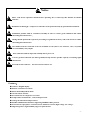
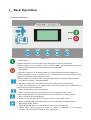
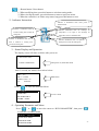
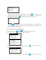
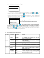
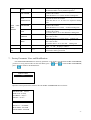
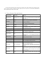
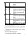
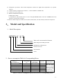
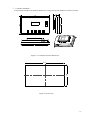
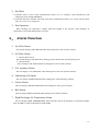
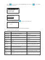
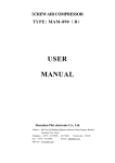
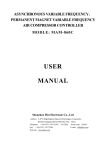
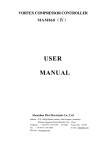
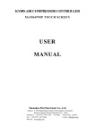
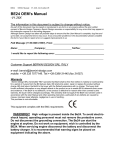
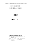
SCREW AIR COMPRESSOR CONTROLLER
MODLE: MAM-880
USER
MANUAL
Shenzhen Plot Electronic Co., Ltd
Address:4-5F,5 Bldg,Highstar Industry Park,Gangtou Community,
Bantian,Longgang District,Shenzhen City,China
Telephone:(+86 0755)83173599 / 83172822 Postal code:518034
Fax:(+86 0755)83172966
E-mail:[email protected]
Web site:www.pltsz.com
VOTE OF THANKS
Thank you for your trustworthy and select of PLOT air compressor controller !
Shenzhen Plot Electronic Co., Ltd specializes on the manufacture and R&D of air
compressor controller. We are devoted to win customer trust through our high quality
products and service.
We try our best to ensure the completeness and correctness of the manual, but
PLOT Company shall reserve the rights for continuous research and improvement on
its products and assume no obligation for the modification and improvement on the
previously delivered products. The design of products is subject to the change
without notice.
Please feel free to contact our after-sale service center if you encounter any
problem with our product.
You are always welcome to make suggestions and advices!
Notice
Please read all the operation manual before operating the set and keep this manual for further
reference.
Installation of MAM—8** compressor controller can be performed only by professional technicians.
Installation position shall be considered carefully in order to ensure good ventilation and reduce
electromagnetic interference.
Wiring shall be performed respectively according to regulations for heavy and weak current to reduce
electromagnetic interference.
RC snubber must be connected to the two terminals of coil (such as AC contactor ,valve, etc),which
are controlled by relay output.
Port connection shall be inspected carefully before power on.
Correct ground connection (the third ground)can help increase product capacity of resisting signal
interference.
Set rated current of motor: the max current of motor/1.2.
Features:
●
●
●
●
●
●
●
●
●
●
Chinese / English display.
Remote control/Local control.
Block mode/Independent mode.
On-off control of motor.
Prevention for air compressor reversion.
Temperature measurement , control and protection .
Voltage measurement and protection.
RS485 communication function, supporting MODBUS RTU protocol.
Protection for open phase, overload current, unbalance current, high voltage ,low voltage .
High integration , high reliability ,high cost performance.
-1-
Contents
1、Basic Operation ...............................................................................................................................................- 3 1、Button explanation...................................................................................................................................- 3 2、Indicator Instruction.................................................................................................................................- 4 3、Status Display and Operation ..................................................................................................................- 4 4、Operating Parameter and Menu ...............................................................................................................- 4 5、User Parameter View and Modification:..................................................................................................- 5 6、User Parameter Sheet and Function.........................................................................................................- 6 7、Factory Parameter View and Modification ..............................................................................................- 8 8、 Factory Parameter Sheet and Function ..................................................................................................- 9 9、Parameter Calibration ............................................................................................................................- 10 10、Operating Authorization and Password ...............................................................................................- 11 2、 Controller Function and Technical Parameter .............................................................................................- 12 3、 Model and Specification ..............................................................................................................................- 13 1、Model Description .................................................................................................................................- 13 2、 Power consumption Table for Corresponding Motor...........................................................................- 13 4、Installation .....................................................................................................................................................- 14 1、Mechanical Installation..........................................................................................................................- 14 2、Electrical Wiring Installation .................................................................................................................- 16 5、 Control Process............................................................................................................................................- 17 1、Single Machine ......................................................................................................................................- 17 2、Net Work................................................................................................................................................- 18 3、Fan Operation ........................................................................................................................................- 18 6、 Alarm Function............................................................................................................................................- 18 1、Air Filter Alarm .....................................................................................................................................- 18 2、Oil Filter Alarm .....................................................................................................................................- 18 3、O/A separator Alarm..............................................................................................................................- 18 4、Lubricating Oil Alarm............................................................................................................................- 18 5、Grease Alarm .........................................................................................................................................- 18 6、Belt Alarm..............................................................................................................................................- 18 7、High Discharge Air Temperature Alarm ................................................................................................- 18 7、 Controller Protection ...................................................................................................................................- 19 1、Motor Protection....................................................................................................................................- 19 2、 Protection of Air Temperature High ....................................................................................................- 19 3、Protection of Air Compressor Non-reversing ........................................................................................- 19 4、Protection of High Pressure ...................................................................................................................- 19 5、Protection of Sensor Failure ..................................................................................................................- 19 6、Low Temperature Protection..................................................................................................................- 19 8、 Troubleshooting ...........................................................................................................................................- 19 1、This Fault Review..................................................................................................................................- 19 2、Common Failures and Causes................................................................................................................- 20 9, Block mode control and net work....................................................................................................................- 21 10.Schematic Diagram.........................................................................................................................................- 24 -
-2-
1、Basic Operation
1、Button explanation
Figure 1.1.1
——Start Button:
1,When compressor is at stop status, press this button to start the compressor.
2,When compressor is set as master ( No.1 ) in block mode ,press this button to start the
compressor and activate block mode function at the same time.
——Stop Button:
1,When the compressor is at running status, press this button to stop the compressor;
2,When compressor is set as master (No.1 ) in block mode ,press this button to stop
compressor and block mode function as well;
3,When compressor is at stop status, long press this button to display software edition.
——Set Button /Loading / unloading Button:
1, When the compressor is at running status ,press this button to load, unload ;
2, When the compressor is at setting mode, press this button after modification to
confirm and save the modified data.
——Move down button / Decreasing button:
1, When viewing the menu, press this button to move downward the cursor;
2,When modifying data, press this button to decrease the data at current position.
——Move up button/Increasing button:
1, When viewing the menu, press this button to move upward the cursor ;
2, When modifying data, press this button to increase the data at current position .
——Shift button /Enter button:
1, When modifying data, press this button to move to the next data bit;
2, When select menu, press this button to switch to submenu. If no submenu
available, the controller will shift to data setting mode.
-3-
——Return button / Reset button:
1, When modifying data, press this button to exist data setting mode;
2, When viewing the menu, press this button to return to previous-menu;
3, When the controller is at failure stop status, long press this button to reset.
2、Indicator Instruction
Indicator is illuminated when motor power is
malfunctioned.
Indicator is illuminated when the
Indicator illuminated when the discharge air
air filter running time exceeds the
temperature is too high or the discharge air
setting time.
temperature sensor is malfunctioned ;
Indicator is illuminated when the oil
Indicator illuminated when oil separator
filter is blocked or running time
running time exceeds the setting time.
exceeds the setting time
3、Status Display and Operation
The display screen will show as below after power on:
WELCOME USING
SCREW COMPRESSOR
After power on, show this menu
After 5 seconds, the menu will switch as below:
AIR T:78℃
AIR P:0.60MPA
Main menu
NORMAL STOP 0S
C16
Press “
REMOTE
” to enter into Selection Menu:
RUN PARA.
USER PARA.
FACTORY PARA.
CALBR PARA.
Level 1 menu
4、Operating Parameter and Menu
Press “
” or “
” to move the cursor to “RUN PARAMETER”, then press “
to switch to secondary menu:
MOTOR、 FAN CUR
TOTAL RUN TIME
THIS RUN TIME
MAINTAIN PARA.
”
-4-
HISTORY FAULT
PRODUCTION DATE、NUM.
THIS FAULT
COM STATUS
Move the cursor to the corresponding menu item, press “
” to check the specific
parameter. Such as viewing "MOTER FAN CUR ", move the cursor to the " MOTER FAN
CUR " menu item, press the “
”, switch to the item of motor , fan data .
MAIN(A) FAN (A)
A 50.1
2.1
B 50.1
2.1
C 50.1
2.1
Press the “
” to return to the previous menu or the main menu. If no operation at the
current menu for 120 Seconds , controller will automatically return to the main menu and
turn off the backlight simultaneously.
5、User Parameter View and Modification:
In first menu, press the “
PARA." item, press the “
” and “
” to move the cursor to the "USER
” to switch to the following menu:
P、T SET
SET TIME
OPERATION MODE
BLOCKING MODE
CLR LIFE TIME
MAX LIFE TIME
LANG. LANG. SELECT CH/EN
NEW USER PIN:****
Move the cursor to the "P、T SET " item, then press “
menu:
” to switch to the following
LOAD P:00.62 MPa
UNLOAD P:00.78MPa
FAN START T:0080℃
FAN STOP T:0075℃
Move the cursor to the “LOAD P” item, then press “
” to switch to the following
-5-
menu which requires a user password input.
INPUT CODE
****
In this menu, the first data bit of password started blinking,press “
” or “
” to
modify the first bit of password.Press the “
”, move the cursor to the next data bit,
modify the second data of password. In accordance with the above, modify the third and
fourth data of password in sequence. Press“
” to confirm the input data and the menu
will switch to the following menu after verification:
LOAD P:00.62 MPa
UNLOAD P:00.78MPa
FAN START T:0080℃
FAN STOP T:0075℃
*
The upper right corner with "*
indicate the system verification of the password
In the menu above , press “
” , the first data of loading pressure starts to blink,
user can press “
” or “
” to modify the present data in accordance with the above
method .Press “
” to move to next data bit and modify to the target data in sequence.
When finished, press “
” to confirm and save the data. The controller prompt sends out
a short voice to tip the completion of parameter set .
6、User Parameter Sheet and Function
First menu
SET P. T.
TIME SET
Second menu
Preset Data
LOAD P.
00.60MPa
UNLOAD P.
00.80Mpa
FAN START
T
0080℃
FAN STOP T
0070℃
MASTER
DELAY
0008S
FAN DELAY
0006S
STAR
DELAY
0006S
Function
1,In AUTO LOADING, compressor will load if
pressure is below this set data
2,In STANDBY mode, compressor will start if the
pressure is below this set data
1.Compressor will unload automatically if air pressure
is above this set data
2.This data should be set above LOAD P ,also should
be set below ULD LIM P
Fan will start if discharge air temperature is above
this set data
Fan will stop if discharge air temperature is below
this set data
Set the master start time, record time when master is
activated, controller will not start overload protection
during this time to avoid stopping the master by
impulse starting current
Set the fan start time, record time when fan is activated,
controller will not start overload protection during this
time to avoid impulse starting current stopping the fan.
Time from star start to delta start.
-6-
OPERATION
MODE
PRESET
BLOCKING
MODE
SETTING
CLR
TIME
LIFE
LOAD
DELAY
0002S
UNLOAD
DELAY
0600S
STOP
DELAY
0010S
START
DELAY
0100S
ON/OFF
MODE
LOCAL/REMOTE
LOAD
MODE
AUTO/MANU
COM MODE
PROHIBIT
/COMP./BLOCK
COM
ADDRESS
0001
BLOCK
MODE
MASTER/SLAVE
TURN TIME
0099 Hours
BLK
NUMER
0000
BLK MIN
00.65MPa
BLK MAX
00.75MPa
BLK DELAY
0050S
0000H
OIL FILTER
O/A
SEPARATOR
AIR FILTER
LUBE
GREASE
0000H
0000H
0000H
0000H
Unloading in this set time after enter delta running
When unloading continuously, compressor will
automatically stop and enter to standby status if over
this set time
For NORMAL STOP operation, compressor will stop
after it continuously unloading over this set time
Machine can be restarted only over this set time at any
case(after NORMAL STOP, STANDBY or FAILURE
STOP )
1. When set as LOCAL, only the button on the
controller can turn on and turn off the machine.
2. When set as REMOTE mode, both the button on the
controller and the remote control button can turn on
and off the machine;
1.When set as the MANU: only when the pressure is
above “unloading pressure”, compressor will unload
automatically.
For
any
other
case,
the
Loading/Unloading function can only be executed by
pressing “loading/unloading” key.
2.When set as AUTO ,the loading/ unloading function
can be executed by the fluctuation of air pressure
automatically
1.
When-set-as-PROHIBIT,-the-communication
function is invalid.
2.When set as COMP. ,compressor function as a slave
and is able to communicate with computer or DCS
3.When set as BLOCK, compressor can net control
Set the communication ADD in block mode or when
communicate with monitoring center. This ADD is
unique for every controller in net
1. When service as master in BLOCK. Master controls
slave, the COM ADDRESS should be No.1
2.When service as slave in BLOCK, slave is controlled
by master
When master pressure is between BLOCK LOAD P
and BLOCK UNLOAD P, master determine slave work
alternatively over this set time .
Number of air compressors in block net
In BLOCK, one compressor will start or load when
pressure is below this set data
In BLOCK mode, one compressor will stop or unload
when pressure is above this set data
In BLOCK mode, when master sends two commands
continuously, second command signal delays for this
set data,
Record total running time of oil filter, if changing new
oil filter, the data should be reset by manual operation.
Record total running time of O/A separator. If changing
new O/A separator, the data should be reset by
manual operation
Record total running time of air filter .If changing new
air filter, the data should be reset by manual operation
Record total running time of lube. If changing
lubricate ,the data should be reset by manual operation
Record total running time of grease. If changing new
grease, the data should be reset by manual operation
-7-
BELT
0000H
9999H
OIL FILTER
9999H
O/A
SEPARATOR
9999H
MAX LIFE
TIME
PRESET
AIR FILTER
9999H
LUB
9999H
GREASE
9999H
BELT
LANG.SEL
EN/CH
NEW USER
PIN
****
EN
****
Record total running time of belt. If changing new belt,
the data should be reset by manual operation
1, Alarm prompts when total running time of oil filter
is above the set data .
2,Set this data to “0” to clear oil filter running time
1, Alarm prompts when total running time of O/A
separator is above the set data.
2,Set this data to “0” to clear O/A separator running
time
1, Alarm prompts when total running time of air filter
is above the set data.
2,Set this data to “0” to clear air filter running time
1, Alarm prompts when total running time of lubricate
is above the set data.
2, Set this data to “0” to clear lubricate running time.
1, Alarm prompts when total running time of grease is
above the set data.
2,Set this data to “0” to clear grease running time
1, Alarm prompts when total running time of belt is
above the set data.
2, Set this data to “0” to clear belt running time .
1,Set to “EN” , Display in English
2,Set to “CH” , Display in Chinese
User could modify the user password by old user
password or factory password
7、Factory Parameter View and Modification
FACTORY PARAMETER store relatively parameter set by factory. To check FACTORY PARAMETER,
you have to verify password first. In the first menu, press “
press “
”to switch to the menu below.
” and “
” to FACTORY PARAMETER,
INPUT CODE
****
Input the correct password to switch to the FACTORY PARAMETER menu as below:
MOTOR CUR:100.0A
FAN CUR:010.0A
ALARM T:0105℃
STOP T:0110℃
STOP P:00.90MPa
MAX U.L.:00.85MPa
RUN TIME:001234H
LOAD TIME:001001H
-8-
………
For more factory parameter, please check factory parameter sheet. When modify factory parameter, please
refer to customer parameter modification method, supper-password is required to set TOTAL RUN TIME,PHASE
PROT,POWER FREQ and MAX RUN TIME.
8、Factory Parameter Sheet and Function
PARAMETER
Initial Data
MOTOR CUR
Maximum motor overload
data /1.2
FAN CUR
Maximum fan overload
data/1.2
ALARM T.
105℃
STOP T.
110℃
STOP P.
1.00MPa
MAX U.L.
0.80MPa
RUN TIME
LOAD TIME
000100Hours
000095Hours
CLR FAULT
****
CUR UN.BAL.
0006
OPEN PAHSE
002.0s
PROD DATE
PROD NO
****-**-**
********
PHASE PROT..
ON/OFF
POWER FREQ
50HZ/60HZ
BLK MODE
ADV/COMPATIBLE
HIGH VOL.
0460V
LOW VOL.
0320V
Function
When the current of motor is more than 1.2 times of
the set data , the unit will stop for overload feature.
(see table2.1.1)
When the current of fan is more than 1.2 times of the
set data , the unit will stop for overload feature.
When discharge air temperature reaches this set data,
compressor will alarm
When the discharge air temperature reaches this set
data, compressor will alarm and stop
When pressure reaches this set data ,compressor will
alarm and stop
This data is the maximum of UNLOADING P. The
UNLOADING P in the customer parameter must be
set no higher than this data.
Modify the TOTAL RUN TIME
Modify the TOTAL LOAD TIME
Input the password 8888 and press “set “button to
clear all the history failure record.
MAX-MIN >= SET*MIN/10 ,respond time is
5s
If the set data ≥ 15, the unbalance protection will
be invalid.
If OPEN PHASE protection ≥20 seconds, OPEN
PHASE protection is invalid
Production date
Product serial No.
ON: turn on phase sequence protection
OFF: turn off phase sequence protection
Set the operation power frequency
Set as compatible mode, block mode is the same as the
other series controller by PLOT
When block control with MAM 8*0 controller and set
as advanced mode, more block mode function is
available
1, Controller detects the voltage higher than this set
data, the shutdown protection starts and reports HIGH
VOL.
2,Set this data to 0000, the HIGH VOL. protection
function is invalid
1,Controller detects the voltage lower than this set
data, shutdown protection starts and reports LOW
VOL.
-9-
LOW T PRO-
-0048℃
TIME LIM
0000H
ALM STOP
0010H
COM SET PARA
ON/OFF
PARA1
****
2,Set this data to 0000, the LOW VOL. protection
function is invalid
1,In stop mode, air compressor is not allowed to start
when discharge air temperature is lower than this set
data
2,Two minutes after turn on, when the air temperature
is below this data, compressor will stop and display
T SENSOR FAULT
1,When the compressor is in a stop status and the
TOTAL RUN TIME exceeds this TIME LIM set, the
controller will stop the compressor and display USER
MISTAKE;
2,If this data is set to ‘0000’, TIME LIMIT function is
invalid.
Controller detects oil filter, O/A separator, air filter,
lubricate oil ,grease and belt running with alarming
over this ALARM STOP set, compressor will stop and
report ”ALARM LONG STOP ”
1,When set as ON, User can use DCS to set data
through MODBUS protocol;
2,When set as OFF, User cannot use DCS to set data
through MODBUS protocol
3,User can use DCS to set data only when compressor
is at stop status
User could modify the factory password by old factory
password.
9、Parameter Calibration
You can set relative data of controller in CALBR PARA. It is not allowed to view and modify without
manufacturers authorization, so please verify the password before view and modification. The
modification of CALBR PARA is similar with CUSTOMER PARA. Main function is shown as below.
PARAMETER
M
O
T
O
R
A
M
O
T
O
R
B
Initial Data
TARGET CUR
0000
COEF
1.000
CUR
***.*A
TARGET CUR
0000
COEF
1.000
CUR
***.*A
Function
1,When calibrate the current of motor A, revise
standard current data, controller calibrate the current
by figuring the current coefficient and save the data
automatically
2,Standard current data will return to zero after
calibration
When calibrate the current, revise coefficient.
Current data in display=sample data*coefficient
This data is qret
1,When calibrate the current of motor B, revise
standard current data, controller calibrate the current
by figuring the current coefficient and save the data
automatically
2,Standard current data will return to zero after
calibration
When calibrate the current, revise coefficient.
Current data in display=sample data*coefficient
this data is qret
- 10 -
M
O
T
O
R
TARGET CUR
0000
COEF
1.000
CUR
***.*A
F
A
N
TARGET CUR
0000
A
COEF
1.000
CUR
***.*A
C
F
A
N
TARGET CUR
0000
COEF
1.000
CUR
***.*A
TARGET CUR
0000
COEF
1.000
CUR
***.*A
B
F
A
N
C
1,When calibrate the current of motor C, revise
standard current data, controller calibrate the current
by figuring the current coefficient and save the data
automatically
2,Standard current data will return to zero after
calibration
When calibrate-the-current, revise coefficient.
Current data in display=sample data*coefficient
this data is qret
1,When calibrate the current of fan A, revise
standard current data, controller calibrate the current
by figuring the current coefficient and save the data
automatically
2,Standard current data will return to zero after
calibration
When calibrate the current, revise coefficient.
Current data in display=sample data*coefficient
this data is qret
1,When calibrate the current of fan B ,revise
standard current data, controller calibrate the current
by figuring the current coefficient and save the data
automatically
2,Standard current data will return to zero after
calibration
When calibrate the current, revise coefficient.
Current data in display=sample data*coefficient
this data is qret
1,When calibrate the current of fan C ,revise
standard current data, controller calibrate the current
by figuring the current coefficient and save the data
automatically
2,Standard current data will return to zero after
calibration
When calibrate the current, revise coefficient.
Current data in display=sample data*coefficient
this data is qret
10、Operating Authorization and Password
Controller provides multiple passwords and access management. According to different
levels of passwords, controller provides different levels of operating authorization, details as
following:
1、User operation password: fixed:___________
Permissions: allows to modify the LOADING P, UNLOADING P, FAN START T, FAN START T,
ON/OFF MODE, LOAD MODE, COM MODE, COM ADD and BLOCKING MODE.
2、New user password: factory set:___________
Permissions:Allows to modify all CUSTOMER PRAMETER.
3、Manufacturer sales password: factory set:___________
Permissions: Allows users to modify all CUSTOMER PRAMETER, the NEW USER PIN, some
MANUFACTURER PARAMETER, MANUFACTORY SALES PASSWORD.
- 11 -
4、Manufacturer operation Password: fixed:___________
Permissions: Allows users to modify all CUSTOMER PRAMETER, the NEW USER PIN, some
MANUFACTURER PARAMETER, MANUFACTORY SALES PASSWORD.
5、Calibrate Password: fixed:___________
Permissions: Allows users to calibrate currents in CALBR PARAMETER.
6、Super Password: fixed:___________
Permissions: Allows users to modify TOTAL RUN TIME,PHASE SEQUENCE PROTECTION,
OPWER FREQUENCY ,TIME LIMIT after user enter factory parameter and verify supper
password.
2、 Controller Function and Technical Parameter
1、Digital input: 3 points of digital input ;5 points of digital relay output ;
2、Analog input: 1 point of Pt100 temperature input ; 1 point of 4~20mA pressure signal input; two groups of
three phases current inputs(CT provided);
3、Input voltage of phases:380V/220V;
4、Compressor protection of high operation voltage and low operation voltage
5、Controller working power supply:AC20V、30VA
6、Measurement :
①、Discharge air temperature:-50~150℃;Accuracy:±1℃.
②、Operation time: 0~999999 hours.
③、Current:0~999.9A.
④、Pressure: 0~1.60MPa. Accuracy: ±0.01Mpa.
7、Phase sequence protection: When compressor is at stop mode and detects wrong phase sequence, respond
time≤1s (optional);
8、Open phase protection: When compressor is at stop mode and detects open phase ,respond time≤1s
9、Motor protection : This controller has basic protection function for main motor and overload protection
for fan.
①、Open phase protection:When any phase opens, the respond time equals to set time, when phase open
time is set above 20s,open phase protection is invalid;
②、Unbalance protection: when MAX-MIN >= SET*MIN/10 ,respond time is 5s;
③、Protection features of overload (time unit: second),please see following table(table 2.1.1),multiple
=Iactual/Iset ,motor operates with delay time according to overload multiples and operation time
shown in following table (table 2.1.1) when motor working current is higher or equal to the set current
from 1.2 times and 3.0 times .
Iactual/Iset
≥1.2
≥1.3
≥1.5
≥1.6
≥2.0
≥3.0
60
48
24
8
5
1
Time parameter
Response time(S)
Table 2.1.1 curve table for protection of motor
- 12 -
10、Temperature protection: when actual temperature measured is higher than temperature set; response
time≤2s;
11、Contact capacity of output relay: 250V,5A;Contact endurance :500000 times
12、Current error is less than 1.0%.;
13、RS485 communication function
1,Block mode control
2, Communicate with-external devices as slave through MODBUS RTU, baud rate 9600BPS,1start bit,8
data bits,1 stop bit and even parity
14. Remote control compressor: When set as remote control mode, user can remotely control the compressor.
3、 Model and Specification
1、Model Description
MAM 880(B)(T)(V)(40)
Max work current match with motor
With voltage detection& protection
With RS485 communication
Pressure converter
880 controller
Series
2、Power consumption Table for Corresponding Motor
Parameter
Specification
MAM880(20)
MAM880(40)
MAM880(100)
MAM880(200)
MAM880(400)
MAM880(600/5)
Current range
(A)
8~20
16~40
100
200
400
600/5
Corresponding
main motor
power (KW)
Below 11
11-18.5
22-45
55-90
110
200-250
Remark
Description
With CT
Fan has three
levels of current,
such as 0.2-2.5A,
1-5A and 4-10A,
determined-by
current of motor
Table 3.2.1 Power consumption specification sheet for corresponding motor
- 13 -
4、Installation
1、Mechanical Installation
①、 Current transformer installation
The CT shall be installed at a place where the current of motor cable can be measured, thus controller
can be set according to instructions on motor nameplate, the detailed dimensions is shown as below:
A
B
Figure 4.1.1. Structure dimensions of CT1(ф36 through hole)
Figure 4.1.2.
Installation dimensions of CT1
A
B
Figure 4.1.3. Structure dimensions of CT2 (ф10 through hole)
Figure 4.1.4. Installation dimensions of CT2
- 14 -
②、Controller installation
A certain room should be left around controller for wiring. The specific dimension is shown as below:
Figure 4.1.5 Controller structure dimension
139
239
Figure 4.1.6 Hole size
- 15 -
2、Electrical Wiring Installation
A
RS-485
B
FG
10 9 8 7 6 5 4 3 2 1
C1
21 20 19 11 12 13 14 15 16 17 18
uc ub ua
22 23 24 25 26 27 28 29 30 31
△
、
a
b
CT2
c
A
B
CT1
C
Figure 4.2.1 Terminal arrangement diagram
Cable connection of controller:
1
4
7
10
13
16
19
22
25
28
31
Common terminal for digital
input
Input terminal used to detect
oil filter
RS485-
2
Input terminal for emergency
stop signal
N/A
3
9
11
Terminal for ground
connection
N/A
12
Terminal for the AC20V
power source
N/A
Terminal for the AC20V
power source
Common terminal for digital
output
Terminal to control delta
contactor
Input terminal to detect the
phase sequence and voltage
Power terminal for pressure
sensor
Terminal for motor CT1
input
Terminal for fan CT2 input
Terminal for AIR T
14
Terminal to control fan
15
Terminal to control load valve
17
18
26
Terminal to control star
contactor
Input terminal to detect the
phase sequence and voltage
Input terminal to receive
pressure sensor signal
Terminal for motor CT1 input
27
Terminal to control main
contactor
Input terminal to detect the
phase sequence and voltage
Terminal for motor CT1
input
Terminal for fan CT2 input
29
Terminals for fan CT2 input
30
Terminal for AIR T
5
8
20
23
6
21
24
Input terminal for remote
control signal ( on/off )
RS485+
- 16 -
5、 Control Process
1、Single Machine
1, Working principle(On/off mode: Local; Load mode: Auto)
①. Press “
”to start: (Y-△start)
The air compressor can not be started by pressing “
“until 5 seconds self checking finished. The
start process of compressor is as followed: 18 terminal closed, KM2 is energized;17 terminal
closed ,KM3 is energized → Y start → STAR DELAY time starts record; when Y-△transfer time
over,17 terminal open ,KM3 is de-energized and 16 terminal closed,KM1 is energized → motor
operates in △ . (KM1 and KM3 are interlocked)
②. Automatic operation control:
A, When motor enter delta status, LOAD DELAY starts, controller will load automatically after
LOAD DELAY.
B, If air pressure is detected higher than UNLOADING P set,15 terminal opens, loading valve is
de-energized, and air compressor starts unloading, and also starts EMPTY LONG STOP time record ,if
unloading time exceed EMPTY LONG STOP set, compressor will enter STANDBY mode; if
compressor loading again within “EMPTY TIME” set(when pressure is below LOADING P or
receiving load command),compressor will reset “EMPTY LONG STOP”.
C, In STANDBY mode, controller start automatically if pressure detected is below LOADING P
③. Manual loading/unloading operation under automatic status
A: When air pressure is between LOADING P and UNLOADING P, press “loading/ unloading” to
switch the current status of controller.
B, When air pressure is above the UNLOADING P, controller unloads automatically, the
loading/unloading button is invalid
C, When air pressure is below the UNLOADING P, controller loads automatically, the
loading/unloading button is invalid
④. Normal stop:
Press “
” , the loading magnetic valve will be de-energized, after a while of delay (stop delay),
all output relay stop working.
⑤.The frequent starting control
Air compressor can not start again immediately after NORMAL STOP ,EMPTY LONG STOP or
FAILURE STOP. It can start again after START DELAY.
2, Remote Automatic Control (Control Mode: Remote; Load Mode: Auto)
In this mode, compressor can be turned on or off by remote control.
3, Local Control (Control Mode: local, Load Mode: Manual)
A, Control of start and stop are same as automatic control, but device is in status of unloading after
finish starting process.
B, In unload status, press “
” to load. When air pressure is higher than UNLOADING P set, the
device will unload automatically.
C, If not press “loading/ unloading”, the device will run unload until EMPTY LONG STOP.
D, In load status, press “
” to unload.
- 17 -
2、Net Work
①.Controller works as slave when communication mode is set as” computer”, and communicates with
monitoring center through MODBUS.
②.Controller and other controller can block work when communication mode is set “block” but the master
only can service as 1# compressor.
3、Fan Operation
When discharge air temperature is higher than FAN START T, fan operates; when discharge air
temperature is lower than FAN STOP T, fan stops.
6、 Alarm Function
1、Air Filter Alarm
The monitor displays AIR LIFE END when the running time of the air filter exhausts.
2、Oil Filter Alarm
①. Oil filter block check.
The monitor displays OIL BLOCK by checking pressure differential switch-operating state.
②. Oil filter alarm
The text displays OIL LIFE END when running time of the oil filter exhausts.
3、O/A separator Alarm
The text displays “O/A LIFE END” when running time of the O/A separator exhausts.
4、Lubricating Oil Alarm
The text displays LUBE LIFE END when running time of the lubricating exhausts.
5、Grease Alarm
The text displays GREASE LIFE END when running time of the grease exhausts.
6、Belt Alarm
The text displays BELT LIFE END when running time of the belt exhausts.
7、High Discharge Air Temperature Alarm
The text display HIGH TEMPERATURE when controller detects the discharge air temperature higher
than ALARM T set data in MANUFACTORY PARA.
- 18 -
7、 Controller Protection
1、Motor Protection
MAM-880 air compressor controller provides overload, open phase, current unbalance, high voltage, low
voltage protection for motor and overload protection for fan
Electronic
Failure Display
Reason
failure
Overload,-bearing-wear-and-other-mechanical
Overload
Display “MOTOR/FAN OVER LOAD”
failure
Power supply, contactor and open phase of
Open phase Display “MOTOR OPEN PHASE”
motor
Poor contact of contactor, inside open-loop of
Unbalance
Display-“MOTOR-UNBLANCE”
motor
High
Display“ HIGH VOLTAGE”
High supply voltage
voltage
Low
Display “LOW VOLTAGE”
Low supply voltage
voltage
2、Protection of Air Temperature High
When discharge air temperature is above the high limit of set temperature, the controller will send out the
alarm to shut down the machine and This fault displays HIGHT T.
3、Protection of Air Compressor Non-reversing
When compressor stops and three-phases sequence is not in order, THIS FAULT displays PHASE
REVERSAL, and the controller cannot start the motor. Change the position of any arbitrary two-phase
power lines and check the rotation of motor.
4、Protection of High Pressure
When the discharge air pressure is above the MAX LIM P, the controller will send out the alarm to shut
down the machine and THIS FAULT displays HIGH P.
5、Protection of Sensor Failure
When pressure sensor or temperature sensor is disconnected, the controller will send out the alarm to shut
down the machine and THIS FAULT displays **SENSOR FAULT.
6、Low Temperature Protection
When discharge air temperature is below LOW T PRO in manufacturing parameter, THIS FAULT displays
P SENSOR FAULT two minutes after compressor turns on, the controller will send out the alarm to shut
down the machine .
8、 Troubleshooting
1、This Fault Review
Failure stop caused by the external parts of controllers may be removed by checking THIS FAULT or
HISTORY FAULT , method is shown as below:
- 19 -
Press “
”to move the cursor to “RUN PARAMETER” menu, then press “
menu would be prompted out:
” , the secondary
MOTORS /FAN CURRENT
TOTAL RUN TIME
THIS RUN TIME
CLR LIFE TIME
HISTORY FAULT
PROD DATE NO.
THIS FAULT
COM STATUS.
Move cursor to THIS FAULT press “
” to switch to the following menu:
STOP:T SENSOR FAULT
0170℃
User can reset the error according to the following information
2、Common Failures and Causes
Failure
Reason
Solution
AIR T High
Bad vent condition, Oil shortage etc.
Check the vent condition and lubricant
amount etc.
Temperature
Sensor Failure
Cable off or PT100 failure
Check the wiring and PT100
AIR P HIGH
Pressure too high or the pressure sensor failure
Check the pressure and the pressure
converter
Pressure Sensor
Failure
Cable off, Sensor failure or the cable connect
reversed
Check the
converter
Open Phase
Overload
Unbalance
Wrong Phase
Sequence
Overload during
start
Main Contactor
shakes
frequently
Power open phase or the contactor terminal
failure
Voltage too low, tubes block, bearing wear off
or other mechanical failure or wrong set data
etc.
Power unbalance, contactor failure or the
internal open loop of the motor
wiring
and
pressure
Check the power and contactors
Check the set data, voltage, bearings,
tubes and other mechanical system.
Check the power, contactor and the
motor
Reversed phase sequence or open phase
Check the wiring
Master start time set to less than the star delta
delay time
Reset the master start time to be longer
than star delta delay + 2 seconds
Check the wiring; if the coil of
contactor connect with surge absorber
or not
The emergency button loose, controller reset by
interference
- 20 -
9, Block mode control and net work
1. Block mode control
① Block control explanation
MAM880 controller can block operate with MAM series compressor (with communication function).16 pcs
compressors are allowed in the net at most. The cable connection for block mode control is as below....
............
A
B
一号机
Master
No.1
A
B
A
二号机
Slave
No. 2
B
Slave
No. 3
A
B
Slave
No. 4
A
B
Slave
No. N
Picture 9.1.1
Compressor with net communication address 0001 is master, others are slave. Any one MAM series
compressor can be set as master or slave.
② Block mode setting
1. Set as master:
In main menu, press “
” to enter select menu and choose USER PARAMETER, press “
” and switch
to the menu below:
SET P,T.
SET TIME
OPERATION MODE
BLOCKING MODE
Move the cursor to OPERATION MODE, press “
” to switch to the menu below.
ON/OFF MODE:REM
LOAD MODE :AUTO
COM MODE :BLOCK
COM ADD :0001
- 21 -
Set COM MODE as BLOCK,COM ADD as “0001”,return to the previous menu ,move the cursor to
BLOCKING MODE press “
” to switch to the menu below
BLK STATE: MASTER
ALTER TIME:0002H
BLK NUMER.:0004
BLK MIN:00.62MPa
BLK MAX:00.78MPa
BLK DELAY:0020s
According to user requirement, set BLK STATE as MASTER, set ALTER TIME,BLK NUMER,BLK
MIN,BLK MAX,BLK DELAY according to user’s need .After-setting ,controller-needs to be powered off and
restarts to the setting.
2.Set as slave:
When MAM controller serves as slave ,it is only necessary to set COM MODE as BLOCK mode, set COM
ADD from2-16 with sequence according to the quantity of compressors, .BLK STATE set as SLAVE.
③、Start ,stop block control:
Make sure block cables connect correctly and the parameter of compressors in net set correctly. Activate
master, master controls the compressors in net automatically according to the air pressure detected . Block
control stops at the same time when manually stop the master so master will no longer send command to
compressor in net .
Discharge air TEM: 78℃
◇
Air pressure:
0.53MPa
NORMAL STOP 0s
C16
remote control
◇ Blinking icon indicate master
has activate block mode function
④、Block communication receiving and sending message:
The message received and sent by RS485 can be displayed by the corresponding indication screen which is
convenient for customer to make sure if they have received and feedback data in BLOCK mode or COM MODE.
The method to switch to communication menu is as below: press “
” in main menu and enter main menu and
select run parameter and move down the cursor to communication menu, press “
” and switch to the COM
MODE menu as below
RX:—
TX:—
- 22 -
When controller receives data, RX:“— ”and“*”display alternately, When sends data, TX:“— ”and“*”display
alternately. When controller is in block control or communicates with monitoring center ,user can confirm the
establishment of communication through this menu.
2.Net Work
MAM880 controller supports MODBUS RTU protocol and can serve as slave when connect with other equipment
and supports 03、06、16 MODBUS command. Communication baud rate:9600BPS, 1 start bit, 8 data bits, 1 stop
bits and even parity. For MODBUS register address, please see MODBUS communication manual.
- 23 -
RS-485
FG
A
B
21 20 19 11 12 13 14 15 16 17 18
uc ub ua
22 23 24 25 26 27 28 29 30 31
C1
10 9 8 7 6 5 4 3 2 1
10.Schematic Diagram
a
b
c
A
B
C
- 24 -