1
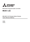
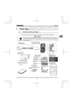
 AVR
Industrial‐Grade High Efficiency A.C Voltage Regulator USER’S MANUAL OPTI‐UPS International Corporation reserves the right to make engineering changes on all its products. Such refinements may affect information given in the instructions. Therefore, USE ONLY THE INSTRUCTIONS THAT ARE PACKED WITH THE PRODUCT. WARNING: High voltages are present inside this unit during operation. Do not operate this unit unless all covers are in place. Installation and servicing should only be done by qualified personnel. - 1-
CONTENTS 1‐ The Protection and Maintenance of AVR 3 2‐ Safety warnings 4 3‐ Description of the symbols used in this manual 5 4‐ Introduction 6 5‐ Functions Introduction 7 6‐ Preliminary warnings to use the AVR 7~8 7‐ Operating procedures 8~9 8‐ The Operation Procedures of Maintenance By Pass Switch 10 9‐ Maintenance & Cleaning 10~11
10‐ Trouble shooting Guide 11 11‐ Storage 11 12‐ Technical specifications 12 13‐ Machine schematic view/outline 12~19
- 2-
1‐ The Protection and Maintenance of AVR 1. Please clean and maintain the AVR periodically to keep from dust for lasting machine life. 2. Please use soft cloth for wiping, and please don’t use sandpaper as detergent. 3.Please check every kind of connection wires every month periodically to prevent the loosing or abrasion. 4. Please place the unit on a flat or even surface. 5.This unit should be situated with well‐ventilation, please allow at least 30 cm clearance from the rear front, left and right side, and these ventilation openings of right and left front , and rear line should never be blocked. 30cm
6. Please avoid the direct sunshine, rain or moisture place. 7. Keeping the unit away from fire and high temperature to avoid overheat. 8. Please don’t place any object on the top. 9. Avoiding the installing place that contains the corrosion gas. 10. Operating temperature is between 0℃ ~ 40℃. - 3-
2‐ Safety warnings For the user’s own safety, the safety of data and this product read the following safety instructions carefully before using the unit! ‐ This system has been designed to provide all the necessary safety conditions needed to protect electronic office equipment including information systems. In case of any questions, refer to your authorized technical service representative. ‐ In order to avoid any damage to the equipment, it is advised to transport it in its own packing. ‐ In the event of sudden temperature changes such as from cold to the normal working temperature, mist can form inside the AVR. It is absolutely essential that the AVR be dry before switching it on. Due to this reason wait for at least 2 hours before operating it. ‐ Once dry, make sure you observe all the conditions in the environment section of the technical specifications table, before introducing it into the circuit. ‐ When installing the AVR it is necessary to use a connection cable of suitable diameter. The point to be noted here is that the neutral and the earthing connections should be done in the proper way. ‐ Place all the cables in a proper place so that they are not stepped on or get caught into peoples feet. Before connecting the AVR to the circuit make sure you carefully read all the instructions and warnings in the“Montage and Operating Procedures“ section of this manual. ‐ Don’t drop any foreign materials (like clips, nails etc...) into the equipment. ‐ In emergencies (damage to the cabin, front panel, or mains connections,splashing of liquid dropping of any foreign materials into the equipment) switch‐off the AVR, pull out the plug and inform the authorized service center. ‐ The AVR can only be repaired by the authorized technical service personnel. Any attempt to open and to repair by the user on his own could prove to be dangerous. ‐ Do not connect any consumer loads to the AVR, which exceed its power range. ‐ Read the instructions carefully in the “The Operation Procedures of Maintenance By Pass Switch” & “Cleaning” section when cleaning the AVR. ‐ Leave at least a distance of 45 cm between the AVR and the walls in order to maintain adequate air‐flow . - 4-
3‐ Description of the symbols used in this manual The following symbols have been used in this manual. This symbol gives information regarding points important for user’s own health and safety, AVR operation and the safety of your data. This symbol gives information, warnings, and other suggestions. This symbol shows the operations that need to be executed. - 5-
4‐ Introduction Input power is applied across the motor driven variable transformer which has a “center tap” that divides the variable transformer into bucking and boosting voltage areas.The buck‐boost transformer is a fixed ratio isolation transformer capable of high amperes at low voltage. The ratio of the buck‐boost transformer is determined by the amount of voltage needed to buck or boost the input line voltage to maintain the specified output level. The buck‐boost transformer secondary is wired in series with the load and the primary is connected across the variable transformer’s “center tap” and brush terminals.Depending on which side of the “center tap” the variable transformer brush is positioned, the variable/buck‐boost transformer system will add to (boost) or subtract from (buck) the input line voltage. The further the variable transformer brush is from the “center tap” the more bucking or boosting of voltage will occur.The key to the proven reliability and long trouble free service life of a Voltage Regulator is in the combination of a motor driven variable transformer with buck‐boost transformer technology. Buck-Boost transformer
Variable transformer
Input Output M
Controller
Figure 1. Single phase regulator block diagram As shown in figure 1, the only active component in the main power path of the voltage regulator is the secondary of the buck‐boost transformer. This gives the regulator the advantage of being able to withstand substantial current overloads.The variable transformer brushes, which are the most vulnerable component in any variable transformer system, are completely isolated from overload conditions by the buck‐boost transformer. Due to transformer inefficiency above rated design, the amount of current that the buck‐boost transformer can induce across to its primary winding and into the variable transformer circuit is dramatically decreased as regulator overload current increases. The controller monitors the regulator’s output voltage and then uses these feedback signals to determine drive commands for the variable transformer motor interface circuit. The controller is designed to adjust the motorized variable transformer to provide a +/‐1~2% or better output voltage regulation over the entire input voltage range. 5‐ Functions Introduction - 6-
MCCB1: Mold cast circuit breaker Main power switch MCCB2: Mold cast circuit breaker Maintenance bypass switch. Please remember that MCCB2 is used only for service technician. Non‐maintenance personnel must not open it to use, otherwise, AVR could be break down because of improper operating. On push switch (red button): Controlling the output (On) action. Off push switch (green button): Controlling the output (Off) action. Off (0): AVR no action, so the output has no voltage stability function. On(1): AVR action, so the output voltage is steady. Voltage and current indicator: (There is no voltage & current meter indication below 50KVA). Voltage meter (V) indicates the output voltage. Voltage selector indicates per phase( U V W) with N the output voltage. 6‐ Preliminary warnings to use the AVR Automatic Voltage Regulator (AVR) are used to protect the sensitive loads from the unstable mains and to provide proper operating of the load. Related points for human health are mentioned in “Safety Warnings” part of this manual. In this part, these points will repeated to give information about the connections of AVR and the load. • When installing the AVR to use cable with improper diameter can be dangerous for user health and safety of the unit. • Earth cable should be chosen concerning the current capacity, which is written on the label on the front panel of the AVR. All units earth connections, which are connected to AVR, should be done with this earth cable. Without earth, connection or unproved earth connected units are dangerous for user health and have high risk of electronic circuit board faults. The operation environment and cable connection plays very important role to the function of AVR. It will cause very direct and critical effect to the AVR’s MTBF. Therefore - 7-
it is essential to follow the instructions of installation and cable connection.
Requirement of operation environment: The operation environment plays a vital role for an AVR , both the function and the endurance of AVR will all be easily affected if the environment does not meet its requirement listed below: 1. Ambient temperature:0℃ ~ 40℃. 2. Keep off the oil and the salt. 3. Keep off dust, fluff and metal dust. 4. Avoid installing on a vibratory machine. 5. If AVR is installed inside a machine or a panel cabinet, the ventilation is very important, the best is to add cooling fan. 6. Do not place anything on top of the AVR. Cable Connection 1. The installation standard varies with the different models, different capacities as well as the different voltage, please refer to the appropriate installation standard provided in this manual to install your AVR and put attention to the right cables used for installation. 2. Please use a separate AC input Breaker for AVR and a closer distance to the AC power is recommended. 3. Be sure to check the right polarity while connecting cables to terminals, no matter the AVR is a single phase or three phase. 4. The utmost importance to install a three phase AVR is to mark sure of the right phase order. 5. For safely consideration, it is strictly forbidden to install with AC power “On” status. 6. Cable assembling must be completely in accordance with the electrician rules. 7‐ Operating procedures Check if the AVR has been subjected to any damage before unpacking it. If you notice any damage then contact to transport firm. Check if all the spare parts have been supplied with the AVR. Checking the input power is correct or not, then closing all switches (including every load). Delivered pack includes: - 8-
• Automatic Voltage Regulator • User Manual By the help of rolling wheels, carry the unit to a suitable location to install it. Plug the input power cable of AVR to properly earthed mains. Check the connections before changing the position of the input, output, and bypass switches to suitable positions. Proper operation procedure makes AVR function more smooth and prevent from various unnecessary troubles. Before switch on(initial start) In order to perfect the AVR normal function, please check the followings in advance: make sure MCCB(1)、MCCB(2) Mold cast circuit breaker is in “Off” status. make sure all of the load’s Mold cast circuit breaker are in “Off” status. make sure all the cables are fixed tight in the terminal and do not come loose. check with a multi‐meter for the right AC voltage to suit for AVR. After all the above are well confirmed, please take the following steps to switch On and Off: 1. to switch on: □ Switch MCCB(1) Mold cast circuit breaker up to “On” position. □ Pushing the red button “On” on front panel □ If the red button indicator is lighted, meaning the O/P voltage meter showing the right output voltage value. □ Using Ture RMS voltage meter to measure the O/P N, U V W on the terminal board. If the output voltage is correct, AVR is activated successfully. □ please not to overload your AVR 2. to switch off: □ Close Mold cast circuit breaker “Off” of every load. □ Pushing the green button “Off” on front panel, although there is no output voltage, the AVR is still in action. □ Switch MCCB(1) Mold cast circuit breaker to “Off” position. 8. The Operation Procedures of Maintenance By Pass Switch - 9-
Maintenance By‐pass : □ Close Mold cast circuit breaker “Off” of every load. □ Pushing the green button “Off” on front panel, although there is no output voltage, the AVR is still in action. □ Switch MCCB(1) Mold cast circuit breaker to “Off” position. □ Switch MCCB(2) Mold cast circuit breaker up to “On” position. □ Using Ture RMS voltage meter to measure the O/P N, U V W on the terminal board, if the output voltage is correct, AVR is by‐pass successfully. 9‐ Maintenance & Cleaning Do the cleaning during the input Mold cast circuit breaker MCCB(1) and maintenance by‐pass MCCB(2) switch is in “Off” position for human health. Do not use detergents or any cleaning material that may damage the cabinet surfaces. Do not let any liquid get into the AVR. Ensure that the air holes are open. The AVR body can be wiped with a clean and dry cloth. Check the area surrounding the AVR. Ensure the area is not cluttered, allowing free access to the unit. Ensure the air intakes (vents on the front doors) and exhaust opening (on rear of the AVR cabinet sections) are not blocked. To ensure maximum life of the equipment,the following should be part of an annual maintenance program.Warning De‐energize unit before performing maintenance.Voltages are present inside this unit which can cause injury.Therefore,only personnel qualified to service electrical equipment should perform maintenance on this unit. ‐Vacuum the voltage regulator inside and out to remove accumulated dirt, which could lead to overheating or insulation failure. ‐Tighten all electrical connections,particularly all power wiring to,and in,the unit. ‐Inspect all variable transformer brushes and commutators for signs of wear or pitting. Replace as required.Do not attempt to clean a commutator with an abrasive such as sandpaper or a file. This will ruin the soft precious metal plating on the commutator and will shorten the life of the unit. It is normal for commutators to become black due to carbon brush tracking. If a commutator is to be cleaned,use denatured alcohol and a soft cloth. - 10-
‐Inspect the variable transformer drive belts, sprockets, gears, cams, etc. for signs of slippage or wear and adjust as required. ‐Check the variable transformer radiator(s) (the die cast part that holds the brush assembly) for signs of slippage, and see if all brushes driven by the same motor are aligned with each other. The alignment of the radiator and brushes depends on the setscrews that hold the variable transformer center tube(s) to the shaft and the setscrews that hold the radiator to the center tube. Adjust and tighten as needed. ‐Lubrication of the AVR is not required since it has been lubricated at the factory for its lifetime. 10‐ Trouble shooting Guide If any errors of faults are observed on the AVR, make sure you check the following points before informing the authorized technical service: • Does the distribution panel have mains connection? • Have the protection fuses blown off? Informing the authorized service about the AVR: • Information found on the product label (model, no) • Describe the problem in detail. 11. Storage The unit has to be stored in a dry place between 0℃ ~ 90℃. - 11-
12. Technical specifications Input Characteristics Capacity: 45 KVA Voltage Range: 380Y/220 Volt, +15% to ‐ 15% at 50 Hz for regulation. Phases: Three phases‐4 wire ,Wye connection(R,S,T,N,G) Frequency Range: 47‐53Hz for 50Hz models +/‐3Hz Termination terminal block terminal board Output Characteristics Voltage: 380Y/220 Volt Phases: Three phases‐4 wire ,Wye connection(U,V,W,N,G) Voltage Range: Regulated to ±1~2% of nominal voltage with an input voltage range of +15 to –15% Frequency Range: 50Hz, for every 1% change in input frequency the output voltage will change by 1% in the same direction. Load Regulation: 5%, no load to full load Harmonic Distortion: non Efficiency: 97% at full load. Overload: For 1 minutes 100%,for 30 minutes 125%,for 60 minutes 100%. Wav e form: Sinewave Insulation Resistance: 5 megaohms from winding to core measured at 500Vdc Technology: This technique usesthe combination of a motor driven variable transformer with buck‐boost transformer technology. By‐pass Switch input power directly to load, bypassing the voltage regulator. Cooling: fan assisted Termination terminal board Environmental Audible Noise: Less than 65 dBA at 1.5 metre Ambient Temperature: 0° to 40 °C Operating, 10° to 90 °C Storage Operating Altitude: 3,000 metre without derating Operating Humidity: 90% relative (non‐condensing) Heat Rejection: At full load, 10% of VA rating x 3.41. 13‐ Machine schematic view/outline - 12-
8
7
6
5
4
3
2
1
F
F
E
E
D
D
C
C
[Front view]
B
[Isometric view]
[Right side view]
B
Page 1
A
8
7
6
5
A
4
3
2
1
8
7
6
5
4
3
2
1
F
F
Fan
Lifting lugs
E
E
Variable transformer
Control board
Current Multimeter
Power relay
Voltage multimeter
Main MCCB
D
D
Magnetic contact
Push botton
Bypass MCCB
VS
3-Phase monitoring & protection relay
AS
Fuse holes
MOV
Buck-boost transformer
C
C
Current transformer
Input/Output teminal board
Industrial castors
B
B
Page 2
A
8
7
6
5
A
4
3
2
1
8
7
6
5
4
3
2
1
F
F
E
E
D
D
R
S
T
INPUT
N
G
U
V
W
N
G
OUTPUT
C
C
B
B
Page 3
A
8
7
6
5
A
4
3
2
1
8
7
6
5
4
3
2
1
F
F
Main MCCB Off
Main MCCB On
E
E
ON
Bypass MCCB
Main MCCB
D
OFF
D
Bypass MCCB Off
Bypass MCCB On
C
C
ON
OFF
B
B
Page 4
A
8
7
6
5
A
4
3
2
1
8
7
6
5
4
3
2
1
F
F
E
E
F1
F2
F3
D
D
Fuse
C
C
B
B
Page 5
A
8
7
6
5
A
4
3
2
1
8
7
6
5
4
3
2
1
F
F
E
E
AVR controll board
D
U PFASE
V PHASE
D
W PHASE
Output voltage adjust
C
C
B
B
Page 6
A
8
7
6
5
A
4
3
2
1
8
7
6
5
4
3
2
1
F
F
E
E
D
D
MOV
C
C
B
B
Page 7
A
8
7
6
5
A
4
3
2
1
8
7
6
5
4
3
2
1
F
F
OVER:Status of over high voltage limit
E
RUN:Status of normal running
RUN
OVER
D
E
D
UNDER
UNDER:Status of under low voltage limit
C
C
B
B
Page 8
A
8
7
6
5
A
4
3
2
1