1
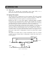
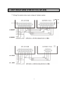
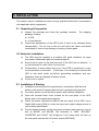
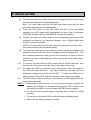
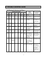
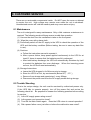
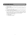
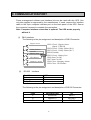
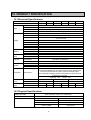
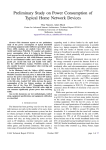
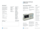
INDUSTRIAL GRADE ON-LINE UPS
SP SERIES
5KVA~ 20KVA
USER’S MANUAL
CONTENTS
Contents
Page
1. SAFETY INSTRUCTION…. ......................................................... P. 2
2. INTRODUCTION…. ..................................................................... P. 4
3. LCD PANEL DISCRIPTION ......................................................... P. 5
4. UNIT REAR VIEW........................................................................ P. 7
5. INSTALLATION.......................................................................... P. 10
6. OPERATION .............................................................................. P. 12
7. TROUBLE SHOOTING GUIDE.................................................. P. 14
8. CUSTOMER SERVICE .............................................................. P. 15
9. COMMUNICATION PORT ......................................................... P. 17
10. PRODUCT SPECIFICATION ................................................... P. 18
♣♣
Item
A.
B.
C.
D.
E.
F.
G.
H.
TESTING INSTRUMENT
♣♣
Description
Brand
4 Channel Oscilloscope
Tektronix
Power Quality Analyzer
Fluke
Digital Multimeter
Fluke
2 Channel Memory Oscilloscope
HAMEG
DC Current Meter 0-30A
YOKOGAWA
Distortion Meter (3~100KW)
GoodWill
AC Power Source 300~500VAC
Dummy Load
1
Model No.
TDS2014
43B
87IV
HM205-3
Y-30
201G
1. SAFETY INSTRUCTION
1.1 Transport
Please transport the UPS system only in the original packaging (to protect
against shock and impact).
1.2 Set-up
Condensation may occur if the UPS system is moved directly from a cold to
a warm environment. The UPS system must be absolutely dry before being
installed. Please allow an acclimatization time of at least two hours.
Do not install the UPS system near water or in damp environments.
Do not install the UPS system where it would be exposed to direct sunlight
or near heat.
Do not block off ventilation openings in the UPS system’s housing.
1.3 Installation
Do not connect appliances or items of equipment which would overload the
UPS system (e.g. Laser printers) to the UPS outlet socket
Place cables in such a way that no one can step on or trip over them.
Do not connect domestic appliances such as hair dryers to UPS output
sockets.
1.4 Operation
Do not disconnect the mains cable on the UPS system or the building wiring
socket outlet (shockproof socket outlet) during operations since this would
cancel the protective earthing of the UPS system and of all connected
loads.
The UPS system features its own, internal current source (batteries). The
UPS output sockets or output terminals block may be electrically lived even
if the UPS system is not connected to the building wiring socket outlet.
Ensure that no fluids or other foreign objects can enter the UPS system.
The UPS operates with hazardous voltages. Only qualified maintenance
personnel may carry out repairs
2
1. SAFETY INSTRUCTION
1.5 Maintenance, servicing and faults
The UPS system operates with hazardous voltages. Only qualified
maintenance personnel may carry out repairs.
Caution - risk of electric shock. Even after the unit is disconnected from the
mains power supply (building wiring socket outlet), components inside the
UPS system are still connected to the battery and are still electrically live
and dangerous.
Before carrying out any kind of servicing and/or maintenance, disconnect
the batteries and verify that no current is present and no hazardous voltage
exist in the terminals of high capability capacitor such as BUS-capacitors.
Only persons are adequately familiar with batteries and with the required
precautionary measures may replace batteries and supervise operations.
Unauthorised persons must be kept well away from the batteries.
Caution - risk of electric shock. The battery circuit is not isolated from the
input voltage. Hazardous voltages may occur between the battery terminals
and the ground. Before touching, please verify that no voltage is present!
Batteries may cause electric shock and have a high short-circuit current.
Please take the precautionary measures specified below and any other
measures necessary when working with batteries:
- remove wristwatches, rings and other metal objects
- use only tools with insulated grips and handles.
When changing batteries, install the same number and same type of
batteries.
Do not attempt to dispose of batteries by burning them. This could cause
battery explosion.
Do not open or destroy batteries. Escaping electrolyte can cause injury to
the skin and eyes. It may be toxic.
Please replace the fuse only by a fuse of the same type and of the same
amperage in order to avoid fire hazards.
Do not dismantle the UPS system.
3
2. INTRODUCTION
2.1 Thank you
Thank you for selecting this uninterruptible power supply (UPS). It is a
state-of-the-art electronic UPS that uses the latest technology.
2.2 System Description
The SP-series UPS is advanced true on-line sinewave UPS which provided
reliable regulated, transient-free AC power to sensitive equipment, ranging from
computers & telecommunication systems to computerized instrument.
Because the UPS is a true on-line system, conditioned power is provided
continuously to the connected device. Unlike the other standby UPS, the UPS is
constantly regulating, filtering the output power. When incoming power is blackout,
the UPS protects the computers instantaneously without any transfer time.
The SP-series UPS has high nonlinear load current capability (i.e. Crest Ratio 3:1)
and this is suitable for powering special load such as switching power supplies.
The bypass function provides bypass power as its standby source. During an
overload condition, the system will automatically transfer to the bypass line (if a
good power exists) within 4 milliseconds to ensure the critical load in normal
operation.
The system can transfer back to inverter automatically (when the overload
condition has been cleared) within 4 milliseconds to ensure the critical load in
normal operation.
MAINTENANCE SWITCH
(Option)
BYPASS
AC OUTPUT
INPUT
Inverter
MCCB1
Charger
External
Battery
Battery
MCCB2
(Optional) External MCCB
Figure 1-1 System Diagram
4
3.2.PANEL DESCRIPTIONS
1. LCD STATUS DISPLAY: UPS monitor its function by itself; such monitoring
messages are displayed in the MULTIPLE DISPLAY.
2. LINE / AC INPUT (Green): The Indicator is ON when the incoming utility power is
available.
3. BYPASS (Amber): The indicator is ON when the UPS output power is supplied
from the incoming power source.
4. LOAD (Red): When the load is over 100W, the indicator would illuminate.
When it reaches over 100% load, UPS would emit an audible alarm sound
continuously for 20seconds.
5. INVERTER FAULT (Red): The indicator is ON when UPS is in faulty condition
and would emit continuous audible alarm sound.
Note: When the unit is at fault condition, please refer to the paragraph 4. Table
and figures.
6. BATTERY (Red): The indicator is ON under these situations:
a) When AC main power fail,
b) AC in under/over voltage
c) Battery discharge reach to a low level, and automatically UPS would emit a
quick alarm reminding that battery has a few energy can be used.
7. INVERTER (Green): The indicator is ON when the UPS Inverter is operating
properly.
5
3.2.PANEL DESCRIPTIONS
8. ALARM RESET : Press it to stop buzzer alarm.
9. POWER ON-Push Button: Press it to start the UPS.
10. POWER OFF-Push Button: Press it to shut down the UPS. If the AC mains
exist, the unit will transfer itself to BYPASS output.
11. MENU/AUTO-Push Button: When press once at a time, it will display the
following sequence of messages:
a) Input Voltage / Frequency
b) Output Voltage / Frequency
c) Current / Percent of Load
d) Battery Voltage / UPS Operating Temperature
When presses for 3 seconds, it will display above messages in an
automatic cycle.
6
4. UNIT REAR VIEW (FOR SP-50~SP-80)
1.
2.
3.
Communication Port (DB9 / RS232)
Ventilation Fan
Output Sockets
4.
5.
Output Fuse
MCCB: To control the AC Input and Battery voltage.
switched on to provide the UPS power.
7
The MCCB should be
4. UNIT REAR VIEW (FOR SP-100~SP-200)
BATTERY PACK
UPS SYSTEM
1. Communication Port (DB9 / RS232): UPS signal passes through DB9
enabling messages to be displayed into computer monitor.
2. Ventilation Fan
3. Bypass / No Fuse Breaker (MCCB2): Switch on when output power is supplied
from bypass.
4. Inverter / No Fuse Breaker (MCCB1): Control the battery bus and rectifier
voltage from AC Power input.
5. Terminal Block: To connect Input / Output connecting wires of power source
and battery pack.
6. Battery / No Fuse Breaker at Battery Back
a) Switch ON to generate battery power into UPS.
b) Switch OFF ceasing the flow of battery power.
7. Terminal Block: Wires schematic diagram connecting battery pack and UPS.
8
4. UNIT REAR VIEW (FOR SP-100~SP-200)
*** Wiring Connection when input voltage is 3 phase system
9
5. INSTALLATION
The system may be installed and wired only by qualified electricians in accordance
with applicable safety regulations!
5.1 Unpacking & Inspection
(1)
Unpack the package and check the package contents.
The shipping
(2)
package contains:
A UPS
A User Manual
Inspect the appearance of the UPS to see if there is any damage during
transportation. Do not turn on the unit and notify the carrier and dealer
immediately if there is any damage or lacking of some parts.
5.2 Notes for Installation
(1)
(2)
The UPS must be installed in a location with good ventilation, far away
from water, inflammable gas and corrosive agents.
Ensure the air vents on the front and rear of the UPS are not blocked. It
is recommended to retain 10cm from the wall.
(3)
Condensation to water drops may occur if the UPS is unpacked in a very
low temperature environment. In this case, it is necessary to wait until the
UPS is fully dried inside out before proceeding installation and use.
Otherwise, there are hazards of electric shock.
(4)
Put the unit in a plain.
5.3 Installation & Starting
(1)
(2)
(3)
Installation and wiring must be performed in accordance with the local
electric code and the following instructions by professional personnel.
For safety, please cut off the mains power switch before installation.
Open the terminal block cover located on the rear panel of the UPS,
please refer to the appearance diagram.
(4)
Check the power requirement label at the rear panel of the UPS, use a
Digital Multi-meter (DVM) to check the input and output voltage accord to
your ordered specification.
(5)
Find the battery breaker on the rear panel of battery bank and turn it on as
well as MCCB1 and MCCB2. The indicators of “LINE”, “BYPASS”,
“INVERTER” and “FAULT” will all light on. If AC mains exist, the fans on
the rear panel operate with AC power outputs (BYPASS).
10
5. INSTALLATION
(6)
Connect the input and output wires to the corresponding input and output
terminals according to the following diagram.
Note:You must make sure that the input and output wires and the input
and output terminals are connected tightly.
(7) Press the “ON” button on the front panel, the fan on the front panel
operates, and UPS detect itself automatically at once. After 25 seconds,
“BYPASS” extinguishes and “INVERTER” remains illuminating.
(8)
Connect the input and output wires to the corresponding input and output
terminals according to the following diagram. Use a Digital Multi-meter
(DVM) to check the voltage.
NOTE: You must make sure that the input and output wires and the input
and output terminals are connected tightly.
(9)
The protective earth ground wire refers to the wire connection between the
equipment which consumes electric equipment and the ground wire. The
wire diameter protective earth ground wire should be at least as above
mentioned for each model and green wire or green wire with yellow ribbon
(10)
(11)
(12)
wire is used.
To connect the load with the UPS, please turn off all the loads first, then
perform the connection and finally turn on the loads one by one.
No matter the UPS is connected to the utility power or not, the output of
the UPS may have electricity. The parts inside the unit may still have
hazardous voltage after turning off the UPS. To make the UPS have no
output, power off the UPS, and then disconnect the utility power supply.
The UPS now is ready for working, connecting the critical equipment to the
output terminal blocks.
NOTE : a. Keep power continuously for 12 hours at the first start to ensure the
battery fully charged. It is recommended to press “OFF” button on the
front panel but open the circuit breaker MCCB1 during charging.
b Do not touch the external battery terminals, there is high DC voltage
remains.
c Do not short-circuit wires at the external battery terminals block.
d Make sure the battery polarity is correct.
11
6. OPERATION
6.1 Check Prior to Start UP
(1) Ensure the UPS is in a suitable positioning.
(2) Check input cord is secured.
(3) Make sure the load is disconnected or in the “OFF” position.
(4) Check if input voltage meets the UPS rating required.
6.2 Start-up Procedure
(1) Turn on the circuit breaker.
(2) Push the “ON” switch on the front panel. (Blue color switch)
(3) Turn on the power breaker of your critical equipment.
6.3 Turn OFF Procedure
(1) Turn off all the power breakers on your critical equipment which are
connected to the UPS.
(2) Press the “ON/OFF” buttons on the front panel.
(3) Turn off the NFB (MCCB1 & MCCB2) on the rear panel.
NOTE : a. The NFB can be kept in “ON” position to charge the batteries when
the line input is normal.
b. For daily TURN ON / TURN OFF operation, it is recommended to
keep the breaker turned on to ensure proper battery operation.
WARNING : If the breaker is in “ON” position, the line power will be supplied to
outlets. Do not insert objects other than equipment power cords
into the outlets.
6.4 Working
(1) When utility power is interrupted, the UPS converts the built-in battery
source to protect your critical load from loss of data or damage.
(2) Battery back-up time is 10 - 15 minutes for full load and can be extended
by removing non-critical loads.
(3) After utility power black-out, the audible alarm will sound every 4 seconds
to show that output is backed-up by battery source.
(4) When audible alarm speeds up and sounds every 1 second, data should
be saved and all loads should be shut down at once.
12
6. OPERATION
NOTE : a.
Follow the application software in use as well as the computer
manufacturer’s instructions for saving data and turning off the
computer.
b. After a blackout, keep the breaker (MCCB1) “ON” for at least 10
hours to ensure the batteries are fully recharged.
13
7. TROUBLE SHOOTING GUIDE
The Meaning of Indicators and Alarm
Indicators and Alarm
Line
INV Battery Bypass Load
Input
ON ON
ON
OFF
---OFF ON Flashing OFF
----
Recommended
Condition
Solution
Fault
Buzzer
OFF
OFF
NO Normal
Every Normal, AC mains
4 sec. failure. UPS is
charging batteries.
NO UPS works on
BYPASS
ON
OFF
ON
ON
----
ON
---
---
ON or
Flashing
----
ON
OFF
ON Flashing
OFF
ON
OFF
---
ON
ON
OFF
ON
OFF
ON
---
ON
---
----
OFF
---
ON
ON
or
Flashing
OFF
ON
ON
ON
---
ON
---
----
OFF
OFF
Status
Close your
software and files
in use.
Press “ON” the
Main Switch on
the front panel
first
Conti- UPS is at overload Remove
nuous condition
nonessential load
equipment.
Every Normal, battery
Close your files
1 sec. will discharge
and software in
completely.
use.
Conti- The output circuit Remove the short
nuous is shorted.
circuit and start
the UPS again.
Conti- UPS works on
Warming only
nuous INV. or BYPASS, without affecting
while the input
UPS operation.
voltage is more
than 270V
Conti- UPS interior gets UPS will transfer
nuous too hot as it has to BYPASS mode.
been worked on
INV. for a period
of time.
Conti- UPS works on
Call for service, if
nuous INV. or BYPASS. UPS works on
INV.. Whereas,
the UPS work on
BY-PASS is
because the AC
voltage is too
high.
14
8. CUSTOMER SERVICE
There are no serviceable components inside. Do NOT open the cover or attempt
to service the unit. High voltage may remain even when the unit is shutdown.
Unauthorized service will void the warranty and may cause serious injury.
8.1 Maintenance
The unit is designed for easy maintenance. Only a little customer maintenance is
required. The following works will keep ensure trouble-free operation.
(1) Vacuum the dust from the ventilation in-take on the front panel.
(2) Wipe the cover with a damp cloth.
(3) Periodically switch off the AC supply to the UPS to check the operation of the
UPS and the battery condition (Before testing, be sure to save any data files
in use).
(4) Cautions:
a. Follow the instruction manual to operate it.
b. After a power failure, keep power applied continuously to the UPS for at
least 12 hours to ensure that the batteries are fully recharged.
c. After total battery discharge, the UPS will automatically shutdown by itself
to protect the batteries from over discharge. When the incoming power
recover, the UPS will reset automatically.
(4) Storage Instructions:
a. Leave the UPS plugged in for 24hours prior to storage.
b. Store the UPS in a cool, dry environment (Below 80℉ / 27℃).
c. Remove from storage and repeat step 1 every 90days.
d. Disconnect the power cord from the AC supply socket during storage.
8.2 Trouble Shooting
Due to the unique design, the unit must be serviced by authorized person only.
If the UPS fails to operate properly, turn off the power first and review the
following check list. Be prepared to answer the following question before calling
for service.
(1) Is the AC supply power rating correct?
(2) Is the power cord connection loose?
(3) Turn ON the Main Switch again. Does the UPS return to normal operation?
(4) Did a power failure occur just after or before the malfunction was noted?
15
8. CUSTOMER SERVICE
(5) What is the status of the indicator at the time of the malfunction? And on
restarting the UPS?
(6) Where any changes made to the UPS or the critical device attached to the
unit?
(7) Did overload condition happen? If so, remove non-critical loads from the
unit and go through the restart procedure.
(8) In addition, check the fuse or breaker on the rear panel. Is the fuse busted or
the circuit protector tripped? If the UPS fails to operate normally after
carrying out these checks, contact our local service representative. Please
note down the following information before you call for service:
a. Model number & serial number.
b. Date of problem
c.
Full descriptions of problem
16
9. COMMUNICATION PORT
Power management software and interface kits can be used with this UPS. Use
only kits supplied or approved by the manufacturer. If used, connect the interface
cable to the 9-pin computer interface port on the back panel of the UPS. Secure
the connector’s screws to complete the connection.
Note: Computer interface connection is optional. The UPS works properly
without it.
(1) DB-9 Interface
The following is the pin assignment and description of DB-9 Connector:
Bypass Active
Utility Failure
Ground
Battery Low
UPS Failure
Summary Alarm
(2)
RS-232
PIN1 (Close) : Bypass Active
(Open) : UPS ON
PIN2 (Close) : Utility Failure (N.O.)
PIN3 (Close) : Utility Failure (N.C.)
PIN4 (Ground)
PIN5 (Close) : Battery Low
PIN6 Auto Cut Off
PIN7 Auto Cut Off
PIN8 Close : Summary Alarm
PIN9 Close : UPS Failure
Interface
Baud Rate:
Data:
Stop:
Parity Bit:
2400bp
8bit
1bit
None
The following is the pin assignment and description of RS-232 Connector:
PIN#
DESCRIPTION
I/O
6
RS232 Rx
INPUT
9
RS232 Tx
OUTPUT
7
Ground
INPUT
17
10. PRODUCT SPECIFICATION
10.1 Electrical Specifications
Model
Capacity (KVA)
Voltage
Frequency
Input
SP-50
5
SP-60
SP-80
SP-100
SP-150
6
8
10
15
180V~280V (230V) / 90V ~149V (115V)
50 or 60Hz ± 5%
1Ø 2W+G / 3Ø 3W+G / 3Ø 4W+G (as client demand)
0.8 to 1 lagging
Phase
Power Factor
Voltage
115V or 230V ± 2%
1Ø 2W+G (as client demand)
Phase
Voltage Regulation
Output
Battery
Transfer
Time
Indicator
Audible
Frequency
Waveform Distortion
Crest Factor
Overload Capacity
Efficiency AC-AC
Type
Back up Time
Recharge Time
Bypass to UPS
UPS to Bypass
LCD Display
LED Display
Mains Fail
Battery low
UPS fault
Protection
Short Circuit
W*H*D /
(mm)
UPS
Net Weight
(kgs)
SP-200
20
± 1% at liner load
50 or 60Hz ± 0.5Hz
Pure sinewave less than 3% at full load.
3:1
100%-124% continuous, 125% -150% for 25 seconds.
>80% at battery fully charge
rechargeable, sealed maintenance-free
10 min. at full load and 25 min. at half load.
4-8 hours 90% after fully discharge.
No break
No break.
Input/Output & Battery Voltage, Frequency, Output Load,
Operation Temperature
Mimic display
Sounds every 4 seconds after line fails.
Sounds every second when approaches battery low level.
Continuous alarm.
When a short circuit occurs, the UPS will not transfer to Bypass
but emit a sustained tone. Once the short circuit is removed, the
tone stops and the whole system operates normally again.
The UPS stops supplying power if the period of a short circuit is
longer than 3 seconds.
Lightning : Yes.
Surge : Yes.
270*800*660
310*900*660
360*740*870
Battery Bank
-----
-----
360*740*870
UPS
130
160
190
320
190
230
Battery Bank
-----
-----
-----
-----
200
200
10.2 Physical Specifications
Relative Humidity :
Audible Noise :
Operating Altitude :
90% maximum at 25°C non-condensing.
55dB, ANSI A scale at 3 feet.
(Above sea level)
Operating Temperature
0-4,800ft
40°C (104°F)
4,800-7,000ft
38°C (100.4°F)
7,000-10,000ft
35°C (95°F)
18