1
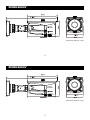
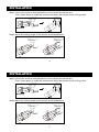
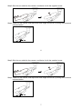
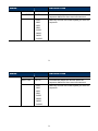
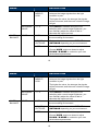
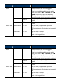
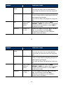
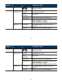
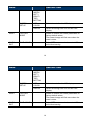
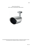
697Z IR Bullet Camera User Manual The product image shown above may differ from the actual product. Please use this camera with a DVR which supports HD video recording. Please read the instructions thoroughly before using the product. d205x_V1.1 697Z IR Bullet Camera User Manual The product image shown above may differ from the actual product. Please use this camera with a DVR which supports HD video recording. Please read the instructions thoroughly before using the product. d205x_V1.1 IMPORTANT SAFEGUARD CAUTION RISK OF ELECTRIC SHOCK CAUTION: To reduce the risk of electric shock, do not expose this apparatus to rain or moisture. Only operate this apparatus from the type of power source indicated on the label. The company shall not be liable for any damages arising out of any improper use, even if we have been advised of the possibility of such damages. The lightning flash with arrowhead symbol, within an equilateral triangle, is intended to alert the user to the presence of uninsulated “dangerous voltage” within the product’s enclosure that may be of sufficient magnitude to constitute a risk of electric shock to persons. This exclamation point within an equilateral triangle is intended to alert the user to the presence of important operating and maintenance (servicing) instructions in the literature accompanying the appliance. All lead-free products offered by the company comply with the requirements of the European law on the Restriction of Hazardous Substances (RoHS) directive, which means our manufacture processes and products are strictly “lead-free” and without the hazardous substances cited in the directive. The crossed-out wheeled bin mark symbolizes that within the European Union the product must be collected separately at the product end-of-life. This applies to your product and any peripherals marked with this symbol. Do not dispose of these products as unsorted municipal waste. Contact your local dealer for procedures for recycling this equipment. CE Mark This apparatus is manufactured to comply with the radio interference. The company does not warrant that this manual will be uninterrupted or error-free. We reserve the right to revise or remove any content in this manual at any time. IMPORTANT SAFEGUARD CAUTION RISK OF ELECTRIC SHOCK CAUTION: To reduce the risk of electric shock, do not expose this apparatus to rain or moisture. Only operate this apparatus from the type of power source indicated on the label. The company shall not be liable for any damages arising out of any improper use, even if we have been advised of the possibility of such damages. The lightning flash with arrowhead symbol, within an equilateral triangle, is intended to alert the user to the presence of uninsulated “dangerous voltage” within the product’s enclosure that may be of sufficient magnitude to constitute a risk of electric shock to persons. This exclamation point within an equilateral triangle is intended to alert the user to the presence of important operating and maintenance (servicing) instructions in the literature accompanying the appliance. All lead-free products offered by the company comply with the requirements of the European law on the Restriction of Hazardous Substances (RoHS) directive, which means our manufacture processes and products are strictly “lead-free” and without the hazardous substances cited in the directive. The crossed-out wheeled bin mark symbolizes that within the European Union the product must be collected separately at the product end-of-life. This applies to your product and any peripherals marked with this symbol. Do not dispose of these products as unsorted municipal waste. Contact your local dealer for procedures for recycling this equipment. CE Mark This apparatus is manufactured to comply with the radio interference. The company does not warrant that this manual will be uninterrupted or error-free. We reserve the right to revise or remove any content in this manual at any time. TABLE OF CONTENTS FEATURES PACKAGE CONTENT DIMENSIONS* SPECIFICATIONS* INSTALLATION CONNECTION CAMERA PARAMETERS FAQ 1 1 2 3 4 6 7 15 TABLE OF CONTENTS FEATURES PACKAGE CONTENT DIMENSIONS* SPECIFICATIONS* INSTALLATION CONNECTION CAMERA PARAMETERS FAQ 1 1 2 3 4 6 7 15 FEATURES 1. 1/ 2.9” CMOS Sensor with 1080P video output 2. Low light sensitivity of 0.1 Lux / F1.4(Wide)~F2.8(Tele), 0 Lux (IR LED ON) 3. IR effective distance up to 25 meters for day and night surveillance 4. IP66 for weather-proof application 5. Camera parameters adjustable when used with HD CCTV DVR PACKAGE CONTENT IR camera * 1 User manual * 1 Accessory * 1 Sun shield * 1 Installation sticker * 1 1 FEATURES 1. 1/ 2.9” CMOS Sensor with 1080P video output 2. Low light sensitivity of 0.1 Lux / F1.4(Wide)~F2.8(Tele), 0 Lux (IR LED ON) 3. IR effective distance up to 25 meters for day and night surveillance 4. IP66 for weather-proof application 5. Camera parameters adjustable when used with HD CCTV DVR PACKAGE CONTENT IR camera * 1 User manual * 1 Accessory * 1 Sun shield * 1 1 Installation sticker * 1 DIMENSIONS* *Dimensional Tolerance: ± 5mm 2 DIMENSIONS* *Dimensional Tolerance: ± 5mm 2 SPECIFICATIONS* Pick-up Element Number of Pixels Video Frame Rate Min. Illumination S/N Ratio Shutter Speed Lens Lens Angle IR LED IR Effective Distance IR Shift Day & Night Mode IRIS Mode White Balance AGC Sharpness IP Rating Operating Temperature Power Source (±10%) Current consumption (±10%) 1/ 2.9” CMOS image sensor 1936(H) × 1096(V) 1080P@30fps / 1080P@25fps 0.1 Lux / F1.4(Wide)~F2.8(Tele), 0 Lux (IR LED ON) More than 48dB (AGC OFF) 1/30 (1/25) sec ~ 1/33750 (1/28125) sec f2.8 ~ 12mm / F1.4 ~ F2.8 Wide: 103° (Horizontal) / 54° (Vertical) / 122° (Diagonal) Tele: 31° (Horizontal) / 17° (Vertical) / 36° (Diagonal) 36 units Up to 25 meters YES YES AES AUTO / INDOOR / OUTDOOR / USER High / Middle / Low / Off Adjustable IP66 -25℃ ~ 50℃ DC12V / 1A 210mA (IR OFF); 520mA (IR ON) * The specifications are subject to change without notice. 3 SPECIFICATIONS* Pick-up Element Number of Pixels Video Frame Rate Min. Illumination S/N Ratio Shutter Speed Lens Lens Angle IR LED IR Effective Distance IR Shift Day & Night Mode IRIS Mode White Balance AGC Sharpness IP Rating Operating Temperature Power Source (±10%) Current consumption (±10%) 1/ 2.9” CMOS image sensor 1936(H) × 1096(V) 1080P@30fps / 1080P@25fps 0.1 Lux / F1.4(Wide)~F2.8(Tele), 0 Lux (IR LED ON) More than 48dB (AGC OFF) 1/30 (1/25) sec ~ 1/33750 (1/28125) sec f2.8 ~ 12mm / F1.4 ~ F2.8 Wide: 103° (Horizontal) / 54° (Vertical) / 122° (Diagonal) Tele: 31° (Horizontal) / 17° (Vertical) / 36° (Diagonal) 36 units Up to 25 meters YES YES AES AUTO / INDOOR / OUTDOOR / USER High / Middle / Low / Off Adjustable IP66 -25℃ ~ 50℃ DC12V / 1A 210mA (IR OFF); 520mA (IR ON) * The specifications are subject to change without notice. 3 INSTALLATION Step1: Loosen the screw as indicated below to move down the camera lens. Then, locate where to install this camera, and fasten the camera to the ceiling or wall. Step2: Adjust the viewing angle of the camera as indicated below. 4 INSTALLATION Step1: Loosen the screw as indicated below to move down the camera lens. Then, locate where to install this camera, and fasten the camera to the ceiling or wall. Step2: Adjust the viewing angle of the camera as indicated below. 5 Step3: Slide the sun shield to the camera, and fasten it with the supplied screw. Step4: Power on the camera, and adjust the focal length and focus by turning the screws as indicated below. 6 Step3: Slide the sun shield to the camera, and fasten it with the supplied screw. Step4: Power on the camera, and adjust the focal length and focus by turning the screws as indicated below. 7 CONNECTION 1. DC12V Input Terminal Connect the power terminal of the camera to a DC 12V regulated power supply. Note: Please use the correct power adaptor, DC12V (regulated), to operate this unit. The power tolerance of this unit is DC12V ± 10%. Over maximum DC 12V power input will damage this unit. 1. Video Output Connector (VIDEO OUT) Connect the camera video output to the video input of a DVR with 75Ω coaxial cable. Note: To ensure the camera has sufficient protection against moisture, an extra waterproof measure, such as by using an insulating tape, must be used to cover the power and video connectors after connection. 8 CONNECTION 1. DC12V Input Terminal Connect the power terminal of the camera to a DC 12V regulated power supply. Note: Please use the correct power adaptor, DC12V (regulated), to operate this unit. The power tolerance of this unit is DC12V ± 10%. Over maximum DC 12V power input will damage this unit. 1. Video Output Connector (VIDEO OUT) Connect the camera video output to the video input of a DVR with 75Ω coaxial cable. Note: To ensure the camera has sufficient protection against moisture, an extra waterproof measure, such as by using an insulating tape, must be used to cover the power and video connectors after connection. 6 CAMERA PARAMETERS This camera series has its own configuration menu, and either of the two methods below is available to access the menu based on the camera model you have. Note: The methods below are available only when the camera is used with our brand’s HD CCTV DVR. Method 1 On the DVR live view, click the channel which connects this camera to display in the full screen mode, and select . Click “” to enter the menu of camera parameters. Method 2 On the DVR live view, right click to show the DVR main menu, and select ADVANCED CONFIG DCCS. Then, select the channel which connects this camera, and click SETUP to enter the menu of camera parameters. 7 CAMERA PARAMETERS This camera series has its own configuration menu, and either of the two methods below is available to access the menu based on the camera model you have. Note: The methods below are available only when the camera is used with our brand’s HD CCTV DVR. Method 1 On the DVR live view, click the channel which connects this camera to display in the full screen mode, and select . Click “” to enter the menu of camera parameters. Method 2 On the DVR live view, right click to show the DVR main menu, and select ADVANCED CONFIG DCCS. Then, select the channel which connects this camera, and click SETUP to enter the menu of camera parameters. 7 ADVANCED CONFIG CAMERA DETECTION ALERT NETWORK DISPLAY RECORD DEVICES DCCS NOTIFY CH1 CH2 MENU CH3 CH4 SETUP DEVICE XXXXX CONNECTION OK When the camera menu is entered, you’ll see the keys on the bottom right corner to move between and change those configurations. Move between selections. X Quit the camera parameters mode. Change settings. Call the camera parameters menu or enter the currently-selected item. 8 ADVANCED CONFIG CAMERA DETECTION ALERT NETWORK DISPLAY RECORD DEVICES DCCS NOTIFY CH1 CH2 MENU CH3 CH4 SETUP DEVICE XXXXX CONNECTION OK When the camera menu is entered, you’ll see the keys on the bottom right corner to move between and change those configurations. Move between selections. X Quit the camera parameters mode. Change settings. Call the camera parameters menu or enter the currently-selected item. 8 MENU DESCRIPTION EXPOSURE LENS TYPE SHUTTER FIX No function. AUTO Automatically adjust the shutter speed for exposure based on the current environment. 1/100 1/200 1/250 1/500 1/1000 1/2000 1/4000 1/10000 Manually choose the shutter speed you need for exposure. 9 MENU DESCRIPTION EXPOSURE LENS TYPE SHUTTER FIX No function. AUTO Automatically adjust the shutter speed for exposure based on the current environment. 1/100 1/200 1/250 1/500 1/1000 1/2000 1/4000 1/10000 Manually choose the shutter speed you need for exposure. 9 MENU DESCRIPTION EXPOSURE AGC WHITE BALANCE OFF / LOW / MIDDLE / HIGH Set the level of Auto Gain Control to detect and enhance the image signals when the light condition is poor. The higher the value, the stronger the signals will be enhanced, and the more noise the image will get. EXPOSURE VALUE 1 ~ 17 When AUTO is selected and you’re not satisfying with current image brightness, you can manually adjust the value to add or decrease the exposure level. MODE AUTO Automatically adjust the white balance based on the surrounding environment. INDOOR / OUTDOOR Fix the white balance mode to INDOOR / OUTDOOR depending on your environment. USER Manually adjust the white balance parameters. Choose USER, and move down to adjust R-GAIN / B-MODE to customize your own white balance parameters. 10 MENU DESCRIPTION EXPOSURE AGC WHITE BALANCE OFF / LOW / MIDDLE / HIGH Set the level of Auto Gain Control to detect and enhance the image signals when the light condition is poor. The higher the value, the stronger the signals will be enhanced, and the more noise the image will get. EXPOSURE VALUE 1 ~ 17 When AUTO is selected and you’re not satisfying with current image brightness, you can manually adjust the value to add or decrease the exposure level. MODE AUTO Automatically adjust the white balance based on the surrounding environment. INDOOR / OUTDOOR Fix the white balance mode to INDOOR / OUTDOOR depending on your environment. USER Manually adjust the white balance parameters. Choose USER, and move down to adjust R-GAIN / B-MODE to customize your own white balance parameters. 10 MENU DAY & NIGHT DESCRIPTION MODE IMAGE SET BRIGHTNESS CONTRAST EXT Use the external light sensor we added in the camera to detect the surrounding light condition and switch to color or B/W mode. If you’re not satisfying with the mode switch time, move down to D N LEVEL / N D LEVEL to manually adjust the sensitivity. The higher the value is, the higher the sensitivity is and quicker the mode is switched. COLOR Always keep the day and night mode to day mode. B/W Always keep the day and night mode to night mode. 1 ~ 256 Set the level of brightness to adjust the brightness of the image. The more the value, the brighter the image will be. 1 ~ 256 Set the level of contrast. The more the value, the more the contrast level of the image will be. 11 MENU DAY & NIGHT DESCRIPTION MODE IMAGE SET BRIGHTNESS CONTRAST EXT Use the external light sensor we added in the camera to detect the surrounding light condition and switch to color or B/W mode. If you’re not satisfying with the mode switch time, move down to D N LEVEL / N D LEVEL to manually adjust the sensitivity. The higher the value is, the higher the sensitivity is and quicker the mode is switched. COLOR Always keep the day and night mode to day mode. B/W Always keep the day and night mode to night mode. 1 ~ 256 Set the level of brightness to adjust the brightness of the image. The more the value, the brighter the image will be. 1 ~ 256 Set the level of contrast. The more the value, the more the contrast level of the image will be. 11 MENU DESCRIPTION IMAGE SET COLOR GAIN 1 ~ 256 Set the level of color saturation. The more the value, the more saturated the color will be, but the more noise the image will get. SHARPNESS 1 ~ 256 Set the level of sharpness to enhance the clarity of image detail by adjusting the aperture and sharpening the edges. The more the value, the sharper the image will be. NR OFF / LOW / MIDDLE HIGH Set the noise reduction mode to LOW / MIDDLE / HIGH to suppress the noise based on the current environment, or select OFF to disable this function. MIRROR NONE / H / V / HV Rotate the images horizontally (H) or vertically (V), or horizontally & vertically (HV) simultaneously based on your installation situation when necessary. 12 MENU DESCRIPTION IMAGE SET COLOR GAIN 1 ~ 256 Set the level of color saturation. The more the value, the more saturated the color will be, but the more noise the image will get. SHARPNESS 1 ~ 256 Set the level of sharpness to enhance the clarity of image detail by adjusting the aperture and sharpening the edges. The more the value, the sharper the image will be. NR OFF / LOW / MIDDLE HIGH Set the noise reduction mode to LOW / MIDDLE / HIGH to suppress the noise based on the current environment, or select OFF to disable this function. MIRROR NONE / H / V / HV Turn the images horizontally (H) or vertically (V), or horizontally & vertically (HV) simultaneously based on your installation situation when necessary. 12 MENU DESCRIPTION IMAGE SET LANGUAGE ENGLISH / 中文(簡) Select the language of the menu: English / Simplified Chinese. FUNC. SET MOTION DETECTON* SCREEN ALARM Select ON to enable motion detection or OFF to disable this function. PAD OUTPUT No function. SECTION Select the area for motion detection. SENSITIVITY Select the sensitivity for motion detection from LOW, MIDDLE and HIGH. You’ll see a default masking area on the screen. MASKING Select ON / OFF to enable / disable this function. COLOR Select a color to show area masking. PRIVACY * The function here is for this camera only, and the detection log will be not noted in the DVR. 13 MENU DESCRIPTION IMAGE SET LANGUAGE ENGLISH / 中文(簡) Select the language of the menu: English / Simplified Chinese. FUNC. SET MOTION DETECTON* SCREEN ALARM Select ON to enable motion detection or OFF to disable this function. PAD OUTPUT No function. SECTION Select the area for motion detection. SENSITIVITY Select the sensitivity for motion detection from LOW, MIDDLE and HIGH. You’ll see a default masking area on the screen. MASKING Select ON / OFF to enable / disable this function. COLOR Select a color to show area masking. PRIVACY * The function here is for this camera only, and the detection log will be not noted in the DVR. 13 MENU FUNC. SET DESCRIPTION PRIVACY HEIGHT / WIDTH / LEFT / RIGHT / TOP / BOTTOM Set the area to mask. SYSTEM SETUP OSD COLOR Select the color for this OSD display. OSD BG Select the background color for this OSD display. RESET FACTORY MODE Enable to restore the camera parameters to factory default values. The camera image will flash once when the reset is done. SAVE & EXIT SAVE & EXIT Select YES to save and exit, or select NO to exit without saving. 14 MENU FUNC. SET DESCRIPTION PRIVACY HEIGHT / WIDTH / LEFT / RIGHT / TOP / BOTTOM Set the area to mask. SYSTEM SETUP OSD COLOR Select the color for this OSD display. OSD BG Select the background color for this OSD display. RESET FACTORY MODE Enable to restore the camera parameters to factory default values. The camera image will flash once when the reset is done. SAVE & EXIT SAVE & EXIT Select YES to save and exit, or select NO to exit without saving. 14 FAQ Q: The image quality at night is too dark. What can I do to improve it? A: Please go to the camera’s parameter setting page as described in the section of “CAMERA PARAMETERS”, and select EXPOSURE -> AGC to change the value to MIDDLE, and check again. 15 FAQ Q: The image quality at night is too dark. What can I do to improve it? A: Please go to the camera’s parameter setting page as described in the section of “CAMERA PARAMETERS”, and select EXPOSURE -> AGC to change the value to MIDDLE, and check again. 15