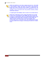
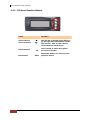
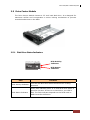
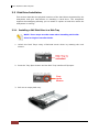
1
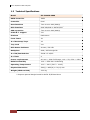
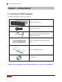
SAS to SAS/SATA II JBOD Subsystem User Manual Revision 1.0 SAS to SAS/SATA II JBOD Subsystem Table of Contents Chapter 1 Introduction .................................................................................................... 4 1.1 Features .............................................................................................................................................................................. 5 1.2 Technical Specifications ............................................................................................................................................... 6 1.3 Terminologies .................................................................................................................................................................. 7 Chapter 2 Getting Started .............................................................................................. 8 2.1 Unpacking the JBOD Subsystem ............................................................................................................................. 8 2.2 Identifying Parts of the JBOD Subsystem ............................................................................................................ 9 2.2.1 Front View ................................................................................................................................................................ 9 2.2.2 Rear View ................................................................................................................................................................10 2.2.3 JBOD Controller Module ..................................................................................................................................11 2.2.3.1 2.3 JBOD Controller Panel ..............................................................................................................................11 Power Supply Fan Module (PSFM) .......................................................................................................................13 2.3.1 2.4 PSFM Panel ............................................................................................................................................................13 LCD Display Panel ........................................................................................................................................................15 2.4.1 LCD Panel LED ......................................................................................................................................................15 2.4.2 LCD Panel Function Buttons ...........................................................................................................................16 2.5 Drive Carrier Module ..................................................................................................................................................17 2.5.1 Disk Drive Status Indicators ............................................................................................................................17 2.5.2 Drive Carrier Lock Indicator ............................................................................................................................18 Chapter 3 Installation of JBOD Subsystem ............................................................. 19 3.1 Powering On ..................................................................................................................................................................19 3.2 Disk Drive Installation.................................................................................................................................................20 3.2.1 Installing a SAS Disk Drive in a Disk Tray.................................................................................................20 3.2.2 Installing a SATA Disk Drive (Dual JBOD Controller Mode) in a Disk Tray ................................23 3.3 Connecting the JBOD Subsystem..........................................................................................................................27 3.3.1 Connecting to RAID Subsystem ....................................................................................................................27 Chapter 4 Quick Setup ................................................................................................... 28 4.1 Management Interfaces .............................................................................................................................................28 4.1.1 LCD Control Module (LCM) ............................................................................................................................28 4.2 Connecting JBOD to RAID Controller ..................................................................................................................30 4.3 Upgrading Firmware ...................................................................................................................................................34 Chapter 5 Maintenance ................................................................................................. 35 5.2 Replacing JBOD Subsystem Components..........................................................................................................35 5.2.1 2 Replacing JBOD Controller Module.............................................................................................................35 User Manual SAS to SAS/SATA II JBOD Subsystem 5.2.1.1 5.2.2 Replacing Controller Module with Plate Cover .............................................................................36 Replacing Power Supply Fan Module.........................................................................................................37 5.2.2.1 Replacing Power Supply Fan Module with Plate Cover .............................................................38 User Manual 3 SAS to SAS/SATA II JBOD Subsystem Chapter 1 Introduction The 16 bays EPICa JBOD Subsystem The EPICa EP-3164JD-S6S6 is a 19-inch 3U 16 bays rackmount JBOD unit. It features the latest SAS II (6Gb/s) interface and comes with dual JBOD controllers to support dual-active configuration. It designed to fit in with the environments which needed highly reliable and relentless data growth. The EP-3164JD-S6S6 is also a versatile SAS / SATA Disk Expansion system, ideal for high capacity and scalability storage in IT demands. Based on the 6G SAS technology, the EP-3164JD-S6S6 supports the choice of SAS and SATA drive configurations to deliver the best costperformance index with higher bandwidth. 4 User Manual SAS to SAS/SATA II JBOD Subsystem 1.1 Features 16 hot-swappable drive bays in a rackmount 3U chassis Simultaneously support SAS or SATA disks Each SAS JBOD controller module consist of two 6G mini SAS (4x) port Power Supply and cooling system contained in 1 module for efficient cooling Two 500W redundant hot swappable power supplies Incorporates a cableless design for maximum signal integrity Utilizes industry-standard SCSI Enclosure Services to monitor enclosure and disk environmental conditions Enclosure monitoring S.E.S. support for standard enclosure management System LED indications Fan speed monitoring Power supply monitoring System voltage monitoring System temperature monitoring System alarm User Manual 5 SAS to SAS/SATA II JBOD Subsystem 1.2 Technical Specifications Model EP-3164JD-S6S6 RAID Controller JBOD Controller Dual Host Interface Two 4x mini SAS (6Gb/s) Disk Interface SAS 3Gb/6Gb or SATA II/III * SAS expansion Two 4x mini SAS (6Gb/s) S.M.A.R.T. support Yes Platform Rackmount Form Factor 3U # of Hot Swap Trays 16 Tray Lock Yes Disk Status Indicator Access / Fail LED Backplane SAS / SATA Single BP # of PS/Fan Modules 500W x 2 w/PFC # of Fans 4 Power requirements AC 90V ~ 264V Full Range, 10A ~ 5A, 47Hz ~ 63Hz Relative Humidity 10% ~ 85% Non-condensing Operating Temperature 10°C ~ 40°C (50°F ~ 104°F) Physical Dimension 566(L) x 482(W) x 131(H) mm Weight (Without Disk) 22.5 Kg * Request optional dongle board for SATA II/III hard drive 6 User Manual SAS to SAS/SATA II JBOD Subsystem 1.3 Terminologies The document uses the following terms: Part 1: Common RAID Redundant Array of Independent Disks. There are different RAID levels with different degree of data protection, data availability, and performance to host environment. JBOD The abbreviation of “Just a Bunch Of Disks”. JBOD needs at least one hard drive. SCSI Small Computer Systems Interface. SAS Serial Attached SCSI. S.M.A.R.T. Self-Monitoring Analysis and Reporting Technology. WWN World Wide Name. HBA Host Bus Adapter. Part 2: Dual controller SBB Storage Bridge Bay. The objective of the Storage Bridge Bay Working Group (SBB) is to create a specification that defines mechanical, electrical and low-level enclosure management requirements for an enclosure controller slot that will support a variety of storage controllers from a variety of independent hardware vendors (“IHVs”) and system vendors. Dongle Board SATA Dongle board is for SATA II disk connection to the dual controller backplane. Bridge Board SAS-SATA Bridge board is for SATA II disk connection to the dual JBOD backplane. User Manual 7 SAS to SAS/SATA II JBOD Subsystem Chapter 2 Getting Started 2.1 Unpacking the JBOD Subsystem The shipping package contains the following: JBOD Subsystem Unit Two (2) power cords Two (2) external Mini SAS cables SFF8088 to SFF-8088 One (1) JBOD Controller Module Plate Cover One (1) PSFM Plate Cover User Manual NOTE: If any damage is found, contact the dealer or vendor for assistance. 8 User Manual SAS to SAS/SATA II JBOD Subsystem 2.2 Identifying Parts of the JBOD Subsystem The illustrations below identify the various parts of the expansion chassis. 2.2.1 Front View User Manual 9 SAS to SAS/SATA II JBOD Subsystem 2.2.2 Rear View 10 User Manual SAS to SAS/SATA II JBOD Subsystem 2.2.3 JBOD Controller Module JBOD Controller Module 2.2.3.1 JBOD Controller Panel Part Description SAS In Port Use to connect to RAID subsystem’s SAS Expansion Port. SAS Expansion Port Use to connect to the SAS In Port of another JBOD subsystem. User Manual 11 SAS to SAS/SATA II JBOD Subsystem Indicator Color Description Master/Slave LED Green Indicates the master controller; Off indicates the slave controller. JBOD Status LED Green Indicates controller status normal or in the booting state. Link LED Blue Indicates expander has connected or linked. Access LED Blinking Green Indicates the expander is busy and being accessed. 12 User Manual SAS to SAS/SATA II JBOD Subsystem 2.3 Power Supply Fan Module (PSFM) The RAID subsystem contains two 500W Power Supply / Fan Modules. All the Power Supply / Fan Modules (PSFMs) are inserted into the rear of the chassis. 2.3.1 PSFM Panel The panel of the Power Supply/Fan Module contains: the Power On/Off Switch, the AC Inlet Plug, and a Power On/Fail Indicator showing the Power Status LED, indicating ready or fail. Each fan within a PSFM is powered independently of the power supply within the same PSFM. So if the power supply of a PSFM fails, the fan associated with that PSFM will continue to operate and cool the enclosure. When the power cord connected from main power source is inserted to the AC Power Inlet, the power status LED becomes RED. When the switch of the PSFM is turned on, the LED will turn GREEN. When the Power On/Fail LED is GREEN, the PSFM is functioning normally. User Manual 13 SAS to SAS/SATA II JBOD Subsystem NOTE: Each PSFM has one Power Supply and two Fans. The PSFM 1 has Power#1, Fan#1 and Fan#2. The PSFM 2 has Power#2, Fan#3 and Fan#4. When the Power Supply of a PSFM fails, the PSFM need not be removed from the slot if replacement is not yet available. The fan will still work and provide necessary airflow inside the enclosure. In replacing the failed PSFM, refer to section 5.2.2 of this manual. NOTE: After replacing the Power Supply Fan Module and turning on the Power On/Off Switch of the PSFM, the Power Supply will not power on immediately. The Fans in the PSFM will spin-up until the RPM becomes stable. When Fan RPM is already stable, the JBOD controller will then power on the Power Supply. This process takes more or less 30 seconds. This safety measure helps prevent possible Power Supply overheating when the Fans cannot work. 14 User Manual SAS to SAS/SATA II JBOD Subsystem 2.4 LCD Display Panel 2.4.1 LCD Panel LED Parts Function Power LED Green indicates power is ON. Power Fail LED Fan Fail LED If one of the redundant power supply unit fails, this LED will turn to RED and alarm will sound. Turn RED when fan fails, or fan’s rotational speed is lower than 1500 RPM. Over Temperature LED If disk temperatures exceed 65oC, the Over Temperature LED will turn RED and alarm will sound. Voltage Warning LED An alarm will sound if detected voltage in the controller is abnormal and LED will turn RED. User Manual 15 SAS to SAS/SATA II JBOD Subsystem 2.4.2 LCD Panel Function Buttons Parts Function Up and Down Arrow buttons Use the Up or Down arrow keys to go through the information on the LCD screen. This is also used to move between each menu. Select button This is used to enter the option you have selected. Exit button 16 User Manual EXIT Press this button to return to the previous menu. SAS to SAS/SATA II JBOD Subsystem 2.5 Drive Carrier Module The Drive Carrier Module houses a 3.5 inch hard disk drive. It is designed for maximum airflow and incorporates a carrier locking mechanism to prevent unauthorized access to the HDD. 2.5.1 Disk Drive Status Indicators Disk Activity Indicator Disk Status Indicator Part Function Disk Activity Indicator This LED will blink blue when the hard drive is being accessed. Disk Status Indicator Green LED indicates power is on and hard drive status is good for this slot. If there is no hard drive, the LED is Red. The fault indicator depends on the RAID card or RAID Controller definition. User Manual 17 SAS to SAS/SATA II JBOD Subsystem 2.5.2 Drive Carrier Lock Indicator Every Drive Carrier is lockable and is fitted with a lock indicator to indicate whether or not the carrier is locked into the chassis or not. Each carrier is also fitted with an ergonomic handle for easy carrier removal. Drive Carrier is unlocked When the Lock Groove is vertical, then the Drive Carrier is unlocked. Drive Carrier is locked When the Lock Groove is horizontal, this indicates that the Drive Carrier is locked. Lock and unlock the Drive Carriers by using a flat-head screw driver. 18 User Manual SAS to SAS/SATA II JBOD Subsystem Chapter 3 Installation of JBOD Subsystem 3.1 Powering On 1. Plug in the power cords into the AC Power Input Socket located at the rear of the subsystem. NOTE: The subsystem is equipped with redundant, full range power supplies with PFC (power factor correction). The system will automatically select voltage. 2. Turn on each Power On/Off Switch to power on the subsystem. 3. The Power LED on the front panel will turn green. User Manual 19 SAS to SAS/SATA II JBOD Subsystem 3.2 Disk Drive Installation This section describes the physical locations of the hard drives supported by the subsystem and give instructions on installing a hard drive. The subsystem supports hot-swapping allowing you to install or replace a hard drive while the subsystem is running. 3.2.1 Installing a SAS Disk Drive in a Disk Tray NOTE: These steps are the same when installing SATA disk drive in Single Controller Mode. 1. Unlock the Disk Trays using a flat-head screw driver by rotating the Lock Groove. 2. Press the Tray Open button and the Disk Tray handle will flip open. Tray Open Button 3. Pull out an empty disk tray. 20 User Manual SAS to SAS/SATA II JBOD Subsystem 4. Place the hard drive in the disk tray. Turn the disk tray upside down. Align the four screw holes of the SAS disk drive in the four Hole A of the disk tray. To secure the disk drive into the disk tray, tighten four screws on these holes of the disk tray. Note in the picture below where the screws should be placed in the disk tray holes. Tray Hole A NOTE: All the disk tray holes are labelled accordingly. User Manual 21 SAS to SAS/SATA II JBOD Subsystem 5. Slide the tray into a slot. 6. Press the lever in until you hear the latch click into place. The HDD Fault LED will turn green when the subsystem is powered on and HDD is good. 7. If necessary, lock the Disk Tray by turning the Lock Groove. 22 User Manual SAS to SAS/SATA II JBOD Subsystem 3.2.2 Installing a SATA Disk Drive (Dual JBOD Controller Mode) in a Disk Tray 1. Remove an empty disk tray from the subsystem. 2. Prepare the dongle board the Fixed Bracket, and screws. Fixed Bracket 6G Dongle Board Screws 3. Attach the dongle board in the Fixed Bracket with a screw. User Manual 23 SAS to SAS/SATA II JBOD Subsystem 4. Place the Fixed Bracket with the dongle board in the disk tray as shown. 24 User Manual SAS to SAS/SATA II JBOD Subsystem 5. Turn the tray upside down. Align the holes of the Fixed Bracket in the two Hole d of the disk tray. Tighten two screws to secure the Fixed Bracket into the disk tray. Tray Hole d NOTE: All the disk tray holes are labelled accordingly. 6. Place the SATA disk drive into the disk tray. Slide the disk drive towards the dongle board. User Manual 25 SAS to SAS/SATA II JBOD Subsystem 7. Turn the disk tray upside down. Align the four screw holes of the SATA disk drive in the four Hole B of the disk tray. To secure the disk drive into the disk tray, tighten four screws on these holes of the disk tray. Note in the picture below where the screws should be placed in the disk tray holes. Tray Hole B NOTE: All the disk tray holes are labelled accordingly. 8. Insert the disk tray into the subsystem. 26 User Manual SAS to SAS/SATA II JBOD Subsystem 3.3 Connecting the JBOD Subsystem 3.3.1 Connecting to RAID Subsystem Attach one end of the SAS cable to the SAS IN Port of the JBOD controller module and the other end to the SAS Expansion Port on the RAID controller of RAID subsystem. If configured in redundant mode, connect the other SAS cable to the SAS IN Port of the other JBOD controller, and the other end to the SAS Expansion Port on the other RAID controller of RAID subsystem. An Example of JBOD Subsystem Connection User Manual 27 SAS to SAS/SATA II JBOD Subsystem Chapter 4 Quick Setup 4.1 Management Interfaces There is only one management method to manage the dual JBOD controller, described as follows: 4.1.1 LCD Control Module (LCM) After booting up the system, the LCD display will show the JBOD subsystem model name and WWN (World Wide Name or SAS address): Model Name WWN Press “ENT”, the LCM functions “Alarm From”, “Alarm Mute”, “Enclosure”, and “System Reset” will rotate by pressing c (up) and d (down). The following table is function description of each item. LCM operation description: FW Version Firmware version of controller. Alarm From Alarm from power supply, cooling fan, thermal sensor or voltage sensor. Enclosure Status of power supply, cooling fan, thermal sensor and voltage sensor. System Reset Reset controller. Shutdown Shutdown controller. 28 User Manual SAS to SAS/SATA II JBOD Subsystem LCM menu hierarchy: FW Version x.x.x [Alarm From] [Alarm From] xxxxxx [Power Supply] Good/Fail [Cooling Fan] Good/Fail [Thermal Sensor] Good/Fail [Enclosure] Model Name / WWN [Voltage Sensor] Good/Fail [System Reset] [dYes Noc] [Shutdown] [dYes Noc] [dPSU1] [O/X] [cPSU2] [O/X] [dFan 1] xxxx rpm [O/X] [cFan 2] xxxx rpm [O/X] [dTemperature 1] xx ℃ [O/X] [dcTemperature 2] xx ℃ [O/X] [dcTemperature 3] xx ℃ [O/X] [cTemperature 4] xx ℃ [O/X] … [dVoltage 1] x.xx V [O/X] [dcVoltage 2] x.xx V [O/X] [dcVoltage 3] x.xx V [O/X] [dcVoltage 4] x.xx V [O/X] [dcVoltage 5] x.xx V [O/X] [dcVoltage 6] x.xx V [O/X] [cVoltage 7] x.xx V [O/X] User Manual 29 SAS to SAS/SATA II JBOD Subsystem 4.2 Connecting JBOD to RAID Controller iSCSI RAID controller suports SAS JBOD expansion to connect extra SAS dual JBOD controller. When connecting a dual JBOD controller which can be detected in RAID Subsystem management GUI, it will be displayed in “Show PD for:” under “/ Volume configuration / Physical disk” menu. For example, Local, JBOD 1, JBOD 2, …etc. Local means disks located in local RAID subsystem, JBOD 1 means disks located in first JBOD subsystem, and so on. The hard drives in JBOD can be used as local disks. 30 User Manual SAS to SAS/SATA II JBOD Subsystem “/ Enclosure management / Hardware monitor” can display the hardware status of SAS JBODs. User Manual 31 SAS to SAS/SATA II JBOD Subsystem 32 User Manual SAS to SAS/SATA II JBOD Subsystem “/ Enclosure management / S.M.A.R.T.” can display S.M.A.R.T. information of all PDs, including Local and all SAS JBODs. SAS JBOD expansion has some constraints as described in the followings: 1. 2. 3. 4. User can create RAID group among multiple chassis/enclosures; the maximum number of disks in a single RAID group is 32. Global spare disk can support all RAID groups which can be located in the different chassis/enclosure. When support SATA drives for the redundant JBOD model, the SAS-SATA Bridge board is required. The SATA Dongle board does not apply to this model. The following table is the maximum JBOD numbers and maximum HDD numbers with different chassis/enclosures can be cascaded. RAID Storage System JBOD 24 bays no. Max HDD no. JBOD 16 bays no. Max HDD no. JBOD 12 bays no. Max HDD no. Dual controller + Dual JBOD Single controller + Single JBOD 24 16 12 24 16 12 bays bays bays bays bays bays 2 2 2 4 4 4 72 64 60 120 112 108 3 3 3 6 6 6 72 64 60 120 112 108 4 4 4 8 8 8 72 64 60 120 112 108 User Manual 33 SAS to SAS/SATA II JBOD Subsystem 4.3 Upgrading Firmware To upgrade the firmware of JBOD subsystem, please follow the steps. 1. Please prepare/download the new JBOD firmware file and save in local hard drive. 2. There is a hidden web page for JBOD firmware upgrade. Please login first to management Web UI as admin, and then add this URL to the browser. (http://<Management-IP>/jbod_upg.php), for example: http://192.168.10.50/jbod_upg.php 3. Choose the JBOD which you want to upgrade. 4. Click “Browse” to select the JBOD firmware file previously saved in local hard drive. Click “Confirm”. 5. After finished upgrading, the system must be rebooted manually to make the new firmware take effect. 34 User Manual SAS to SAS/SATA II JBOD Subsystem Chapter 5 Maintenance 5.2 Replacing JBOD Subsystem Components 5.2.1 Replacing JBOD Controller Module When replacing a failed JBOD Controller Module, please follow these steps: 1. Loosen the thumbscrews on the sides of the JBOD Controller Module drawer. 2. Pull out the defective JBOD Controller Module drawer. 3. Insert and slide the new JBOD Controller Module in. Note that it may be necessary to remove the old/defective JBOD Controller Module from the drawer case and install the new one. IMPORTANT: When replacing a failed component online, it is not recommended to remove the failed component for a long period of time; proper air flow within the enclosure might fail causing high controller/disk drive temperature. 4. Tighten the thumbscrews on the sides of the JBOD Controller Module case. User Manual 35 SAS to SAS/SATA II JBOD Subsystem 5.2.1.1 Replacing Controller Module with Plate Cover When replacing a failed JBOD Controller Module with Plate Cover, please follow these steps: 1. Loosen thumbscrews of the failed JBOD Controller Module drawer. 2. Remove the failed JBOD Controller Module drawer from the subsystem. 3. Insert the JBOD Controller Plate Cover. JBOD Controller Module Plate Cover 4. Tighten the thumbscrews of the JBOD Controller Plate Cover. When replacing a failed component online, it is not recommended to remove the failed component for a long period of time; proper air flow within the enclosure might fail causing high controller/disk drive temperature. 36 User Manual SAS to SAS/SATA II JBOD Subsystem 5.2.2 Replacing Power Supply Fan Module When replacing a failed power supply fan module (PSFM), please follow these steps: 1. Turn off the Power On/Off Switch of the failed PSFM. 2. Disconnect the power cord from the AC Inlet Plug of PSFM. 3. Loosen thumbscrews of the PSFM. 4. Use the handle to pull out the defective PSFM. 5. Before inserting the new PSFM, make sure the Power On/Off Switch is on "Off" state. 6. Insert and slide the new PSFM in until it clicks into place. IMPORTANT: When the subsystem is online and a Power Supply fails, and the replacement Power Supply module is not yet available, the failed Power Supply Module can be replaced with the Plate Cover. This is to maintain proper airflow within the enclosure. (Refer to next section) When replacing a failed component online, it is not recommended to remove the failed component for a long period of time; proper air flow within the enclosure might fail causing high controller/disk drive temperature. 7. Connect the power cord to the AC Inlet Plug of PSFM. 8. Tighten the thumbscrews of the PSFM. 9. Turn on the Power On/Off Switch of the PSFM. NOTE: After replacing the Power Supply Fan Module and turning on the Power On/Off Switch of the PSFM, the Power Supply will not power on immediately. The Fans in the PSFM will spin-up until the RPM becomes stable. When Fan RPM is already stable, the Power Supply will then be powered on. This process takes more or less 30 seconds. This safety measure helps prevent possible Power Supply overheating when the Fans cannot work. User Manual 37 SAS to SAS/SATA II JBOD Subsystem 5.2.2.1 Replacing Power Supply Fan Module with Plate Cover When replacing a failed power supply fan module (PSFM) with Plate Cover, please follow these steps: 1. Turn off the Power On/Off Switch of the failed PSFM. 2. Disconnect the power cord from the AC Inlet Plug of PSFM. 3. Loosen thumbscrews of the failed PSFM. 4. Pull out the defective PSFM. 5. Insert the PSFM Plate Cover carefully. Power Supply Fan Module Plate Cover 38 User Manual