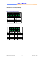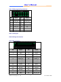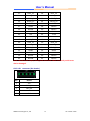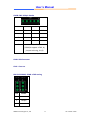
1
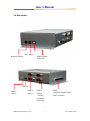
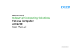
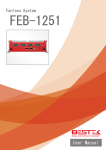
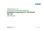
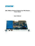
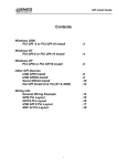
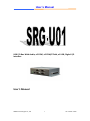
User’s Manual
USB I/O Box With Audio, x2 COM, x2 COM/CCtalk, x1 USB, Digital I/O
interface
User’s Manual
AEWIN Technologies Co., Ltd
1
Ver 1.0 Dec. 2013
User’s Manual
© Copyright 2010.
All Rights Reserved
Manual Edition 1.0, September, 2012
This document contains proprietary information protected by copyright.
All rights are reserved; no
part of this manual may be reproduced, copied, translated or transmitted in any form or by any means
without prior written permission of the manufacturer.
The content of this document is intended to be accurate and reliable; the original manufacturer
assumes no responsibility for any inaccuracies that may be contained in this manual.
The original
manufacturer reserves the right to make improvements to the products described in this manual at
any time without prior notice.
Trademarks
IBM, EGA, VGA, XT/AT, OS/2 and PS/2 are registered trademarks of International business Machine
Corporation
Award is a trademark of Award Software International, Inc
Intel is a trademark of Intel
RTL is a trademark of Realtek
VIA is a trademark of VIA Technologies, Inc
Microsoft, Windows, Windows NT and MS-DOS are either trademarks or registered trademarks of
Microsoft Corporation
All other product names mentioned herein are used for identification purpose only and may be
trademarks and/or registered trademarks of their respective companies
Limitation of Liability
While reasonable efforts have been made to ensure the accuracy of this document, the manufacturer
and distributor assume no liability resulting from errors or omissions in this document, or from the
use of the information contained herein.
For more information on SRG-U01 or other AEWIN products, please visit our website
http://www.aewin.com.tw.
For technical supports or free catalog, please send your inquiry to
[email protected]
AEWIN Technologies Co., Ltd
2
Ver 1.0 Dec. 2013
User’s Manual
Revision History
Rev.1.0
Original copy
AEWIN Technologies Co., Ltd
3
Ver 1.0 Dec. 2013
User’s Manual
Table of Content
Chapter 1. General Information ..................................................................................... 5
1.1 Introducing ....................................................................................................... 5
1.2 Specification ..................................................................................................... 5
1.3 Order Information ............................................................................................ 7
1.4 Packaging.......................................................................................................... 7
1.5 Precautions ...................................................................................................... 7
1.6 Box System ....................................................................................................... 9
1.7 Board / System Dimension ............................................................................. 10
Chapter 2. Connector/Jumper Configuration .............................................................. 11
2.1 Connector/Jumper Location and Definition .................................................. 11
2.2 Connector and Jumper Setting ...................................................................... 14
Appendix : Development Kit (optional) ....................................................................... 18
AEWIN Technologies Co., Ltd
4
Ver 1.0 Dec. 2013
User’s Manual
Chapter 1. General Information
1.1 Introducing
SRG-U01, a miscellaneous I/O control box for variety applications, like gaming
machine, POS, machine automation …etc. The box with x1 USB 2.0, x1 audio
(line-out), x2 COM, x2 COM/CCtalk (by jumper setting), digital I/O. support Windows
7 and Windows Embedded Standard 7.
1.2 Specification
■ Audio
Audio
■ Gaming
Digital I/O
■ System I/O
COM
USB
x1 Line-out
24 x photo-couple isolated input
24 x 500mA current sink output
4 x COM
․COM1 support Full RS-232 (external DB9)
․COM2 support Full RS-232 (external DB9)
․COM3 support Full RS-232 or cctalk (jumper select)
․COM4 support Full RS-232 or cctalk (jumper select)
1 x USB2.0, type B, the interface to host
1 x USB2.0, type A.
■ Power Supply
Voltage
DC 5V/2A power adapter
■ Software
O/S
Microsoft® Windows® 7/ Windows® Embedded Standard7
■ Mechanical and Environment
Environmental
Operating Temperature: 0 – 60 ºC (32 ºF – 140 ºF)
Storage Temperature: -20 – 85 ºC (-4 ºF – 185 ºF)
Relative Humidity: 10-85 % RH, non-condensing
Compliant
FCC/CE Class A; ESD
Dimension
172mm(L) x 105mm(W) x 42mm(H)
■ Applications
AEWIN Technologies Co., Ltd
5
Ver 1.0 Dec. 2013
User’s Manual
Main Application
Gaming
Video slot machines
Fruit machines
Video lottery terminals
Amusement game machines
Betting terminal of multiplayer table game or roulette
POS station
AEWIN Technologies Co., Ltd
6
Ver 1.0 Dec. 2013
User’s Manual
1.3 Order Information
SRG-U01A
USB I/O Box With Audio, x2 COM, x2 COM/CCtalk, x1 USB, Digital
I/O interface
Optional
DK-SRGU01-01 Development Kit include R217A Gaming I/O testing board
* Note: All specifications are subject to change without prior notice
1.4 Packaging
Please make sure that the following items have been included in the package before
installation.
1. SRG-U01 box
2. Quick Installation Guide (Optional)
3. Cables (Optional)
4. CD-ROM that contains the following folders:
(1) Manual
(2) Driver
If any item of above is missing or damaged, please contact your dealer or retailer
from whom you purchased the SRG-U01. Keep the box and carton when you
probably ship or store SRG-U01 in near future. After you unpack the goods, inspect
and make sure the packaging is intact. Do not plug the power adapter to the
appliance of SRG-U01 if you already find it appears damaged.
Note: Keep the SRG-U01 in the original packaging until you start installation.
1.5 Precautions
Please make sure you properly ground yourself before handling the SRG-U01 box or
other system components. Electrostatic discharge can be easily damage the SRG-U01
box.
Do not remove the anti-static packing until you are ready to install the SRG-U01 box.
AEWIN Technologies Co., Ltd
7
Ver 1.0 Dec. 2013
User’s Manual
Ground yourself before removing any system component from it protective
anti-static packaging. To ground yourself, grasp the expansion slot covers or other
unpainted parts of the computer chassis.
Handle the SRG-U01 box by its edges and avoid touching the components on it.
AEWIN Technologies Co., Ltd
8
Ver 1.0 Dec. 2013
User’s Manual
1.6 Box System
DC +5V/2A
Device ID switch
USB2.0 Type B
To Host PC
USB 2.0
Audio
Line-in
COM 2
COM 4
GPIO
COM 1
COM 3
(CCTalk,
by jumper
selecting)
x24 Photo-coupler input
x24 TTL output
AEWIN Technologies Co., Ltd
9
Ver 1.0 Dec. 2013
User’s Manual
1.7 Board / System Dimension
172mm(L) x 105mm(W) x 42mm(H)
AEWIN Technologies Co., Ltd
10
Ver 1.0 Dec. 2013
User’s Manual
Chapter 2. Connector/Jumper Configuration
2.1 Connector/Jumper Location and Definition
Connector:
Connector
Description
CN1
SPI programming connector
CN2
LPC connector
CN3
FPGA programming connector
CN4
+5V DC jack
CN5
USB Type A connector
CN6
GPIO connector
CN7
USB connector (Pin Header)
CN8
COM1/COM2 connector
CN9
COM3/COM4 connector
CN10
USB Type B connector
AEWIN Technologies Co., Ltd
11
Ver 1.0 Dec. 2013
User’s Manual
CN11
Audio connector
J1
I2C connector
AEWIN Technologies Co., Ltd
12
Ver 1.0 Dec. 2013
User’s Manual
Jumper:
JP1
3.3V for FBGA pump signal
JP2
RS-232 / CC talk select (COM3)
JP3
RS-232 / CC talk select (COM4)
JP4
CC talk signal / RI signal select (COM3)
JP5
CC talk signal / RI signal select (COM4)
JP1
1-2 On: 3.3V
1-2 Open: normal
JP2
1-3, 2-4: RS-232
3-5, 4-6: CC talk
JP3
1-3, 2-4: RS-232
3-5, 4-6: CC talk
JP4
1-2: RS-232
2-3: CC talk
JP5
1-2: RS-232
2-3: CC talk
AEWIN Technologies Co., Ltd
13
Ver 1.0 Dec. 2013
User’s Manual
2.2 Connector and Jumper Setting
CN1: SPI programming connector
Pin
Define
Pin
Define
1
+5V
2
GND
3
XRES
4
MOSI
5
SCLK
CN2: LPC connector
Pin
Define
Pin
Define
1
FTCK
2
GND
3
FTDO
4
5
FTMS
6
VJTAG
7
VPUMP
8
FTRST
9
FTDI
10
GND
AEWIN Technologies Co., Ltd
14
Ver 1.0 Dec. 2013
User’s Manual
CN3 : FPGA programming connector
Pin
Define
Pin
Define
1
N/C
2
FPGA_AD0
3
FPGA_AD1
4
FPGA_AD2
5
FPGA_AD3
6
FPGA_FRAME_N
7
FPGA_RST_N
8
N/C
9
FPGA_CLK
10
N/C
11
GND
12
N/C
13
FGPA_IRQ
14
N/C
CN4 : +5V DC jack
CN5: USB Type A connector
CN6: GPIO connector
Pin
Define
Pin
Define
1
+5V
2
Ext_5V_IN
3
GND
4
GND
5
Ext_5V_IN
6
GPI1_5V
7
GPI4_5V
8
GPI7_5V
9
GPI10_5V
10
GPI13_5
11
GPI16_5
12
GPI19_5V
13
GPI22_5V
14
GPO1
15
GPO4
16
GPO7
17
GPO10
18
GPO13
19
GPO16
20
GPO19
21
GPO22
22
+5V
23
+3.3V
24
GND
25
GND
26
Ext_5V_IN
AEWIN Technologies Co., Ltd
15
Ver 1.0 Dec. 2013
User’s Manual
27
GPI2_5V
28
GPI5_5V
29
GPI8_5V
30
GPI11_5V
31
GPI14_5
32
GPI17_5
33
GPI20_5V
34
GPI23_5V
35
GPO2
36
GPO5
37
GPO8
38
GPO11
39
GPO14
40
GPO17
41
GPO20
42
GPO23
43
+5V
44
+3.3V
45
GND
46
GND
47
GPI0_5V
48
GPI3_5V
49
GPI6_5V
50
GPI9_5V
51
GPI12_5
52
GPI15_5
53
GPI18_5V
54
GPI21_5V
55
GPO0
56
GPO3
57
GPO6
58
GPO9
59
GPO12
60
GPO15
61
GPO18
62
GPO21
Note : Attention on output, driving load more than 50mA constantly could cause
device damaged.
CN7: USB connector (Pin Header)
Pin
Define
1
+5V
2
DMU_R2
3
DPU_R2
4
GND
5
GND
AEWIN Technologies Co., Ltd
16
Ver 1.0 Dec. 2013
User’s Manual
CN8 & CN9: USB pin header
Pin
Define
Pin
Define
1
DCD
2
RXD
3
TXD
4
DTR
5
GND
6
DSR
7
RTS
8
CTS
9
RIA / ccTalK
(COM3,4 support ccTalk, by
jumper selecting, JP4,5)
CN10: USB Connector
CN11 : Line-out
JP4 & JP5:COM3, COM4 ccTalk setting
Pin
Define
1
COM
2
Output
3
ccTalk
AEWIN Technologies Co., Ltd
17
Ver 1.0 Dec. 2013
User’s Manual
Appendix : Development Kit (optional)
The SRG-U01 offers R217A Gaming I/O testing board and some cables for
development usage.
DK-SRG-U01
Item & Description
Gaming I/O testing board
72 pin golden finger cable
Part No.
R217A-01
46L-G00031-00
46L-G00031-00
R217A-01
AEWIN Technologies Co., Ltd
Qty
1
1
18
Ver 1.0 Dec. 2013