1
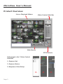
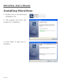
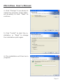
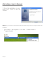
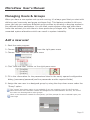
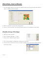
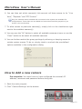
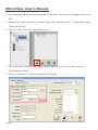
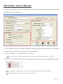
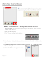
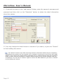
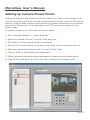
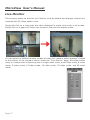
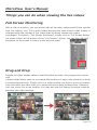
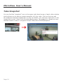
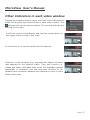
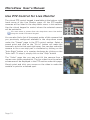
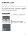
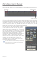
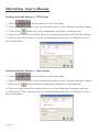
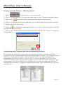
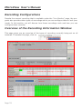
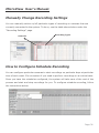
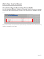
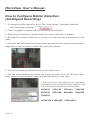
User’s Manual
MicroView User’s Manual
Table of Contents
Product Overview
System Requirements
Installing MicroView
Managing Users & Groups
Add a new user
Modify Group Privilege
How to Add a new camera
Add a new camera -- using the search tool
Setting up Camera Preset Points
Live Monitor
Things you can do when viewing the live videos
Full Screen Monitoring
Drag and Drop
Take Snapshot
Other Indicators in each video window
Use PTZ Control for Live Monitor
Configuring and Using Sequence View
E-Map Monitor
Setting up E-Map
Playback
Export Playback Videos to Local Hard Disk
Configuring Event Servers and Event Actions
Setting up Event Servers — Mail Server
Setting up Event Servers — FTP Server
Setting up Event Servers — Alert Server
Setting up Event Servers — Warning Server
Configuring event triggers and the corresponding actions
Recording Configurations
Overview of the Recording Information Window
Manually Change Recording Settings
How to Configure Schedule Recording
How to Configure Recording Frame Rate
How to Configure Motion Detection (Intelligent Recording)
Multiple Displays Monitoring
Change the System Display Language
Quickly check all cameras’ status
Start the program during Windows startup
System Log and System Info
3
4
5
8
8
9
10
13
16
17
18
18
18
19
20
21
22
23
24
26
28
30
30
31
31
32
32
33
33
34
34
36
37
39
40
41
41
42
Page 2
MicroView User’s Manual
Product Overview
Live or Playback Videos
Video Control Side Bar
Main Menus
PTZ Controls
Sub-pages in the “Video Control
Side Bar”
1. Camera List
2. Camera Status
3. Sequence View Setup
1.
Page 3
2.
3.
MicroView User’s Manual
System Requirements
The following are minimum system requirements for the system running MicroView:
Operating System
Microsoft® Windows® 2000 Professional, Windows® XP Professional (32 bit) or Windows® Server 2003 (32 bit)
CPU
Minimum Intel® Pentium® 4 2.4 GHz or higher (Dual Core is recommended)
RAM
Minimum 1 GB of RAM, 2GB or above is recommended
Network
Minimum 10/100 Ethernet (Gigabit Ethernet is recommended)
Graphics Adapter
AGP or PCI-Express, minimum 1024x768, 16 bit colors.
(We highly recommend to work at 1280 x 1024 resolution to get the full experience of
the software)
.
.
Make sure your display DPI setting is set to default at 96DPI
To set DPI value, right-click on desktop, choose “Settings” tab >> “Advanced” >> “General”
Hard Disk Type
E-IDE, PATA, SATA, SCSI (7200 rpm or faster).
Hard Disk Space
200 GB free (depends on number of cameras and recording settings).
Page 4
MicroView User’s Manual
Installing MicroView:
1. Double click on the MicroView
installation file
2. The program will start and
prepare for installation
3. Click “Next” to start the installation
Page 5
MicroView User’s Manual
4. Click “Change” if you desire to
install the program under different directory or click “Next” to
continue
5. Click “Install” to start the installation or “Back” to change
the installation path again
6. The installation will then be in
progress
Page 6
MicroView User’s Manual
7. Once the installation is complete, click “Finish” to exit the
installer
Note: If you choose to launch MicroView at a later time, there is a way to launch the
program:
. From Start > All Programs > P C N V R > 36CH PC NVR >
> 36CH PC NVR
Page 7
MicroView User’s Manual
Managing Users & Groups
When you have a new system set up and running, it’s always good that you start with
defining user’s accounts and group privileges first. This feature provided in this program can help you configure different group profiles by allowing or denying access to
pre-defined system parameters. You can then create system users and place them
under the account you wish them to have particular privileges with. This can prevent
unwanted system alterations which can result in system instability.
Add a new user
1. Start the main program
2. Choose
from the right-pane menu
3. Choose “User” from the left-pane menu
4. Click “Add new user” button on the right-pane menu
5. Fill in the information for the parameters listed in the newly opened configuration
dialog (username/password/confirm passwords are the required fields)
6. Assign the new user to a designed group by using the drop-down menu under the
“Group” option
The “Group” drop-down option is not available if you are creating a user for the first time.
Once there’s an user that was created and assigned to the administrator account, the rest of
the users can be assigned to other groups.
Once a user has been created for the system, you’ll be prompt for user credential upon your
next login
Page 8
MicroView User’s Manual
7. You may add a photo for the user by double clicking on the photo area and select a
photo in JPEG or GIF file format
8. Click on “Submit” to finish the configuration
9. Click on “Save and Exit” from the left-pane menu for the settings to take effect
Modify Group Privilege
1. Start the main program
2. Go to “System Settings” > “User”
3. Click on the “Modify Group” button
4. The “Group Setting” configuration dialog should pop up
5. Choose which account you wish to make changes to by using the “Group Setting”
drop-down menu
Page 9
MicroView User’s Manual
6. You can then set which camera(s) this account will have access to for “Live
View”, “Playback” and “PTZ Control”
Only the cameras that are added and connected to the system are available for
configurations. Those that are not added and connected would be grayed out (as
shown in the screenshot)
7. To allow access to particular camera(s), simply click on the checkboxes right
next to the available camera(s)
8. You may use the “All” button to select all available cameras at once or use the
“Clear” button to de-select all available cameras
9. You can further restrict the group privilege by allowing or denying access to
certain system menus. To do so, simply check or uncheck the pre-defined
options available in the configuration dialog
How to Add a new camera
Pre-requisite: You must know or have configured the camera’s IP
address, username and password before doing this
1. Start the main program
2. Click “Camera Settings” at the bottom
Page 10
MicroView User’s Manual
3. A configuration dialog should pop and a tree-view menu should be available on the
left.
4. Expand the “Manual Assign Camera” option by clicking on the “+” sign and choose
“Camera Setting”
6. Click on “Add” from the right-pane menu
7. Fill in the fields listed in the “Video Device Search” box in the newly pop-up
configuration dialog
8. Click on “Detection” button to detect the camera
Page 11
MicroView User’s Manual
9. Once the camera is properly detected, the rest of the camera’s configurations should
be polled from the camera
10. You should be able to change camera’s settings such as video format, or resolution
at this point by using the drop-down menu provided
11. Click “Submit” to finish adding the camera
You may click the “Video” button to get a preview video from the camera if you wish
12. Click “Exit with Save” to save the configuration and leave the configuration dialog
To change the configuration of a camera, highlight one in the list and click “Edit”
To undo adding or removing a camera, click “Cancel”
Page 12
MicroView User’s Manual
To remove a camera, highlight the one you wish to remove
in the list and click “Edit” to open the configuration dialog. In the
configuration dialog, click “Remove” to remove the camera
Add a new camera -- Using the Smart Search
Pre-requisite: The station that is performing the search must be on the same
subnet as the cameras
1. Start the main program
2. Click “Camera Settings” at the bottom
3. A configuration dialog should pop and a tree-view menu should be available on the
left
4. Expand the “Manual Assign Camera” option by clicking on the “+” sign and choose
“Camera Setting”
6. Click on “Add” from the right-pane menu
Page 13
MicroView User’s Manual
7. Click on “Search” button without filling in any information to search the cameras
available on the network
8. The status bar should be displayed during the search
9. If you have firewall installed and turned on, a warning message should pop up to ask
the permission for the connection. Please go ahead and acknowledge it
10. Results will then be shown. Just double-click on the one you wish to add to the
system
Page 14
MicroView User’s Manual
11. It should the return to the “add camera” dialog, enter the camera’s username and
password and then click on the “Detection” button to obtain the detail information
about the camera
12. You may change the video format or resolution if you desire, or just click “Submit”
to finish adding the camera
The “Search” function may finish retrieving camera’s information before they are completely
transmitted to the system over the network, thus, resulted in retrieving a 00-00-00-00-00-00 MAC
address. This is due to the network latency especially from a wireless camera which the connection
might be easily interfered sometimes. It doesn’t affect anything if the camera is added under this
circumstance. You can click on “Search” again to retrieve the MAC address or just click on “Submit”
to finish adding the camera
Page 15
MicroView User’s Manual
Setting up Camera Preset Points
Setting up camera preset points can come in handy from time to time because it allows you to quickly switch the camera monitoring point without using the PTZ control
buttons. Simply create multiple preset points on locations that need to be monitored
and a list of these points will be available in the PTZ control area under the Live
Monitor page.
To create a preset point, follow the instructions below:
1. Go to “Camera Settings” > “Preset Positions”
2. Select the camera from the “Channel” drop-down list
3. The video from that camera should be displayed
4. Use the PTZ control buttons to set where you would like the camera to point to
5. After that, name this position in the “Current Position” field
6. Click on “Add” to finish adding the preset point.
7. Follow the same instructions described above to create multiple preset points
8. Click on “Exit with Save” when you are done configuring the preset points
Page 16
MicroView User’s Manual
Live Monitor
The program starts up with the Live Monitor view by default and displays videos from
cameras with 36-video pattern view.
Single left-click on a video gets the video displayed in single view mode in full screen.
Single click on it again will return the screen to the previous display mode.
You can switch to different display modes by using the “pattern switch buttons” located
at the bottom of the program screen under the “Live Monitor” page. MicroView allows
users to configure the monitoring area in single video mode, quad video mode, 6-video
mode, 9-video mode, 13-video mode, 16-video mode, 25-video mode, and 36-video
mode.
Page 17
MicroView User’s Manual
Things you can do when viewing the live videos
Full Screen Monitoring
With a click of a button, you can quickly hide all the menu options and fill the monitor
with live video(s) only. This is quite helpful because the scale of each video window is
enlarged while the number of live videos that are being viewed can remain
unchanged. To switch to “Full Screen Monitoring”, simply click on “Full Screen Button”
(as shown below) at the bottom of the “Live Monitor” screen. You can then left-click
anywhere on the screen to return to the previous state.
Drag and Drop
Despite the video display patterns that MicroView provides, the program also comes
with
a feature that allows users to re-arrange the locations of each video window by doing
a simple drag and drop. Simply click on a video window you wish to move its location
from and move the video with your mouse left button keep holding down. Release it
until you move it to a new location. You may also use this feature to switch locations
between two video windows.
Page 18
MicroView User’s Manual
Take Snapshot
You can find the “snapshot” icon on the upper-right hand corner of each video window
which allows you to take an instant snapshot of a live video. Click on the icon and
the snapshot should be displayed in a pop up window. You can then right-click on the
image and choose “Save” from the drop-down menu. The snapshot is saved at a predefined location under C:\Program Files\PC NVR\36CH PCNVR\Snapshot
Path[C:\Program Files\PC NVR\36CH PCNVR\Snapshot\]
Page 19
MicroView User’s Manual
Other Indicators in each video window
Despite the snapshot button, there are three other indicators resides on the upper-right hand corner in each video window. The
indicates the current camera status. The camera statuses are
defined on the right.
It will turn on the motion display and mark an overlay paint on
the object that’s moving in the video
It will allow you to receive audio from the camera
Overtime, some cameras may automatically adjust its frame
rate depends on the network traffic. They don’t tend to increase the frame rate back even when the available network
bandwidth is increased. Use the reconnect function to reestablish the connection between the cameras in order to get a
better frame rate
Page 20
MicroView User’s Manual
Use PTZ Control for Live Monitor
The virtual PTZ control keypad is available at the bottom-right
hand corner of the Live Monitor page. All the PTZ-capable
cameras will be listed in the drop-down menu in this section.
Use the virtual keypad to control where the selected camera
will be pointed to.
You must select a camera from the drop-down menu first before
using the virtual PTZ control keypad
You can also find a list of the preset points of this camera that
you previously configured available in the drop-down menu
under the “Preset” page in the PTZ control section. Select a
preset point and click on the “Go to” button will make the
camera to point to that spot right away. You can also make the
camera to do a non-stop pan in clockwise by clicking on the
“Auto Right” button or in counter-clockwise by clicking on the
“Auto Left”. To stop it, simply click on the “Stop” button
The “Video” page lets you pan and tilt the camera from a
mouse-over-video perspective. The live video from the selected camera will be displayed in the PTZ section under this page.
Simply point and click your mouse on the video to make the
camera to point to a desired spot.
Page 21
MicroView User’s Manual
Configuring and Using Sequence View
Sequence view is a feature that allows you to perform live monitoring from multiple
cameras and have the system automatically switch those live videos for you with a time
interval you desire. You can set the system to run the sequence view under different
screen split modes and display, for example, four videos at once and then display the
other four in sequence. You can manually pick out the cameras that you wish to perform
the sequence view on, or simply select to sequence them all. Below are the
instructions to setting up the sequence view function:
1. Under the “Live Monitor” page, click on the “SEQ” tab under the main menu
2. Different screen split modes will be available depends on the number of cameras
that are currently connected to the system. For example, if there is only three
cameras connected to the system, only the single view mode will be available.
3. Select a desired screen split mode
4. Set the time interval for the sequence view (time is calculated by second)
5. Accept the default setting to sequence all cameras or select “Manual SEQ” and then
pick the cameras from the list below
Page 22
MicroView User’s Manual
E-Map Monitor
E-Map monitor is a function that alerts users whenever there is an event triggered (e.g.
motion detected) from a camera with a geographical perspective. With this function,
users can quickly identify which camera has detected an unusual event and where this
event is happening. This function works by incorporating the event detection function
as well as the recording function, which, as a result, helps users take all the necessary
actions when an unusual event occurs. In order for this function to work properly, the
following functions would need to be configured first:
. E-Map: Insert your own map and its sub-maps and set the cameras’ locations by
moving the icons embedded in the map.
. Motion Detection: Setup motion detection for the cameras. (See page 37 — how to
configure motion detection)
Once you have them set up properly, you should see something similar to what’s
shown in the screenshot on the right.
You should get a view of the main map
displaying the location of each camera
group. On the right-pane menu, you
should get the tree-view list of all the
cameras. Once there’s a motion
detected from one or more cameras,
you will see live videos pop up on the
main map and the sub-maps will be
displayed at the bottom-right hand
corner to inform users which and where
the camera is detecting the motion.
gets you to a new window where you can search and playback the
Click on the
videos recorded by the motion detection. Click on the “Search” button and a list of
results should be displayed. Click on the
result will start the playback process and
the playback video will be displayed on
the upper-left hand corner area with its
information displayed in the area right
next to it. The sub-map which
represents the location of the camera
will be displayed on the upper-right hand
corner window. Results that were played
will be highlighted in pink to represent
that they were previously being played
Page 23
MicroView User’s Manual
Setting up E-Map
1. Start the program
2. Select “System Settings” from the right-pane menu
3. Select “E-Map Setting” from the left-pane menu
4. The main map and the sub-maps should be listed
in the configuration dialog
Main Map
Sub-Maps
5. You can rename the map name in the
“Name” field and create an OSD
(On Screen Display) message in the “OSD” field. They will be displayed on the upperleft hand corner of the map.
6. The main map displays the locations of the cameras in groups. Double-click on the
map to replace with your own
7. The larger-scale view of the map should be displayed
Page 24
MicroView User’s Manual
8. Double-click on the map again and you should be prompted to locate the new map
9. Locate the new map and click “OK” to confirm your selection
10. Notice that there are icons on the upper-left hand corner of the map which represent camera groups.
11. You can click and hold down the mouse
left key on any one of them to move it to a
desired location on the map
12. Click on the “save setting” button on the upper-right
hand corner to save your setting
13. Click “OK” to acknowledge the change
14. Now you would want to divide the main map to six smaller
ones (sub-maps) which represents six different areas on the main map.
15. Double-click on the group 1 sub-map in the
sub-maps area to replace the map. Edit the map
name and OSD message if you desire.
16. The group 1 sub-map should have icons on the
upper-left hand corner which display cameras that
are assigned in group 1.
17. Click and hold down the mouse left key to move
the icons to define the locations of each cameras.
Page 25
MicroView User’s Manual
18. When you are done, simply click on the
button to exit the dialog.
19. Repeat the steps 16 to 18 to configure the rest of the sub-maps.
Playback
Playback is a function that allows you to play videos that were previously recorded
from one or more cameras. The program allows you to playback videos in single view
mode or quad view mode. Multiple videos recorded from different cameras (up to
four) can be played on a quad view screen at the same time. The program provides
certain ways for searching playback videos.
You can perform a search by choosing one or more cameras
listed at the bottom right hand corner. Once you have selected
the camera(s) you wish to perform a search on, click on the
“Search” button to narrow down the search criteria with the
options provided by the program. Icons shown in gray mean
those channels are not available, the ones shown in purple are
available but are not chosen to perform search on yet. The one marked in blue are
the ones that are chosen to perform search on.
Page 26
MicroView User’s Manual
Result will then shown in the area available in the bottom left-hand corner.
year/month
date/hour/min
found recording
Click on a cell marked in blue will narrow down the search result and show
all recordings found in that time frame. It will then start playing back the
recording. If there are recordings found in other cameras (the ones you
chose to perform search on) around the same time frame, they will be
played on the screen as well (synchronized playback)
You can click on the “Event Search” button
on the right-pane menu to filter the search
results with event recordings only. The results
will then be displayed in thumbnails. Pointing
the mouse cursor on one of the thumbnails will
show you the video information of which
channel the recording was taken and when it
was taken. Click on a thumbnail will start
playing back the video and videos from other
cameras will also be played if there are
recordings found in those other cam- eras
around the same time frame.
You may reduce the search result by specifying a
event start time in the “Begin Time” section for
continuous event search
Page 27
MicroView User’s Manual
Export Playback Videos to Local Hard Disk
The program allows you to export the playback videos and save them to a local hard
disk as AVI files. User can then use Windows Media Player to playback the videos.
After you allocate the recorded videos with steps described in page 26 and 27. You
can then select a channel (one at a time) from the left menu (shown below) to start
exporting the video. Simply click “Start” after you select a channel
A start time of a recorded video will be displayed to confirm the exporting, click “Convert” to start:
The process status should be displayed, you may click “Stop” to cease the process at
anytime:
Page 28
MicroView User’s Manual
You can quickly access the folder where the exported videos are saved by
using the shortcut icon:
The exported AVI files should be saved in the “AVI” folder created under the
directory where the program is installed:
* The AVI files are saved under the C:\Program Files\PC NVR\36CH PCNVR\AVI
folder by default.
* You would need the following codecs in order to playback the exported videos with Windows Media
Player:
1. DirectX MJPG codec to playback videos recorded in the MJPEG format, you can download
it here: http://www.wmplugins.com/ItemDetail.aspx?&codec=MJPG
2. XViD or FFMPEG codec to playback videos recorded in the MPEG4/H.264 format. Download links are shown below:
XViD: http://www.xvid.org/Downloads.15.O.html
FFMPEG: http://www.ffmpeg.org/
You can ultimately use a third-party media player that has all the popular codecs preinstalled at your convenience.
Page 29
MicroView User’s Manual
Configuring Event Servers and Event Actions
Event servers can be used as an automated system and send out instant notifications
the moment there is an event triggered by the camera or the system. The program
offers four different types of servers which mean four different types of notifications
can be sent upon triggers of one or multiple events. You can add up to three severs
for each type and select which one(s) to use when a particular event occurs. You are
also able to include still images and text files as part of the notification when it’s sent
to an e-mail or a FTP server.
Setting up Event Servers — Mail Server
1. Select
at the bottom in Live View page
2. Click on “Event Settings” from the left-pane menu in the “System Settings” dialog
3. Click on the
button and the configuration like below should pop up.
4. Click on a mail server list would allow you to start configuring the sender and
recipient’s information
5. Click on the “Test” button to verify the information and click on “Submit” to save
the configuration
Page 30
MicroView User’s Manual
Setting up Event Servers — FTP Server
1. Select
at the bottom in Live View page
2. Click on “Event Settings” from the left-pane menu in the “System Settings” dialog
3. Click on the
button and the configuration like below should pop up.
4. Click on a FTP server list would allow you to start entering the FTP server settings.
5. Click on the “Test” button to verify the information and click on “Submit” to save
the configuration
Setting up Event Servers — Alert Server
1. Select
at the bottom in Live View page
2. Click on “Event Settings” from the left-pane menu in the “System Settings” dialog
3. Click on the
button and the configuration like below should pop up.
4. Click on a Alert server list would allow you to start entering the server settings.
5. Click on the “Test” button to verify the information and click on “Submit” to save
the configuration
Page 31
MicroView User’s Manual
Setting up Event Servers — Warning Server
1. Select
at the bottom in Live View page
2. Click on “Event Settings” from the left-pane menu in the “System Settings” dialog
3. Click on the
button and the configuration like below should pop up.
4. Click on a warning server list would allow you to start entering the server settings.
5. Enter a name for the profile
6. Click on
to locate the warning sound file (in .wav) or skip this step to use the
pre-defined warning sound.
7. Click on the “Test” button to verify the sound file and click on “Submit” to save the
configuration
Configuring event triggers and the corresponding actions
In the previous section, we have gone through the process of configuring event
servers. They can now be used as actions during trigger of events. The program comes
with a list of pre-defined events and activating them is as simple as ticking the
checkboxes right next to them. Click on the “+” sign of an event will allow you to
select the event servers you previously added. You can use the list to create your own
event trigger rule with combinations of triggering one event and send notifications to
multiple event servers or triggering multiple events and send notifications to only one
event server.
Page 32
MicroView User’s Manual
Recording Configurations
Despite the manual recording that is available under the “Live Monitor” page, the program also provides other types of recordings which you can configure them to suit your
needs. In this section, we will discuss how these recordings work and how you can
configure them correctly.
Overview of the Recording Information Window
This page gives you an overview of the types of recording currently being set on all
cameras. To access this page, click on
Information of where the recorded videos are saved
Information of cameras with what type of recordings are
being enabled
Detail information of schedule recording on all
cameras
Page 33
MicroView User’s Manual
Manually Change Recording Settings
You can manually switch on/off particular types of recording on cameras that are
currently connected to the system. To do so, use the table shown below under the
“Recording Settings” page.
Cameras
Recording Types
How to Configure Schedule Recording
You can configure particular cameras to start recordings on particular days at particular
time of each week. It’s convenient if you need to perform recordings on a routine basis.
Once you have the schedules configured, the system will take care of the rest of the
process and start and stop recordings for you. To configure schedule recording, follow
the instructions below:
Page 34
MicroView User’s Manual
1. Select a camera from the “Channel” drop-down menu under the “Scheduling”
section in “Recording Settings” page
2. Now use the time table below to specify the start time and end time of the schedule
recording
3. Check one or more cell box(es) to specify the time range and each cell box
represents 15 minutes of time
4. You can left-click on a cell box and move the mouse vertically with the left-key
continue holding down to schedule a recording to be performed at the same hour of
those consecutive days.
5. You can also left-click on a cell box and move the mouse horizontally with the leftkey continue holding down to schedule a recording to be performed for consecutive
hours in that day
6. Use the Day/Night/Weekend options allows you to quickly schedule a recording to
be performed during the daytimes on the weekdays, night-times on the weekdays or
whole days during the weekend
7. Click on “Exit with Save” to save the configuration
Page 35
MicroView User’s Manual
How to Configure Recording Frame Rate
You can set the frame rate to be used for a particular type of recording by manually
changing the values in the options provided at the bottom of the “Recording Settings”
page.
Click on a box that’s corresponded to a particular type of recording and video streaming
mode to change the frame rate.
Page 36
MicroView User’s Manual
How to Configure Motion Detection
(Intelligent Recording)
1. To configure motion detection, go to “Rec” then choose “Intelligent Detection”
in the newly pop-up dialog
2. Click to highlight a camera and you should see its live video.
3. Make sure its checkbox is ticked so that the motion detection is enabled
4. By default, the motion detection is turned on to scan the whole area shown in the
video
5. Left-click and hold down the mouse button anywhere on the video area and drag it
diagonally to draw a square to define an area to be scanned
6. The area will then be highlighted with white small circles
7. You can choose different colors for the circles from the “Color for MD area” dropdown menu in case the small circles can’t be seen clearly on the video
* There are certain resolutions are not supported in
the program when configuring motion detection. Use
only the following resolutions for this function:
160x120
176x120
176x144
320x240
352x240
352x288
640x480
704x480
704x576
1024x768 1280x960
Page 37
1280x1024
MicroView User’s Manual
8. Next, make the selection of how the moving object will be marked on the screen from
the “Motion Display Mode” drop-down menu. (Sample photo is provided along with the
selection you make) The menu provides different styles of overlay object or paint with
different colors that can be used to placed on the moving object in the live video. This
can quickly help users identify the object that is moving in the live video.
9. Then click on “Exit with Save” from the left pane menu and the restart the program
for the settings to take effect.
10. Once you come back to the program and from the live video which you just set up
the motion detection on, click on
on the top bar of the live video window to turn on
motion display for the video and you should see the moving object in the video marked
with the overlay paint you just selected during the motion detection configuration
Page 38
MicroView User’s Manual
Multiple Displays Monitoring
Features like Live Monitor, E-Map Monitor or Playback are opened in separate windows,
and working under a particular window can sacrifice the views of others. If you have
multiple displays set up in your environment, the program allows you to define which
display the window will be opened on and give you the flexibility to display up to three
windows onto three different displays every time you use those particular functions. To
configure this function, follow the steps described below:
1. Click on
at the bottom in Live View page
2. A configuration dialog should pop up and the number of displays on your system
should be automatically detected.
3. A list of the functions that can be rearranged to be opened onto different displays
will be shown on the left
4. Simply drag and drop one onto a large virtual display icon on the right to complete
the rearrangement.
Mouse drag’n drop
5. Click on “Save” to finish the configuration.
Page 39
MicroView User’s Manual
Change the System Display Language
MicroView allows users to switch program display language on the fly. You can set
up the display language in the initialization program or in the main program. By
default, MicroView starts up displaying the same language as the operating system it
installs on.
1. Start the main program
2. Click on
at the bottom in Live View page
3. A new configuration dialog should open. Choose “General Setting” from the leftpane menu under the “General Option”
4. Use the drop-down menu to select the program display language under the
“Language” option from the right-pane menu
5. Click “Save and Exit” from the left-pane menu for the settings to take effect and
leave the configuration dialog
A quick way to change the system language is to use the drop-down menu from the “HELP” option
in the right pane side bar and select a desired language for the system.
Page 40
MicroView User’s Manual
Quickly Check All Cameras’ Status
MicroView offers a great way to quickly check all cameras’ status while you are
doing the live monitoring. You can access such information by going to the “Status”
tab under the “Live Monitor” page at the top of the right-pane main menu section.
Click on the “Status” tab will replace the main menu with camera status table that’s
shown below. You can now get the most up-to-date status of all cameras and view the
live videos at the same time.
Start the Program During Windows Startup
MicroView can be configured to either start automatically during the Windows startup or
to start silently as a service. You can configure this under “System Settings” > “General
Settings” > “Startup”. Check either one of the three options provided to customize the
startup options.
Page 41
MicroView User’s Manual
System Log and System Info
The system log and system info are displayed at the bottom of the “Live Monitor”
page, allowing you to know what is going on with the system while you are doing
the live monitoring. The system log works by giving you instant notifications that
keeps piling up whenever there is change made to the system. It gives you
information of what changes have been made and when those changes were made.
The system info lets you know the current system time, which is currently logged in
and how many hours of recording space is left on your system.
What’s been changed
When they were changed
Page 42