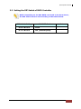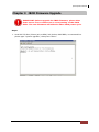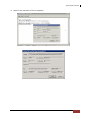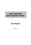
1
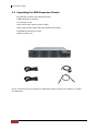
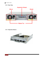
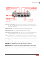
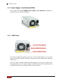
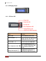
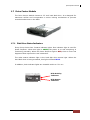
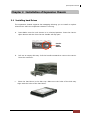
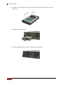
SAS to SAS/SATA Epica Expansion Chassis User Manual Revision 1.0 Epica Expansion Chassis Table of Contents Chapter 1 Introduction .................................................................................................... 3 1.1 Features .............................................................................................................................................................................. 4 1.2 Technical Specifications ............................................................................................................................................... 5 1.3 Unpacking the JBOD Expansion Chassis .............................................................................................................. 6 1.4 Identifying Parts of the Expansion Chassis ......................................................................................................... 7 1.4.1 Front View ................................................................................................................................................................ 7 1.4.2 Rear View .................................................................................................................................................................. 8 1.4.3 Expansion Drawer.................................................................................................................................................. 8 1.5 Power Supply / Fan Module (PSFM) ....................................................................................................................10 1.5.1 PSFM Panel ............................................................................................................................................................10 1.5.2 Power Supply Module LED..............................................................................................................................11 1.5.3 Fans of PSFM ........................................................................................................................................................11 1.6 LCD Display Panel ........................................................................................................................................................12 1.6.1 LCD Panel LED ......................................................................................................................................................12 1.6.2 LCD Panel Function Buttons ...........................................................................................................................13 1.6.3 Menu Diagram .....................................................................................................................................................14 1.7 Drive Carrier Module ..................................................................................................................................................15 1.7.1 Disk Drive Status Indicators ............................................................................................................................15 1.7.2 Drive Carrier Lock Indicator ............................................................................................................................16 Chapter 2 Installation of Expansion Chassis .......................................................... 17 2.1 Installing hard Drives ..................................................................................................................................................17 2.2 Setting the DIP Switch of JBOD Controller .......................................................................................................19 Chapter 3 JBOD Firmware Upgrade ........................................................................... 21 2 User Manual Epica Expansion Chassis Chapter 1 Introduction The Expansion Chassis The EPICa JBOD Enclosure is a 19-inch 2U 12 bays rackmount JBOD unit. It features the latest SASII (6Gb/s) interface and designed to fit in with the environments which needed highly reliable and relentless data growth. The JBOD Enclosure is also a versatile SAS2 / SATA3 Disk Expansion system, ideal for high capacity and scalability storage in IT demands. Based on the 6G SAS technology, the JBOD Enclosure supporting the choice of SAS2 and SATA3 drive configurations to deliver the best cost-performance index with higher bandwidth. User Manual 3 Epica Expansion Chassis 1.1 Features Modular architecture Redundant hot-swappable components, power and cooling modules Easy-to-use and maintenance Power Supply Power Supply and cooling system contained in 1 module for efficient cooling 300W power supplies to meet the future HDD power consumption Enclosure Hardware expansion slots keep you up-to-date on the latest technologies Incorporates a cableless design for maximum signal integrity SES Utilizes industry-standard SCSI Enclosure Services to monitor enclosure and disk environmental conditions 4 User Manual Epica Expansion Chassis 1.2 Technical Specifications Form Factor 2U 19" rackmount chassis Host Bus Interface Two 4x mini SAS (6Gb/s) Expansion Bus Interface Two 4x mini SAS (6Gb/s) Disk Bus Interface 6Gb/s SAS , 6Gb/s SATA Backplane 6Gb/s SAS/SATA # of Hot Swap Trays 12 Tray Lock Yes, with Lock Indicator Disk Status Indicator Access LED and Fail LED Enclosure Monitoring (SES) In Band SES via SAS # of PS/Fan Modules 2 x 300W with PFC # of Fans per Module 1 (Multi-speed) Power Status Indicator Yes Fan Status Indicator Yes Power Requirements AC 90V ~ 264V Full Range 6A ~ 3A, 50Hz ~ 60Hz Relative Humidity 10% ~ 85% Non-condensing Operating Temperature 10°C ~ 40°C (50°F ~ 104°F ) Physical Dimension 460(L) x 482(W) x 88(H) mm Weight (Without Disk) 14 Kg (without drives) User Manual 5 Epica Expansion Chassis 1.3 Unpacking the JBOD Expansion Chassis The package contains the following items: • JBOD Expansion Chassis • Two power cords • One serial cable (phone-jack to DB9) • One external Mini SAS cable SFF-8088 to SFF-8088 • Installation Reference Guide • Spare screws, etc. If any of these items are missing or damaged, please contact your dealer or vendor for assistance. 6 User Manual Epica Expansion Chassis 1.4 Identifying Parts of the Expansion Chassis The illustrations below identify the various parts of the expansion chassis. 1.4.1 Front View User Manual 7 Epica Expansion Chassis 1.4.2 Rear View 1.4.3 Expansion Drawer 8 User Manual Epica Expansion Chassis SAS IN Ports (A and B): SAS cable must be connected to these ports and to the SAS HBA, or other Expansion Chassis’s SAS Expansion Port, if this chassis is connected in daisy-chain. SAS IN Link LED: Green indicates SAS IN Port has connected or linked. SAS IN Access LED: Blue indicates SAS IN Port is being accessed. SAS Expansion Ports (A and B): SAS cable must be connected to these ports and to other SAS IN Port of other expansion chassis for daisy-chaining. Chassis ID Dial: Used for assigning the Expansion Chassis ID Number. Press the upper or lower button to select (increase or decrease) the Chassis ID Number. RS-232 Port: Used for upgrading the Firmware of JBOD controller in the Expansion Chassis. Fault LED: Red (LED is on) indicates there is problem within the Expansion Chassis. If LED is off, the Expansion Chassis is in normal condition. HDD LED: Blue indicates activity on the JBOD controller or disk drives. Ready LED: Blinking green indicates Expansion Chassis is Powered On and Ready. Mute: Use this button to silence the alarm beeper. If another failure event happens, the alarm beeper will sound again and this button can be pressed again to silence alarm. User Manual 9 Epica Expansion Chassis 1.5 Power Supply / Fan Module (PSFM) Every JBOD contains two 300W Power Supply / Fan Modules. All PSFMs are inserted into the rear of the chassis. 1.5.1 PSFM Panel The Power Supply/Fan Module panel has: Power On/Off Switch, the AC Inlet Plug, and a Power On/Fail Indicator showing the Power Status LED, indicating ready or fail. Each fan within a PSFM is powered independently of the power supply within the same PSFM. So if the power supply of a PSFM fails, the fan associated with that PSFM will continue to operate and cool the enclosure. 10 User Manual Epica Expansion Chassis 1.5.2 Power Supply Module LED When the power cord connected from main power source is inserted to the AC Power Inlet, the power status LED becomes RED. When the switch of the PSFM is turned on, the LED will turn GREEN. When the Power On/Fail LED is GREEN, the PSFM is functioning normally. 1.5.3 Fans of PSFM Each PSFM has 1 fan located beside the PSFM panel. Master Fan In the LCD display, Fan of Power Supply Unit A is shown as “MF/PSU-A” and Fan of Power Supply Unit B is shown as “MF/PSU-B”. User Manual 11 Epica Expansion Chassis 1.6 LCD Display Panel 1.6.1 LCD Panel LED Parts Function Power LED Green indicates power is ON. Power Fail LED Fan Fail LED If one of the redundant power supply unit fails, this LED will turn to RED and alarm will sound. Turn RED when fan 1 or 2 fails, or speed is lower than 3000 RPM. Over Temperature LED If system temperature is over 70oC or disk temperatures exceed 55oC, the Over Temperature LED will turn RED and alarm will sound. Voltage Warning LED An alarm will sound if detected voltage in the controller is abnormal and LED will turn RED. 12 User Manual Epica Expansion Chassis 1.6.2 LCD Panel Function Buttons Parts Function Up and Down Arrow buttons Use the Up or Down arrow keys to go through the information on the LCD screen. This is also used to move between each menu. Select button This is used to enter the option you have selected. Press this button to return to the previous menu. Exit button EXIT NOTE: This button can also be used to silence the alarm beeper when in main menu. If you are in submenu and a failure event happens, press the EXIT button few times as necessary to go back to main menu, and press again to silence the alarm. User Manual 13 Epica Expansion Chassis 1.6.3 Menu Diagram Model-Name Chassis ID:0 F/W V 1.1.7J Disk Status ID:001-12 > S 1*0* 33C S 2*0* 32C : S 11*0* 31C S 12*0* 30C Power Status Good > PSU-A: Good PSU-B: Good FAN Status Good > MF/PSU-A: 3409 RPM MF/PSU-B: 3479 RPM Voltage Status Good > Buzzer Status Disabled > Disk Value Start > SPINUP Interval 1 Second(s) > Port Definition +5V : 5.23V +12V : 12.33V Disable Buzzer / Enable Buzzer 0 /1 Seconds Interval 1 2 : Zone Status 14 User Manual 15 Epica Expansion Chassis 1.7 Drive Carrier Module The Drive Carrier Module houses a 3.5 inch hard disk drive. It is designed for maximum airflow and incorporates a carrier locking mechanism to prevent unauthorized access to the HDD. 1.7.1 Disk Drive Status Indicators Every Drive Carrier has 2 status indicator lights. One indicator light is used for Power On/Error. When this light is GREEN the power is on and everything is functioning normally. When the Power On/Error light is RED, then an error has happened that requires the user’s attention. The other status indicator light is the hard disk drive access light. When the hard disk drive is being accessed, this light will flash BLUE. In addition, both indicator lights are viewable within a 170° arc. Disk Activity Indicator Disk Status Indicator User Manual 15 Epica Expansion Chassis 1.7.2 Drive Carrier Lock Indicator Every Drive Carrier is lockable and is fitted with a lock indicator to indicate whether or not the carrier is locked into the chassis or not. Each carrier is also fitted with an ergonomic handle for easy carrier removal. Drive Carrier is unlocked When the Lock Groove is vertical, then the Drive Carrier is unlocked. Drive Carrier is locked When the Lock Groove is horizontal, this indicates that the Drive Carrier is locked. Lock and unlock the Drive Carriers by using a flat-head screw driver. 16 User Manual Epica Expansion Chassis Chapter 2 Installation of Expansion Chassis 2.1 Installing hard Drives The expansion chassis supports hot-swapping allowing you to install or replace a hard drive while the expansion chassis is running. a. Press Make sure the Lock Groove is in unlocked position. Press the Carrier Open button and the Drive Carrier handle will flip open. Carrier Open Button b. Pull out an empty disk tray. Pull the handle outwards to remove the carrier from the enclosure. c. Place the hard drive in the disk tray. Make sure the holes of the disk tray align with the holes of the hard drive. User Manual 17 Epica Expansion Chassis d. Install the mounting screws on the bottom part to secure the drive in the disk tray. e. Slide the tray into a slot. f. Close the handle until you hear the latch click into place. 18 User Manual Epica Expansion Chassis 2.2 Setting the DIP Switch of JBOD Controller NOTE: Depending on the SAS RAID card used in the Host Server, the DIP switch must be set according to the tables below. DIP Switch Setting SAS RAID Card 00110000 Areca 01110000 LSI (Internal ports) Note User Manual 19 Epica Expansion Chassis Steps: 1. Remove the Expansion Drawer from the enclosure. 2. Configure the DIP Switch in the JBOD controller to the appropriate setting. Note that 0 is “ON” and 1 is “OFF”. Example settings (LSI): SWITCH 1 2 3 4 5 6 7 8 DIP SWITCH SETTING 0 1 1 1 0 0 0 0 ON OFF OFF OFF ON ON ON ON 3. Reinsert the Expansion Drawer into the enclosure. 20 User Manual Epica Expansion Chassis Chapter 3 JBOD Firmware Upgrade IMPORTANT: Before upgrade the JBOD firmware, please shut down server first or make sure no array setting on the JBOD disks. The new Firmware will effective after JBOD power cycle. Steps: 1. Used RS-232 Port (Phone jack to DB9) link ProSun SAS JBOD, in command line please type “system upgrade”, than press “Enter”. User Manual 21 Epica Expansion Chassis 2. Select Transfer & Send File. You must finish within 25 seconds 3. Select your firmware file path, and select Xmodem in the communication protocol, and click transfer button. 22 User Manual Epica Expansion Chassis 4. Wait for the transfer of file to complete. User Manual 23 Epica Expansion Chassis 5. When the transfer and firmware update is complete, please power cycle the JBOD. 6. In command line, type “system info”, you can see the Expander firmware version. 24 User Manual