1
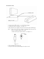
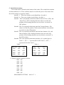
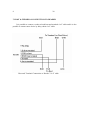
MR41XX Series
Magnetic Stripe card reader
RS-232 Interface
User‘s manual
INFORMATION
1. Decoder
For ISO 7811-4 or ANSI 3554 standard
MR4110 ( magnetic Card Track 1 version )
MR4120 ( magnetic Card Track 2 version )
MR4140 ( magnetic Card Track 2 version )
MR4130 ( magnetic Card Track 1 & Track 2 version )
MR4160 ( magnetic Card Track 2 & Track 3 version )
MR4170 ( magnetic Card Track 1 & Track 2 & Track 3 version )
Nun-ISO standard format
MR4220 ( magnetic reader for IBM passbook format version )
MR4240 ( magnetic reader for ISO 8484 format version )
MR4270 ( magnetic card reader Track 1 & 2 & 3 all alphanumeric format
version )
MR4280 ( magnetic card for JIS II standard format version )
MR4290 ( magnetic card for JIS I & JIS II format combined reader version )
2. Standard Package
Main Decoder Unit
3. Option
Power Supply Adaptor DC 12V / 120VAC
Power Supply Adaptor DC 12V / 220VAC
This device complies with Part 15 for the FCC
Rules. Operation is subject to the following two
condition : (1) This device may not cause harmful
interference. and (2) this device must accept any
interference received. including interference that
may cause undesired operation.
1. Introduction:
The model MR41XX series is magnetic stripe card reader with RS-232 interface
output. The product designed with the state-of-the-art microprocessor magnetic stripe
card reader technology, is totally compatible with the PC series port or any computer
with RS-232C interface input. The product is capable of reading data encoder on
magnetic cards that meet ANSI or ISO or for American driver license format ( AAMVA
/ CDL ) through the reader slot.
One block of switch settings is located on the reader bottom. This block of switch
settings is used to select RS-232 communication parameters and desired user protocol.
A two color LED indicators on the reader panel and a buzzer inside the reader
provide the operator with continuous status of the reader operations.
The major functions of MR4100 series reader are :
A. Baud Rate selectable.
B. Parity selectable.
C. STX / ETX selectable.
D. CR ( Carriage Return ) selectable.
E. Track 3 SS ( start sentinel character ) selectable.
F. Disable or enable the SS / ES selectable.
G. Two-way reading magnetic card.
H. Generates audible beep when reading is successful or error.
I. Power is supply by external power.
M. Supply adaptor DC 12V.
2. INSTALLATION
A. Basic conf iguration
1. DC power jack for +12V/DC power input.
2. RS-232 9 pin female connector: to be connected with the computer serial port.
3. The two color LED indicator is on the top portion , When card reader is power
ON, READY signal ( GREEN LED ) will be illuminated, the reader is ready to read .
The error signal ( RED LED ) will be illuminated when card reader error is encountered.
B. Install the reader
1. Setting function DIP switches. ( see switch block settings )
2. Connect the reader to computer. ( see Figure 2-2 )
3. Plug in the DC power adaptor to the power jack on the reader D-SUB 9 pin .
Note : 1. Make sure the DC power adaptor is unplugged from the power line
before you plug the adaptor to the reader.
2. Make sure the power input connector. ( see figure 2-3 )
Figure 2-3
4. Plug the adaptor to the power line.
5. the green LED will keep illuminating to be ready to a card.
C. Switch block settings.
The switch block is located on the bottom of the reader. The switch block contains
switches numbered 1-8. There switches must be set while the power off to ensure that
the switch settings are properly loaded.
Switch 1, 2 : There two switches set the Baud Rate. See table 1.
Switch 3, 4 : There two switches set the Parity. See table 2.
Switch 5 : This is an optional switch that sends the Start of Text ( STX ) and
End of Text ( ETX ) framing characters when set to the ON
positing. If the framing characters are not desire, set switch 5 to
OFF position.
Switch6 : This is an optional switch that sends the Carriage Return ( CR )
when set to the ON position. If this control character is not desired
set switch 6 to the OFF position.
Switch7 : This is an optional switch that sends the Start Sentinel ( SS ) and
End of Sentinel ( ES ) framing characters when set to the ON
position. If the framing characters are not desired, set switch 7 to
the OFF position.
Switch8 : This is an optional switch that sends the ( SS ) symbol type for
Track 3. ON “ + ” represent SS for ISO Track 3 , OFF “ ; ”
represent SS for ISO Track 3 .
Table1
Table 2
Baud Rate
1200
2400
4800
9600
SW1
OFF
ON
OFF
ON
SW2
OFF
OFF
ON
ON
Parity SW3
EVEN
ON
ODD
ON
SPACE OFF
MARK OFF
** Factory presets switches as below :
SW1 - ON
SW2 - ON
SW3 - ON
SW4 - OFF
SW5 - ON
SW6 - ON
SW7 - ON
SW8 - ON
PARATMENT SETTING : 9600 O 7 1
SW4
ON
OFF
ON
OFF
3. OPERATION
The two color LED will be keep green illuminating, if the installation is OK.
A. Status Indicators
There is a two color LED indicator on the panel to alert the operator .
There is also a buzzer inside the reader to provide an audio alert.
1. LED - Ready or Error indicator
The LED will keep the green color illuminating when the reader is ready to
read a magnetic stripe card. When an error detected a card the LED will
change to red color momentarily, after automatically change to green color
2. Buzzer
The buzzer will beep once when a magnetic card is read successfully, and 3
beeps when read error is deleted.
B. How to read a Magnetic Stripe Card
You may swipe a card though the reader slot, the LED go out momentarily when a
properly encoded card is swiped though the reader. The buzzer will beep once and
the LED will be light green color when all valid data are transmitted to computer
and the reader is ready to accept another card. when a card is not properly swiped
or can‘t be read, The buzzer will beeps third and LED will be light red color a
momentarily and turn to green color.
C. How to send the data to computer
All the data read by the reader will be send immediately to the computer though
the RS-232 cable. If the auto Carriage Return switch is enabled, a carriage return
character will be appended on each data.
The reader does no t need to receive commands from the host in order to transmit
data.
4. READER TO HOST MESSAGE FORMAT
A. Magnetic stripe card
Figure 4-1 shows, The data format transmitted after a card is read successfully. The
Track data is sent in the following order :
Figure 4-1
< STX >
SS
CARD
DATA
< CR >
ES
< ETX >
End of Text character
(03H) optional. set
SW5 to ON
Carriage Return Character ( 0DH )
Option
Set SW6 to ON
End Sentinel Character
( ASCII “?” ) optiona l
Set SW7 to ON
Card data in ASCII track order
Start Sentinel Character
( ASCII “ % ” for Track1 )
( ASCII “ ; ” for Track 2 )
( ASCII “ + ” for Track 3 ) ; Optional set SW8 to ON
Optional Set SW7 to ON
The ( ASCII “ ; ” for Track3 ) Optional set SW8 to OFF
Start of Text character ( 02H)
Optional. set SW5 to ON
5. TRANSMISSION DETAILS
Each ASCII character is transmitted with 1 start bit, 7 data bits, 1 parity and 1 stop
bit ( as shown below ). Logic levels conform to standard RS-232 levels ( i.e., data bits
are considered “ true ” or “ 1” if the level is low ).
1
2
Start
Bit
3
4
5
Data bits
6
7
P
Parity Stop
Bit
Bit
6. PIN ASSIGNMENT
MR4100 reader
9 P Female
1
2 ( TXD )
3 ( RXD )
4 ( DTR )
5 ( GND )
6 ( DSR )
7 ( RTS )
8 ( CTS )
9
To 25 PIN
Connector
NC
3
2
NC
7
NC
NC
NC
NC
Short connection
4
4
6
7
5
6
8
8
20
7. HOST & TERMINAL CONNECTION TO READER
It is possible to connect a reader to both host and terminal via Y cable and it is also
possible to connect next device by daisy chain via Y cable
Host and Terminal Connection to Reader Via Y cable
8. SPECIFICATIONS
A. Reference card standard : ANSI / ISO / JIS / CDL / AAMVA
B. Head Lifetime : Min. 500,000 passes
C. Speed
3-75 IPS at 75 BPI
3-75 IPS at 210 BPI
D. Power input
12VDC 300 mA
E. Connectors
1. RS-232 Output : 9 Pin D-sub Female
2. Power Input : + 12 VDC ( The power cable center is +12V )
F. Power Consumption :
MR4110,MR4120,MR4140 : 20 mA at 12VDC
MR4130,MR4160 : 30 mA at 12VDC
MR4170 : 40 mA at 12VDC
G.Environmental Requirement
Operating Temperature : 0 ℃ - 50℃
Operating Humidity : 30 - 95%