1
Agilent Technologies
U3040A Option S84
User’s and Service Guide
Mechanical Switching Test Set
Manufacturing Part Number: U3040-90001
Printed in USA June 2011
© Copyright Agilent Technologies, Inc. 2011
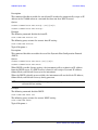
Warranty Statement
THE MATERIAL CONTAINED IN THIS DOCUMENT IS PROVIDED “AS IS,” AND IS SUBJECT
TO BEING CHANGED, WITHOUT NOTICE, IN FUTURE EDITIONS. FURTHER, TO THE
MAXIMUM EXTENT PERMITTED BY APPLICABLE LAW, AGILENT DISCLAIMS ALL
WARRANTIES, EITHER EXPRESS OR IMPLIED WITH REGARD TO THIS MANUAL AND
ANY INFORMATION CONTAINED HEREIN, INCLUDING BUT NOT LIMITED TO THE
IMPLIED WARRANTIES OF MERCHANTABILITY AND FITNESS FOR A PARTICULAR
PURPOSE. AGILENT SHALL NOT BE LIABLE FOR ERRORS OR FOR INCIDENTAL
OR CONSEQUENTIAL DAMAGES IN CONNECTION WITH THE FURNISHING, USE, OR
PERFORMANCE OF THIS DOCUMENT OR ANY INFORMATION CONTAINED HEREIN.
SHOULD AGILENT AND THE USER HAVE A SEPARATE WRITTEN AGREEMENT WITH
WARRANTY TERMS COVERING THE MATERIAL IN THIS DOCUMENT THAT CONFLICT
WITH THESE TERMS, THE WARRANTY TERMS IN THE SEPARATE AGREEMENT WILL
CONTROL.
DFARS/Restricted Rights Notice
If software is for use in the performance of a U.S. Government prime contract or
subcontract, Software is delivered and licensed as “Commercial computer software” as
defined in DFAR 252.227-7014 (June 1995), or as a “commercial item” as defined in FAR
2.101(a) or as “Restricted computer software” as defined in FAR 52.227-19 (June 1987) or
any equivalent agency regulation or contract clause. Use, duplication or disclosure of
Software is subject to Agilent Technologies’ standard commercial license terms, and
non-DOD Departments and Agencies of the U.S. Government will receive no greater than
Restricted Rights as defined in FAR 52.227-19(c)(1-2) (June 1987). U.S. Government users
will receive no greater than Limited Rights as defined in FAR 52.227-14 (June 1987) or
DFAR 252.227-7015 (b)(2) (November 1995), as applicable in any technical data.
ii
Safety Notes
The following safety notes are used throughout this document. Familiarize yourself with
each of these notes and its meaning before performing any of the procedures in this
document.
WARNING
Warning denotes a hazard. It calls attention to a procedure which,
if not correctly performed or adhered to, could result in injury or
loss of life. Do not proceed beyond a warning note until the
indicated conditions are fully understood and met.
CAUTION
Caution denotes a hazard. It calls attention to a procedure that, if not
correctly performed or adhered to, could result in damage to or destruction
of the product. Do not proceed beyond a caution sign until the indicated
conditions are fully understood and met.
Definitions
• Specifications describe the performance of parameters covered by the product warranty
(temperature –0 to 50 °C, unless otherwise noted.)
• Typical describes additional product performance information that is not covered by the
product warranty. It is performance beyond specification that 80% of the units exhibit
with a 95% confidence level over the temperature range 20 to 30 °C. Typical
performance does not include measurement uncertainty.
• Nominal values indicate expected performance or describe product performance that is
useful in the application of the product, but is not covered by the product warranty.
• Characteristic Performance describes performance parameter that the product is
expected to meet before it leaves the factory, but is not verified in the field and is not
covered by the product warranty. A characteristic includes the same guard bands as a
specification.
iii
iv
Contents
U3040A Option S84
Introduction . . . . . . . . . . . . . . . . . . . . . . . . . . . . . . . . . . . . . . . . . . . . . . . . . . . . . . . . . . . . . . . . . 2
Description . . . . . . . . . . . . . . . . . . . . . . . . . . . . . . . . . . . . . . . . . . . . . . . . . . . . . . . . . . . . . . . . . . 3
Verifying the Shipment . . . . . . . . . . . . . . . . . . . . . . . . . . . . . . . . . . . . . . . . . . . . . . . . . . . . . . . . 3
General Performance . . . . . . . . . . . . . . . . . . . . . . . . . . . . . . . . . . . . . . . . . . . . . . . . . . . . . . . . . . 4
Mounting Kits . . . . . . . . . . . . . . . . . . . . . . . . . . . . . . . . . . . . . . . . . . . . . . . . . . . . . . . . . . . . . . 4
Power Requirements . . . . . . . . . . . . . . . . . . . . . . . . . . . . . . . . . . . . . . . . . . . . . . . . . . . . . . . . 4
Environmental Requirements . . . . . . . . . . . . . . . . . . . . . . . . . . . . . . . . . . . . . . . . . . . . . . . . . 5
Environmental Tests . . . . . . . . . . . . . . . . . . . . . . . . . . . . . . . . . . . . . . . . . . . . . . . . . . . . . . . 5
Equipment Heating and Cooling . . . . . . . . . . . . . . . . . . . . . . . . . . . . . . . . . . . . . . . . . . . . . 5
Required Conditions for Accuracy Enhanced Measurement . . . . . . . . . . . . . . . . . . . . . . . 5
Dimensions and Space Requirements . . . . . . . . . . . . . . . . . . . . . . . . . . . . . . . . . . . . . . . . . 5
Front and Rear Panel Features . . . . . . . . . . . . . . . . . . . . . . . . . . . . . . . . . . . . . . . . . . . . . . . . . . 6
Specifications . . . . . . . . . . . . . . . . . . . . . . . . . . . . . . . . . . . . . . . . . . . . . . . . . . . . . . . . . . . . . . . . 9
Maximum Power Rating . . . . . . . . . . . . . . . . . . . . . . . . . . . . . . . . . . . . . . . . . . . . . . . . . . . . . . 9
Reference Conditions . . . . . . . . . . . . . . . . . . . . . . . . . . . . . . . . . . . . . . . . . . . . . . . . . . . . . . . . 9
Indicator Specifications . . . . . . . . . . . . . . . . . . . . . . . . . . . . . . . . . . . . . . . . . . . . . . . . . . . . . 10
Instrument Setup . . . . . . . . . . . . . . . . . . . . . . . . . . . . . . . . . . . . . . . . . . . . . . . . . . . . . . . . . . . . 12
LAN and GPIB Interface . . . . . . . . . . . . . . . . . . . . . . . . . . . . . . . . . . . . . . . . . . . . . . . . . . . . 12
Configuring the LAN Interface. . . . . . . . . . . . . . . . . . . . . . . . . . . . . . . . . . . . . . . . . . . . . . 12
Locating the Instrument. . . . . . . . . . . . . . . . . . . . . . . . . . . . . . . . . . . . . . . . . . . . . . . . . . . . . 13
Configuring the GPIB Interface . . . . . . . . . . . . . . . . . . . . . . . . . . . . . . . . . . . . . . . . . . . . . 14
Adding Instruments to the GPIB Configuration . . . . . . . . . . . . . . . . . . . . . . . . . . . . . . . . 14
Changing the GPIB Address. . . . . . . . . . . . . . . . . . . . . . . . . . . . . . . . . . . . . . . . . . . . . . . . 14
Controlling the Test Set . . . . . . . . . . . . . . . . . . . . . . . . . . . . . . . . . . . . . . . . . . . . . . . . . . . 15
Functional Tests . . . . . . . . . . . . . . . . . . . . . . . . . . . . . . . . . . . . . . . . . . . . . . . . . . . . . . . . . . . . . 25
Equipment Required . . . . . . . . . . . . . . . . . . . . . . . . . . . . . . . . . . . . . . . . . . . . . . . . . . . . . . . . 25
PNA-X Setup . . . . . . . . . . . . . . . . . . . . . . . . . . . . . . . . . . . . . . . . . . . . . . . . . . . . . . . . . . . . . 26
Transmission . . . . . . . . . . . . . . . . . . . . . . . . . . . . . . . . . . . . . . . . . . . . . . . . . . . . . . . . . . . . . 29
Service Information . . . . . . . . . . . . . . . . . . . . . . . . . . . . . . . . . . . . . . . . . . . . . . . . . . . . . . . . . . 31
Troubleshooting . . . . . . . . . . . . . . . . . . . . . . . . . . . . . . . . . . . . . . . . . . . . . . . . . . . . . . . . . . . 31
Troubleshooting the Power Supply. . . . . . . . . . . . . . . . . . . . . . . . . . . . . . . . . . . . . . . . . . . 31
Troubleshooting the Controller Board . . . . . . . . . . . . . . . . . . . . . . . . . . . . . . . . . . . . . . . . 31
Removing the Coaxial Switch . . . . . . . . . . . . . . . . . . . . . . . . . . . . . . . . . . . . . . . . . . . . . . . 33
Replaceable Parts . . . . . . . . . . . . . . . . . . . . . . . . . . . . . . . . . . . . . . . . . . . . . . . . . . . . . . . . . . 34
Safety and Regulatory Information . . . . . . . . . . . . . . . . . . . . . . . . . . . . . . . . . . . . . . . . . . . . . 35
Introduction. . . . . . . . . . . . . . . . . . . . . . . . . . . . . . . . . . . . . . . . . . . . . . . . . . . . . . . . . . . . . . . 35
Safety Earth Ground. . . . . . . . . . . . . . . . . . . . . . . . . . . . . . . . . . . . . . . . . . . . . . . . . . . . . . . . 35
Declaration of Conformity . . . . . . . . . . . . . . . . . . . . . . . . . . . . . . . . . . . . . . . . . . . . . . . . . . . 35
Statement of Compliance . . . . . . . . . . . . . . . . . . . . . . . . . . . . . . . . . . . . . . . . . . . . . . . . . . . . 35
Before Applying Power . . . . . . . . . . . . . . . . . . . . . . . . . . . . . . . . . . . . . . . . . . . . . . . . . . . . . . 36
Servicing . . . . . . . . . . . . . . . . . . . . . . . . . . . . . . . . . . . . . . . . . . . . . . . . . . . . . . . . . . . . . . . . . 37
Connector Care and Cleaning Precautions . . . . . . . . . . . . . . . . . . . . . . . . . . . . . . . . . . . . 37
Electrostatic Discharge Protection . . . . . . . . . . . . . . . . . . . . . . . . . . . . . . . . . . . . . . . . . . . . . . 38
Regulatory Information . . . . . . . . . . . . . . . . . . . . . . . . . . . . . . . . . . . . . . . . . . . . . . . . . . . . . . . 39
Instrument Markings . . . . . . . . . . . . . . . . . . . . . . . . . . . . . . . . . . . . . . . . . . . . . . . . . . . . . . . 39
Battery Collection . . . . . . . . . . . . . . . . . . . . . . . . . . . . . . . . . . . . . . . . . . . . . . . . . . . . . . . . . . 40
Compliance with German Noise Requirements . . . . . . . . . . . . . . . . . . . . . . . . . . . . . . . . . . 40
EMC Information . . . . . . . . . . . . . . . . . . . . . . . . . . . . . . . . . . . . . . . . . . . . . . . . . . . . . . . . . . 40
Agilent Support, Services, and Assistance . . . . . . . . . . . . . . . . . . . . . . . . . . . . . . . . . . . . . . . . 41
Service and Support Options . . . . . . . . . . . . . . . . . . . . . . . . . . . . . . . . . . . . . . . . . . . . . . . . . 41
Contacting Agilent . . . . . . . . . . . . . . . . . . . . . . . . . . . . . . . . . . . . . . . . . . . . . . . . . . . . . . . . . 41
Shipping Your Product to Agilent for Service or Repair . . . . . . . . . . . . . . . . . . . . . . . . . . . . 41
Contents-1
Contents
Contents-2
U3040A Option S84
User’s and Service Guide U3040-90001
1
U3040A Option S84
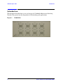
Introduction
Introduction
This document describes how to use and service the U3040AS84 Mechanical Switching
Test Set. The general use for this product is RF switching path applications.
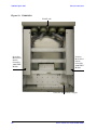
Figure 1
2
U3040AS84
User’s and Service Guide U3040-90001
U3040A Option S84
Description
Description
The Agilent U3040AS84 is a Mechanical Switching Test Set (DC to 40 GHz) based on the
L4491A RF Switch Platform. Eight individual 1x4 switches allow the user to select eight
input ports allowing the user to increase the DUT output to a full 32-Port network
analyzer solution.
The U3040AS84 can be used with the U3024AH10 and N5244A or N5245A. For further
information refer to the U3040AC01 Product Note for connection setup using the
U3024AH10 and the N5244A or N5245A.
The mechanical switches provide low insertion loss for the best dynamic range
performance, but have slower switching speed and limited life when compared to
solid-state switches. The operational frequency range of the extension test set is DC to
40 GHz.
The N5244/45A PNA-X Network Analyzer will be referred to throughout this document as
the PNA-X. The U3040AS84 will be referred to as the Test Set.
The U3040AS84 can only be controlled using an external GPIB controller or LAN.
When using Agilent IO libraries "Connection Expert Utility," the interface identifies the
Test Set as "U3040A" without Option S84. Option S84 will be listed on the serial tag on the
rear panel.
Verifying the Shipment
To verify the contents shipped with your product, refer to the “Box Content List” included
with the shipment.
Inspect the shipping container. If the container or packing material is damaged, it should
be kept until the contents of the shipment have been checked mechanically and electrically.
If there is physical damage refer to “Contacting Agilent” on page 41. Keep the damaged
shipping materials (if any) for inspection by the carrier and an Agilent Technologies
representative.
User’s and Service Guide U3040-90001
3
U3040A Option S84
General Performance
General Performance
The U3040AS84 specifications have been leveraged from the 87104D Multiport
Electromechanical Switch.
It is not intended to specify as an overall level system performance. A functional certificate
is supplied for the U3040AS84.
There are no internal adjustment in the U3040AS84, therefore an annual calibration is not
required.
CAUTION
Refer to the standard instrument documentation for damage limits to the
ports. Verify that your test setup will not cause those limits to be exceeded.
Mounting Kits
The Test Set available options:
• U3040AC01-002 Connects the U3040AS84 to the U3024AH10, includes cables and
locking feet for two U3040AS84’s (U3040-60002).
• U3040AS84-1CP Rack Mount Kit with Handles (5063-9222)
• U3040AS84-1CM Rack Mount Kit without Handles (5063-9215)
• U3040AS84-1CN Front Handle Kit (5063-9228)
Power Requirements
Verify that the required ac power is available at all necessary locations before installing
the Test Set to the PNA.
• 100/120/220/240 V (50/60 Hz)
• The instruments can operate with mains supply voltage fluctuations up to ± 10% of the
nominal voltage.
• Air conditioning equipment (or other motor–operated equipment) should not be placed
on the same ac line that powers the Test Set.
CAUTION
4
This product has an autoranging line voltage input. Be sure the supply
voltage is within the specified range.
User’s and Service Guide U3040-90001
U3040A Option S84
General Performance
Environmental Requirements
Refer to the PNA-X standard documentation for environmental requirements.
Environmental Tests
The U3040AS84 complies with all applicable safety and regulatory requirements for the
intended location of use.
Operating Environment
• Operating Ambient: Temperature 0 to 55 °C
• The instrument can safely operate in a relative humidity of 80% for temperatures to
31 degrees C, decreasing linearly to 50% relative humidity at 40 degrees C.
Equipment Heating and Cooling
If necessary, install air conditioning and heating to maintain the ambient temperature
within the appropriate range. Air conditioning capacity must be consistent with the rating
listed in the PNA standard documentation.
CAUTION
When installing this product in a cabinet, the convection into and out of the
product must not be restricted. The ambient temperature (outside the
cabinet) must be less than the maximum operating temperature of the
product by 4°C for every 100 watts dissipated in the cabinet. If the total
power dissipated in the cabinet is greater than 800 watts, then forced
convection must be used.
Required Conditions for Accuracy Enhanced Measurement
Accuracy–enhanced (error–corrected) measurements require the ambient temperature of
the PNA-X and Test Set to be maintained within ± 1 °C of the ambient temperature at
calibration.
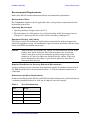
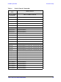
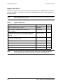
Dimensions and Space Requirements
Standard installation of the Test Set and PNA-X includes configuration and installation on
a customer provided lab bench or table top of adequate size and strength.
Table 1
Item
Test Set Dimensions
Weight
Width
42.5 cm (16.73 in)
Depth
58 cm (22.83 in)
Height
17.78 cm (7in)
Weight
9 kg (19.84 lb)
User’s and Service Guide U3040-90001
5
U3040A Option S84
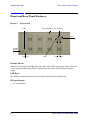
Front and Rear Panel Features
Front and Rear Panel Features
Figure 2
Front Panel
LEDs
RF Input/Outputs (x8) Switch In
Port 3
Standby
Switch
LAN Reset
Port 2
Port 1 Port 4
Standby Switch
Note that this switch is Standby only, not a line switch. The main power cord can be used
as the system disconnecting device. It disconnects the mains circuits from the mains
supply.
LAN Reset
The LAN reset button restores the instrument's default LAN configuration.
RF Input/Output
• 8 (1 x 4) Switches
6
User’s and Service Guide U3040-90001
U3040A Option S84
Front and Rear Panel Features
Instrument State LEDs
When the power is applied to the U3040AS84, the instrument enters its power-on
sequence which requires several seconds to complete. The LEDs provide information on
the state of the instrument during power-on and during upgrades of the instrument
firmware. Table 2 identifies the instrument states based on the color and functioning of the
LEDs.
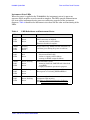
Table 2
LED
LED Definitions and Instrument States
Color
Instrument State
ATTN
LAN
PWR
Off
Green
Green
Instrument in “ready” state
LAN connection established
- instrument has an IP address
Firmware download complete
ATTN
LAN
PWR
flashing
flashing
Green
Power-on/boot-up. ATTN and LAN will flash red
and then green during the power-on self-test.
ATTN
LAN
PWR
Off
Red
Green
No LAN connection due to:
- disconnected LAN cable
- failure to acquire and IP address
- waiting for DHCP-assigned address
ATTN
LAN
PWR
Green (flashing
Green
Green
Instrument Busy State
- firmware download (LAN LED red if download
over GPIB)
- lengthy instrument operation in progress
ATTN
LAN
PWR
Red (flashing
Green
Green
Instrument programming error or self-test error.
Error queue is read using SYSTem:ERRor?
ATTN
LAN
PWR
Off
Green (flashing)
Green
Instrument identification. Activated from
instrument Web interface:
ON: Turn on Front Panel Interface Indicator
OFF: Turn off Front Panel Interface Indicator
User’s and Service Guide U3040-90001
7
U3040A Option S84
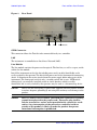
Figure 3
Front and Rear Panel Features
Rear Panel
GPIB
LAN
Line Module
GPIB Connector
This connector allows the Test Set to be connected directly to a controller.
LAN
The instrument is controlled over Local Area Network (LAN).
Line Module
The line module contains the power cord receptacle. The line fuse, as well as a spare, reside
within the line module.
Install the instrument so that the detachable power cord is readily identifiable and is
easily reached by the operator. The detachable power cord is the instrument disconnecting
device. It disconnects the mains circuits from the mains supply before other parts of the
instrument. The front panel switch is only a standby switch and is not a LINE switch.
Alternatively, an externally installed switch or circuit breaker (which is readily
identifiable and is easily reached by the operator) may be used as a disconnecting device.
CAUTION
Always use the three-prong ac power cord supplied with this product. Failure
to ensure adequate grounding by not using this cord may cause damage to the
product.
WARNING
This is a Safety Class I Product (provided with a protective earthing
ground incorporated in the power cord). The mains plug shall be
only be inserted in a socket outlet provided with a protective earth
contact. Any interruption of the protective conductor inside or
outside of the product is likely to make the product dangerous.
Intentional interruption is prohibited.
8
User’s and Service Guide U3040-90001
U3040A Option S84
Specifications
Specifications
Specifications described in this document are provided from the 87104D Operation and
Service manual (87104-90001). Refer to the 87104D documentation on agilent.com for
complete product performance and specifications.
Supplemental and typical characteristics are intended to provide typical information, but
not warranted performance parameters.
Maximum Power Rating
Into internal termination:
• 1 W CW
• 50 W peak, 10us max pulse width, not to exceed 1 W average
Into thru path:
• Hot switching: 2 W CW
• 100W peak, 10us max pulse width, not to exceed 2 W average
Reference Conditions
Power Handling at 25° C is 100 W at 4 GHz.
Into internal termination:
• Cold switching only (no hot switching)
• Ambient temperature of 75 °C or less
• Sea level, 0.88 derating at 15,000 ft.
• Load VSWR < 1.2 (see graph for derating above 1.2 VSWR
Figure 4
Maximum Incident CW Power (cold switching) vs. Frequency
User’s and Service Guide U3040-90001
9
U3040A Option S84
Specifications
Indicator Specifications
Into internal termination:
• Maximum withstand voltage: 60 V
• Maximum current capacity: 150 mA
• Maximum “ON” resistance: 2.5 Ω
• Maximum “OFF” resistance: 10 G Ω
Figure 5
Power Derating Factor versus VSWR
Table 3
U3040A S85
Frequency Range
DC to 40 GHz
Insertion Loss Figure 6 on page 11
0.3 dB + 0.015 x frequency (GHz), DC to 26.5 GHz
0.030 x frequency (GHz) – 0.1 dB, 26.5 to 40 GHz
Isolation
Figure 7 on page 11
80 dB minimum, 12 to 15 GHz
70 dB minimum, 15 to 20 GHz
65 dB minimum, 20 to 40 GHz
SWR
1.3 maximum, DC to 4 GHz
1.35 maximum, 4 to 12.4 GHz
1.5 maximum,12.4 to 18 GHz
1.7 maximum, 18 to 26.5 GHz
1.95 maximum, 26.5 to 40 GHz
Repeatability (Up to 5 million
cycles measured at 25°C)
0.03 dB maximum
Connectors
2.92 (f)
10
User’s and Service Guide U3040-90001
U3040A Option S84
Figure 6
Insertion Loss vs Frequency
Figure 7
Isolation Loss vs Frequency
User’s and Service Guide U3040-90001
Specifications
11
U3040A Option S84
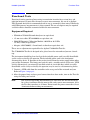
Instrument Setup
Instrument Setup
LAN and GPIB Interface
This section contains information for configuring the U3040A LAN and GPIB interfaces
using Agilent IO Libraries “Connection Expert Utility”.
Configuring the LAN Interface
1. Connect the Test Set to the PC.
2. Turn On the Test Set.
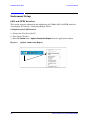
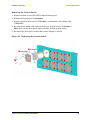
3. Select IO Control icon > Agilent Connection Expert from the application window.
Figure 8
12
Agilent Connection Expert
User’s and Service Guide U3040-90001
U3040A Option S84
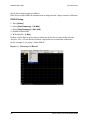
Instrument Setup
Locating the Instrument
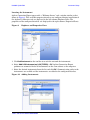
Agilent Connection Expert opens with a “Welcome Screen,” and a window similar to that
shown in Figure 8. The available computer interfaces are configured during installation of
the Agilent IO Libraries and are displayed in the left column (Explorer Pane). The
properties of the configured interface are displayed in the right column (Propertied Pane).
Figure 9
Explorer and Properties Pane
1. Click Add Instrument on the tool bar to search the network for instruments.
2. Select Add LAN Instrument on LAN (TCPIP0) > OK. Agilent Connection Expert
performs an automatic find of all instruments on the same subnet as the computer.
3. Select the desired instruments from the list and click OK. Communication paths to the
instruments are verified and the instruments are added to the configured interface.
Figure 10
Adding Instruments
User’s and Service Guide U3040-90001
13
U3040A Option S84
Instrument Setup
Configuring the GPIB Interface
Programming access to the Test Set is also available through the instrument's GPIB
interface. The GPIB connector is located on the rear panel of the instrument.
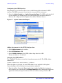
1. Select the Agilent Control icon > Agilent Connection Expert. If a GPIB card is installed
in your computer, the GPIB interface was configured during installation of the IO
libraries and is displayed in the Explorer Pane of the “Welcome” Screen.
Figure 11
Agilent Connection Expert
Adding Instruments to the GPIB Configuration
1. Select Add Instrument on the tool bar.
2. Select GPIB Interface > OK.
3. Select U3040A’s Address in the GPIB address drop-down list > OK.
Factory set address = 12 (default)
Changing the GPIB Address
The U3040A GPIB address can only be changed programmatically. The GPIB address
command is:
SYSTem:COMMunicate:GPIB:ADDRess <address>
When the address is changed, the new GPIB address is not updated in the Agilent
Connection Expert if the instrument was previously configured.
1. From the Agilent Connection Expert application window, highlight the instrument
that's address was changed and click Change Properties in the Configurable Properties
application window, change the address to the new address setting and select OK.
14
User’s and Service Guide U3040-90001
U3040A Option S84
Instrument Setup
Controlling the Test Set
Agilent U3040A is a “slave” instruments. A controller must be used to control the Test Set.
There are two methods that can be used to control the Test Set.
• Using LAN connection
• Using GPIB connection
Once the connection between the Controller and the Test Set has been established (LAN or
GPIB), the Test Set can be controlled using SCPI commands.
Reset Command
This command resets the instrument.
Syntax
*RST
Remote Interface Configuration
LAN Configuration Commands
Description
This command assigns a static Internet Protocol (IP) address for the U3040A. Contact your
network administrator for the valid IP address to use for your instrument.
NOTE
If you change the IP address, you must cycle power on the U3040A to activate
the new address.
Syntax
SYSTem:COMMunicate:LAN:IPADdress <address>
SYSTem:COMMunicate:LAN:IPADdress?
You can also queries the U3040A for the IP address it was assigned to.
Example
The following command sets the IP address:
SYST:COMM:IPAD 169.254.149.35
The following query returns the IP address currently being used by the instrument (quotes
are also returned).
SYST:COMM:LAN:IPAD?
Typical Response: "169.254.149.35"
User’s and Service Guide U3040-90001
15
U3040A Option S84
Instrument Setup
Description
This command disable or enable the use of Auto-IP standard to automatically assign an IP
address to the U3040A when on a network that does not have DHCP servers.
Syntax
SYSTem:COMMunicate:LAN:AUTOip {OFF|0|ON|1}
SYSTem:COMMunicate:LAN:AUTOip?
Example
The following command disable the Auto-IP:
SYST:COMM:LAN:AUTOIP OFF
The following query returns the current Auto-IP setting:
SYST:COMM:LAN:AUTOIP?
Typical Response: 0
Description
This command disables or enables the use of the Dynamic Host Configuration Protocol
(DHCP).
Syntax
SYSTem:COMMunicate:LAN:DHCP {OFF|0|ON|1}
SYSTem:COMMunicate:LAN:DHCP?
When DHCP is enable (factory setting), the instrument will try to obtain an IP address
from the DHCP server. If a DHCP server is found, it will assign a Dynamic IP address,
Subnet Mask, and Default Gateway to the instrument.
When the DHCP is disable or unavailable, the instrument will use the Static IP address,
Subnet Mask, and Default Gateway during power-on.
NOTE
If you change the DHCP setting, you must cycle power on the U3040A to
activate the new setting.
Example
The following command disables DHCP:
SYST:COMM:LAN:DHCP OFF
The following query returns the current DHCP setting:
SYST:COMM:LAN:DHCP?
Typical Response: 0
16
User’s and Service Guide U3040-90001
U3040A Option S84
Instrument Setup
Description
This command assigns the IP address of the Domain Name System (DNS) server. Contact
your network administrator to determine if DNS is being used and for the correct address.
Syntax
SYSTem:COMMunicate:LAN:DNS <address>
SYSTem:COMMunicate:LAN:DNS?
NOTE
If you change the DNS address, you must cycle power on the U3040A to
activate the new address.
Example
The following command sets the DNS address:
SYST:COMM:LAN:DNS 198.105.232.4
The following query returns the DNS address currently being used by the instrument (the
quotes are also returned).
SYST:COMM:LAN:DNS?
Typical Response: "198.105.232.4"
Description
This command assigns a Domain Name to the U3040A. The Domain Name is translated
into an IP address.
Syntax
SYSTem:COMMunicate:LAN:DOMain "<name>"
SYSTem:COMMunicate:LAN:DOMain?
NOTE
If you change the Domain Name, you must cycle power on the U3040A to
activate the new address.
Example
The following command defines the Domain Name:
SYST:COMM:LAN:DOM www.agilent.com
The following query returns the Domain Name currently being used by the instrument:
SYST:COMM:LAN:DOM?
Typical response: www.agilent.com
User’s and Service Guide U3040-90001
17
U3040A Option S84
Instrument Setup
Description
This command assigns a Default Gateway for the U3040A. The specified IP Address sets
the Default Gateway which allows the instrument to communicate with systems that are
not on the local subnet. Thus, this is the Default Gateway where packets are sent which
are destined for a device not on the local subnet, as determined by the Subnet Mask
setting. Contact your network administrator to determine if a gateway is being used and
for the correct address.
Syntax
SYSTem:COMMunicate:LAN:GATEway <address>
SYSTem:COMMunicate:LAN:GATEway?
Example
The following command sets the Default Gateway address:
SYST:COMM:LAN:GATEWAY 255.255.20.11
The following query returns the Default Gateway address currently being used by the
instrument (the quotes are also returned).
SYST:COMM:LAN:GATEWAY?
Typical Response: "255.255.20.11"
Description
This command assigns a Host Name to the U3040A. The Host Name is the host portion of
the domain name, which is translated into an IP address.
Syntax
SYSTem:COMMunicate:LAN:HOSTname "<name>"
SYSTem:COMMunicate:LAN:HOSTname?
NOTE
If you change the Domain Name, you must cycle power on the U3040A to
activate the new address.
Example
The following command defines a Host Name:
SYST:COMM:LAN:HOST "LAB1-L4491A"
The following query returns the Host Name currently being used by the instrument
(the quotes are also returned):
SYST:COMM:LAN:HOST?
Typical Response: "LAB1-L4491A"
18
User’s and Service Guide U3040-90001
U3040A Option S84
Instrument Setup
GPIB Configuration Commends
Description
This command assigns a GPIB address to the U3040A.
Syntax
SYSTem:COMMunicate:GPIB:ADDRess <address>
SYSTem:COMMunicate:GPIB:ADDRess?
NOTE
If you change the GPIB address, you must cycle power on the U3040A to
activate the new address.
Example
The following command sets the GPIB address to 10:
SYST:COMM:GPIB:ADDR 10
The following query returns the current GPIB address:
SYST:COMM:GPIB:ADDR?
Typical Response: 10
User’s and Service Guide U3040-90001
19
U3040A Option S84
Instrument Setup
Controlling Test Set Switch Settings
Description
This command executes the specified factory defined sequence from the non-volatile
memory. If the specified sequence name not currently stored in the memory, due to
corrupted program or accidentally deleted, an error will be generated.
Syntax
ROUTe:SEQuence:TRIGger <command>
Parameters
Refer to Table 4 for commands used to control the Test Set’s programmable attenuator.
Table 4
Switch Control Commands
Definition
Name
SCPI Command
Top Level SCPI
Commands
2nd Level SCPI Commands
Switch1_Port1
:ROUT:CLOS(@1162);
Switch1_Port2
:ROUT:CLOS(@1163);
Switch1_Port3
:ROUT:CLOS(@1165);
Switch1_Port4
:ROUT:CLOS(@1166);
Switch2_Port1
:ROUT:CLOS(@1142);
Switch2_Port2
:ROUT:CLOS(@1143);
Switch2_Port3
:ROUT:CLOS(@1145);
Switch2_Port4
:ROUT:CLOS(@1146);
Switch3_Port1
:ROUT:CLOS(@1252);
Switch3_Port2
:ROUT:CLOS(@1253);
Switch3_Port3
:ROUT:CLOS(@1255);
Switch3_Port4
:ROUT:CLOS(@1256);
Switch4_Port1
:ROUT:CLOS(@1272);
Switch4_Port2
:ROUT:CLOS(@1273);
Switch4_Port3
:ROUT:CLOS(@1275);
Switch4_Port4
:ROUT:CLOS(@1276);
Switch5_Port1
:ROUT:CLOS(@1172);
Switch5_Port2
:ROUT:CLOS(@1173);
Switch5_Port3
:ROUT:CLOS(@1175);
20
User’s and Service Guide U3040-90001
U3040A Option S84
Table 4
Instrument Setup
Switch Control Commands
Definition
Name
SCPI Command
Top Level SCPI
Commands
2nd Level SCPI Commands
Switch5_Port4
:ROUT:CLOS(@1176);
Switch6_Port1
:ROUT:CLOS(@1152);
Switch6_Port2
:ROUT:CLOS(@1153);
Switch6_Port3
:ROUT:CLOS(@1155);
Switch6_Port4
:ROUT:CLOS(@1156);
Switch7_Port1
:ROUT:CLOS(@1242);
Switch7_Port2
:ROUT:CLOS(@1243);
Switch7_Port3
:ROUT:CLOS(@1245);
Switch7_Port4
:ROUT:CLOS(@1246);
Switch8_Port1
:ROUT:CLOS(@1262);
Switch8_Port2
:ROUT:CLOS(@1263);
Switch8_Port3
:ROUT:CLOS(@1265);
Switch8_Port4
:ROUT:CLOS(@1266);
Port1_All
:ROUT:CLOS(@1142,1152,1162,1172,1142,1252,1262,1272);
Port2_All
:ROUT:CLOS(@1143,1153,1163,1173, 1243,1253,1263,1273);
Port3_All
:ROUT:CLOS(@1145,1155,1165,1175, 1245,1255,1265,1275);
Port4_All
:ROUT:CLOS(@1146,1156,1166,1176, 1246,1256,1266,1276);
Open_All
:ROUT:CLOS(@1147,1157,1167,1177, 1247,1257,1267,1277);
Open_Switch1
:ROUT:CLOS(@1167);
Open_Switch2
:ROUT:CLOS(@1147);
Open_Switch3
:ROUT:CLOS(@1257);
Open_Switch4
:ROUT:CLOS(@1277);
Open_Switch5
:ROUT:CLOS(@1177);
Open_Switch6
:ROUT:CLOS(@1157);
Open_Switch7
:ROUT:CLOS(@1247);
Open_Switch8
:ROUT:CLOS(@1267);
User’s and Service Guide U3040-90001
21
U3040A Option S84
NOTE
Instrument Setup
For a complete list of SCPI commands refer to Agilent L449xA RF Switch
Platform User’s Guide (L4490-90001).
Example
The following SCPI command “Switch1_Port1” selects Switch number 1 and the output
Port number 1.
ROUT:SEQ:TRIG Switch1_Port1
NOTE
PNA-X interface controller user command reference to GPIB address Syntax
as prefix followed by command. Example: 12 ":ROUT:SEQ:TRIG Port1_All"
In the system configuration the two U3040AS84 instruments must have
different GPIB addresses. ROUTe:SEQuence:TRIGger <command>
A wait statement is recommended for every switch command.
22
User’s and Service Guide U3040-90001
U3040A Option S84
Instrument Setup
Theory of Operation
This section provides a general description of the U3040AS84 Mechanical Switching Test
Set. This is followed by a more detailed operating theory. The operation of each group is
described briefly to the assembly level only. Detailed component level circuit theory is not
provided. The Test Set consists of four main components: a controller module, 39495EXT
module, distribution board for mechanical switching and eight 1 x 4 coaxial switches.
Figure 12 illustrates the components and interconnects of the Switching Test Set.
Block Diagram for the U3040AS84 Test Set
PORT1
PORT2
PORT3
3
PORT4
SW1 IN
5
6
PORT1
C
PORT2
2
PORT3
3
PORT4
SW2 IN
2
5
6
Figure 12
LAN
GPIB
LAN
C
Cntrl Bus
P101
P102
Exp Bus
Port 1
P102
Bank 4
P101
Bank 3
P102
34945EXT
Switch / Attenuator Driver
(Master - Left)
Bank 2
P101
Y1151A
P102
Y1151A
P101
SW4
Exp Bus
Port 2
Bank 4
5
L4491A w/Opt 002
Bank 3
Y1151A
34945EXT
Switch / Attenuator Driver
(Slave - Right)
EXT IN
+ 24VDC
Y1151A
3
SW8
2
SW6
C
PORT3
SW3
6
PORT2
SW7
5
PORT1
SW5
3
PORT4
SW5 IN
SW1
SW5
2
PORT3
SW6
C
PORT2
SW2
6
PORT1
AC IN
Bank 1
5
PORT4
SW4 IN
I/O
3
PORT3
NOTE: ALL Switch port connectors are female K-Type (2.92mm).
2
PORT2
SW4
C
PORT1
ATTN
+ 24VDC
6
PORT4
Controller Module
and Power Supply
34989-66503 KOM
TO 34945EXT (Slave)
5
PORT3
SW3 IN
Front Panel
PWR
SW1
87104D
024, 161
SW2
3
PORT2
SW3
2
PORT1
6
5
PORT3
6
PORT4
3
C
SW8 IN
2
PORT2
PORT3
C
PORT1
PORT2
User’s and Service Guide U3040-90001
6
PORT4
5
SW7 IN
3
PORT1
rp 062411
2
SW8
C
SW7
PORT4
SW6 IN
23
U3040A Option S84
Instrument Setup
Controller Module
Inside the controller module there are two main components, the AC-DC power supply and
controller board. The AC-DC power supply is a 12V/65W power supply that is converted to
various voltages by means of DC-DC converter inside the module. It provides regulated
voltages to all assemblies in the Test Set as well as following voltages to drive
programmable step attenuator in the Test Set. The internal DC voltage has the following
specification:
• +24V/0.6A
• +12V/3A fuse
• +5V/1A
The controller board is the “brain” of the Test Set, it handles all the communication
between the Controller and the Test Set via LAN or GPIB connectivity. Refer to
“Controlling the Test Set” on page 15.
39495EXT Module
There are two external module drives (primary and secondary) that control the eight
mechanical switches. The mechanical switch are connected to the Test Set through the
distribution board (Y1151A), which is installed on the 34945EXT module.
The 34945EXT is divided into four banks, organized by channel number. Any distribution
board may be installed in any bank, and multiple distribution boards of the same type may
be installed on the same 34495EXT module.
Distribution Board
The distribution board provides an interface between the 34945EXT module and the
programmable step attenuator. Depending on the model number and attenuator, a suitable
distribution board will be use.
24
User’s and Service Guide U3040-90001
U3040A Option S84
Functional Tests
Functional Tests
Functional testing consists of measuring transmission insertion loss, return loss, and
isolation between all ports. For the most accurate measurements, the use of an Agilent
PNA Network Analyzer is recommended and its use is assumed in these notes. Familiarity
with RF/microwave measurements is also assumed. The use of adapters may be required
and their effects should be accounted within the measurements.
Equipment Required
• N5242A or N5244A Network Analyzer (or equivalent)
• 3.5 mm test cables (E7342-60004) or equivalent (x2)
• N4691B Electronic Calibration Module (300 kHz to 26.5 GHz)
3.5 mm, 2-Port or equivalent
• Adapter (85027-60005) 3.5 mm female to female or equivalent (x2)
There are no adjustments required for the Agilent U3040AS84 Test Set.
The U3040AS84 Test Set is designed to be placed near the network analyzer on a bench
top.
The instrument should be placed so that the detachable power cord is readily identifiable
and is easily reached by the operator. The detachable power cord is the instrument
disconnecting device. It disconnects the mains circuits from the mains supply before other
parts of the instrument. The front panel switch is only a standby switch and is not a LINE
switch. Alternatively, an externally installed switch or circuit breaker (which is readily
identifiable and is easily reached by the operator) may be used as a disconnecting device.
1. Connect a GPIB cable from the controller to the rear panel of the network analyzer.
Refer to Figure 3 on page 8.
2. After the proper front and rear panel connections have been made, turn on the Test Set
using the front panel switch.
NOTE
For accurate repeatable measurements, be sure to let the Test Set warm up
for at least two hours. For the most stable and accurate measurements, leave
the Test Set turned on at all times. Do not touch the power sensor for at least
30 minutes before making measurements.
User’s and Service Guide U3040-90001
25
U3040A Option S84
Functional Tests
Set up the network analyzer as follows:
Refer to the standard PNA-X documentation or help menu for adapter removal calibration.
PNA-X Setup
1. Press [Preset].
2. Select [Start Frequency] > [10 MHz]
3. Select [Stop Frequency] > [26.5 GHz]
4. Number of Points 201.
5. IF Bandwidth > [1 kHz]
Perform a full 2-Port adapter removal calibration at the two test ports of the network
analyzer. (Use a 3.5 mm female-to-female adaptor for the transmission calibration).
In this example we are using a 2-Port PNA-X.
Figure 13
26
Selecting Cal Wizard
User’s and Service Guide U3040-90001
U3040A Option S84
Figure 14
ECal Module
Figure 15
Adapter Removal Cal
User’s and Service Guide U3040-90001
Functional Tests
27
U3040A Option S84
Figure 16
28
Functional Tests
Connecting the Test Set to the Network Analyzer
User’s and Service Guide U3040-90001
U3040A Option S84
Functional Tests
Transmission
1. Connect the cable attached to PORT 1 of the network analyzer to Switch number 1
"Switch IN" on the Test Set.
2. Connect the cable from PORT 2 of the network analyzer to Switch number 1 "Port 1" on
the Test Set.
3. Set up the Test Set to select Switch number 1 and Port number 1 with the following
command over GPIB or LAN:
ROUT:SEQ:TRIG Switch1_Port1
For complete information on controlling the Test Set, refer to “Controlling the Test Set”
on page 15.
4. Set up the network analyzer to measure S21.
5. Verify the performance. Refer to Table 6 on page 11.
6. Save data file as a .CSV for future data performance analysis.
Figure 17
Saving Data
User’s and Service Guide U3040-90001
29
U3040A Option S84
Figure 18
Functional Tests
Selecting CSV File
7. Set up the Test Set to select different switches and ports. Table 4 on page 20. Execute
the following command over the GPIB:
ROUT:SEQ:TRIG SwitchX_PortY (X = 1/2/3/4/5/6/7/8, Y = 1/2/3/4)
8. Repeat step 1 through step 7 for all switches.
9. Verify the isolation, match, etcetera for all the switches and ports, using the .CSV files.
30
User’s and Service Guide U3040-90001
U3040A Option S84
Service Information
Service Information
There are many other repair and calibration options available from the Agilent
Technologies support organization. The options cover a range of service agreements with
varying response times. Contact Agilent for additional information on available service
agreements for this product.
WARNING
These servicing instructions are for use by qualified personnel only.
To avoid electrical shock, do not perform any servicing unless you
are qualified to do so.
Troubleshooting
This section contains information for troubleshooting the Test Set to the assembly level
only. By following these procedures, you may determine if the power supply, front panel, or
main switch board needs replacing. Refer to Figure 12, “Block Diagram for the U3040AS84
Test Set,” as an aid in troubleshooting.
NOTE
Refer to the L4491A Service manual for lower level component replacement.
NOTE
If you need to disassemble the instrument, be sure to work at an antistatic
workstation and use a grounded wrist strap to prevent damage from
electrostatic discharge (ESD). See Figure 21 on page 38.
Troubleshooting the Power Supply
Turn the instrument on. Verify the condition of the LED on the front panel:
1. Check the cable and connections between the main board and front panel board.
2. If the cable and connections are working and the LED is still off, there is still a
possibility that the power supply is not supplying the necessary +24 V, +12 V, and +5 V
to the main board.
Disconnect the dc power cable from the power supply to the main switch board and
measure the voltages. They should be +24 V, +12 V, and +5 V. If not, replace the power
supply.
Troubleshooting the Controller Board
Turn the instrument power on and verify the following:
1. Check the LED display for the model/option and revision information; if there is no
backlite or horizontal/vertical lines are missing, verify that the power supply is working
properly, if so replace the LED display.
2. If there is no information or the information is scrambled, replace the controller board.
3. Verify the switching paths by issuing commands to switch each of the paths. Ensure
that the LED indicates the appropriate path.
User’s and Service Guide U3040-90001
31
U3040A Option S84
Figure 19
Service Information
U3040AS84
Switch (x8)
Secondary
Mechanical
Switch
Controller
39495 EXT
Module
Primary
Mechanical
Switch
Controller
39495 EXT
Module
Controller Module/Power Supply
32
User’s and Service Guide U3040-90001
U3040A Option S84
Service Information
Removing the Coaxial Switch
1. Remove the four screws (0515-0772) from the front panel.
2. Remove the dress panel (U3040-00004).
3. Remove the old coaxial switch (87104-60043) and disconnect the ribbon cable
(87050-6055).
4. Re-connect the ribbon cable and install the new coaxial switch (87104-60043).
Note: Port 1 of the dress panel aligns with Port 2 of the coaxial switch.
5. Re-install the dress panel and the four screws (Torque to 9 in-lb).
Figure 20
Replacing the Coaxial Switch
User’s and Service Guide U3040-90001
33
U3040A Option S84
Service Information
Replaceable Parts
The following table contains the list of replaceable parts for the U3040AS84. If any of these
parts or assemblies are replaced, you must run all performance tests to verify conformance
to specifications.
NOTE
Special options are built to order, long lead times may be encountered when
ordering replacement parts.
Table 5
Replaceable Parts
Replacement Part
Part Number
Qty
Cable assembly multi bias connect
87050-6055
8
Replacement for 40 GHz SP4T, terminated,
Option 161-024
87104-60043
8
4U RF Switch platform with integrated switch driver,
includes 64 switch drive lines with Options STD, 005,
002, 004
L4491A-CFG004
1
Extender Driver for 34945A, 1 required for each 64
coils with standard option.
34945EXT-CFG001
1
PCA, front panel
34989-66502
1
Assembly, controller box for L4490A and L4491A
L4490-60001
1
1 x 4 Switch dress panel
U3040-20004
8
PCA, UW Distribution card
Y1153-66501
4
NOTE
34
Before replacing an assembly or board, inspect the assembly for obvious,
easily repaired defects such as bent pins on ICs or cold solder joints.
User’s and Service Guide U3040-90001
U3040A Option S84
Safety and Regulatory Information
Safety and Regulatory Information
Introduction
Review this product and related documentation to familiarize yourself with safety
markings and instructions before you operate the instrument. The documentation contains
information and warnings that must be followed by the user to ensure safe operation and
to maintain the product in a safe condition.
Safety Earth Ground
WARNING
This is a Safety Class I product (provided with a protective earthing ground
incorporated in the power cord). The mains plug shall be inserted only into
a socket outlet provided with a protective earth contact. Any interruption
of the protective conductor, inside or outside the product is likely to make
the product dangerous. Intentional interruption is prohibited.
CAUTION
Always use the three prong AC power cord supplied with this product. Failure
to ensure adequate earth grounding by not using this cord may cause product
damage and the risk of electrical shock.
Declaration of Conformity
A copy of the Declaration of Conformity is available upon request, or a copy is available on
the Agilent Technologies web site at
http://regulations.corporate.agilent.com/DoC/search.htm
Statement of Compliance
This instrument has been designed and tested in accordance with CAN/CSA 22.2
No. 61010-1-04, UL Std. 61010-1 (2nd Edition), and IEC 61010-1 (Second Edition).
User’s and Service Guide U3040-90001
35
U3040A Option S84
Safety and Regulatory Information
Before Applying Power
Verify that the premises electrical supply is within the range of the instrument. The
instrument has an autoranging power supply.
WARNING
If this product is not used as specified, the protection provided by the
equipment could be impaired. This product must be used in a normal
condition (in which all means for protection are intact) only.
CAUTION
The Mains wiring and connectors shall be compatible with the connector used
in the premise electrical system. Failure, to ensure adequate earth grounding
by not using the correct components may cause product damage, and serious
injury.
CAUTION
This product is designed for use in Installation Category II and Pollution
Degree 2.
CAUTION
Verify that the premise electrical voltage supply is within the range specified
on the instrument.
CAUTION
Ventilation Requirements: When installing the instrument in a cabinet,
the convection into and out of the instrument must not be restricted. The
ambient temperature (outside the cabinet) must be less than the maximum
operating temperature of the instrument by 4 °C for every 100 watts
dissipated in the cabinet. If the total power dissipated in the cabinet is
greater than 800 watts, forced convection must be used.
36
User’s and Service Guide U3040-90001
U3040A Option S84
Safety and Regulatory Information
Servicing
WARNING
Danger of explosion if battery is incorrectly replaced. Replace only
with the same or equivalent type recommended. Discard used
batteries according to manufacturer’s instructions.
WARNING
Always turn the instrument power off before removing or installing
an assembly.
WARNING
These servicing instructions are for use by qualified personnel only.
To avoid electrical shock, do not perform any servicing unless you
are qualified to do so.
WARNING
The opening of covers or removal of parts is likely to expose the user to
dangerous voltages. Disconnect the instrument from all voltage sources
before opening.
WARNING
No operator serviceable parts inside. Refer servicing to qualified personnel.
To prevent electrical shock, do not remove covers.
WARNING
The detachable power cord is the instrument disconnecting device. It
disconnects the mains circuits from the mains supply before other parts of
the instrument. The front panel switch is only a standby switch and is not a
LINE switch (disconnecting device).
Connector Care and Cleaning Precautions
Remove the power cord to the instrument. To clean the connectors use alcohol in a well
ventilated area. Allow all residual alcohol moisture to evaporate, and fumes to dissipate
prior to energizing the instrument.
WARNING
To prevent electrical shock, disconnect the Agilent Technologies U3040A
Option S84 from mains electrical supply before cleaning. Use a dry cloth or
one slightly dampened with water to clean the external case parts. Do not
attempt to clean internally.
WARNING
If flammable cleaning materials are used, the material shall not be stored,
or left open in the area of the equipment. Adequate ventilation shall be
assured to prevent the combustion of fumes, or vapors.
User’s and Service Guide U3040-90001
37
U3040A Option S84
Electrostatic Discharge Protection
Electrostatic Discharge Protection
Protection against electrostatic discharge (ESD) is essential while removing assemblies
from or connecting cables to the instrument. Static electricity can build up on your body
and can easily damage sensitive internal circuit elements when discharged. Static
discharges too small to be felt can cause permanent damage. To prevent damage to the
instrument:
• always have a grounded, conductive table mat in front of your test equipment.
• always wear a grounded wrist strap with grounding cord, connected to a grounded
conductive table mat, having a 1 MΩ resistor in series with it, when handling
components and assemblies or when making connections.
• always wear a heel strap (9300-1126) when working in an area with a conductive floor.
If you are uncertain about the conductivity of your floor, wear a heel strap.
• always ground yourself before you clean, inspect, or make a connection to a
static-sensitive device or test port. You can, for example, grasp the grounded outer shell
of the test port or cable connector briefly.
• always ground the center conductor of a test cable before making a connection to the
analyzer test port or other static-sensitive device. This can be done as follows:
1. Connect a short to one end of the cable to short the center conductor to the outer
conductor.
2. While wearing a grounded wrist strap, grasp the outer shell of the cable connector.
3. Connect the other end of the cable to the test port and remove the short from the
cable.
Figure 21
38
ESD Protection Setup
User’s and Service Guide U3040-90001
U3040A Option S84
Regulatory Information
Regulatory Information
This section contains information that is required by various government regulatory
agencies.
Instrument Markings
The instruction documentation symbol. The product is marked with this symbol
when it is necessary for the user to refer to the instructions in the documentation.
This symbol indicates separate collection for electrical and electronic equipment,
mandated under EU law as of August 13, 2005. All electric and electronic equipment
are required to be separated from normal waste for disposal (Reference WEEE
Directive, 2002/96/EC).
This symbol indicates that the power line switch is in the STANDBY position.
This symbol is used to identify a terminal which is internally connected to the
product frame or chassis.
The CE mark is a registered trademark of the European Community. (If accompanied
by a year, it is when the design was proven.)
The CSA mark is a registered trademark of the CSA International. This instrument
complies with Canada: CSA 22.2 No. 61010-1-04.
This is a symbol of an Industrial Scientific and Medical Group 1 Class A product
(CISPR 11, Clause 54)
ICES/NMB-001
IP 2 0
This is a marking to indicate product compliance with the Canadian
Interference-Causing Equipment Standard (ICES-001).
The instrument has been designed to meet the requirements of IP 2 0 for egress and
operational environment.
This is a required mark signifying compliance with an EMC requirement. The C-Tick
mark is a registered trademark of the Australian Spectrum Management Agency.
China RoHS regulations include requirements related to packaging, and require
compliance to China standard GB18455-2001.
This symbol indicates compliance with the China RoHS regulations for
paper/fiberboard packaging.
User’s and Service Guide U3040-90001
39
U3040A Option S84
Regulatory Information
Battery Collection
Do not throw batteries away but collect as small chemical waste, or in accordance with
your country’s requirements. You may return the battery to Agilent Technologies for
disposal. Refer to “Contacting Agilent” on page 41 for assistance.
Compliance with German Noise Requirements
This is to declare that this instrument is in conformance with the German Regulation on
Noise Declaration for Machines (Laermangabe nach der Maschinenlaermrerordnung-3.
GSGV Deutschland).
Acoustic Noise Emission/Geraeuschemission
LpA<70 dB
Lpa<70 dB
Operator Position
am Arbeitsplatz
Normal Operation
normaler Betrieb
per ISO 7779
nach DIN 45635 t. 19
EMC Information
Complies with European EMC Directive 2004/108/EC
• IEC/EN 61326-1
• CISPR Pub 11 Group 1, class A
• AS/NZS CISPR 11
• This ISM device complies with Canadian ICES-001.
Cet appareil ISM est conforme a la norme NMB du Canada.
40
User’s and Service Guide U3040-90001
U3040A Option S84
Agilent Support, Services, and Assistance
Agilent Support, Services, and Assistance
Service and Support Options
The standard product warranty is a one-year return to Agilent Technologies service
warranty.
NOTE
There are many other repair and calibration options available from the
Agilent Technologies support organization. These options cover a range of
service agreements with varying response times. Contact Agilent for
additional information on available service agreements for this product.
Contacting Agilent
Assistance with test and measurements needs and information or finding a local Agilent
office are available on the Web at:
http://www.agilent.com/find/assist
If you do not have access to the Internet, contact your field engineer.
NOTE
In any correspondence or telephone conversation, refer to the Agilent product
by its model number and full serial number. With this information, the
Agilent representative can determine the warranty status of your unit.
Shipping Your Product to Agilent for Service or Repair
IMPORTANT
Agilent Technologies reserves the right to reformat or replace the internal
hard disk drive in your analyzer as part of its repair. This will erase all user
information stored on the hard disk. It is imperative, therefore, that you
make a backup copy of your critical test data located on the analyzer’s hard
disk before shipping it to Agilent for repair.
If you wish to send your instrument to Agilent Technologies for service or repair:
• Include a complete description of the service requested or of the failure and a
description of any failed test and any error message.
• Remove and retain the front handles and all rack mount hardware. The analyzer should
be sent to Agilent in the same configuration as it was originally shipped.
• Ship the analyzer using the original or comparable antistatic packaging materials.
• Contact Agilent for instructions on where to ship your analyzer.
User’s and Service Guide U3040-90001
41
U3040A Option S84
42
Agilent Support, Services, and Assistance
User’s and Service Guide U3040-90001