1
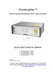
AX10432 User’s Manual
I.
!"
II.
z Fully compatible with IBM VGA
z Displays flat panel and CRT
monitor simultaneously
z Onboard built-in 1MB VGA RAM
z Supports panel resolutions of
1024 x 768 (mono), 800 x 600
(Hi-color), and 640 x 480 (Hicolor)
III.
z Supports non-interlaced CRT
monitors with resolutions of
up to 1024 x 768-256 colors
z Hi-color display capability
with flat panels and CRT
monitors up to 800 x 600
resolution
z Direct interface to Color and
Monochrome Dual Drive and
Single Drive panels
¾ BIOS Customization Utility
¾ Power Management
¾ Panel Switching Utility
(including service code)
¾ BIOS Update Utility
Utility
#$#%&''$()*
"+, $."/0/
#%&'"
IV.
¾ Windows 3.1
¾ Windows 95
¾ Windows 98
V.
¾ Windows NT3.51
¾ Windows NT4.0
9AX10432 PC/104 Module x 1
9Driver & Utility diskette x 2
9CRT connection adapter x 1
9Screws (3mm) x 4
9Bronze stiandoff (6mm) x 4
9User’s manual x 1
%*
",
"
©Copyright 2000 AXIOM Technology Co., Ltd.
Version A1 October 2000
Printed in Taiwan
AX10432 User’s Manual
VI.
43
44
3
1
2
1
VII.
1
2
1
2
15
16
B1
2
1
A1
C1
64
63
40
39
BIOS MODE
JP1 Setting
WRITE-ENABLE
WRITE-PROTECT(default)
Short 1-2
Short 2-3
VIII. !"#$
Pin
1
4
7
10
13
16
Signal
Red
N/A
N/A
AGND
N/A
N/A
Pin
2
5
8
11
14
Signal
AGND
Blue
N/A
GND
Vertical Sync
Pin
3
6
9
12
15
Signal
Green
AGND
GND
Horizontal Sync
N/A
©Copyright 2000 AXIOM Technology Co., Ltd.
Version A1 October 2000
Printed in Taiwan
AX10432 User’s Manual
%
!"#$
Pin
1
4
7
10
13
16
19
22
25
28
31
34
37
40
43
Description
Pin
2
5
8
11
14
17
20
23
26
29
32
35
38
41
44
N/A
GND
ENAVEE
P1
P4
P7
P10
P13
P16
P19
P22
GND
M
ENABKL
VDDM
Description
Pin
3
6
9
12
15
18
21
24
27
30
33
36
39
42
+12VM
VDDM
GND
P2
P5
P8
P11
P14
P17
P20
P23
SHFCLK
LP
GND
VDDM
Description
GND
VDDM
P0
P3
P6
P9
P12
P15
P18
P21
GND
FLM
GND
-SHFCLK
! !
Name
P0~P23
ENABKL
SHFCLK
M
LP
FLM
+12VM
ENAVEE
VDDM
IX.
CN1
Pin
No.
35
38
36
37
9
10
11
12
13
14
15
16
17
Description
Flat panel data output
Activity Indicator and Enable Backlight outputs
Shift clock. Pixel clock for flat panel data
M signal for panel AC drive control
Latch pulse. Flat panel equivalent of HSYNC
First line marker. Flat panel equivalent of VSYNC
+12V power controlled by chipset
Power sequencing controls for panel LCD bias volt
5V
Mono
LCD
Color LCD
Color
LCD*
Color LCD Color LCD
Pin Name Dual-scan Single-scan Dual-scan Dual-scan
SHFCLK
LP
FLM
M
P0
P1
P2
P3
P4
P5
P6
P7
P8
STN
8-bit
SCLK
LCLK
FLM
MDL
UD3
UD2
UD1
UD0
LD3
LD2
LD1
LD0
STN
16-bit
CL2
CL1
FLM
M
SUD7
SUD6
SUD5
SUD4
SUD3
SUD2
SUD1
SUD0
SLD7
STN
8-bit
CL2
CL1
FLM
M
SUD7
SUD6
SUD5
SUD4
SUD3
SUD2
SUD1
SUD0
STN
16-bit
CL2
CL1
FLM
M
SUD7
SUD6
SUD5
SUD4
SLD7
SLD6
SLD5
SLD4
SUD3
Color
LCD
Gray
Gray
TFT
TFT
PLASM
EL
9/12/16-bit
DCLK
LP/HS
FLM/VS
DE
B0
B1
B2
B3
B4
G0
G1
G2
G3
18/24-bit
DCLK
LP/HS
FLM/VS
DE
B0
B1
B2
B3
B4
B5
B6
B7
G0
8-bit
CLK
HSYNC
VSYNC
DISPTMG
8-bit
VCLK
HS
VS
DE
OD3
OD3
Continued . . . . .
©Copyright 2000 AXIOM Technology Co., Ltd.
Version A1 October 2000
Printed in Taiwan
AX10432 User’s Manual
CN1
Pin
No.
18
19
20
21
22
23
24
25
26
27
28
29
30
31
32
Mono
LCD
Color LCD
Color
LCD*
Color LCD Color LCD
Color
LCD
Gray
TFT
TFT
PLASM
EL
9/12/16-bit
G4
G5
R0
R1
R2
R3
R4
18/24-bit
G1
G2
G3
G4
G5
G6
G7
R0
R1
R2
R3
R4
R5
R6
R7
8-bit
OD2
OD1
OD0
ED3
ED2
ED1
ED0
8-bit
OD2
OD1
OD0
ED3
ED2
ED1
ED0
Pin Name Dual-scan Single-scan Dual-scan Dual-scan
STN
8-bit
STN
16-bit
SLD6
SLD5
SLD4
SLD3
SLD2
SLD1
SLD0
P9
P10
P11
P12
P13
P14
P15
P16
P17
P18
P19
P20
P21
P22
P23
STN
8-bit
STN
16-bit
SUD2
SUD1
SUD0
SLD3
SLD2
SLD1
SLD0
Gray
X.
!"#$%
10&)#%&' 23343!&)"'
*53678"33* 78#%&'"9!4
3!&)//0"'
-9!0*/04
3!&)"'-
*/
43!&)":
1) UNLOCK
2) NEWVGA
[press enter]
[filename]
[press enter]
536#%&':
!"##
$""%%
& ' (
CAUTION:
(1) This utility, in run-time, will be using the memory
range C000:8000 to C000:FFFF. Please avoid this
memory range.
(2) Please make sure that the JP1 is short to 2-3 in
normal mode.
©Copyright 2000 AXIOM Technology Co., Ltd.
Version A1 October 2000
Printed in Taiwan