1
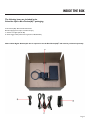
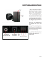
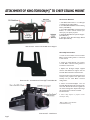
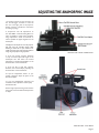
KINO-TORSION(M)™
USER MANUAL
CONTENTS
Welcome . . . . . . . . . . . . . . . . . . . . . . . . . . . . . . . . . . . . . . . . . . . . . . . . . . . . . . . . . . . . . . . . Page 1
Inside the Box . . . . . . . . . . . . . . . . . . . . . . . . . . . . . . . . . . . . . . . . . . . . . . . . . . . . . . . . . . Page 2
Attachment of Lens to Kino-Torsion(M)™ Mechanism . . . . . . . . . Page 3
Electrical Connections . . . . . . . . . . . . . . . . . . . . . . . . . . . . . . . . . . . . . . . . . . . . . . . . Page 4
Attachment of Kino-Torsion(M)™ to Chief Ceiling Mount . . . . Page 5
Adjusting the Anamorphic Image . . . . . . . . . . . . . . . . . . . . . . . . . . . . . . . . . . . . Page 6
About Schneider . . . . . . . . . . . . . . . . . . . . . . . . . . . . . . . . . . . . . . . . . . . . . . . . . . . . . . Back Cover
WELCOME
Congratulations on your purchase of a Schneider Optics, Inc. Kino-Torsion(M)™ anamorphic system. This system is composed of the finest
optical and mechanical components available. The Cine-Digitar Anamorphic lens is of commercial grade and should last indefinitely provided
that it is used within reasonable parameters of temperature and shock. The mechanical assemblies within the Kino-Torsion(M)™ lens mover
are designed for the demanding duty cycle of a professional screening room.
Installation by a qualified professional is recommended for best results.
Page 1
INSIDE THE BOX
The following items are included in the
Schneider Optics Kino-Torsion(M)™ packaging:
A. Kino-Torsion(M)™ Motorized Lens Mechanism
B. Power Supply (12-volt output, 110-240-volt input)
C. 3 Power Cord Types (US, UK, EU)
D. 12-Volt Trigger Cable (3.5mm Phono Type, Mono, 3M, Male-Male)
Note: A Cine-Digitar Anamorphic lens is required to use the Kino-Torsion(M)™ and must be purchased seperately.
Page 2
ATTACHMENT OF LENS TO KINO-TORSION(M)™ MECHANISM
Tools Needed:
1. Allen Wrench: 1/16”, 1/8”
2. Ball End Allen Wrench: 4mm
(Important for Mounting Bolts)
Assembly Instructions:
1. Remove Kino-Torsion(M)™ mechanism
and Cine Digitar anamorphic lens, if
purchased together, from packaging. Inspect
all components for damage that may have
occurred during shipping.
2. Insert lens into the frame of the KinoTorsion(M).™ See Illustration #1
Illustration #1 - Rear View of Kino-Torsion(M)™ with Lens Installed
3. Align the lens, rotating it until the flat sides
of the inner bezel are vertical. See Illustration #2
4. Tighten the thumb screw to lock lens in
place. See Illustration #1
Illustration #2 -Front View of Kino-Torsion(M)™
Page 3
ELECTRICAL CONNECTIONS
1. Select the appropriate power cord (US, UK,
EU) for your location, and connect the power
supply to the Kino-Torsion(M)™ and electrical
outlet. A green LED should go on if power is
working correctly. A flashing LED indicates
that power is not correct. See Illustration #4.
2. When the Kino-Torsion(M)™ receives 12
volts through this connector, the lens moves
out of the projector view. When the voltage
is zero, the lens moves back into projector
view. A 12-volt trigger must be supplied by a
programmable 12-volt source on the projector,
video scaler, or home theater control system. A
3 meter trigger cable is provided.
Illustration #3 -Electrical Connection Area
3. Test Kino-Torsion(M)™by triggering unit and
observe motion. Trigger <ON> should move
lens away. Trigger <OFF> restores original
position.
4. As an alternative or local testing, the KinoTorsion(M)™ can also be controlled via simple
contact closure without a 12-volt trigger. Use a
wire to connect terminal 1 to 2. This will move
lens out of the projector view when connected,
similar to using the 12-volt trigger.
5. To gain access to the terminal block, the
motor cover needs to be removed. Unscrew
the motor cover screws with 1/16” allen
wrench, and carefully pull back cover.
See Illustration #3.
Illustration #4 -Detail of Electrical Connection Area
Page 4
ATTACHMENT OF KINO-TORSION(M)TM TO CHIEF CEILING MOUNT
Accessories Needed:
1. Chief MFG, CMS Column, or 1.5” NPT pipe
of suitable Length. (Chief CMS™)
2. Chief MFG, RPA LCD/DLP Universal Ceiling
Mount. (Chief RPA™)
3. Chief MFG, SLBU/SLMU Universal Interface
Bracket, or custom interface bracket (not
shown) for your specific projector.
4. Chief MFG, PAN-2 Panamorph Lens Support.
(Chief PAN-2™)
5. Schneider Optics, Kino-Torsion(M) / PAN-2
Bracket (#54-018712).
Illustration #5 - Detail of Chief PAN-2 Lens Support
Assembly Instructions:
1. Install the Chief CMS™ Column and Chief
RPA™ Universal Ceiling Mount as instructed
in Chief manual.
2. Attach the Chief PAN-2™ lens support
to Chief RPA™ Universal Ceiling Mount as
instructed in Chief manual.
3. Replace the 90-degree adapter supplied
with the Chief PAN-2 lens support with the
Schneider PAN-2 bracket. See Illustration #5.
Illustration #6 - Schneider Kino-Torsion(M)™ PAN-2 Bracket
4. Mount projector interface bracket (universal/
custom) to the projector. Then place entire
assembly into the Chief RPA™ Universal
Ceiling Mount.
5. Mount the Kino-Torsion(M)™ onto the
Schneider PAN-2 bracket with the mating holes.
Use a 5/32” ball end allen wrench to tighten the
two 10-32 mounting bolts. Adjust knobs to align
the vertical position of the lens if needed.
See Illustration #7.
6. Mount safety lanyard to projector mount
securely for safety.
“RPA” and “PAN-2” are trademarks
of Chief Manufacturing.
Illustration #7 - Chief Mount
Page 5
ADJUSTING THE ANAMORPHIC IMAGE
1. If focusing projector for the first time, use
the 12-volt trigger controller to take the
lens out of the light path of the projector.
Follow projector manufacture instructions
for setting up image.
2. <Important> Use the adjustments on
the Chief RPA™ Universal Ceiling Mount as
much as possible to center image. Projector
image adjustments should be centered as
mush as possible for proper alignment to the
anamorphic.
3. Deploy the anamorphic lens into the projector
light path using the controller (Trigger OFF),
checking to assure that no part of the lens or
cradle contacts any part of the projector. Observe
image using the projector test grid pattern.
Illustration #8 - Detail of Chief Mount
4. If you see vertical “vignette” distortion
on top or bottom, adjust the height of the
anamorphic lens. Use either the vertical
adjustments on the Kino-Torsion(M)™ or the
knurled knobs on the Chief Mount.
5. If you see left or right side “vignette”
distortion, shift horizontally by adjusting the
knurled knobs on the Chief Mount.
6. If you see “trapezoidal”, “barrel”, or “pincushion” distortion, adjust the pitch on the
Kino-Torsion(M).™
7. If you see “parallelogram” distortion and
stretched corners, adjust lens rotation (roll).
See Illustration #2.
8. If the image requires focusing, loosen the lens
focus knob on the Schneider Anamorphic lens
to adjust.
Illustration #9 - Front Detail
Page 6
ABOUT SCHNEIDER
Schneider Optics is the U.S. subsidiary
of the world-renowned German optical
manufacturer, Schneider-Kreuznach. Schneider
has been producing the highest quality optics
on the market for over 90 years, offering
solutions for large-format photography, photo
enlarging, motion picture projection, optical
filtration, and industrial applications. In 2000,
Schneider Optics acquired Century Precision
Optics, adding its over 50 years experience
manufacturing superior attachments for film
and video.
The factory is fully compliant with ISO 9001
standards. Its U.S. subsidiary, Schneider Optics,
was founded in 1972.
Schneider Optics has offices in Hauppauge, NY
and Van Nuys, CA and a network of hundreds
of dealers around the globe, ready to assist you
with any of your imaging needs.
Seperately the two companies were leaders
in their respective spheres of the optical
world—both having been awarded Technical
Achievement Awards from the Academy of
Motion Picture Arts and Sciences (Schneider
in 2005, 2001, 1978 and 1976; Century
in 1992). Together they are the ultimate
solution to all your optical needs.
Joseph Schneider founded the company in
1913 in Bad Kreuznach, Germany. Since that
time the Schneider factory has been constantly
modernized, always remaining state-of-the-art.
Century Optics first opened its doors
in North Hollywood, CA in 1948, and
quickly gained a reputation for expert lens
repair, custom modification and intelligent
innovation. In the early 80’s Century
began creating what has become the most
extensive array of ultra-high quality video
lens accessories available anywhere.
Schneider Optics, Inc.
7701 Haskell Avenue
Van Nuys, CA 91406
Phone: +1 818 766-3715 • +1 800 228-1254
Fax: 818 505-9865
Email: [email protected]
www.schneideroptics.com
Schneider Cinema Projection Lens technology has
won four Technical Achievement Awards from the
Academy of Motion Picture Arts and Sciences
Jos. Schneider Optische Werke GmbH
Business Unit: Cinema
Ringstr. 132 • D-55543 Bad Kreuznach
Phone: ++49-(0)671-60 12 82
Fax: ++49-(0)671-60 11 08
Email: [email protected]
www.schneiderkreuznach.com
9010-0075
Rev 1.01