1
USER MANUAL
SP91
THERMAL PRINTER
The contents of this document are subject to change without notice
CAUTIONS
�It’s grade A product,maybe it cause wireless jammer in the environment. In
such circumstances, need the user to do related steps.
COPYRIGHT
�Copied date: 2013
�Version:1.5
目 录
1
2
3
4
5
GENERAL DESCRIPTION.............................................................................................1
1.1 Basic Specifications..................................................................................................1
1.2 Printable Area........................................................................................................... 1
1.3 Internal Buffer........................................................................................................... 2
1.4 Printing Position and Tear off Position..................................................................... 2
CONFIGURATION AND INSTALLATION...................................................................... 4
2.1 Interface Specifications............................................................................................ 4
2.1.1 RS232 Serial Interface...................................................................................4
2.1.2 IEEE 1284 Bidirectional Parallel Interface.................................................... 7
2.1.3 Ethernet Interface......................................................................................... 11
2.1.4 USB Interface............................................................................................... 12
2.2 Printer Installation................................................................................................... 12
2.2 Power Connector.............................................................................................12
2.3 Drawer Connector...................................................................................................13
FUNCTIONS................................................................................................................. 14
3.1 List of Commands................................................................................................... 14
3.2 Power Button and Buttons......................................................................................16
3.2.1 Power Button................................................................................................ 16
3.2.2 Panel Button................................................................................................. 16
3.3 DIP Switch...............................................................................................................16
3.3.1 DIP Switch 1................................................................................................. 17
3.3.2 DIP Switch 2................................................................................................. 18
3.4 LED/Alarm...............................................................................................................18
3.5 Roll Paper Cover.....................................................................................................19
3.6 Self-test................................................................................................................ 19
3.9 Error Processing.................................................................................................. 20
3.9.1 Error Type............................................................................................... 20
3.9.2 Printer Operation When an Error Occurs...............................................20
3.10 Status Conditions............................................................................................... 20
3.11 Buffer-Full Printing................................................................................................ 21
CASE SPECIFICATIONS............................................................................................. 22
4.1 External Dimensions and Mass..............................................................................22
4.2 Color........................................................................................................................22
4.3 External Appearance.............................................................................................. 22
COMMANDS.................................................................................................................23
5.1 Command Notation.................................................................................................23
5.2 Explanation of Terms.............................................................................................. 23
5.3 Detailed Explanation of Commands.......................................................................24
HT...........................................................................................................................24
LF........................................................................................................................... 24
CR.......................................................................................................................... 25
DLE EOT n.............................................................................................................25
-
-
3
DLE ENQ n............................................................................................................ 27
ESC S0.................................................................................................................. 28
ESC DC4............................................................................................................... 28
ESC ! n...................................................................................................................28
ESC $ nL nH.......................................................................................................... 29
ESC % n................................................................................................................ 29
ESC & y c1 c2 [x1 d1...d(y × x1)]...[xk d1...d(y ×xk)]............................................30
ESC * m nL nH d1... dk......................................................................................... 32
ESC 2.....................................................................................................................34
ESC 3 n..................................................................................................................34
ESC ? n..................................................................................................................34
ESC @................................................................................................................... 35
ESC a n..................................................................................................................35
ESC D n1 . . . nk NUL........................................................................................... 35
ESC i...................................................................................................................... 36
ESC J n.................................................................................................................. 36
ESC m....................................................................................................................37
ESC \ nL nH........................................................................................................... 37
ESC c 3 n...............................................................................................................37
ESC c 4 n...............................................................................................................38
ESC c 5 n...............................................................................................................38
ESC d n..................................................................................................................39
ESC t n...................................................................................................................39
FS p n m................................................................................................................ 39
ESC P m n1 n2...................................................................................................... 40
FS q n [xL xH yL yH d1...dk]1...[xL xH yL yH d1...dk]n........................................ 41
FS p n m................................................................................................................ 43
GS ! n..................................................................................................................... 44
GS * x y d1..d( x y 8 )............................................................................................ 45
GS / m.................................................................................................................... 46
GS :.....................................................................................................................46
GS H n................................................................................................................... 47
GS I n..................................................................................................................... 47
GS L nL nH............................................................................................................ 48
①GS V m ②GS V m n.......................................................................................... 49
GS W nL nH...........................................................................................................49
GS ^ r t m............................................................................................................... 50
GS f n..................................................................................................................... 51
GS h n.................................................................................................................... 51
①GS k m d1 . dk NUL ②GS k m n d1 . dn.......................................................... 51
GS r n.....................................................................................................................55
GS v 0 m xL xH yL yH d1 ... dk............................................................................. 56
GS w n................................................................................................................... 57
GS ( k PL PH cn fn n1 n2(cn=49 ,fn=65)..............................................................57
-
-
4
GS ( k pL pH cn fn n1 n2(cn=49 ,fn=69)...............................................................58
GS ( k pL pH cn fn m d1.......dk(cn=49 ,fn=80).....................................................58
GS ( k pL pH cn fn m (cn=49 ,fn=81)....................................................................59
GS ( k pL pH cn fn m (cn=49 ,fn=82)....................................................................59
5.5 Chinese Character Control Command...................................................................59
FS ! n......................................................................................................................60
FS &....................................................................................................................... 60
FS ..........................................................................................................................61
FS W n................................................................................................................... 61
APPENDIX A: MISCELLANEOUS NOTES......................................................................... 61
APPENDIX B: ROLL PAPER SETUP..................................................................................62
APPENDIX C:GET RIGHT FROM AUTOCUTTER ERROR............................................62
APPENDIX D: CLEAN THE PRINT HEAD..........................................................................62
APPENDIX E: CODE128 BAR CODE.................................................................................63
-
-
5
SP91 User Manual
1
GENERAL DESCRIPTION
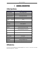
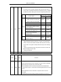
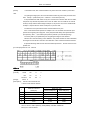
1.1 Basic Specifications
Specifications
Printing Method
Parameter
Line Thermal Printer
Printing Speed
Printing Density
Printing Directions
150mm/S(Max)
8dot/mm
Feed Paper Directions
Printing Width
Max diameter
79±0.5mm
83mm
Printing
effective
width
Paper Solve Method
Line Width
72mm
Full cut/Partial cut
3.75MM
Print head
Thermal Print Head
Auto cutter
Interface
Character
Print character each
line
Print character each
line
Emulation
Power Supply
During Operation
During Storage
Dimension
Weight
Support OS
Seiko CADP347
100KM
700,000 times
Serial/Parallel/Ethernet/USB
ASCII/GB18030 Simplified Chinese /Traditional
Chinese/Multinational Chinese
24/48 21/42 16/58
48/48 42/42 32/58
ESC/POS® standard command protocol
DC24V/2A
0℃~50℃ 0~85%(humidity)
-20℃~60℃ 0~85%(humidity)
142×154×144(W×L×H)
1300g(no paper roll)
XP/2000/2003/Win7/Win 8
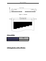
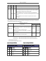
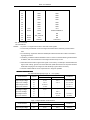
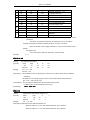
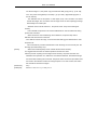
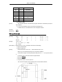
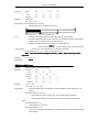
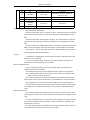
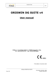
1.2 Printable Area
79.5±0.5mm The printable area of thermal paper is 72.2 ± 0.2 mm,There are 4.0 mm blank
area left and right side,as follows:
.
SP91 User Manual
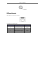
1.3 Internal Buffer
Receive Date Buffer Memory
4KB
Macro Defined Buffer Memory
NV Bit Image Buffer Memory
2KB
192KB
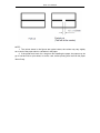
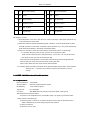
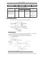
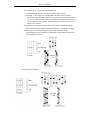
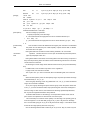
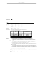
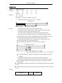
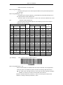
1.4 Printing Position and Tear off Position
SP91 User Manual
NOTE:
1.The values shown in the figures are typical values, the values may vary slightly
as a result of the paper slack or variations in the paper.
2.If the printer don’t work for a long time but installing the paper, the paper may be
go to bad and fall on print head; In such a case, before printing that must be fed paper
30mm firstly.
SP91 User Manual
2
CONFIGURATION AND INSTALLATION
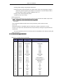
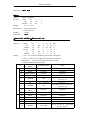
2.1 Interface Specifications
2.1.1 RS232 Serial Interface
2.1.1.1 Specifications
Data Transmission: Serial
Synchronization:
Handshaking:
Asynchronous
RTS/CTS or DTR/DSR or XON/XOFF control
Signal Levels: MARK = -3 to -15 V;
Logic “1”/ OFF
SPACE = +3 to +15 V;
Baud Rate:
115200、38400、19200、9600bps
Data Word Length:
Parity:
Logic “0”/ ON
8 bits
None
Stop Bits: 1 bit or more
Connector (the side on the printer ):
NOTE:
D-SUB25 male
Handshaking,Baud rate and Parity decided by DIP Switch 1 setting.(refer to 3.3.1)
the stop bits fixed on 1.
Switching between online and offline:
The printer have not the online and offline switch.
The printer goes offline:
1) Between when the power is turned on (includes reset using the interface)
and when the printer
is get ready to receive the data.
2) During the self-test.
3) When the cover is open.
4) During paper feeding pushing the paper feed button.
5) Stop printing when out of paper.
6) During macro executing standby status.
7) When an error have occurred.
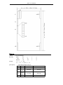
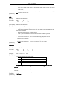
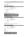
2.1.1.2 Interface Pin Signal Definition
Interface connector terminal assignments and signal functions description as the following table:
Signal assignments and functions
Pin
Signal
Signal
NO.
Name
Direction
2
RXD
Input
Receive data
3
TXD
Output
Receive data
Function
SP91 User Manual
1)
When DTR/DSR control is selected,The signal indicates whether
the printer is busy. SPACE indicates that the printer get ready to
receive data,but MARK indicates that the printer is busy. Changing
the Memory Switch setting to be used as a signal for printer busy.
2)
Memory SW1-3 Status
Printer Status
ON
OFF
BUSY
BUSY
BUSY
BUSY
—
BUSY
—
BUSY
—
BUSY
—
BUSY
—
BUSY
BUSY
BUSY
1.During the period from when the
power is turned on to when the
printer is ready to receive data.
2. During the self-test.
3. When the cover is open.
Offlin
4
RTS
e
Outpu
4. During paper feeding using the
paper feed button.
5. When the printer stops
t
printingdue to a paper-end.
6. During macro executing
standby status.
7. When an error has occurred.
8. When the receive buffer
becomes full.(*1)
3)
When XON/XOFF control is selected:
Signal indicates whether the printer is correctly connected and is
ready to receive data. SPACE indicates that the printer is ready to
receive data. The signal is always SPACE except in the following
cases:
·
During the period from when the power is turned on to when the
printer is ready to receive data
·
7
SG
—
During the self-test
Signal ground
Signal assignments and functions (continued)
Sign
Pin No.
al
Nam
e
Signal
Direct
Function
ion
This signal indicates whether the host computer can receive data.
SPACE indicates that the host computer can receive data, and MARK
indicats the host computer can’t receive the data.
When DTR/DSR control is selected, the printer transmits data after
6
DSR
Input
confirming this signal(except when transmitting data by DLE EOT and
GS a).
When XON/XOFF control is selected,the printer does not check
this signal.
Changing the DIP switch setting enables this signal to be used as a
SP91 User Manual
reset signal for the printer.
20
DTR
Outpu
Same as RTS signal
t
This signal indicates whether the host computer can receive data.
SPACE indicates that the host computer can receive data, and MARK
indicats the host computer can’t receive the data.
When DTR/DSR control is selected, the printer transmits data after
6
DSR
Input
confirming this signal(except when transmitting data by DLE EOT and
GS a).
When XON/XOFF control is selected,the printer does not check
this signal.
XON/XOFF Transmit time
When XON/XOFF be selected,The printer transmits the following XON or XOFF signal. The difference
of transmit time decided by DIP switch setting.
XON/XOFF Transmit time
DIP Switch
Printer status
XON 传送
ON
1
Turn the power on, the printer enter into online
2
When “buffer area is full”
of the receive buffer area
be removed
OFF
Transmit
Transmit
Transmit
Transmit
3
When the printer from offline to online
—
Transmit
1
Recover from the error by DLE ENQ 1 or DLE ENQ
—
Transmit
2 command
XOFF 传送
Notes:
4
When receive buffer area becomes full
2
When the printer from online to offline
Transmit
—
Transmit
Transmit
·
XON code is <11>H, XOFF code is <13>H。
·
In the case of ③,When the receive buffer area is full, XON will not transmit.
·
In the case of ⑥,When the receive buffer area is full, XOFF will not transmit.a
Serial interface socket case
Can use the below signal relational cables.
9 pin serial pin definition
25 pin serial pin definition
DB9
9 pin RS-232 serial
serial(DB9
DB9)
DB25
25 pin RS-232 serial
serial(DB25
DB25)
Pin Simp
Function
No. lified
Pin Simp
Function
No. lified
1
CD
Carrier Detect
8
CD
Carrier Detect
2
RXD
Receive
3
RXD
Receive
3
TXD
Transmit
2
TXD
Transmit
SP91 User Manual
4
DTR
5
Data Terminal Ready
20
DTR
Data Terminal Ready
GND Ground
7
GND
Ground
6
DSR
Data Set Ready
6
DSR
Data Set Ready
7
RTS
Request To Send
4
RTS
Request To Send
8
CTS
Clear To Send
5
CTS
Clear To Send
9
RI
Ring Indicator
22
RI
Ring Indicator
DIP Switch 1-3 is ON
1) When the printer occure error, open the cover, when out of paper or feed paper, the printer only
stop working but not busy status.
2) When DIP Switch is ON and handshaking signal is effective, check the printer status by GS a
and ASB command. In this status, the default of GS a parameter n is 2. The printer transmit the
printer status automatically, it decided by online/offline status.
3) When use DLE EOT, should be confirm that the receive buffer area is not full enough.
• For example, when the printer is busy, the host can not transmit the data:
When receive buffer area full to make printer busy, if occur error, can not use DLE EOT。
• If the printer is busy, the host can transmit the data:
When transmite bit image data, if receive buffer area full and process bit image date that
transmit DLE EOT at the same time that will be as bit image data.
When receive buffer area full, maybe lose the data if transmit.
For example: When use 4KB receive buffer area, after transmitting each lie data, check theprinter
status by GS r 1. Transmit one line data to make the receive buffer is not full
enough.
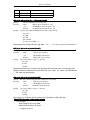
2.1.2 IEEE 1284 Bidirectional Parallel Interface
2.1.2.1 Specifications
Data Transmission: 8-bit parallel
Synchronization:
Externally supplied nStrobe signals
Handshaking:
nAck and busy signals
Signal Level:
TTL compatible
Connector :
ADS-B36BLFDR176 (Honda) or equivalent (IEEE 1284 Type B)
Switching between online and offline
The printer is not equipped with any online/offline switch. The printer is placed into offline
status in either of the followings:
1) When the power is turened on or until the printer becomes ready for data transmission
afterit is initialized by the reset signal (nlnit) from the interface.
2) During the self-test.
3) When the cover is open.
SP91 User Manual
4) During paper feeding using the paper fedd button.
5) When the printer stops printing due to a paper-end(in cases when empty paper supply is
detected by either the paper roll end detector or the paper roll near-end detector with a
printing halt due to paper shortage enabled by ESC c 4).
6) During macro executing standby status.
7) When an error has occurred.
Reverse data mode
The status data transmission from the printer to the host is processed in the nibble or byte mode.
At present, reverse data transmission by nibble.
NOTE
NOTE:At
·
Description
This mode allows data transmission from the asynchronous printer under the control
by the host.
Data transmissions in the Nibble mode are made via the existing control lines in units of
four bits. In the byte mode, data transmissions are processed by making the eight-bit data lines
bidirectional.
The both modes fall to process concurrently with the compatibility mode, thereby causing half
duplex transmission.
2.1.2.2 Interface Pin Signal Defination
Interface Pin Assignments for Each Mode
Compatibility
Pin
Source
1
Host
nStrobe
HostClk
2
Host/Ptr
Data0(LSB)
Data0(LSB)
3
Host/Ptr
Data1
Data1
4
Host/Ptr
Data2
Data2
5
Host/Ptr
Data3
Data3
6
Host/Ptr
Data4
Data4
7
Host/Ptr
Data5
Data5
8
Host/Ptr
Data6
Data6
9
Host/Ptr
Data7(MSB)
Data7(MSB)
10
Printer
nAck
PtrClk
11
Printer
Busy
PtrBusy/Data3, 7
12
Printer
Perror
AckDataReq/Data2, 6
13
Printer
Select
Xflag/Data1, 5
14
Host
nAutoFd
HostBusy
15
NC
ND
16
GND
GND
17
FG
FG
18
Printer
Mode
4-bits Mode
Logic-H
Logic-H
19
GND
GND
20
GND
GND
21
GND
GND
22
GND
GND
SP91 User Manual
23
GND
GND
24
GND
GND
25
GND
GND
26
GND
GND
27
GND
GND
28
GND
GND
29
GND
GND
30
GND
GND
31
Host
nInit
nInit
32
Printer
nFault
nDataAvail/Data0, 4
GND
ND
33
34
Printer
DK_STATUS
ND
35
Printer
+5V
ND
36
Host
nSelectIn
1284-Active
*NC: Not Connected
ND: Not Defined
NOTES: 1. A prefix “n” to signal names refer to low level active signals.
2. To the host provided with none of the signal lines listed above, both-way communication
fails.
3. For interfacing, signal lines shall use twisted pair cables with the return sides connected to
signal ground level.
4. Interfacing conditions shall be all based on the TTL level to meet the following characteristics
In addition, both rise and fall time of each signal shall be 0.5μs or less.
5. Data transmission shall not ignore the signal n Ack or Busy. An attempt to transmit data with
signal, nAck or Busy, ignored can cause data lose. (Data transmission for the printer shall be
made after verifying the nAck signal or while the Busy signal is at the low level.)
6. Interface cables shall be as min required short in length as possible.
Electrical Characteristics
DC Characteristics (Except Logic- H, + 5 V signals)
Characteristics
Symbol
Specifications
Min
Max
Conditions
Output High Voltage
VOH
*2.4 V
5.5 V
*IOH=0.32 mA
Output Low Voltage
VOL
-0.5 V
*0.4 V
*IOL=-12 mA
Output High Current
IOH
0.32 mA
-
VOH =2.4 V
Output Low Current
IOL
-12 mA
-
VOL=0.4 V
Input High Voltage
VIH
2.0 V
-
Input Low Voltage
VIL
-
0.8 V
Input High Current
IIH
-
-0.32 mA
VIH =2.0 V
Input Low Current
I IL
-
12 mA
VIL=0.8 V
Logic - H Signal Sender Characteristics
Characteristics
Output High Voltage
Symbol
VOH
Specifications
Min
Max
3.0 V
5.5 V
Conditions
While the
SP91 User Manual
Output Low Voltage
VOL
-
2.0 V
power is OFF
+5 V Signal Sender Characteristics
Characteristics
Symbol
Specifications
Min
Conditions
Max
Output High Voltage
*IOH=0.32 mA
Output Low Voltage
VOH
*2.4 V
5.5 V
While the power is
Output High Current
VOL
-
-**
OFF
Output Low Current
IOH
-
0.32 mA
VOH =2.4 V
IOL
-**
-
While the power is
OFF
** No guarantee is offered to VOL and I OL while the power is OFF.
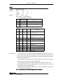
Parallel Data Receiving Timing
Parallel Interface Signal Timing Figure as follows(Compatibility Mode):
Reset printer by parallel
To enable the printer reset by nInit signal (PIN 31) in compatibility mode. Set nInit signal by
SWITCH DIP. To enable the printer reset, meet the following signal timing.
The signal is ignored when #36 nSelectIn /1284-Active is high in reverse mode.
·
DC characteristic
TTL Level
·
AC characteristic
Min reset pluse width:TRS 50μs (min)
NOTE:The prefix “n” named active-low
Reception of status from the printer through the bidirectional parallel interface
In the bidirectional parallel interface specifications, the printer status transmission is available by
SP91 User Manual
using the both-way communication facility in the Nibble/Byte Modes in accordance with the IEEE
1284.
In this case, different from in the RS-232 serial interface specifications, the real-time interruptions
from the printer to the host are disabled and thus precautions must be taken to the followings:
1) Allowable capacity of the printer internal buffer is 99 bytes (except ASB status), The status signals
exceeding this capacity will be discarded, To prevent possible loss of status, the host shall be ready
for data acception (Reverse Mode).
2) When ASB is used, the host is preferably in the wait state for data acception (ReverseIdle
Mode).When this state is not available, the host shall enter the Reverse Mode to always monitor the
presence of data.
3) When ASB is used, preference shall be given to the ASB status for transmission over the other
status signals. Once one ASB conditions changed, all ready to send ASB conditions from last time
that need to send together, then sending the latest ASB conditions.
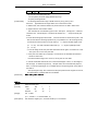
2.1.3 Ethernet Interface
2.1.3. 1Interface Specifications
Ethernet Type: Standard Ethernet (10M)
TCP/IP agreement: ETHERNET, ARP, IP, TCMP, IGMP, UDP, TCP, HTTP, DHCP;
Connector Type:
RJ45 (as table)
2.1.3.2 Interface connection
1.Default IP address “192.168.1.6”, IP port “9100”, checked by self-test list;
2.Link the printer to LAN, open IE and input the IP address of the printer, default “192.168.1.6”, Carriage
return to log in. After modifying the related information, then “Reset”;
3. If printing by Windows driver, install SP91 driver. After installing driver, find installed SP91 driver in
“printer and fax”. Choose attribute, then “Port”-“Add port”-choose “Standard TCP/IP Port”, operate
according its prompt.
4.Change driver to this port, test through printing test page.
Notes:
1.Default IP port 9100, normal condition that needn’t change;
2.Add “Standard TCP/IP Port”, when choosing “Device type”, to choose “Standard”.
2.1.3.3 Interface Pin Signal Definition
Pin NO.
Signal Name
Signal Source
1
TX+
Tranceive Data+ (Send signa+)
2
TX-
Tranceive Data+-(Send signa-)
3
RX+
Receive Data+ (Receive signal+)
4
N/C
Not connected(Blank)
5
N/C
Not connected(Blank)
6
RX-
Receive Data-(Receive signal-)
SP91 User Manual
7
N/C
Not connected(Blank)
8
N/C
Not connected(Blank)
2.1.4 USB Interface
2.1.4.1 Interface Specifications
Connector Type: Type B female interfaceB
Communication Agreement: USB2.0
Interface connection
2.1.4.1
2.1.4.1Interface
1. Connect printer to PC, and turn the power on;
2.Install Windows driver(SP91), At the page of ”Printer and fax”, find the installed driver ”SP91”, right click
and open the page of ”Attribute”, will have ”USB000n” at ”Port”(May be n is 1,2,3 or anothers, decided by
printer USB port), change the printer driver to this port and print test page;
Notes:
When use USB port,if turn the printer power off for a long time, printer driver (SP91) will be went off
automatically, this moment driver can not print normally,
right click to cancel offline print;
2.1.4.3 Interface Pin Signal Defination
Pin definition:
Pin NO.
1
Function
V Bus
Color
Red
Definition
Power +5V
2
3
4
DataData+
GND
White
Green
Black
DataData+
Ground
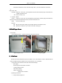
2.2 Printer Installation
2.2 Power Connector
NOTE : To guarantee the normal operation to the printer. Please use the standard power from our
company.
Pin Definition:
Pin NO.
Signal
1
2
+24
GND
3
SHELL
NC
F.G
SP91 User Manual
2.3 Drawer Connector
SP91 used RJ-11 6 connector,as follows:
Pin Definition as the following table:
Pin NO.
Signal Ground
1
Frame GND
2
Drawer kick-out drive signal 1
3
Drawer open/close signal
4
+24V
5
Drawer kick-out drive signal 1
6
Signal GND
Direction
--Output
Input
Output
-
SP91 User Manual
3
FUNCTIONS
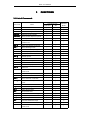
3.1 List of Commands
Command
Name
Command Type
Executive
Set
Standard
Mode
HT
Horizontal tab
¡
¡
LF
Print and line feed
¡
¡
CR
Print and carriage return
¡
¡
DLE EOT
Transmit real-time status
¡
¡
DLE ENQ
Send real-time request to printer
¡
¡
ESC !
Select print modes
ESC %
Select/cancel user-defined
character set
¡
¡
¡
¡
¡
¡
ESC &
Define user-defined characters
ESC *
Select bit-image mode
ESC 2
Select default line spacing
¡
¡
ESC 3
Set line spacing
¡
¡
ESC ?
Cancel user-defined characters
¡
¡
ESC @
Initialize printer
¡
¡
ESC a
Select justification
¡
¡
ESC D
Set horizontal tab positions
¡
¡
ESC i
Full cut
¡
¡
ESC J
Print and feed paper
¡
¡
ESC m
Partial cut
¡
¡
ESC V
Turn 90°
¡
¡
clockwise rotation
mode on/off
ESC c 5
Enable/disable panel butons
ESC d
Print and feed n lines
ESC t
Select character code table
ESC {
Turn upside-down print mode
¡
¡
¡
¡
¡
¡
¡
¡
¡
on/off
¡
(¡ )
ESC P
Cash draw command
¡
¡
FS p
Print NV bit image
¡
¡
FS q
Define NV bit image
¡
GS !
Set character size
¡
¡
GS *
Define downloaded bit image
¡
¡
GS ( A
Execute test print
GS ( B
Set printer parameter
GS /
Print downloaded bit image
¡
GS :
Start/end macro definition
¡
GS B
Turn white/black reverse print
mode on/off
¡
(¡ )
¡
¡
¡
●
¡
¡
¡
¡
SP91 User Manual
GS H
Select print position of HRI
¡
characters
GS I
Transmit printer ID
GS L
Set left margin
GS T
Set print position as printing origin
¡
GS V
Select cut mode and cut paper
¡
GS W
Set print area width
GS ^
Execute macro
GS a
Enable/disable automatic status
¡
¡
¡
(¡ )
¡
¡
(¡ )
(¡ )
¡
¡
back(ASB)
¡
¡
¡
¡
GS b
Turn smoothing mode on/off
¡
¡
GS f
Select font for HRI characters
¡
¡
GS h
Set bar code height
¡
¡
GS k
Print bar code
¡
●
GS r
Transmit status
¡
¡
GS v 0
Print grating bit image
¡
GS w
Set bar code width
GS ( K
Print QR code
●
¡
¡
¡
●
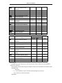
List of Chinese characters command
Command
FS !
Name
Set print modes for Chinese
character
FS &
Set Chinese characters mode
FS -
Turn underline mode on/off for
Chinese characters
FS .
Cancel Chinese mode
FS 2
Define user-defined Chinese
character
FS C
Select Chinese character code
system
FS S
Set Chinese character spacing
FS W
Turn quadruple-size mode on/off for
Chinese characters
Command Type
Executive
Set
Standard
Mode
¡
¡
¡
¡
¡
¡
¡
¡
¡
¡
¡
¡
¡
¡
¡
¡
Command Type
Executive command: The printer execute this command, it won’t influence the following data if
change this command.
Set command: Set the printer through the relative zone bit, the set will influence the following data.
Standard mode
¡ : Allowance.
(¡ ): To be valid when only the command locate the beginning of the line.
●: It is valid only no data in print buffer.
Page Mode
SP91 User Manual
¡ : Allowance.
▲: Set data only.
Forbid: Detail with parameter as print data.
Ignored: Ignore all command codes, include parameter, do not execute any operation.
3.2 Power Button and Buttons
3.2.1 Power Button
Power switch under the printer front side
Use ship type mode
NOTE:Connect the power correctly before turning the power on.
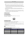
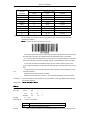
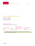
3.2.2 Panel Button
3.2.2.1 Paper Feed Button
blue
Alarm
Alarm(blue
blue)
Feed
red
Error
Error(red
red)
green
Power(green
green)
type
Ship
power switch
SP91 key panel picture
SP91 key panel picture
self-test:
NOTE:ESC c 5, enable/diable the button fuction. Push button to prohibit, it isn’t valid.
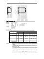
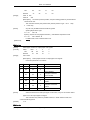
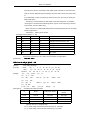
3.3 DIP Switch
SP91 has two DIP Switchs and printed agreed number, each function refer to the below sections;
SP91 User Manual
Can change from DIP setting utility
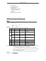
3.3.1 DIP Switch 1
DIP Switch 1
Switch
Fuction
ON
1
Chinese character mode
Character mode
2
Traditional/Simplified Chinese
BIG5
GB18030
OFF
3
Print speed
Low
High
OFF
4
---
---
---
OFF
5
---
---
---
OFF
6
---
---
---
OFF
NO.
7
8
Serial baud rate selection
OFF
Chinese character
mode
Refer to table:baud rate selection
Default
OFF
OFF
OFF
SP91 User Manual
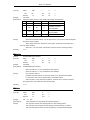
Baud Rate Selection
Transmission Speed(Baud rate
Switch NO.
BPS)
7
8
115200
OFF
ON
38400
OFF
OFF
19200
ON
OFF
9600
ON
ON
NOTE:BPS – bits per second bit/second
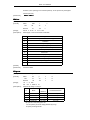
3.3.2 DIP Switch 2
DIP Switch 2
Switch
Function
NO.
ON
OFF
Line printing 48
Line printing 42
characters
characters
1
Select print valid width
2
Select print gray leve
Deepen
3
Select print paper width
Paper width 58mm
Lighten
Paper width 80mm
Buzzer doesn’t
4
Kitchen mode
Buzzer awake after
awake after paper
paper cut
cut
5
----
----
----
6
----
----
----
7
Alarm
Warn when closing
Warn when opening
the buzzer
the buzzer
8
----
----
---
Default
OFF
OFF
OFF
OFF
OFF
OFF
OFF
OFF
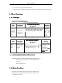
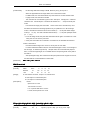
3.4 LED/Alarm
1)Power LED:Green
On:Power is stable.
Off: Power is not stable.
Standby State Indication:
State
Macro
state.
execution
Paper Out LED Flashing Pattern
ready
Recovery Conditions
Pressing the FEED button
executes the macro.
NOTE:A macro can be executed r times(r specifices the number of times to execute the macro) within
the specified definition range. The macro can be executed continuously or can be executed by
pressing the button. If the macro is executed by pressing the FEED button, the PAPER OUT
SP91 User Manual
LED bliks to indicate the macro execution ready state. ( see macro definition commands)
2)
Alarm LED:Blue
Flashing:Paper out, Cover open, The temperature of print head is extremely high, Autocutter error,
another mechanism error.
Off:Printer is ready to go.
3)ALARM:Buzzer
Sound
:Paper out, Cover open, The temperature of print head is extremely high, Autocuttererror,
Print the receipt under the back kitchen mode, another mechanism error.
:Printer is ready to go.
Quiet
NOTES:
�
Only two times when printing each receipt under the back kitchen mode;
�
Other fault conditions, only 15s with sound then closing by it.
3.5 Roll Paper Cover
Cover button
As the following picture,pointed out direction and push the button.
Open the paper cover
Install the paper
6 Self-test
3.6
Self-test that checks whether the printer is stable or not. If the self-test is correct, indicates that the
printer is stable except the interface what connect the host. Or it is unstable.
1) The printer has a self-test function that checks the followings:
·
Print quality
·
Interface type and its operate conditions
·
Control software version
·
DIP Switch settings
·
Built-in character set
Select printer character
2) Starting the self-test
1、Firstly install the paper roll
SP91 User Manual
2、Turn the power off, and press feed paper key
3、Turn the power on, about 1~3 seconds and release FEED paper key, will print self-test print.
9 Error Processing
3.9
9.1
1 Error Type
3.9
1) Error that automatically recover
Errors That Automatically Recover
Error LED Flashing Pattern
Error
Description
Recovery
Recovers
Print head
over-tem
perature
error
automatically
Print head
when
temperature is
the
print head is
over 57° C
below
45° C.
2) Errors that have the possibility of recovery
Errors That Can Possibly Recover
Error LED Flashing Pattern
Error
Description
Recovery
Auto
The auto cutter
If paper jams, after
cutter
does not work
solving this
error
correctly
problem, then
recovering by DLE
ENQ 1 or DLE
ENQ 2
9.2
2 Printer Operation When an Error Occurs
3.9
The printer executes the following operations when detecting an error.
·
Stops all printer operations for the selected paper section.
·
Goes BUSY.
·
Blinks the ERROR LED.
10 Status Conditions
3.10
The printer has the following two roll paper status condition sensor:
The printer has the following two roll paper status condition sensor:
1)Roll paper end sensor
SP91 User Manual
The sensor which detect whether paper is present or not. When the sensor detects a paper-end,
the printer stops printing.
2)Roll paper near-end sensor
The sensor which detect a near-end of a paper roll.
When the paper roll diameter becomes sufficiently small, the detects a near-end of the paper roll
and the PAPER OUT LED lights. If the sensor is enabled by ESC c 4, the printer stops printing.
NOTES:·Install the new roll paper and close the cover, the printer start to printer again.
·Paper near-end sensor ready by user.
3.11 Buffer-Full Printing
After the printer deal with one line dates in the buffer area, When the printer receive the continued date,
the printer will automatically print the processed date and feed paper one line (under the standard mode).
SP91 User Manual
4
CASE SPECIFICATIONS
4.1 External Dimensions and Mass
Height:144mm
Width:142mm
Depth:154mm
Mass:1300g(except for a roll paper)
4.2 Color
White、Black
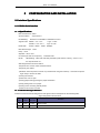
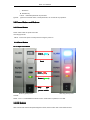
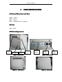
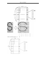
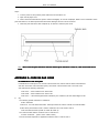
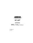
4.3 External Appearance
Paper
out
Key board
Power
Paper
Data line
Cash
Power
Cover
Interface
Interface
Interface
Figure 1:SP91 Plan
Figure 2:SP91 Back
SP91 Front
Figure 3:SP91
SP91 Side
Figure 4:SP91
SP91 User Manual
5
COMMANDS
5.1 Command Notation
[Name]
The name of the command
[Format]
The code sequence
[ ] k indicates the contents in brackets [ ] should be repeated k time.
[Range]
Gives the variable allowable ranges
[Description]
Describe the functions of the command.
[Particularize]
Go into particular use of commands.
[Notes]
Provide important information on setting and using the printer command, if
necessary.
[Default]
Gives the default values, if the commands with the parameters.
[Reference]
List the interrelated commands.
The data signed by < >H, is hexadecimal.
The data signed by < >B,is binary.
5.2 Explanation of Terms
(1) Receive buffer
The receive buffer is used to store data from the host computer. All received data is
stored in this buffer and processed in the order received.
(2) Print buffer
The print buffer is used to store image data for printing.
(3) Full printing buffer area
The printer buffer is full. When the printer buffer is full, if new printing data comings, the
data in the printing buffer area to be printed, and execute the operation of exchanging
the line. The operation the same as the LF commands.
(4) Initial position of line
Initial position of line conditions meets the falling points:
l
No printing data in the present printing buffer area (includes part empty data which
caused by blank and HT command)
l
Appoints the printing position that have not through ESC $ or ESC \ commands.
(5) Printable area
The maximum printable area of this printer is as follows:
①Standard mode, horizontal direction:
About 72.2mm
②Page mode,horizontal direction:
About 72.2mm
③Page mode, vertical direction:
About 117.3mm
(6) Print area
The print area set by commands, the print are £ printable area.
(7) Ignored
All commands in this condition, include the parameters which be read, then discarding,
but do not any operations.
(8) Inch
SP91 User Manual
Length unit. 1 inch=25.4mm.
(9) MSB
Most Significant Bit
(10) LSB
Least Significant Bit
(11)Baseline
The standard position of the character data what stocked in the print buffer area. The
following indicates the general characters position under the standard mode and page
mode:
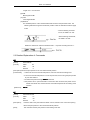
*1 When selecting character
font A, the width is 21 dots
When selecting character B,
the width is 16 dots.
Rotate the characters under the standard mode:(only when selecting the font A)
5.3 Detailed Explanation of Commands
HT
[Name]
Horizontal tab
[Format]
ASCII
HT
HEX
09
Decimal
9
[Description] Moves the print position to the next horizontal tab position.
[Particularize]
• If didn’t set the next horizontal tab position, then this command will be ignored.
• If the next horizontal tab position is out of the print area, then moving the print position
to “print area width+1.
• Set horizontal position through ESC D command.
• Print position set on “print area width+1”and receive this command, the printer moves
ahead when buffer full, and execute the horizontal tab position at the starting of the
next line.
[Reference]
ESC D
LF
[Name]
Print and line feed
[Format]
ASCII
LF
HEX
0A
Decimal
10
[Description]
Prints the data in the print buffer and feeds one line, based on the current line spacing.
Moves the print position to the next horizontal tab position.
[Note]
This command set the print position to the starting of the line.
SP91 User Manual
[Reference]
ESC 2, ESC 3
CR
[Name]
Print and carriage return
[Format]
[Description]
ASCII
CR
HEX
0D
Decimal
13
Allow feed paper automatically, the function of this command is the same as LF
command.
This command will be ignored when do not allow to feed paper automatically.
[Particularize]
·
For serial interface mode, the feed paper function of this command could be ignored.
· ·
This command set the print position to the starting of the line.
LF
[Reference]
DLE EOT n
[Name]
Transmit real-time status
[Format]
ASCII
DLE
EOT
n
HEX
10
04
n
16
4
n
Decimal
[Range]
[Description]
1≤
n≤ 4
Transmit the real-time status. Parameter n used to be appointed the printer transmitting
status. The definition as follows:
n = 1: Transmit printer status.
n = 2: Transmit offline cause status.
n = 3: Transmit error cause status.
n = 4: Transmits roll paper sensor status.
[Particularize]
• The printer transmits the current status, each status is one byte data.
• When transmitting the status, the printer can not confirm whether the host can
receive the data or not.
• Starts to execute when the printer received this command.
• In serial interface mode, even if the printer lacated on offline status, full receiving
buffer, or executed this command when error occurred.
• In parallel interface mode, can not execute this command when the printer is busy.
When the printer located in offline status, Memory Switch 1-3 lacated on ON, the
printer can not go to BUSY status.
• Reply (ASB) automatically through GS a command, need to make a distinction the
sending status of DLE EOT command and ASB status. (Refer to appendix C,
transmitting status identification )
• If the printer don’t be selected peripheral device command ESC = , the selected
command remain in effect.
[Notes]
·
Whenever get <10>H<04>H<n>(1 £
n£
4) data sequence, will transmit the
status.
For example in the following commands:
ESC *
·
m nL nH d1 ... dk , d1=<10>H, d2=<04>H, d3=<01>H
Can not use this command when there are 2 or more bytes in the command.
For example:
SP91 User Manual
If want to send ESC 3 n to the printer, before sending the n, DTR (for host is
DSR)will be changed to MARK,so before receiving the n, interrupt DLE EOT 3. The
code of DLE EOT 3 <10>H will deal with as the code of ESC 3 <10>H.
n = 1 Printer status
Bit
Off/On
Hex
Decimal
0
Off
00
0
Not used. Select off.
1
On
02
2
Not used. Select on.
2
On
04
4
Not used. Select on.
Off
00
0
Online.
On
08
8
Offline.
On
10
16
Off
00
0
On
20
32
Off
00
0
Feed paper button switch off.
On
40
64
Feed paper button switch on.
Off
00
0
3
4
5
6
7
Function
Not used. Select on.
Do not wait online error recovery.
Wait online error recovery.
Not used, Select off.
NOTE:bit 5:Online error is the process that the printer will execute waiting switch on/off during the
macro command and self-test.
n = 2 :Offline status
Bit
Off/On
Hex
Decimal
0
Off
00
0
Not used. Select off.
1
On
02
2
Not used. Select on.
Off
00
0
Cover is closed.
On
04
4
Cover is open.
Off
00
0
On
08
8
On
10
16
Not used. Select on.
Off
00
0
No paper end stop.
On
20
32
Printing stopped by paper end.
Off
00
0
No error.
On
40
64
Error occurred.
Off
00
0
Not used. Select off.
2
3
4
5
6
7
Function
Paper is not being fed by the paper
FEED button.
Paper is being fed by the paper
FEED button.
Bit 5:Turn on when stopping print when the no paper sensor detected paper end.
n = 3: Error status
Bit
Off/On
Hex
Decimal
0
Off
00
0
Not used. Select off.
1
On
02
2
Not used. Select on.
Off
00
0
No mechanical error.
On
04
4
Mechanical error occurred.
Off
00
0
No auto cut error.
On
08
8
Auto cut error occurred.
4
On
10
16
Not used. Select on.
5
Off
00
0
No unrecoverable error.
2
3
Function
SP91 User Manual
6
7
On
20
32
Unrecoverable error occurred.
Off
00
0
No automatically recoverable error.
Off
40
64
On
00
0
Automatically recoverable error
occurred.
Not used. Select off.
Bit 2:While the cover is opening, the printer showed it as the mechanical error.
Bit 6:If the temperature of print head is extremely high, bit 6 will be turn on, until temperature of the
print head effectively comes down or open the cover during printing.
n = 4: Roll paper sensor status
Bit
Off/On
Hex
Decimal
0
Off
00
0
Not used. Select off.
1
On
02
2
Not used. Select on.。
Off
00
0
On
0C
12
On
10
16
Not used. Select on.
Off
00
0
Paper near-end sensor:with paper.
On
60
96
Off
00
0
No paper end detected by paper
near-end sensor.
2,3
4
5,6
7
Function
Paper near-end detected by paper
near-end sensor.
Paper near-end detect printing to the
paper end.
Not used. Select off.
DLE ENQ
ENQ, GS a, GS r
[Reference]
DLE ENQ n
[Name]
Real-time request to printer
[Format]
ASCII
Hex
Decimal
n≤
DLE
ENQ
n
10
05
n
16
5
n
[Range]
1≤
[Description]
Responds to a request in real-time from the host computer. N appoint the following
2
functions
n
1
2
[Particularize]
·
Function
Recovers from a recoverable error and restarts printing from the
line where the error occurred.
Recovers from a recoverable error after clearing the receive and
print buffers.
This command only effected when the auto cutter error, cover open.
• Deal with the data once the printer receive this command.
· Though the printer is offline, full printing buffer or serial interface mode error, always
execute this command.
·
In parallel interface mode, this command can not be executed when the printer is
busy. When Memory Switch 1-3 is ON,even the printer is offline, the printer do not set
BUSY.
·
DLE ENQ 2 allow that the printer recovers after clearing receiving buffer area and
printing area. When the printer keep the error occurred, it located in effective set ( as
SP91 User Manual
ESC !, ESC 3 etc). Completely initialize the printer by this command and ESC @. This
command only effects for the error which can be recovered, except for print head
temperature error.
[Notes]
Whenever receive <10>H<05>H<n> (1 ≤
·
n≤
2) data sequence,will send status.
For example:
ESC * m nL nH dk, d1 = <10>H, d2 = <05>H, d3 = <01>H
·
In the command data includes 2 or more bytes, can not use this command.
For example:
If want to send ESC 3 n to the printer, but before sending the n, DTR ( For the host is
DSR)will change to MARK, hence before receiving n, DLE ENQ 2 to discontinue. The
code of DLE ENQ 2 <10>H will be processed by the code <10>H of ESC 3 .
LE EOT
[Reference]
ESC S0
[Name]
Set character double print
[Format]
ASCII
ESC
S0
Hex
1B
0E
27
14
Decimal
[Range]
-
[Description]
After setting, all characters will be printed double width(Chinese character invalid)
[Particularize]
[Default]
Cancel by carriage return or ESC DC4
-
ESC DC4
[Name]
Cancel character double width print
[Format]
ASCII
ESC
DC4
Hex
1B
14
27
20
Decimal
[Range]
-
[Description]
Cancel double width by ESC SO
[Particularize]
[Default]
Refer to ESC
S0
-
ESC ! n
[Name]
Select print modes
[Format]
[Range]
ASCII
ESC
Hex
Decimal
0≤
n
!
n
1B
21
n
27
33
n
≤ 255
[Description] Select print modes by the data of appointing parameter n.The definition of n as follows:
Bi
t
0
Off/On
Hex
Decimal
Off
00
0
Function
Character type A (12 ×
24)。
SP91 User Manual
On
01
1
Character type B (9 ×
1
On
D4
212
Set double width print
2
On
D5
213
Cancel double width print
-
-
--
Undefined
-
-
--
Undefined
Off
0
0
Cancel double height mode
On
10
16
Set double height mode
Off
00
0
Cancel double width mode
On
20
32
Set double width mode
-
-
--
Undefined
-
-
--
Undefined
-
-
--
Undefined
3
4
5
6
7
[Particularize]
·
17)。
When selecting the double height and width mode at the same time, print 4 times
characters.
·
The printer can add the underline to all characters, but can not add the
underline to blank and clockwise switching 90 which set by HT command.
·
When the double or more height characters in one line, all characters will be
justified
along basis line.
·
[Default]
This command only effect for characters, Chinese invalid
n=0
ESC $ nL nH
[Name]
[Format]
Set absolute print position
ASCII
ESC
$
nL
nH
1B
24
nL
nH
27
36
nL
nH
Hex
Decimal
[Range]
0≤
nL ≤
0 ≤nH
[Description]
255
≤ 255
Set the distance from the beginning of one line to the position which will be printed the
characters.
The distance from the beginning of one line to the position which will be printed is:
[(nL + nH×
256)
×0.125 mm ].
Particularize] · The set which be appointed as the print area will be ignored.
In stable mode, use the horizontal motor unit (x).
ESC \, GS $, GS \
[Reference]
ESC % n
Name]
Select/cancel user-defined character set
[Format]
ASCII
ESC
Hex
1B
25
n
27
37
n
Decimal
[Range]
0≤
%
n
n ≤ 255
[Description] Select/cancel user-defined character set.
·
When the LSB of n is 0, the user-defined character set is canceled.
·
When the LSB of n is 1, the user-defined character set is selected.
SP91 User Manual
[Particularize] ·
When select cancel user-defined character set, automatically select inner character
set.
·
n only valid at least significant bit.
[Default]
n=0
ESC &, ESC ?
[Reference]
ESC & y c1 c2 [x1 d1...d(y × x1)]...[xk d1...d(y ×xk)]
[Name]
Define user-defined characters
[Format]
ASCII
ESC
Hex
Decimal
[Range]
&
y c1 c2 [x1 d1...d(y×x1)]...[xk d1...d(y×xk)]
1B
26
y c1 c2 [x1 d1...d(y×x1)]...[xk d1...d(y×xk)]
27
38
y c1 c2 [x1 d1...d(y×x1)]...[xk d1...d(y×xk)]
y=3
32 ≤ c1 ≤c2 ≤126
0≤
x≤
12
(when font A (12 ×
0≤
x≤
9
(when font B (9
0≤
d1...d(y×xk) ≤255
24) is selected)
× 17) is selected)
[Description] Define user-defined characters.
·
y specifies the number of bytes in the vertical direction.
·
c1 specifies the beginning character code for the definition, and c2 specifiesthefinal
code.
·
x specifies the number of dots in the horizontal direction.
[Particularize]·
Characters code can be defined: ASCII from <20>H to <7E>H (95 characters).
·
The continued characters code of several characters can be undefined. When only
need one character, so c1 = c2。
·
d is the dot data of characters. Dot mode is from the left in horizontal direction. The
right left dots are blank.
·
Define the data of user-defined character is (y×x) bytes.
·
Set the relevant of printing dot is 1 or 0 which is the relevant of do not printing the
dots.
·
Define the different user-defined character mode for each character type by this
command. Set the character type by ESC ! or ESC M .
·
User-defined character and download bit image can not define at the same time.
When executing this command, download bit image will be cleared.
· Under the following situations,
user-defined characters will be cleared:
① Execute ESC @.
② Execute GS *.
③ Execute ESC ?.
④ The printer reset or turn the power off.
·
When the user-defined characters defines in character typeB (9 ´
to the highest valuable bit of the third byte in the vertical direction data.
[Default]
[Reference]
Inner character font
ESC % , ESC ?
[For example]
·
When setting the character type A (12
× 24).
17), only effect
SP91 User Manual
· When set character type B
(9 ´
17).
SP91 User Manual
ESC * m nL nH d1... dk
[Name]
Select bit-image mode
[Format]
ASCII
[Range]
ESC
*
m nL nH d1...dk
Hex
1B
2A
m nL nH d1...dk
Decimal
27
42
m nL nH d1...dk
m = 0, 1, 32, 33
0 ≤nL ≤255
0 ≤nH
0≤
d≤
≤3
255
[Description] Selects bit-image mode by m, the bit image dot set by nL and nH, as above table:
m
Vertical direction
Mode
8-dot
0
single-density
8-dot
1
double-density
3
24-dot
2
single-density
3
24-dot
3
double-density
Horizontal direction
Dot
Dot density
Dot density
Data number (K)
8
67.7 dpi
101.6 dpi
8
67.7 dpi
203.2 dpi
24
203.2 dpi
101.6 dpi
(nL + nH ×
256)
×3
24
203.2 dpi
203.2 dpi
(nL + nH ×
256)
×3
nL + nH×
256
nL + nH ×256
Dpi: {1 inch}/25.4mm print dot
[Notes]
If the data of m over the defined range, then the data of n and after n will be dealt as the
rule data.
·
nL and nH indicates the bit-image data in the horizontal direction. Calculate the dot
through nL + nH
·
× 256.
If input the bit-image data that overs the printable dots in one line, then the over data
will be ignored.
·
d indicates bit-image data. Set the relative bit to 1 and print one point, or set to 0 and
do not print one point.
·
If the printable width which set by GS L and GS W is smaller than the data which
sent by ESC *, Then executing the following operation to the line which have problems
SP91 User Manual
(but the printing can not over the max printable area):
① The printable width extend to the right and meet the data content.
② If the step ① can not apply the enough width to the data, so the left will be
decreased to apply the relative data. For the bit data in the single density mode (m
= 0, 32), The printer has two points: for the bit dat in the double density mode (m =
1, 33), the printer prints one point. When calculating the data content in one line,
these have to consider.
· After printing one bit-image, the printer return to the common data dealing mode.
·
This command won’t be affected by printing mode( bold、overlapping、underline、
character size、or inverse printing), except for upside down print mode.
·
·
The following figures describes the the relationship of image data and printing dot.
·
8-dot bit-image is selected::
24-dot bit-image is selected:
SP91 User Manual
ESC 2
[Name]
Select default line spacing
[Format]
ASCII
ESC
2
Hex
1B
32
27
50
Decimal
[Description]
Set the line spacing to 3.75mm (30 ´
0.125mm).
[Note]
Line spacing set independently in stable mode and page mode.
[Reference]
ESC 3
ESC 3 n
[Name]
Set line spacing
[Format]
ASCII
ESC
3
n
Hex
1B
33
n
Decimal
27
51
n
[Range]
0≤
n ≤ 255
[Description]
Set line spacing [n ×
[Notes]
·
Sets line spacing independently in stable mode
·
In stable mode, uses vertical unit (y).
[Default]
n = 30
[Reference]
ESC 2
0.125mm].
ESC ? n
[Name]
Cancel user-defined characters
[Format]
ASCII
ESC
?
n
1B
3F
n
63
n
Hex
Decimal
27
[Range]
32 ≤
[Description]
Cancel user-defined characters.
[Notes]
·
n≤
126
This command stops the type which defined for character code, character code set
by n
. After canceling the user-defined character, prints with inner character relative mode.
·
Select character type by ESC !, this command defect the type which defined the
pointed code.
·
If one of the user-defined characters do not define, then the printer ignore this
command.
ESC & , ESC %
[Reference]
ESC @
[Name]
Initialize printer
[Format]
ASCII
Hex
Decimal
[Description]
ESC
@
1B
40
27
64
Clears the data in the print buffer and resets the printer modes to the modes that were in
effect when the power was turned on.
[Notes]
·
The set of DIP swith and Memory Switch won’t check.
·
The data in receiving buffer area won’t be cleared.
SP91 User Manual
·
Macro definition won’t be cleared.
ESC a n
[Name]
Select alignment mode
[Format]
ASCII
ESC
Hex
1B
61
n
Decimal
27
97
n
n£
a
2, 48 £
n£
n
[Range]
0£
[Description]
Put one line date alignment as the point position
50
Select alignment type by n
n
Alignment
0, 48
Left alignment
1, 49
Middle
2, 50
[Notes]
Right alignment
· At the standard mode, only at the beginning of the line deal with, this command will effect.
Input this command in page mode, the printer only execute interior sign operation.
This command is not effect for page mode.
This command executed alignment in print area.
This command align blanket area by HT , ESC $ or ESC \.
[Default]
n=0
[For example]
Left alignment
Middle
Right alignment
ESC D n1 . . . nk NUL
[Name]
Set horizontal tab positions
[Format]
ASCII
Hex
Decimal
1≤
[Range]
0≤
[Description]
ESC
D
n1 . . . nk NUL
1B
44
n1 . . . nk 00
68
n1 . . . nk 0
27
n ≤ 255
k
≤ 32
Set horizontal tab positions.
·
n specifies the number from the beginning of one line, uses to set horizontal
position.
[Notes]
·
k indicates the total data which set by horizontal position.
·
Horizontal position as a data to store, this data is [character width ´
n], is
measuring from the beginning of the line. The character width includes the right spacing
of the character, and double width character set by double width of stable character.
·
This command delects the horizontal position which set before.
·
When set n = 8, the print position moved to the ninth row by sending HT.
·
Could be set position to 32 (k = 32). The data overs 32 will be dealt as normal data.
SP91 User Manual
As sort ascending to transmit [n] k and put one NUL 0 at last.
·
When [n] k is less than or equal to the fore data, sets position which be finished, and the
continued data dealt as normal data.
·
ESC D NUL cancel all horizontal position.
·
Even if changes the character width, the fore specified horizontal position also do not
change.
·
For stable and page mode, character width will be memoried.
[Default]
Default position is 8 character spacing (raw 9,17,25 ...) of type A (12 ´
[Reference]
HT
24).
ESC i
[Name]
Full cut
[Format]
ASCII
ESC
Hex
Decimal
i
1B
69
27
105
[Description]
After receiving this command, the printer executes full cut.
[Note]
As it won’t feed paper when executing this command, please assures that feed
paper5mm or more before executing this command next time, to avoid that the cutter be
damaged.
[Default]
The default is partial cut mode.
ESC J n
[Name]
Print and feed paper
[Format]
ASCII
ESC
J
n
Hex
1B
4A
n
Decimal
27
74
n
[Range]
0≤
n ≤ 255
[Description]
Prints and outputs the data in print buffer area, and feed paper [n ×
[Notes]
·
After printing, this command set the original position to the beginning of one line.
·
The feed paper quantity do not affect the data which set by ESC 2 or ESC 3.
·
In stable mode, the printer uses vertical unit(y).
0.125 mm ].
ESC m
[Name]
Partial cut
[Format]
ASCII
[Description]
[Note]
ESC
m
Hex
1B
6d
Decimal
27
109
The printer received this command, then executing partial cut at present position.
As the printer do not feed paper when executing this command, so before executing
this command in the next time, assure that feed paper at least 5mm or more, prevent cutter
broken.
[Default]
Partial cut mode is default.
ESC \ nL nH
[Name]
Set relative print position
[Format]
ASCII
ESC
\
nL
nH
SP91 User Manual
Hex
Decimal
1B
27
5C
nL
nH
92
nL
nH
0 ≤nL
≤ 255
0 ≤nH ≤
255
[Range]
[Description]
On basis of present position, set print starting position by horizontal and
vertical motor unit.
·
This command set the print position from present position to [(nL + nH
× 256)
× 0.125 mm]。
[Notes]
·
Any set over printable area which will be ignored.
·
Spacing N points the right:
nL + nH ´
256 = N
Spacing N point the left: (negative direction ), uses 65536 complement code.
nL + nH ´
·
256 = 65536 - N
In stable mode, uses horizontal motor unit.
ESC $
[Reference]
ESC c 3 n
[Name]
Select paper sensors to output paper-end signals
[Format]
ASCII
Hex
Decimal
ESC
1B
27
c
3
n
63
33
n
99
51
n
0 ≤ n ≤255
[Range]
[Description]
·
Select paper sensors to output paper-end signals.
Uses each parameter n as follows:
Bit
Off/On
Hex
Decimal
0
Off
-
-
1
Off
00
0
On
02
2
2
Off
-
-
3
Off
00
0
On
08
8
-
-
-
4-7
[Notes]
·
Function
Undefined.
Roll paper near-end
sensor disable.
Roll paper near-end
sensor enable.
Undefined.
Roll paper end sensor
disable.
Roll paer end sensor
enable.
Undefind.
Select several sensors and input signal. In this case, if any one of sensors detect
paper out, it will output paper out signal.
·
This command only effects to parallel interface, in serial interface mode, this
command will be ignored.
[Default]
n=0
ESC c 4 n
[Name]
Select paper sensors to stop printing
SP91 User Manual
[Format]
ASCII
ESC
Hex
c
1B
Decimal
27
4
n
63
34
n
99
52
n
[Range]
0 ≤n ≤255
[Description]
Selects the paper sensor to stop printing when paper end detected:
Bit
Off/On
Hex
Decimal
0
Off
-
-
1
On
00
0
Off
02
2
-
-
-
2-7
[Notes]
·
Fuction
Undefinded.
Roll paper near end
sensor disabled.
Roll paper near end
sensor enabled.
Undefined.
When this command enables one roll paper sensor, only uses the related roll paper,
the printer will be stopped.
·
When paper end sensor detects the end of paper, the printer stops printing and
enters to offline condition.
·
[Default]
When bit 1 is on, the printer selects paper near end sensor and stops printing.
n=0
ESC c 5 n
[Name]
Enable/disable panel buttons
[Format]
ASCII
Hex
ESC
c
5
n
1B
63
35
n
27
99
53
n
Decimal
[Range]
0 ≤n ≤255
[Description]
Enable/disable panel buttons.
[Notes]
·
When the LSB of n is 0, the panel buttons are enabled.
·
When the LSB of n is 1, the panel buttons are disabled.
·
Only uses the LSB of n.
·
If disable the panel buttons, so close the printer cover, all buttons are disable.
·
For this printer, the only one panel button is feed paper button.
·
When locates in macro executing conditions, however how to set this command,
feed paper button are enable. But can not feed paper.
[Default]
n=0
ESC d n
[Name]
Print and feed n lines
[Format]
ASCII
Hex
ESC
d
n
1B
64
n
100
n
Decimal
[Range]
0≤
[Description]
[Notes]
27
n ≤ 255
Prints the data in the right buffer and feeds the paper n.
·
This command set the print starting position to line starting position.
·
This command can not effect the line spacing which set by ESC 2 or ESC 3.
·
The max feed paper measure is 1016 mm{40inch}. If the specified feed paper
SP91 User Manual
measure (n line spacing) overs 1016mm{40inch}, so the printer only feed paper
1016mm{40 inch}.
ESC 2 , ESC 3
[Reference]
ESC t n
[Name]
Select character code table
[Format]
ASCII
ESC
Hex
t
1B
Decimal
74
27
5, 16 ≤n
n
n
116
n
[Range]
0 ≤n ≤
≤ 19, n = 255
[Description]
Select page n from the character code table.
n
Page
0
PC437 [USA Standard Europe]
1
Katakana
2
PC850 [Multilingual]
3
PC860 [Portuguese]
4
PC863 [Canadian-French]
5
PC865 [Nordic]
16
WPC1252
17
PC866 [Cyrillic 2]
18
PC852 [Latin 2]
19
PC858 [Euro]
255
Space page
[Default]
n=0
[Reference]
Character tables
FS p n m
[Name]
[Format]
[Range]
[Description]
Print NV bit image
ASCII
FS
p
n
m
Hex
1C
70
n
m
Decimal
28
112
n
m
1≤
n
≤ 255
0≤
m≤ 3 , 48≤m ≤
51
Prints NV bit image n using m.
Vertical
m
Mode
0, 48
Normal
203.2 dpi
203.2 dpi
1, 49
Double-width
203.2 dpi
101.6 dpi
2, 50
Double-height
101.6 dpi
203.2 dpi
3, 51
Quadruple
101.6 dpi
101.6 dpi
direction
Horizontal direction
dpi: per 25.4 mm{1inch} print dot
·
n is the quantity of NV bit image( defined by ES q).
·
m specify bit image mode
SP91 User Manual
[Particularize]
·
NV bit image defined bit image in NVM. Define by FS q, print by FS P.
·
When the appointed NV bit image absent, this command is invalid.
·
In stable mode, this command effects only when there are no data in buffer area.
·
In page mode, this command is invalid.
·
This command do not effected by print mode(bold print,overlap print,underline,
character size,anti-white print or character 90 rotation etc.),except reversal print
mode.
·
If set the NV bit image print area width
which is less than a vertical line by GS L
and GS W, Executes the following operation only for problem line. In NV bit image
mode, a vertical line means the dot of normal mode (m
= 0, 48) and double height
mode (m
= 1, 49) and quadruple mode
(m
= 2, 50),two dots of double width mode (m
= 3, 51).
① In NV bit image mode, the print area width extendes to right to a vertical line. In this
case, print can not over the print area.
② If the print area width can not extend to a vertical line, the left blank decreases to
contain a vertical line.
·
If the download bit image overs one line, do not print the over data.
·
In normal and double width mode, this command feed paper n dots, n is the height of
NV bit image, In double height and qu
adruple mode, this command feed paper 2n
dots, n is NV bit image height, do not related with the line spacing which set by ESC 2
and ESC 3.
·
After printing bit image, this command set the print position at the original of one line,
and deal with the continued data as normal data.
[Reference]
ESC *, FS q , GS / , GS v 0
ESC P m n1 n2
[Name]
Set cash drawer command
[Format]
ASCII
ESC
Decimal
Hex
[Range]
27
P
m
n1
112
m
n1
70
m
n1
1b
n2
n2
n2
In cash drawer connector, output n1 n2, asked n2≥n1
m=0,48 output on cash drawer pin2.
m=1,49 output on cash drawer pin5.
[Description]
Notes:
Open time is t1×2ms
Turn-off time is t2×2ms
If t2< t1, printer deal with t2=t1×2ms
If t2<50, interior printer set t2 to 50
FS q n [xL xH yL yH d1...dk]1...[xL xH yL yH d1...dk]n
[Name]
Define NV bit image
[Format]
ASCII
FS
q
n [xL xH yL yH d1...dk]1...[xL xH yL yH d1...dk]n
SP91 User Manual
[Range]
Hex
1C
71
n [xL xH yL yH d1...dk]1...[xL xH yL yH d1...dk]n
Decimal
28
113
n [xL xH yL yH d1...dk]1...[xL xH yL yH d1...dk]n
1 ≤n ≤
0≤
255
xL ≤255
0 ≤xH
≤ 3 (when 1 ≤ (xL+ + xH × 256) ≤ 1023
≤ 255
0 ≤ yH ≤ 1 (when 1 ≤ (yL+yH × 256) ≤ 288
0 ≤ d ≤ 255
k = (xL+xH × 256) × (yL+ + yH ×256) × 8
0≤
yL
Total defined data area = 192K byte
[Description]
Set NV bit image by specified n.
·
n specify the quantity of NV bit image.
·
xL, xH for defined NV bit image points the dot of horizontal direction (xL+
xH ×
+
256)
×8.
yL, yH for defined NV bit image points the dot of vertica direction (yL+yH ×
·
256)
× 8.
[Particularize]
·
data,
This command cancels all defined NV bit image by this command..The definded
the printer can not defind anyone of data repeatly. If repeat certain data, so all data
should be sent once again.
·
During deal with this command to finish reseting hardware, can not execute
operation (contains when the cover is open to initialize the print head position,
mechanism
feed
paper by feed paper button etc.)
·
During deals with this command, when writing data to user NV memory, the printer is
busy and stop receiving data. So forbid to transmit data during execute this command,
contain real-time command.
·
NV bit image is one bit image which definds in NVM. Prints by FS p which defined by
FS q.
·
In stable mode, This command only effecs on the original line.
·
In page mode, this command is invalid.
·
The 7 bytes <FS~ yH> of this command, after normal dealing with, this command
effecs.
·
When the data quantity overs the left capacity range, the printer processes the range
which defined by xL, xH, yL, yH.
·
At the first group bit image, when any parameters in xL, xH, yL, yH overs the defined
range, this command is disabled.
·
At any one of group bit image except for the first group, when the printer meets that
xL,xH, yL, yH overs the defined scale, stops processing this command, and begins to
write NV image. At this moment, the undefined NV bit image (undefined)is disabled,
but any NV bit image defined before always affects.
·
d indicates defined data. At the data (d), one bit specifies one dot which need to
print and one 0 bit specifies one dot which do not need to print.
·
This command put n to define as the quantity o NV bit image. The quantity goes up
from bit image 01H. So the first data group [xL xH yL yH dl...dK] is the NV bit image
01H. The last data group [xL xH yL yH dl...dK] is the NV bit image n. The total the same
as the NV bit image quantity which be set by FS p.
·
One NV bit image defined data consists of [xL xH yLl xH dl...dK]. So, when only has
SP91 User Manual
one NV bit image n=1, the printer only processes the data group [xl xH yL yH dl...dK]
once. The printer uses ([data:(xL+xH×256) × (yL+yH×256) × 8]+[header:4]) bytes of
the NV memory.
·
The definded area of this printer is 192K bytes (max). This command can define
several bit images, but can’t define the bit image which the total capacity [bit image
data+head] overs 192K bytes.
·
Whatever how to set DIP switch 2-1, the printer enters “busy” before writing NV
memory.
·
Even set ASB, the printer do not send the ASB status or execute status test during
process this command.
·
When receive this command during macro definition, the printer stops macro
definition and executes this command.
· Once defines one NV bit image, it can’t be executed ESC @, and deleted when reset
and power off.
·
This command only executes the definition of NV bit image, do not execute print. NV
bit image print executed by FS p.
[Notes]
·
Writes command frequently which could be broken the NV memory.
So, suggests that executes the written operation less than ten times.
After the process of putting one bit image into NV memory, the printer executes one
hardware reset operation. So, defines the user-defined character, download bit image
and macro after finishing this command. The printer clears receive and print buffer area,
and reset to the effective mode when turing the power on. At this moment, the switch
DIP set will be checked once again.
[Reference]
FS p
[Examples]
When xL = 64, xH = 0, yL = 96, yH = 0.
SP91 User Manual
FS p n m
[Name]
[Format]
[Range]
Print NV bit image
ASCII
FS
p
n
m
Hex
1C
70
n
m
Decimal
28
112
n
m
1
0
[Description]
≤
≤
n
≤ 255
m≤
3 , 48≤m
≤ 51
Prints NV bit image n using m.
m
Mode
Vertical direction
Horizontal direction
0, 48
Normal
203.2 dpi
203.2 dpi
203.2 dpi
101.6 dpi
101.6 dpi
203.2 dpi
101.6 dpi
101.6 dpi
1, 49
2, 50
3, 51
Double
-width
Double
-height
Quadru
SP91 User Manual
ple
dpi: per 25.4 mm{1inch} print dot
[Particularize]
·
n is the quantity of NV bit image( defined by ES q).
·
m specify bit image mode
·
NV bit image defined bit image in NVM. Define by FS q, print by FS P.
· When the
appointed NV bit image absent, this command is invalid.
· In stable mode, this command effects only when there are no data in buffer area.
· In page mode, this command is invalid.
·
This command do not effected by print mode(bold print,overlap print,underline,
character size,anti-white print or character 90 rotation etc.),except reversal print
mode.
· If set the NV bit image print area width
which is less than a vertical line by GS L and
GS W, Executes the following operation only for problem line. In NV bit image mode,
a vertical line means the dot of normal mode (m
(m
= 2, 50),two dots of double width mode (m
(m
= 3, 51).
= 0, 48) and double height mode
= 1, 49) and quadruple mode
① In NV bit image mode, the print area width extendes to right to a vertical line. In this
case, print can not over the print area.
② If the print area width can not extend to a vertical line, the left blank decreases to
contain a vertical line.
·
If the download bit image overs one line, do not print the over data.
· In normal and double width mode, this command feed paper n dots, n is the height of
NV bit image, In double height and qu
adruple mode, this command feed paper 2n
dots, n is NV bit image height, do not related with the line spacing which set by ESC 2
and ESC 3.
·
After printing bit image, this command set the print position at the original of one line,
and deal with the continued data as normal data.
[Reference]
ESC *, FS q , GS / , GS v 0
GS ! n
[Name]
Select character size
[Format]
ASCII
Hex
Decimal
[Range]
0≤
(1
[Description]
GS
1D
29
!
n
21
n
33
n
n ≤255
≤ vertical ≤ 8, 1 ≤horizontal≤ 8)
Set character height by 0-2, character width by 4-6. As follows:
SP91 User Manual
Hex
Decimal
Width
00
0
1(Standard)
10
16
2(Double width)
20
32
3
30
48
4
40
64
5
50
80
6
60
96
7
70
112
8
Set character width
[Notes]
·
This command affects to all characters (English characters and Chinese) except for
HRI character.
· If n is out of the definition scale, this command will be ignored.
·
In stable mode, the vertical direction is the feed paper direction.
[Default]
n=0
[Reference]
ESC !
GS * x y d1..d( x y 8 )
[Name]
Defines down-load bit image
[Format]
ASCII
GS
*
x
y
d1...d( x ´ y ´ 8 )
Hex
1D
2A
x
y
d1...d( x ´ y ´ 8 )
Decimal
29
42
x
y
d1...d( x ´ y ´ 8 )
[Range]
[Description]
1 ≤x
≤ 255
1 ≤ y ≤ 48 (x × y × 1536)
0 ≤ d ≤255
Specifies dot by x and y, and defines the down-load bit image.
· x specify horizontal dot.
· y specify vertical dot.
[Notes]
·
Horizontal direction dot is x×8; Vertical direction dot is y×8.
·
When x×y overs the defined range, this command is disabled.
·
d indicates bit image dat. Data (d) specifies that print bit is 1, Do not print bit that is
0.
·
In following case, clear down-load bit image definition:
① Executes ESC @ .
② Executes ESC & .
③ The printer reset or turn the power of.
·
The connection between down-load bit image and print data as follows.
SP91 User Manual
[Reference]
GS /
GS / m
[Name]
Prints down-load bit image
[Format]
ASCII
GS
/
m
Hex
1D
2F
m
Decimal
29
47
m
[Range]
0≤m
≤ 3, 48 ≤
[Description]
Prints down-load bit image by mode which defines by m.
m
≤ 51
m set mode from following table:
Vertical dot
m
Mode
0, 48
Stable
203.2 dpi
203.2 dpi
1, 49
Double width
203.2 dpi
101.6 dpi
2, 50
Double height
101.6 dpi
203.2 dpi
3, 51
Quadruple
101.6 dpi
101.6 dpi
density
Horizontal dot density
dpi: per 25.4 mm {1inch}
[Notes]
· If the bit image data has not defined, then this command will be ignored.
·
buffer
·
In stable mode, this command affects only when there are no data in the printing
area.
This command is invalid in print mode [bold, overlap, underline, character size or
reverses blank printing], except for up-down printing mode.
·
If the download bit image which will be printed overs the printable area, then the over
data can not print.
·
If the printable width which set by GS L and GS W is less than the asked width by GS
to send the data, then executes the following continued operation for the problem lines
[the print can not over the max printable area].
1
The width of the printable area which extends to the right and holds the data
capacity.
2
If the step ① can’t provided enough width for data, then narrows the left blank to hold
the data.
SP91 User Manual
Each data in stable mode (m=0, 48) and double height mode (m=2,50), the printer
prints one dot;
Each data under the double width mode (m=1, 48) and four double mode (m=3, 51),
the printer prints two dots.
[Reference]
GS *
GS :
[Name]
Start/end macro definition
[Format]
ASCII
GS
Hex
:
1D
Decimal
3A
29
58
[Description]
Start/end macro definition
[Notes]
·
When receiving this command in stable operation, starts macro definition. When
receiving this command during macro definition, finishes the macro definition.
·
During macro definition, when receiving GS ^, the printer stops macro definition and
clears macro definition.
·
When turns the power on, undefined macro.
·
ESC @ does not clear the content of macro definition. So, ESC @ could be
contained in macro definition.
·
If the printer receives GS :, then receiving GS promptly,the printer stops on
undefined macro definition.
·
The content of macro definition reaches to 2048 bytes. If the content of macro
definition overs 2048 bytes,
so it can not store the over part of data.
GS ^
[Reference]
GS H n
[Name]
Select print position of HRI characters
[Format]
ASCII
GS
H
n
Hex
1D
48
n
Decimal
29
72
n
[Range]
0≤
[Description]
Print bar code, select print position of HRI characters.
n ≤ 3; 48 ≤
n ≤51
n select print position, as following table:
n
Print position
0, 48
Not print
1, 49
Above bar code
2, 50
Below bar code
3, 51
Above and below bar code
Printing HRI character position does not set according to the standard
Note
Note:Printing
position.
· HRI (Human Readable Interpretation)indicates the barcode corresponding
characters.
[Note]
·
Print HRI character which set by GS F.
[Default]
n=0
[Reference]
GS f, GS k
SP91 User Manual
GS I n
[Name]
Transmit printer ID
[Format]
ASCII
GS
I
n
Hex
1D
49
n
73
n
Decimal
[Range]
29
1≤n≤
3, 49≤n
[Description]
·
≤51
Transmit printer ID.
n indicates the type of printer ID.
n
Printer ID type
1, 49
Printer type ID
Model: SP91, Hex: 21H
ID
2, 50
Type ID
Below table
3, 51
Firmware
43H
version ID
[Type ID]
Bit
0
1
2
[Particularize]
·
Off/o
n
Hex
Decim
Function
al
Not support double byte
OFF
00
0
ON
01
1
OFF
00
0
Uninstall auto cutter.
ON
02
2
Install auto cutter.
-
-
-
character code.
Support double byte character
type.
Undefined.
3
-
-
-
Not used.
4
-
-
-
Not used.
5
-
-
-
Undefined.
6
-
-
-
Undefined.
7
-
-
Not used.
n serial interface mode, controls by selecting DTR/DSR, be sure that the host have
ready to receive data(DSR signal is SPACE), The printer only transmits one byte. If the
host have not ready to receive data (DSR signal
is MARK), the printer will be waited,
until the printer have ready to.
·
In serial interface mode, controls by selecting XON/XOFF, the printer only transmits
one byte, but not sure that the conditions of DSR signal.
·
When spreading the data in the receiving buffer area, transmits printer ID. After
receiving this command, could be waited a period of transmitting conditions, it decided
by the conditions of receiving buffer area.
·
Enable automatically restoring (ASB) by GS a, must be distinguished the conditions
of transmitting by GS I and ASB.
Note
Note: At present,
GS L nL nH
[Name]
Set left margin
no bit 0 changeable information.
SP91 User Manual
[Format]
ASCII
GS
Hex
1D
Decimal
29
L
nL
nH
4C
nL
nH
76
nL
nH
0 ≤nL ≤255
[Range]
0≤
[Description]
nH ≤
255
Set left margin by nL and nH.
Set left margin [(nL + nH×256) ×0.125 mm].
·
The left side blank
[注意]
The width of printable width
·
In stable mode, this command is valid only at the line origin position.
·
Input this command in page mode, the printer only executes the inner sign operation.
·
In page mode, this command can not affect the print.
· If the set overs the printable area, so uses the max printing unit.
GS v 0 ),set left margin by this command, 8 bits as
When execute (GS
·
unit. If the left
margin can not be deleted by 8, or, leave out remainder.
(For example) If (nL + nH ×
256) = 20, set value as 16。
Uses this command together with GS /、ESC
ESC *, print result may not the
Note
Note:Uses
expected.
[Default]
nL = 0, nH = 0
GS W
[Reference]
GS V m ②GS
GS V m n
①GS
[Name]
Select cut paper mode and cut paper
[Format]
①ASCII
GS
Hex
1D
Decimal
②ASCII
V
m
56
m
29
GS
86
m
V
m
n
Hex
1D
56
m
n
Decimal
29
86
m
n
① m = 1, 49
[Range]
② m = 66, 0 ≤ n
[Description]
≤ 255
Select cut paper mode, and execute cut paper operation. Select model by m, as
follows:
[The particularize of ① and ②]
·
As the difference of the autocut type, the cut paper status is different。
·
This command affects only when processing this command at the printing
origin。
[The particularize for ①]
· Only partial cut; not full cut.
[The particularize for ②]
· When n≠0, the printer feeds paper to (cut paper position+[n×0.125㎜{0.0049 inch}]
and cut paper.
SP91 User Manual
GS W nL nH
[Name]
Set pirnt area width
[Format]
ASCII
GS
W
nL
nH
Hex
1D
57
nL
nH
29
87
nL
nH
Decimal
[Range]
0≤
nL ≤
255
0≤
nH ≤
255
[Description]
·
Set print area width by nL and nH.
Set print area width as [(nL + nH×
256) ×
0.125mm].
Printable area
The left side blank
[Notes]
The width of printable width
·
This command only affects when processing the line origin.
·
If input this command in page mode, The printer executes inner sign operation.
·
This command does not affect printing in page mode.
·
If set value overs the printable area, uses the max vaule of printable value.
·
The set priority of GS W is higher than GS L. If [Left blank+printable area width]
overs the printable area, the printer uses [printable area width- left blank]. However, do
not use the set which sets by GS W, reserve the set which sets by GS W.
·
If the printable area width set which is smaller than one character width, when
printing character data, execute the following steps:
1
The printable area width extends to right to meet one character.
2
If printable area width couldn’t be extended fully, decrease left page to meet one
character.
③ If printable area width couldn’t be extended fully, decrease right spacing.
·
If printable area width is smaller than one vertical line, when printing non-character
data (for example, bit image, the user-defined bit image ), only process the problem
lines as follows:
1
Extend printable area width to right and meet one vertical line of bit image in the printable
area.
2
If printable area width couldn’t be extended fully, decrease left page to meet one vertical
line.
[Default]
Mode type
Horizont
al dot
Default
SP91 User Manual
(82.5 mm paper width type )
640 dot
nL = 128, nH = 2
(79.5 mm paper width type )
576 dot
nL = 64, nH = 2
(60 mm paper width type )
448 dot
nL = 192, nH = 1
(58 mm paper width type )
432 dot
nL = 176, nH = 1
GS L
[Reference]
GS ^ r t m
[Name]
Execute macro
[Format]
ASCII
GS
^
r
t
m
Hex
1D
5E
r
t
m
94
r
t
m
Decimal
[Range]
r≤
255
0≤
t≤
255
m=
[Description]
29
0≤
0, 1
Execute macro
·
r specifies times of executing macro.
·
t specifies the waiting time of operating macro.
·
m specifies the macro executed mode.
When the LSB of m is 0:
Macro continues to execute r times at the specified time spacing.
When the LSB of m is 1:
After the waiting time which specifies by t, PAPER OUT LED will be flashed, and the
printer be waited, FEED button will be pushed. After pushing the button, the printer
executes macro one time. The printer operates r times repeatly.
[Notes]
·
Executes macro one time, the waiting time is t×100ms.
·
If receive this command when defining one macro, so the macro definition will be
failed and the definition will be cleared.
·
If do not define macro or r is 0, do not execute any operation.
·
When operating macro(m=1), feed paper can’t be taken by FEED button.
GS :
[Reference]
GS f n
[Name]
Select font for HRI
[Format]
ASCII
(Human Readable Interpretation )characters
GS
f
n
Hex
1D
66
n
Decimal
29
102
n
[Range]
n=
[Description]
When printing the bar code, selects one font of HRI characters.
0 ,
1, 48, 49
n specifies one character font as following table:
N
[Notes]
[Default]
Character Font
0, 48
Font A (12 ´
1, 49
Font B (9 ´
24)
17)
·
HRI Human Readable Interpretation.
·
Print HRI characters to specified position by GS H.
n=0
SP91 User Manual
GS H , GS k
[Reference]
GS h n
[Name]
Set bar code height
[Format]
ASCII
GS
Hex
h
1D
Decimal
29
n
104
n
[Range]
1≤
[Description]
Set bar code height
n
n
68
≤ 255
n set vertical dot
[Default]
n = 162
GS k
[Reference]
GS k m d1 . dk NUL ②GS
GS k m n d1 . dn
①GS
[Name]
Set bar code
①ASCII
[Format]
GS
k
m
d1 ... dk
m
d1 ... dk
NUL
Hex
1D
6B
Decimal
29
107
m
d1 ... dk
00
②ASCII
GS
k
m
n
d1 ... dn
Hex
1D
6B
m
n
d1 ... dn
Decimal
29
107
m
n
d1 ... dn
0
①0≤ m
≤ 6 (k and d decided by the used bar code system )
② 65 ≤ m ≤73 (n and d decided by the used bar code system)
[Range]
[Description]
Select bar code system and print bar code.
m select the following bar code system
Bar code
m
system
0
UPC-A
11≤
1
UPC-E
11 ≤ k
2
JAN13 (EAN13)
3
JAN8 (EAN8)
4
CODE39
5
ITF
6
CODABAR
①
7
②
Character number
Standard
EAN13
Notes
k ≤12
48 ≤ d ≤57
≤ 12
12 ≤k ≤13
7≤k≤8
48 ≤ d ≤57
1≤k
1≤k
(k is even)
1≤k
48 ≤ d ≤57
48 ≤ d ≤57
48 ≤d≤ 57, 65≤ d≤ 90, 32, 36, 37,
43, 45, 46, 47
48 ≤ d ≤ 57
48 ≤ d ≤ 57, 65 ≤d ≤
45, 46, 47, 58
12≤ k ≤13
48 ≤ d ≤57
8
Standard EAN8
7≤ k ≤ 8
48 ≤ d ≤57
65
UPC-A
11≤ n ≤12
48 ≤ d ≤57
66
UPC-E
11≤ n ≤12
48 ≤ d ≤57
67
JAN13 (EAN13)
12 ≤ n ≤ 13
48 ≤ d ≤57
68
JAN8 (EAN8)
7 ≤ n ≤8
48 ≤ d ≤57
69
CODE39
1≤n
≤ 255
68, 36, 43,
48 ≤ d ≤ 57, 65 ≤ d
≤ 90, 32, 36,
37, 43, 45, 46, 47
SP91 User Manual
1 ≤ n ≤255 (n is even)
48 ≤ d ≤ 57
70
ITF
71
CODABAR
72
CODE93
1 ≤ n ≤255
0 ≤ d ≤ 127
73
CODE128
1≤n
≤ 255
0≤ d ≤ 127
12 ≤ n ≤ 13
48≤ d ≤ 57
7 ≤n ≤8
48 ≤d ≤ 57
1≤n
Standard
74
EAN13
75
Standard EAN8
≤ 255
48 ≤ d ≤ 57, 65 ≤d ≤
68, 36, 43,
45, 46, 47, 58
[Note ①]
·
This command finished by NUL.
·
When bar code system UPC-A or UPC-E be used,the printer receives 12 bytes bar
code data, and then printing bar code and processing the continued data as normal
data.
·
When bar code system JAN13 (EAN13) be used,the printe receives 13 bytes bar
code data, and then printing bar code and processing the continued data as normal
data.
·
When bar code system JAN8 (EAN8) be used, the printer receives 8 bytes bar code
data, and then printing bar code and processing the continued data as normal data.
·
The number of
ITF bar code data must be even. When inputting the odd number,
the printer ignores the last receiving data.
[Note②]
·
n specifies bar code data bytes, and the printer processes n byte data as bar code
data from the next character.
·
If n overs the specified range, the printer stops processing this command, and
processes the continued data as the normal data.
[Notes in standard mode]
·
If d overs the specified range, the printer only feeds paper and processes the
continued data as the normal data.
·
If horizontal direction size overs the printable area, the printer only feeds paper.
·
This command feeds paper as the requirement of bar code, do not relate the line
spacing which set by ESC 3 or ESC 2.
·
This command affects only no data in printing buffer area. When there are data in
printing buffer area, the printer processes the continued data of n as the normal data.
·
After printing bar code, this command set the origin line as the printing position.
·
This command do not affect the print mode (bold, overlap, underline, character size,
invert blank print, or character 90°revolution etc.), except for the upside down print
mode.
[Notes in page mode]
·
This command makes bar code data in the print buffer area, but do not print. After
processing bar code data, this command moves the print position to the right dot of bar
code.
·
If d overs the specified range, the printer stops processing the commands and deals
with the continued data as the normal data. In such circumstances, data buffer area
position does not change.
·
If the bar code width overs the printable area, the printer doesn’t print bar code, but
moves data buffer area position to left to out of print area.
SP91 User Manual
·
Refer to the section 3.9 in page mode.
When using thermal label:
·
If the bar code height can not meet the present label, the over parts will be printed on
the next label.
When using CODE93 (m = 72)
·
The printer prints one HRI character (□) at the beginning of the HRI character font, as
the origin character of HRI character font.
·
The printer prints one HRI character (□) at the end of the HRI character font, as the
end
character of HRI character font.
·
The printer prints HRI characters (■+one word character) as the control character
(<00>H to <1F> and <7F>H):
Control Character
Control Character
HRI
Control
HRI
Charact
Character
Character
er
NUL
00
0
■U
SOH
01
1
STX
02
2
ETX
03
EOT
HRI
Control
HRI
Character
Character
DLE
10
16
■P
■A
DC1
11
17
■Q
■B
DC2
12
18
■R
3
■C
DC3
13
19
■S
04
4
■D
DC4
14
20
■T
ENQ
05
5
■E
NAK
15
21
■U
ACK
06
6
■F
SYN
16
22
■V
BEL
07
7
■G
ETB
17
23
■W
BS
08
8
■H
CAN
18
24
■X
ASCII
ASCII
Character
HT
09
9
■I
EN
19
25
■Y
LF
0A
10
■J
SUB
1A
26
■Z
VT
0B
11
■K
ESC
1B
27
■A
FF
0C
12
■L
FS
1C
28
■B
CR
0D
13
■M
GS
1D
29
■C
SO
0E
14
■N
RS
1E
30
■D
SI
0F
15
■O
US
1F
31
■E
DEL
7F
127
■T
[For example]
Print
GS k 72 7 67 111 100 101 13 57 51
When using CODE128 (m = 73):
·
Refer to the information of CODE128 bar code and its code table, see the appendix E.
·
When the printer uses CODE128, please considers the following data transmission:
1
The head of bar code data font have to the code font select characters (CODE A,
CODE B, or CODE C), be used to select the first used code font.
Define the special characters by character “{” and one character group. Define ASCII
character “{” through continuing to transmit “{” twice.
SP91 User Manual
Transmission Data
Special
Character
ASCII
Hex
Decimal
SHIFT
{S
7B,53
123,83
CODE A
{A
7B,41
123,65
CODE B
{B
7B,42
123,66
CODE C
{C
7B,43
123,67
FNC1
{1
7B,31
123,49
FNC2
{2
7B,32
123,50
FNC3
{3
7B,33
123,51
FNC4
{4
7B,34
123,52
“{”
{{
7B,7B
123,123
[For example]
Print "No. 123456" data
As this sample, the printer prints “No” by CODE B firstly, then printing the following
numbers by CODE C.
GS k 73 10 123 66 78 111 46 123 67 12 34 56
·
If the head of bar code data is not the code font selected characters, the printer stops
processing the command, and deals with the continued data as the normal data.
·
If“{” and continued character group are not meet to any special characters, the printer
stops processing the command, and deals with the continued data as the normal data.
·
If the printer received the characters which can’t be used to special code font, the
printer stops processing the command, and deals with the continued data as the normal
data.
·
font
The printer doesn’t print the HRI characters which relative to shift characters or code
selected characters.
·
Related function HRI characers are blank.
·
<Anothers>
Related control characters (<00>H to <1F>H and HRI characters <7F>H) are blank.
Be sure to leave the spacing both on right and left bar code. (the different bar code type,
the different spacing)
[Reference]
GS H , GS f, GS h, GS w
GS r n
[Name]
Transmit status
[Format]
ASCII
GS
r
n
Hex
1D
72
n
Decimal
29
114
n
[Range]
n = 1, 49
[Description]
Transmit n as follows:
[Notes]
N
Function
1,49
Transmit roll paper sensor status
·
When using serial interface, If set DTR/DSR control, the printer only transmits one
SP91 User Manual
byte after the host have received the date (DSR signal is SPACE). If the host haven’t
ready to receive data (DSR signal is MARK), the printer wait until the host have ready
to.
If set XON/XOFF control, the printer only transmits one byte, and can not specify the
DSR signal status.
·
Execute this command when the data made in the print buffer area. So, between
receiving this command and transmitting status, may be one time spacing, it decides
by the status of receive buffer area.
·
When uses GS a to enable ASB, distinguish the transmitting status by GS r and ASB
status by appendix C.
·
Transmitting
status type as follows:
Roll paper sensor status(n = 1, 49)
Bit
Off/On
Hex
Decimal
ASB Status
0,1
Off
00
0
Roll paper near-end sensor: enough.
On
03
3
Roll paper near-end sensor: end.
Off
00
0
Roll paper end sensor: enough.
On
(0C)
(12)
Roll paper end sensor: end.
4
Off
00
0
Off is fixed.
5,6
-
-
-
Undefined.
7
On
00
0
Off is fixed.
2,3
Bit 2 and 3:
When the roll paper end sensor detects no paper, the printer turns to offline, and don’t
execute this command. So, bit 2 and 3 can not transmit no paper status.
DLE EOT
EOT, GS a
[Reference]
GS v 0 m xL xH yL yH d1 ... dk
[Name]
Print grating bit image
[Format]
ASCII
GS
HEX
1D
Decimal
[Range]
0£
v
29
m£
118
xL
0£
xH £
255
0£
yL £
255
0£
yH £
8
0£
d £ 255
[Description]
76
3, 48 £
0£
£
k = (xL + xH ´
0
m
30
48
xL
m
m
m£
xH
xL
xL
yL
xH
xH
yL
yH
yL
d1...dk
yH
yH
d1...dk
d1...dk
51
255
here 1 £
(xL + xH ´
256) £
128
here 1 £
(yL + yH ´
256) £
4095
256) ´
(yL + yH ´
256) (k ¹
0)
Set grating bit image as follows:
Horizontal dot
m
Mode
Vertical dot density
0, 48
Normal
203.2 dpi
203.2 dpi
1, 49
Double width
203.2 dpi
101.6 dpi
2, 50
Double height
101.6 dpi
203.2 dpi
3, 51
Four time size
101.6 dpi
101.6 dpi
density
(dpi: per 25.4 mm {1 inch}print dot)
·
xL, xH, set bit image horizontal direction data byte (xL+xH ×256).
·
yL, yH, set bit image vertical direction data byte (yL+yH ×256).
SP91 User Manual
[Notes]
·
In standard mode, this command affects only when there are no data in print buffer
·
For grating bit image print, this command doesn’t affect by print mode (character size,
area.
bold,overlap,upside down print,underline,invert blank print etc.).
·
If the printable area width which set by GS L and GS W is narrower than the min width,
the printer only extends the problem line to the min width. The min width for the normal
mode (m=0,48) and the double height mode(m=2, 50) are one dot, for the double width
mode(m=1,49) and the four times mode(m=3,51) are two dots.
·
The data out of the print area be read, and discarded one by one.
·
If the continued character position is multiple of 8. The continuthe ed character print
position as the grating bit image print, set by HT(horizontal table), ESC $(set absolute
print position), ESC ﹨(set relative print position) and GS L(set left side spacing).
·
The set by ESC a (set justification) for the grating bit image is also effective.
·
Receive this command during macro definition, the printer finishes the macro definition,
and begins to execute this command. The definition of this command should be cleared.
·
d specifies bit image data. Set the dot which will be printed as 1, the dot which won’t be
printed as 0.
[For example] When xL+xH´ 256=64
GS w n
[Name]
Set bar code width
[Format]
ASCII
GS
w
Hex
1D
77
n
29
119
n
Decimal
n
2≤ n≤ 6
[Range]
[Description]
Set bar code horizontal size.
n set bar code width as follows:
n
·
Multi bar code unit
Binary bar code
width(mm)
Narrow width(mm)
Wide width(mm)
2
0.250
0.250
0.625
3
0.375
0.375
1.000
4
0.560
0.500
1.250
5
0.625
0.625
1.625
6
0.750
0.750
2.000
Multi bar code as follows:
UPC-A, UPC-E, JAN13 (EAN13), JAN8 (EAN8), CODE93, CODE128
·
Binary bar code as follows:
SP91 User Manual
CODE39, ITF, CODABAR
[Default]
n=3
[Reference]
GS k
GS ( k PL PH cn fn n1 n2(cn=49 ,fn=65)
[Name]
Select QR type
[Format]
ASCII
GS ( K pL pH cn fn n1 n2
Hex
1D 28 6B pL pH cn fn n1 n2
29 40 107 pL pH cn fn n1 n2
[Range] (pL + pH × 256) = 4 (pL = 4 , pH = 0)
cn = 49
fn = 65
n1 = 49, 50
n2 = 0
[Default]n1 = 50 , n2 = 0
[Description] Select QR code type<Function 01>
n1
Function
Decimal
49
50
Select QR code type 1
Select QR code type 2
cn=49
fn=67
GS ( k pL pH cn fn n(cn=49
cn=49,fn=67
fn=67)
[Name]
Set QR code module size
GS ( k pL pH cn fn n
Hex
1D 28 6B pL pH cn fn n
Decimal
29 40 107 pL pH cn fn n
[Range](pL + pH × 256) = 3 (pL = 3 , pH = 0)
cn = 49
fn = 67
1 ≤ n ≤ 16
[Default] n = 3
[Description] Set QR code module size to n dots<Function 02>
[Format]
ASCII
GS ( k pL pH cn fn n1 n2(cn=49 ,fn=69)
[Name]
Select QR code error grade
GS ( k pL pH cn fn n
Hex
1D 28 6B pL pH cn fn n
Decimal
29 40 107 pL pH cn fn n
[Range](pL + pH × 256) = 3 (pL = 3 , pH = 0)
cn = 49
fn = 69
48 ≤ n ≤ 51
[Default] n = 48
[Description] Select QR code error grade <Function 03>
n
Error grade
Explain
[Format]
48
ASCII
Grade L
Can error correction 7% data
SP91 User Manual
49
50
Grade M
Grade Q
Can error correction 15% data
Can error correction 25% data
51
Grade H
Can error correction 30% data
GS ( k pL pH cn fn m d1.......dk(cn=49 ,fn=80)
[Name]
Set QR code data in sign storage area
GS ( k pL pH cn fn m d1…dk
Hex
1D 28 6B pL pH cn fn m d1…dk
Decimal
29 40 107 pL pH cn fn m d1…dk
[Range] 4 ≤ (pL + pH × 256) ≤ 7092 (0 ≤ pL ≤ 255 , 0 ≤ pH ≤ 27)
cn = 49
fn = 80
m = 48
0 ≤ d ≤ 255
k = (pL + pH × 256) – 3
[Description] Set storage QR code sign data (d1.............dk)sign storage area <Function 04>
[Format]
ASCII
GS ( k pL pH cn fn m (cn=49 ,fn=81)
[Name]
Set QR code sign data in storage area
GS ( k pL pH cn fn m
Hex
1D 28 6B pL pH cn fn m
Decimal
29 40 107 pL pH cn fn m
[Range]
(pL + pH × 256) = 3 (pL = 3 , pH = 0)
cn = 49
fn = 81
m = 48
[Description] Editor use <Function 04> and print QR code sign data in rich storage area.
[Note] Consider one blank area to print QR code(left,right,up,down,area decided by
QR code sign specificaiton
[Format]
ASCII
GS ( k pL pH cn fn m (cn=49 ,fn=82)
[Name]
QR code:transmit sign data size information in rich storage
GS ( k pL pH cn fn m
Hex
1D 28 6B pL pH cn fn m
Decimal
29 40 107 pL pH cn fn m
[Range]
(pL + pH × 256) = 3 (pL = 3 , pH = 0)
cn = 49
fn = 81
m = 48
[Description] Use <Function 04> to transmit size information in QR code sign
[Note] This function could not be printed
For example:
##1D 28 6B 03 00 31 43 05##
##1D 28 6B a0 00 31 50 30 ##
Antiquity of its 19
[Format]
ASCII
SP91 User Manual
Xiyue Lotus Hill.
Far-ranging see stars.
Su hand hibiscus.
Step tread too pure virtual.
Colourful drag wide belt.
Fimbrist
##1D 28 6B 03 00 31 51 30##
5.5 Chinese Character Control Command
FS ! n
[Name]
Set print mode for Chinese character
[Format]
ASCII
FS
Hex
1C
Decimal
28
0 ≤n
[Range]
[Description]
!
21
33
n
n
n
≤255
Set print mode for Chinese character, set n as follows:
Bit
Off/On
Hex
Decimal
0
-
-
-
Undefined
1
-
-
-
Undefined
Off
00
0
On
04
4
Off
00
.
On
08
8
4
-
-
-
Undefined
5
-
-
-
Undefined
6
-
-
-
Undefined
7
Off
00
0
Disable underline mode
On
08
128
Enable underline mode
2
3
[Particularize] ·
Function
Disable double width
mode
Enable double width mode
Disable double height
mode
Disable double height
mode
Set both double width mode and double height mode (contain right side and left side
character spacing), will print four times character size.
·
The underline width specified by FS. It is not relevant to the character size.
· When some of characters in a line are double height or more times, all characters in
this line will adjust along the base line.
·
Bold Chinese character by FS W or GS !, the last received set is effective.
[Default]
n=0
[Reference]
FS -, FS W , GS !
SP91 User Manual
FS &
[Name]
Set Chinese character mode
[Format]
ASCII
FS
&
Hex
1C
26
28
38
Decimal
[Description]
Select Chinese character mode.
[Particularize]
·
This command only affects when selecting GB18030 code system.
· GB18030 only supports double bytes 1、2、3、4、5 area.
·
two
Select Chinese character mode, the printer processes all Chinese character code,
bytes each time.
·
Process Chinese character code as the sequence of the first byte, the second
·
Turn the power on, the printer enter into Chinese character mode automatically.
·
Select Chinese character mode,
byte.
firstly the printer detects whether the code is
Chinese character or not; If it is the Chinese character and processes the first byte and
the second byte.
FS .,FS
FS C
[Reference]
FS .
[Name]
Cancel Chinese mode
[Format]
ASCII
FS
.
Hex
1C
2E
Decimal
28
[Description]
46
Cancel Chinese mode
[Particularize]
·
This command only affects when selecting GB18030 code system.
· When Chinese character mode doesn’t be selected, all character codes are ASCII code,
process one character each time.
· Turn the power on, the printer enters into Chinese character mode automatically.
FS &, FS C
Reference]
FS W n
[Name]
Turn quadruple-size mode on/off for Chinese characters
[Format]
ASCII
[Range]
Hex
1C
Decimal
28
W
n
57
87
n
n
≤n ≤255
0
[Description]
FS
Turn quadruple-size mode on/off for Chinese characters.
·
When the LSB is 0, turn quadruple-size mode off for Chinese characters
·
When the LSB is 1, turn quadruple-size mode on for Chinese character.
[Particularize]
·
·
size
Only LSB of n is effective.
In quadruple-size mode, the print character size is the same as
the print character
which be set double width and double height.
·
Turn quadruple-size mode off by this command, the following character size printed as
normal size.
·
Different character height in one line, all characters in this line will be adjusted on base
line.
SP91 User Manual
·
Characters enlarges along the horizontal direction, characters enlarges to the right
side
on basis of the left side.
·
Select double width and double height mode, turn quadruple-size mode on/off by FS !
or GS !. The last received command set is effective.
[Default]
n=0
[Reference]
FS
!,
GS
!
APPENDIX A: MISCELLANEOUS NOTES
A.1 External Power Connection Notes
·
Connect the external power to the printer. and turn the power on when need.
Be sure the
correct connection, if it is wrong, may be damage the external power or the printer.
·
Over high voltage or low voltage occurred, turn the power off as soon as possible.
A.2 Another Notes
�
The printer operation
�
When roll paper cover is closed, do not pull the roll paper.
�
Thermal print head slice and driver IC are easy to damage, do not touch by
metal.
�
In printing process or after using one period time, thermal print head slice
temperature turns to high, do not touch the print head slice.
�
Do not use the roll paper cover usually when it is with roll paper.
�
Do not touc the print head slice, dusty and other dirt materials with print head
cover that will damage the print head.
�
Thermal roll paper contains Na+, K+, Cl- that will damage the thermal element
with thermal print head, so, please use the specified roll paper.
�
Label paper can not be used.
APPENDIX B: ROLL PAPER SETUP
B1Change roll paper
1、 Open the roll paper cover.
2、 Put the new roll paper.
3、 Pull one small part, and close the roll paper cover.
APPENDIX C:GET RIGHT FROM AUTOCUTTER ERROR
1.
If the other materials, as clip, fall to autocutter and lock up autocutter, the printer turn to error status
and recover operation automatically .
2.
If the problem is not serious, autocutter recovers to the normal position automatically. (Error LED flash continuely, but
error may be correct automatically.)
3.
If autocutter does not return to the normal position, so run autocutter motor to return the origin
position.
APPENDIX D: CLEAN THE PRINT HEAD
Roll paper slice fallen to the print head, it will cause print quality, clean the print head as the following
SP91 User Manual
steps::
1.Turn the power off, and pull the power cable and communication out.
2.Open the roll paper cover.
3.Clean cotton with a little alcohol, paint to surface dirt slightly, do not use sandpaper, blade or force materials to clean
print head slice! Or, the thermal print head slice will be damaged, and can not be recovered.
4.Clean the print head slice, after complete dry, do self test, watch the print result.
Never clean the print head slice when the thermal print head slice is heat, Or, it will cause head slice to
Note:Never
break.
APPENDIX E: CODE128 BAR CODE
E.1 CODE128 bar code description
In CODE128 bar code system, use one bar code character set, indicate 128 unit ASCII charactersand
2 bit data. These bar code characters specify 103 unit bar code characters and 3 unit code. Each
code indicates the following characters:
to
·
Code set A:
ASCII character from 00H to 5FH
·
Code set B:
ASCII character from 20H to 7FH
·
Code set C:
2 bit natural digit character indicate by one character (100 unit natural digit from 00
99)
The following special characters in CODE128:
·
SHIFT characters
Code set A,the code follow with SHIFT will be processed as code B. Code B, the code followwith
SHIFT will be processed as code A. SHIFT characters can not be used in code C.
·
Code set select character (CODE A, CODE B, CODE C)
The code set follow with this character turn to code AB or C.
·
Function characters
(FNC1, FNC2, FNC3, FNC4)
Function character depends on application software. FNC1 is valid in code C.
SP91 User Manual
E.2 Code table
Printable character in code set A
Characte
r
Transmit Data Character
Hex
Decimal
Transmit Data
Hex
Decimal
Characte
r
Transmit Data
Hex
Decimal
NUL
00
0
(
28
40
P
50
80
SOH
01
1
)
29
41
Q
51
81
STX
02
2
*
2A
42
R
52
82
ETX
03
3
+
2B
43
S
53
83
EOT
04
4
,
2C
44
T
54
84
ENQ
05
5
-
2D
45
U
55
85
ACK
06
6
.
2E
46
V
56
86
BEL
07
7
/
2F
47
W
57
87
BS
08
8
0
30
48
X
58
88
T
09
9
1
31
49
Y
59
89
LF
0A
10
2
32
50
Z
5A
90
VT
0B
11
3
33
51
[
5B
91
FF
0C
12
4
34
52
\
5C
92
CR
0D
13
5
35
53
]
5D
93
SO
0E
14
6
36
54
^
5E
94
SI
0F
15
7
37
55
_
5F
95
DLE
10
16
8
38
56
FNC1
7B, 31
123,49
DC1
11
17
9
39
57
FNC2
7B,32
123,50
DC2
12
18
:
3A
58
FNC3
7B,33
123,51
DC3
13
19
;
3B
59
FNC4
7B,34
123,52
DC4
14
20
<
3C
60
SHIFT
7B,53
123,83
NAK
15
21
=
3D
61
CODEB
7B,42
123,66
SYN
16
22
>
3E
62
CODEC
7B,43
123,67
ETB
17
23
?
3F
63
CAN
18
24
@
40
64
EM
19
25
A
41
65
SUB
1A
26
B
42
66
ESC
1B
27
C
43
67
FS
1C
28
D
44
68
GS
1D
29
E
45
69
RS
1E
30
F
46
70
US
1F
31
G
47
71
SP
20
32
H
48
72
!
21
33
I
49
73
"
22
34
J
4A
74
#
23
35
K
4B
75
$
24
36
L
4C
76
%
25
37
M
4D
77
&
26
38
N
4E
78
'
27
39
O
4F
79
SP91 User Manual
Printable character in code set B
Charac
ter
Transmit Data
Hex
Characte
r
Decimal
Transmit Data
Hex
Characte
r
Decimal
Transmit Data
Hex
Decimal
SP
20
32
H
48
72
p
70
112
!
21
33
I
49
73
q
71
113
"
22
34
J
4A
74
r
72
114
#
23
35
K
4B
75
s
73
115
$
24
36
L
4C
76
t
74
116
%
25
37
M
4D
77
u
75
117
&
26
38
N
4E
78
V
76
118
'
27
39
O
4F
79
w
77
119
(
28
40
P
50
80
x
78
120
)
29
41
Q
51
81
y
79
121
*
2A
42
R
52
82
z
7A
122
+
2B
43
S
53
83
{
7B,7B
123,123
,
2C
44
T
54
84
|
7C
124
_
2D
45
U
55
85
}
7D
125
.
2E
46
V
56
86
—
7E
126
/
2F
47
W
57
87
DEL
7F
127
0
30
48
X
58
88
FNC1
7B,31
123,49
1
31
49
Y
59
89
FNC2
7B,32
123,50
2
32
50
Z
5A
90
FNC3
7B,33
123,51
3
33
51
[
5B
91
FNC4
7B,34
123,52
4
34
52
\
5C
92
SHIFT
7B,53
123,83
5
35
53
]
5D
93
CODEA
7B,41
123,66
6
36
54
^
5E
94
CODEC
7B,43
123,67
7
37
55
_
5F
95
8
38
56
`
60
96
9
39
57
a
61
97
:
3A
58
b
62
98
;
3B
59
c
63
99
<
3C
60
d
64
100
=
3D
61
e
65
101
>
3E
62
f
66
102
?
3F
63
g
67
103
@
40
64
h
68
104
A
41
65
i
69
105
B
42
66
j
6A
106
C
43
67
k
6B
107
D
44
68
l
6C
108
E
45
69
m
6D
109
F
46
70
n
6E
110
G
47
71
o
6F
111
SP91 User Manual
Printable character in code set C
Charac
ter
Transmit Data Character
Hex
Decimal
Transmit Data
Hex
Charact
er
Decimal
Transmit Data
Hex
Decimal
00
00
0
40
28
40
80
50
80
01
01
1
41
29
41
81
51
81
02
02
2
42
2A
42
82
52
82
03
03
3
43
2B
43
83
53
83
04
04
4
44
2C
44
84
54
84
05
05
5
45
2D
45
85
55
85
06
06
6
46
2E
46
86
56
86
07
07
7
47
2F
47
87
57
87
08
08
8
48
30
48
88
58
88
09
09
9
49
31
49
89
59
89
10
0A
10
50
32
50
90
5A
90
11
0B
11
51
33
51
91
5B
91
12
0C
12
52
34
52
92
5C
92
13
0D
13
53
35
53
93
5D
93
14
0E
14
54
36
54
94
5E
94
15
0F
15
55
37
55
95
5F
95
16
10
16
56
38
56
96
60
96
17
11
17
57
39
57
97
61
97
18
12
18
58
3A
58
98
62
98
19
13
19
59
3B
59
99
63
99
20
14
20
60
3C
60
FNC1
7B,31
123,49
21
15
21
61
3D
61
CODEA
7B,41
123,65
22
16
22
62
3E
62
CODEB
7B,42
123,66
23
17
23
63
3F
63
24
18
24
64
40
64
25
19
25
65
41
65
26
1A
26
66
42
66
27
1B
27
67
43
67
28
1C
28
68
44
68
29
1D
29
69
45
69
30
1E
30
70
46
70
31
1F
31
71
47
71
32
20
32
72
48
72
33
21
33
73
49
73
34
22
34
74
4A
74
35
23
35
75
4B
75
36
24
36
76
4C
76
37
25
37
77
4D
77
38
26
38
78
4E
78
SP91 User Manual
39
27
39
79
4F
79