1
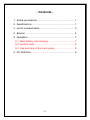
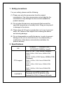
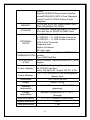
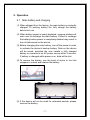
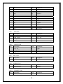
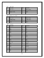
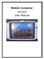
Mobile Computer
WI-300
User Manual
This equipment has been tested and found to comply with the limits
for a Class B Digital Device, pursuant to part 15 of the FCC Rules.
These limits are designed to provide reasonable protection against
harmful interference in a residential installation. This equipment
generates uses and can radiate radio frequency energy and, if not
installed and used in accordance with the instruction, may cause
harmful interference to radio communication. However, there is no
grantee that interference will not occur in a particular installation. If
this equipment dose causes harmful interference to radio or
television reception, which can be determined by turning the
equipment off and on, the user is encouraged to try to correct the
interference by one or more of the following measures:
-- Reorient or relocate the receiving antenna.
-- Increase the separation between the equipment and receiver.
-- Connect the equipment into an outlet on a circuit different from
that to which the receiver is connected.
-- Consult the dealer or an experienced radio/TV technician for
help.
The changes or modifications not expressly approved by the party
responsible for compliance could void the user’s authority to
operate the equipment.
To comply with the FCC RF exposure compliance requirements,
this device and its antenna must not be co-located or operating to
conjunction with any other antenna or transmitter.
- Contents 1. Safety precautions........................................................ 1
2. Specifications ............................................................... 1
3. List of included items .................................................... 3
4. Exterior ......................................................................... 4
5. Operation ...................................................................... 7
5.1 Main battery and charging ....................................... 7
5.2 System reset ............................................................ 8
5.3 Use and care of the touch panel .............................. 8
6. Pin Definition ................................................................ 9
-2-
1. Safety precautions
For your safety, please read the following:
(1) Please use only the accessories from the original
manufacturer. Use of any accessories not provided by the
manufacturer may damage the device and invalidate the
product warranty.
(2) Do not place the device in environments that exceed the
specified temperature or humidity limits. Doing so may result
in damage to the device.
(3) Please keep all I/O ports covered when not in use to prevent
water, dirt, metal or other objects from entering the device
and causing damage.
(4) Do not disassemble or modify the device, in order to prevent
damage to the unit or electrical shock. Any disassembly or
modification of the device automatically invalidates the
product warranty.
2. Specifications
OS
Windows 7™, Windows Vista™,
XP/2000/NT4.0/ME/9x, Linux®
Intel® ATOM™ Z5xx Series Processor:
Z500P 0.8GHz, 512K Cache, 400MHz FSB;
(option)
Z510P 1.1GHz, 512K Cache, 400MHz FSB;
(Standard)
CPU support
Z520P 1.33GHz, 512K Cache,533MHzFSB;
(Option)
Z530P 1.6GHz, 512K Cache, 533MHz FSB;
(Option)
Z540P 1.86GHz, 512K Cache,533MHzFSB;
(Option)
CHIPSETS
Intel®US15W System Control Hub
Chrontel® CH7317A SDVO to VGA
Realtek® ALC262 4-Channel HD Audio
Codec
Anpec® APA2822 Stereo Audio Amplifier
Intersil® ISL6261A IMVP-6 Core Regulator
Linear Tech® LTC3850 System Power
Regulator
1 x 200-pin SO-DDR2 DIMM socket, up to
MEMORY
2GB 400/533MHz SO-DDR2
CF Card Slot, routed as parallel ATA slave
STORAGE
SD Card Slot for SD/SD 2.0/MMC Card
2 x USB 2.0 Type-A Connector
2 x RS232C + 1 x USB Combo Connector
2 x RS232C + 1 x USB Cradle Connector
EXTERNAL
VGA D-Sub Connector
PORTS
Earphone Jack
Battery Connector
DC Input Jack
One Mini-PCIe Card Slot for HSDPA 3.5G
COMMUNICATION module
One USIM Card Slot
SYSTEM BIOS
8M-bit AWARD Flash BIOS with ACPI, APM
(FWH)
support
AC: 50 Watts Switching Power Adapter,
UL/CE/PSE Certified
Power (Adapter)
Input: 100-240V AC, Output 12V DC, 5.0A
Power (Battery)
DC: 7.4V / 3600mAH Li-ion Rechargeable
Battery Pack
Dimensions
267 x 203 x 40 mm
Weight
About 1.55 kg
Operating
temperature
Ambient Temperature: 0º C - 40º C
Storage
temperature
Ambient Temperature:10º C - 50º C
Relative humidity
0 % ~ 80 % (without condensation)
Ingress protection
IP54
Drop specification
1.2m
(operating),
(Storage)
-2-
3. List of included items
Upon opening the packaging, please check that the following
items are included:
(1)
(2)
(5)
(1) WI-300 mobile computer
(2) Battery
(3) Charging cable and adaptor
(4) Microsoft ActiveSync installation CD
(5) Quick guide
-3-
(3)
(4)
4. Exterior
4
5
6
7
8
1
9
2
10
3
11
12
13
14
15
16
17
22
18
19
20
21
-4-
1. Multipurpose communications port for:
(1) USB client – use the USB cable included to link the device
to a PC for data synchronization, software installation, etc.
(2) RS-232 – supports standard RS-232 port functions
2. USB host port: the device features two USB host ports, for
use with:
(1) USB memory drive
(2) Keyboard
(3) Mouse
3. VGA port: for standard VGA signal output
4. Built-in microphone
5. Alarm LED: programmable flashing indicator for use with
system or application
6. Wireless connection LED: flashes when Bluetooth connection
is in use
7. Charging status LED operates as follows:
(1) Blue: Operating
(2) Red constant: charging battery. Green: constant: battery
fully charged
(3) Red flash: HDD LED
8. On/Off button
9. Directional arrow keys for moving the cursor
-5-
10. Hot keys: four programmable hot keys
11. Keyboard function key: click this key to open/close the
onscreen keyboard
12. Cradle connector pins: connection between cradle and device
for battery charging and transferring data
13. IrDA data transfer interface
14. CompactFlash slot: supports both CF memory and I/O cards
15. SD slot: supports SD/MMC memory cards
16. Earphone jack: for 3.5mm stereo earphone
17. Stylus
18. Integrated wireless module and backup battery
19. Power adaptor jack
20. Speaker
21. Main battery
22. System reset button
-6-
5. Operation
5.1 Main battery and charging
(1) When shipped from the factory, the main battery is minimally
charged. To prolong battery life, fully charge the battery
before first use.
(2) When battery power is nearly depleted, a popup window will
warn user to recharge the main battery. Failure to recharge
the battery before power is completely deleted may result in
loss of data saved on the device.
(3) Before changing the main battery, turn off the power in order
to activate the device’s backup battery. Data on the device
will be saved, provided the user installs a fully charged
battery or connects to an AC power source within 3 minutes.
If battery is changed while power is on, data will be lost.
(4) To remove the battery, use the back of stylus to turn the
stoppers to unlock and release the battery.
(5) If the device will not be used for extended periods, please
remove the battery.
-7-
5.2 System reset
If an application causes the device to hang, the system can be
reset to operate normally as follows:
Warm reset
Use the stylus to lightly press the reset button on the back of
the device. Warm reset will not delete data saved on the
device.
5.3 Use and care of the touch panel
(1) Do not place any objects on the panel.
(2) Use only the provided stylus on the touch panel. Do not use
your finger or any other pointed objects, to avoid damaging
the panel.
(3) Wipe the touch panel with a smooth, clean, anti-static cloth.
Mild household cleaner or water can also be used if needed.
Do not use alcohol or other industrial strength cleaning
fluids.
(4) Do not pour water directly onto the panel. Cleaning should
be done only with a damp cloth, in order to avoid damaging
the device.
* Specifications are subject to change without prior notice.
** All brand or product names are trademarks or registered
trademarks of their respective companies.
Copyright © 2010 SWIZ Technologies Co., Ltd. All rights
reserved.
-8-
6. Pin Definition
WI-300 MAIN BOARD CONNECTOR PIN DEFINE
JN1
LVDS
PIN
Pin Define
PIN
Pin Define
1
VDD_3.3
11
RxIN2-
2
VDD_3.3
12
RxIN2+
3
GND
13
GND
4
GND
14
RxCLK-
5
RxIN0-
15
RxCLK+
6
RxIN0+
16
GND
7
GND
17
RxIN3-
8
RxIN1-
18
RxIN3+
9
RxIN1+
19
MODE
10
GND
20
SC
JN2
RTC
PIN
Pin Define
PIN
Pin Define
1
RTCBAT
2
GND
JN3
INVERTER CONNECTOR FOR LED PANEL
PIN
Pin Define
PIN
Pin Define
1
GND
4
VCC3 PWM
2
GND
5
VCC
3
VCC INV_ON1
6
VCC
JN4
1.8” HDD
PIN
Pin Define
PIN
Pin Define
1
NC
21
GND
2
NC
22
DMARQ
3
RESET#
23
GND
4
GND
24
DIOW#
5
D7
25
DIOR#
6
D8
26
GND
7
D6
27
IORDY
8
D9
28
GND
-9-
9
D5
29
DMACK#
10
D10
30
INTRQ
11
D4
31
DA1
12
D11
32
PDIAG#
13
D13
33
DA0
14
D12
34
DA2
15
D2
35
CS0#
16
D13
36
CS1#
17
D1
37
DASP#
18
D14
38
3.3V
19
D0
39
3.3V
20
D15
40
DEVADR
JN5
WiFi+BT
PIN
Pin Define
PIN
Pin Define
1
VCC 5V
5
WF_LED
2
USB_DATA-
6
BT_LED
3
USB_DATA+
7
NC
4
GND
8
NC
JN6
Camera CON
PIN
Pin Define
PIN
Pin Define
1
VCC 5V
4
GND
2
USB_DATA-
5
GND
3
USB_DATA+
JN8
MIC CON
PIN
Pin Define
PIN
Pin Define
1
MIC
2
AGND
JN9
AUDIO CON
PIN
Pin Define
PIN
Pin Define
1
AUDIO OUT
2
AGND
JN12
CRADLE CON
PIN
Pin Define
PIN
Pin Define
1
TXD1 (COM3)
13
NC
- 10 -
2
RXD1(COM3)
14
GND
3
RTS1(COM3)
15
GND
4
CTS1(COM3)
16
GND
5
TXD2(COM4)
17
USB_5V
6
RXD2(COM4)
18
NC
7
RTS2(COM4)
19
NC
8
CTS2(COM4)
20
NC
9
NC
21
USB_GND
10
+12V IN
22
USB_DATA-
11
+12V IN
23
USB_DATA+
12
+12V IN
24
USB_GND
JN13
CPLD JTAG
PIN
Pin Define
PIN
Pin Define
1
3.3V
4
TMS
2
TDO
5
TCK
3
TDI
6
GND
JN14
KEY CTRL CON
PIN
Pin Define
PIN
Pin Define
1
KEY_COL0
13
KEY_COL6
2
PWBN_H
14
KEY_COL12
3
KEY_COL1
15
KEY_COL7
4
IDEACT_H
16
IDEACT#
5
KEY_COL2
17
KEY_COL8
6
WLANLED_H
18
-WLAN_LED
7
KEY_COL3
19
PWR_BTN
8
KEY_COL9
20
BAT_POWER
9
KEY_COL4
21
CHARGE_LED
10
KEY_COL10
22
BAT_POWER
11
KEY_COL5
23
ACP_LED
12
KEY_COL11
24
KEY_ROW0
JN16
TOUCH SCREEN
PIN
Pin Define
PIN
Pin Define
1
X+
3
X-
2
Y+
4
Y-
- 11 -
JN17
GPS CON
PIN
Pin Define
PIN
Pin Define
1
VCC 3.3V
5
RTSA(COM1)
2
TXDA(COM1)
6
CTSA(COM1)
3
RXDA(COM1)
7
P1PPS
4
GND
8
NC
JN18
RFID CON (COM2)
PIN
Pin Define
PIN
Pin Define
1
VCC 3.3V
5
RTSB(COM2)
2
TXDB(COM2)
6
CTSB(COM2)
3
RXDB(COM2)
7
NC
4
GND
8
-TRIG
CN1
CF SLOT
PIN
Pin Define
PIN
Pin Define
1
GND
26
CD1#
2
D03
27
D11
3
D04
28
D12
4
D05
29
D13
5
D06
30
D14
6
D07
31
D15
7
CS0#
32
CS1#
8
A10
33
VS1#
9
ATASEL#
34
IORD#
10
A09
35
IOWR#
11
A08
36
WE#
12
A07
37
INTRQ
13
VCC 5V
38
VCC 5V
14
A06
39
CSEL#
15
A05
40
VS2#
16
A04
41
RESET#
17
A03
42
IORDY
18
A02
43
INPACK#
19
A01
44
REG#
20
A00
45
DASP#
- 12 -
21
D00
46
PDIAG#
22
D01
47
D08
23
D02
48
D09
24
IOCS16#
49
D10
25
CD2#
50
GND
CN2
USB
PIN
Pin Define
PIN
Pin Define
1
VCC 5V
3
DATA+
2
DATA1-
4
GND
CN3
USB
PIN
Pin Define
PIN
Pin Define
1
VCC 5V
3
DATA+
2
DATA1-
4
GND
CN5
VGA
PIN
Pin Define
PIN
Pin Define
1
CRT_R
9
NC
2
CRT_G
10
GND
3
CRT_B
11
NC
4
NC
12
CRT_DDCDAT 5V
5
GND
13
CRT_HS
6
GND
14
CRT_VS
7
GND
15
CRT_DDCCLK 5V
8
GND
CN7
STEREO JACK
PIN
Pin Define
PIN
Pin Define
1
AGND
10
LS
2
HP-L
11
RS
3
HP-R
CN8
SIM CON
PIN
Pin Define
PIN
Pin Define
1
VCC
4
GND
2
RST
5
VPP
3
CLK
6
I/O
- 13 -
CN9
SD/MMC
PIN
Pin Define
PIN
Pin Define
1
DAT3
8
DAT1
2
CMD
9
DAT2
3
VSS(GND)
10
CD
4
VDD(3.3V)
11
CW_GND
5
SCLK
12
WP
6
VSS(GND)
13
GND
7
DAT0
14
GND
CN10
SIDE I/O
PIN
Pin Define
PIN
Pin Define
1
TXD3 (COM5)
10
GND
2
RXD3(COM5)
11
GND
3
RTS3(COM5)
12
USB_DATA+
4
CTS3(COM5)
13
USB_DATA-
5
TXD4(COM6)
14
CLIENT_VIN
6
RXD4(COM6)
15
USB_5V
7
RTS4(COM6)
16
USB_DATA-
8
CTS4(COM6)
17
USB_DATA+
9
GND
18
USB_GND
CN11
12V DC-IN
PIN
Pin Define
PIN
Pin Define
1
DC-IN +12V
3
GND
2
GND
4
GND
CN12
BATTERY CONN
PIN
Pin Define
PIN
Pin Define
1
BT+
4
BATTHM
2
SMBCLK
5
BT-GND
3
SMBDATA
CN4
CN6
DDRII CONNECTOR
MINI –PCIE
- 14 -
Specifications are subject to change without prior notice.
** All brand or product names are trademarks or registered
trademarks of their respective companies.
Copyright © 2010 SWIZ Technologies Co., Ltd. All rights
reserved.
- 15 -